

Page 1
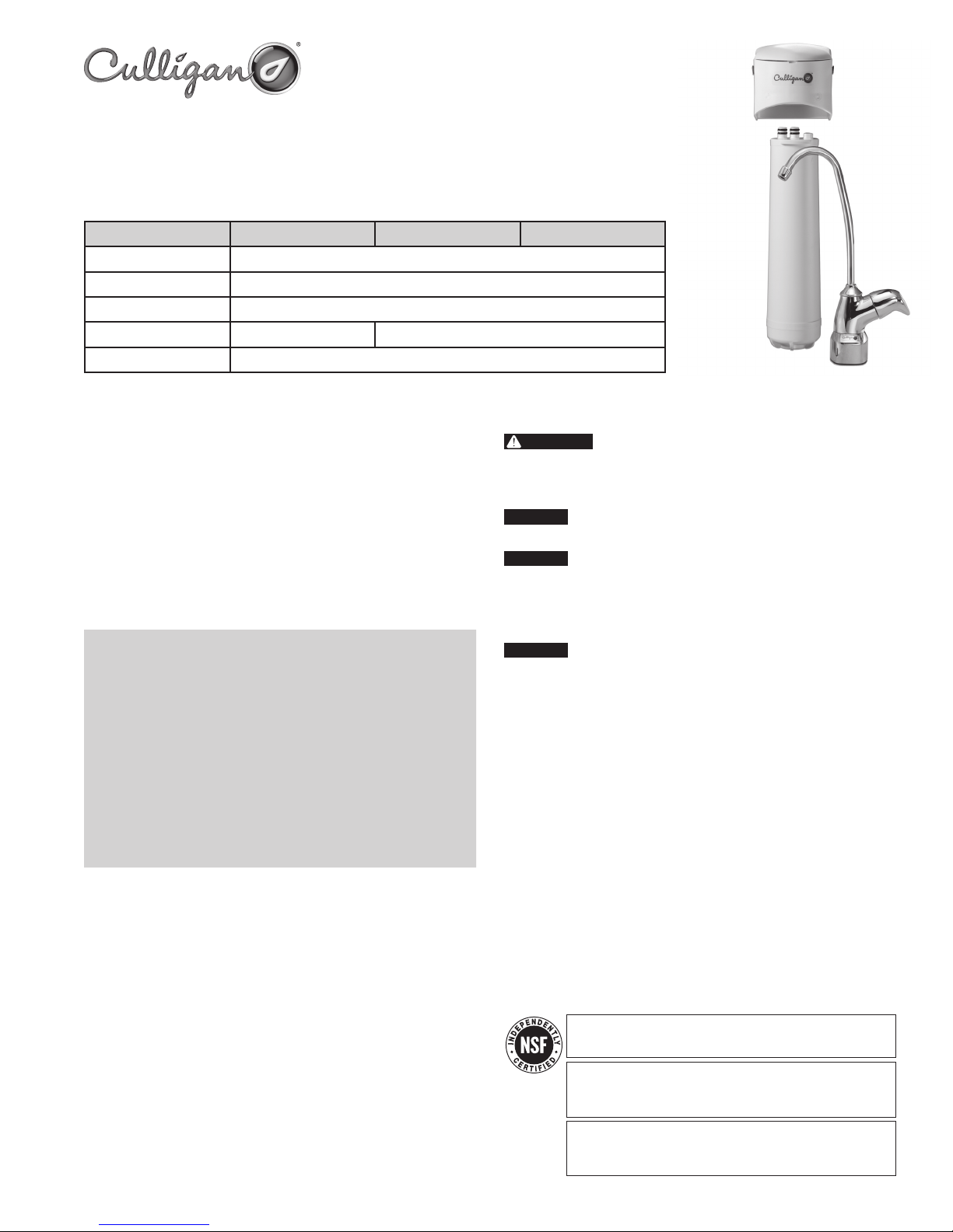
Easy-Change Under-Sink Drinking Water Filter System
Installation and Operating Instructions
Model US-EZ
Specifications
Range / Capacity Level 1 Level 3 Level 4
Pressure Range: 30 – 100 psi (2.1 – 6.9 bar)
Temperature Range: 40–100 ° F (4.4 – 37.7 ° C)
Rated Service Flow: 0.5 gpm (1.9 Lpm)
Filter Capacity: 3000 gallons (11,356 L) 500 gallons (1893 L)
Turbidity: 5 NTU max
Parts Included:
filter head with built-in bracket
•
filter cartridge
•
mounting screws
•
water supply adapter
•
lead-free faucet and fittings
•
1⁄4-inch plastic tubing
•
cartridge change reminder sticker
•
Tools Required
phillips screwdriver• adjustable wrench•
hand or electric drill (cordless recommended)• safety glasses•
utility knife (for plastic tubing)• Teflon® tape•
towel• center punch•
pencil• 1/4-inch & 9/16 or 5/8-inch drill bits•
tape measure• file•
Optional Materials
3" x 3" x 1/2" wood block•
1/8-inch drill bit•
Precautions
WARNING:
unknown quality without adequate disinfection before or after the system. Systems
certified for cyst reduction may be used on disinfected waters that may contain
filterable cysts.
CAUTION:
the filter and water leakage.
CAUTION:
repairs or possible water damage, we strongly recommend that the head of the filter be
replaced every ten years. If the head of your filter has been in use for longer than this
period, it should be replaced immediately. Date the top of any new head to indicate the
next recommended replacement date.
CAUTION:
unattended for an extended period of time.
NOTE:
For cold water use only.
•
Make certain that installation complies with all state and local laws and regulations.
•
The contaminants or other substances removed or reduced by the selected cartridge
•
are not necessarily in your water.
After prolonged periods of non-use (such as during a vacation) it is recommended
•
that the system be flushed thoroughly. Let water run for 10 minutes before using.
The filter cartridges used with this system have a limited service life. Changes in
•
taste, odor, and/or flow of the water being filtered indicate that the cartridge should
be replaced.
Do not use with water that is microbiologically unsafe or of
This filter must be protected from freezing, which can cause cracking of
Because of the product’s limited service life and to prevent costly
Turn off water supply to head without cartridge if it must be left
146153 Rev C 12/06
The US-EZ-1 is tested and certified by NSF International to NSF/ANSI Standard 42 for
the aesthetic reduction of Chlorine Taste and Odor and Nominal Particulate Class III.
The US-EZ-3 is tested and certified by NSF International to NSF/ANSI Standard 42 for
the aesthetic reduction of Chlorine Taste and Odor and Nominal Particulate Class 1.
Standard 53 for the reduction of Cysts, Turbidity, Lead, Lindane and Atrazine.
The US-EZ-4 is tested and certified by NSF International to NSF/ANSI Standard 42 for the
aesthetic reduction of Chlorine Taste and Odor, Chloramines and Nominal Particulate
Class 1. Standard 53 for the reduction of Cysts, Lead, Mercury, VOC, MTBE and Turbidity.
Page 2
Installation
For standard installation on 1/2-inch-14 NPS threads (most common thread on US kitchen faucets)
•
cold water line.
Please read all instructions and precautions before installing and using the US-EZ water filter.
•
Numbered diagrams correspond with numbered steps.
•
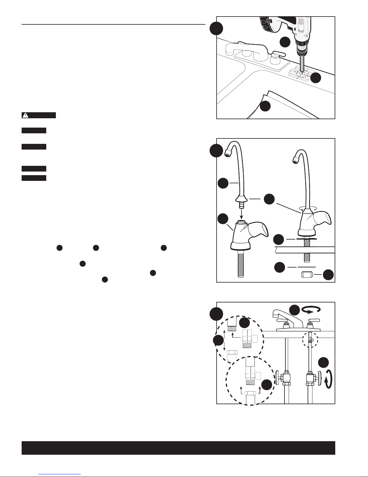
1. Selecting the Faucet Location
NOTE: The drinking water faucet should be positioned with function, convenience and appearance in mind.
An adequate flat area is required to allow faucet base to rest securely. The faucet fits through a 9/16-inch
hole. Most sinks have pre-drilled 13⁄8" or 11⁄2" diameter holes that may be used for faucet installation.
If these pre-drilled holes cannot be used or are in an inconvenient location, it will be necessary to drill a
9/16-inch or 5/8-inch hole in the sink to accommodate the faucet.
WARNING:
come in contact with the eyes. The use of safety glasses and respirator for this procedure is recommended.
CAUTION:
sink, mount the faucet in pre-drilled sprayer hole or drill through counter top next to sink.
CAUTION:
wiring and piping. Make certain that you have ample room to make the proper connections to the bottom
of the faucet.
CAUTION:
CAUTION:
plumber or the counter top manufacturer for advice or assistance.
Line bottom of sink with newspaper to prevent metal shavings, parts or tools from falling
A)
down the drain.
Place masking tape over the area to be drilled to prevent scratches if drill bit slips.
B)
Mark hole with center punch. Use a 1/4-inch drill bit for a pilot hole, then, using a 9/16-inch or
C)
5/8-inch drill bit, drill a hole completely through the sink. Smooth rough edges with a file.
This procedure may generate dusts which can cause severe irritation if inhaled or
DO NOT ATTEMPT TO DRILL THROUGH AN ALL-PORCELAIN SINK. If you have an all-porcelain
When drilling through a counter top make sure the area below the drilled area is free of
Do not drill through a counter top that is more than 1-inch thick.
Do not attempt to drill through a tiled, marble, granite or similar counter top. Consult a
1
C
B
A
2
A
C
B
2. Mounting the Faucet
Insert spout A into faucet body
A)
the faucet body.
Slide black rubber gasket
B)
Accessing the faucet from underneath the sink, slide metal washer E up the faucet stem,
C)
followed by the white plastic stem nut F. Tighten with fingers to secure faucet to sink.
NOTE: do not use pliers to tighten stem nut. Pliers may strip the threads of the faucet stem.
D
Tighten by screwing the spout nut C onto the threads on
B
.
onto threaded faucet stem. Lower faucet stem through hole in sink.
3. Installing the Water Supply Adapter
The supply adapter fits 1/2-inch-14 NPS supply threads.
Turn off cold water supply line.
A)
Turn on the cold water faucet and allow all water to drain from line.
B)
Disconnect cold water line from 1/2-inch-14 NPS threaded stub on bottom of main faucet.
C)
NOTE: If it is too difficult to access the threaded stub on the bottom of the cold water faucet, see
Alternate Installation on page 4.
Apply Teflon® tape onto male threads of faucet stub and supply adapter. Screw the water supply
D)
adapter to the threaded faucet stub as shown.
Using the nut that previously connected the cold water line to the faucet, screw the cold water line
E)
to the male supply adapter threads. Hand tighten nut and snug with wrench.
4. Mounting the Filter System
Select a location under the sink to mount the filter assembly. Choose a location where the filter will
A)
be easily accessible.
NOTE: Allow 11⁄2-inches (38 mm) clearance below housing or 12-inch (305 mm) below filter head
to enable filter cartridge changes.
D
E
F
B
3
D
C
A
E
Technical Support: 1-800-721-9243, Monday-Friday, 8:00 a.m. – 4:30 p.m., CST
2
Page 3
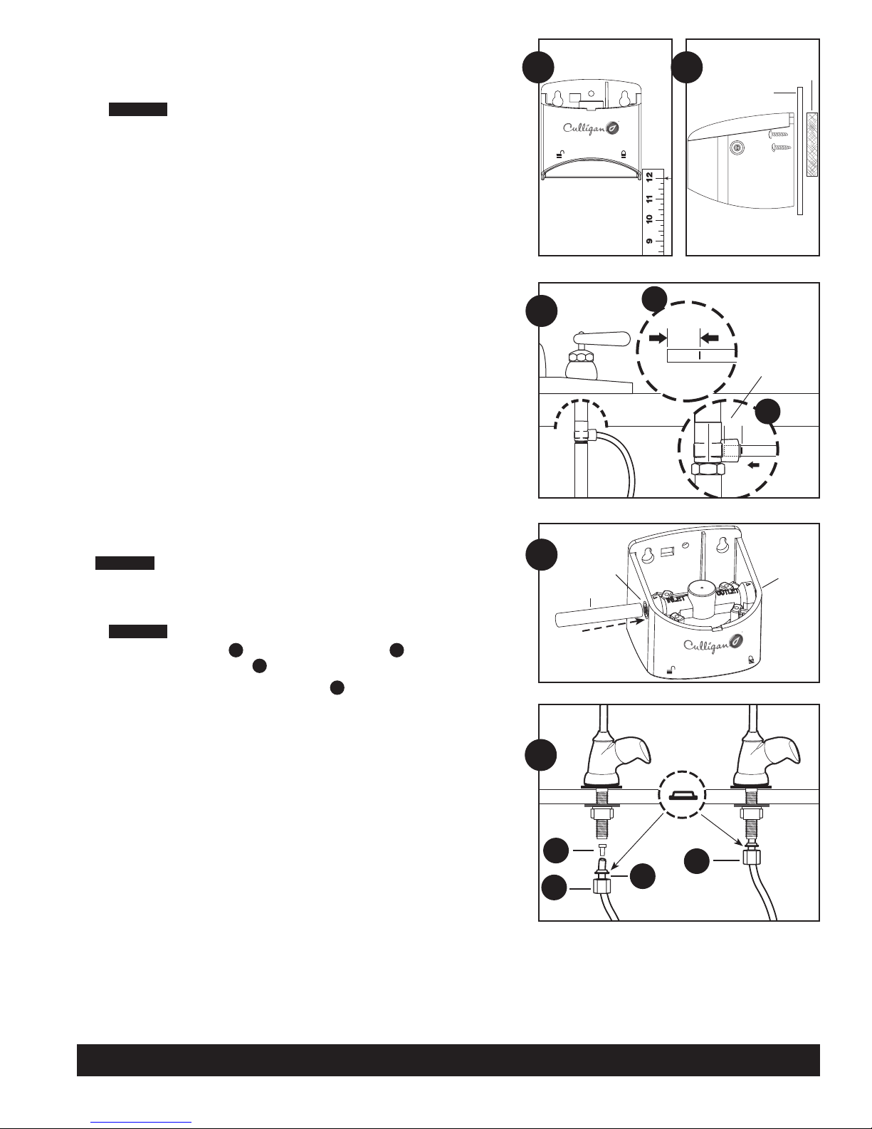
NOTE: Filter head should be mounted in vertical position, use mounting bracket as a template to
mark screw locations. Mount filter head in marked location using screws.
CAUTION:
support the weight of the filter and help prevent strain on the cold water line.
If filter assembly is mounted on a side wall next to drawers, remove drawers. Cabinet wall may
B)
be too thin to support filter assembly. We recommend that a 3" x 3" x 1/2" wood block be used
on the back side of the cabinet to allow the screws to penetrate through the cabinet and into the
wood block. This will allow the filter assembly to be fully supported. Using the filter head assembly
as a template, drill two 1/4-inch holes in the side wall. Position the block of wood behind these
two holes and drill two 1/8-inch holes into the block. Use the two screws provided to mount filter
assembly head to side wall and on the block of wood.
Filter head should be mounted on a stud or firm surface. The mounting bracket will
5. Connecting the Supply Adapter
and Inlet of Filter
Determine the length of plastic tubing needed to connect the inlet (left) side of the filter with the
A)
supply adapter. Be sure to allow enough tubing to prevent kinking and cut the tubing squarely.
Place a mark 5/8-inch (16 mm) from both ends of the tubing.
Wet tubing with water and insert into the supply adapter, 5/8-inch (16 mm) until mark is flush
B)
with fitting.
Wet tubing with water and insert into the filter inlet, 5/8-inch (16 mm) until mark is flush with
C)
fitting.
NOTE: Disconnecting the Tubing from the Quick-Connect Fittings. Routine maintenance and
cartridge replacement will not require that you disconnect the tubing from the filter system;
however, tubing may be quickly and easily removed from the fitting if necessary. First, turn off the
water supply to the filter. Open faucet, then press in the grey collar around the fitting while pulling
the tubing with your other hand.
4A
5
A
4B
5/8"
(16mm)
Cabinet Wall
5/8"
(16mm)
B
Wood
Block
6. Connecting the Faucet
Do not over-tighten compression nut. Use caution not to bend or crimp tubes
CAUTION:
when securing.
Determine the length of plastic tubing needed to connect the outlet (right) side of the filter with
A)
the faucet. Cut the tubing squarely.
CAUTION:
Slide plastic compression nut A over tubing followed by the ferrule B, make sure the ferrule is
B)
oriented properly, then place insert C into the end of tubing.
Push the tubing firmly into the end of the faucet stem D and hand-tighten the compression nut
C)
onto threads until secure. Then tighten approximately 1/2 turn with a wrench.
Do not bend or crimp tube when inserting.
7. Installing the Cartridge
Hold cartridge from the bottom when installing or changing the cartridge. Use caution not to scrape
knuckles on bracket when locking the cartridge into place. Line up the arrow on the cartridge with unlocked
padlock symbol on head. Insert cartridge and turn arrow to locked padlock symbol. See the diagrams in
Filter Cartridge Replacement on page 4.
8. Putting the Filter into Operation
Turn on water supply valve. Check for leaks. If it leaks, see Troubleshooting.
A)
Rotate handle of drinking water faucet counter-clockwise to “on” position. Allow water to run for
B)
10 minutes to flush air and carbon fines (very fine black powder).
Check for leaks before leaving installation. If it leaks, see Troubleshooting.
C)
5C
6
A
Inlet
Insert
ferrule
orientation
C
D
Outlet
B
Technical Support: 1-800-721-9243, Monday-Friday, 8:00 a.m. – 4:30 p.m., CST
3
Page 4

Filter Cartridge Replacement
NOTE: It is recommended that the EZ-1 filter be replaced every year and the EZ-3/EZ-4 every 6 months, or
when you notice a change in taste, odor, or flow of the water being filtered.
Relieve Water Pressure
1)
A) Turn off water supply to the filter and dispense water from drinking water faucet until water flow
stops to relieve pressure.
Remove Old Cartridge
2)
NOTE: Place towel under the system to catch any water drips.
A) Turn arrow from locked to unlocked position.
B) Gently pull down to remove cartridge.
Install New Cartridge
3)
A) Line up arrow with unlocked position on head and insert cartridge.
B) Turn to locked position.
C) Turn on water and check for leaks. If it leaks, see Troubleshooting.
D) Flush water through drinking water faucet for 10 minutes to remove carbon fines. Check for
leaks before leaving installation. If it leaks, see Troubleshooting.
Alternate Installation
This alternate installation will require the purchase of additional fittings to be used with the water supply
adapter. It will be necessary to remove a section of the cold water line to the main faucet. This cold water
line is typically 1/2-inch inner diameter and 5/8-inch outer diameter plastic tubing. Adapter fittings for this
tubing can be either barb type (based on the inner diameter), or compression or quick connect (based on
the outer diameter).
See Illustration A for possible fitting combination. If barb fittings are used, hose clamps must accompany
them. If compression fittings are used, tube inserts should also be used. Always use Teflon® tape on all
male threaded connections.
R2
b
a
R3
a
b
Illustration A
Cold Water Line
Supply Adaptor
(included)
Hose Clamp
Barb Adaptor
Line to inlet of
filter head
Female/Female Adaptor
Barb Adaptor
Hose Clamp
Technical Support: 1-800-721-9243, Monday-Friday, 8:00 a.m. – 4:30 p.m., CST
Cold Water Line
4
Page 5

Replacement Parts
Troubleshooting, continued
US-EZ
1 head assembly
2 RC-EZ-1 filter cartridge Level 1 filtration
3 RC-EZ-3 filter cartridge Level 3 filtration
4 RC-EZ-4 filter cartridge Level 4 filtration
5 lead-free faucet
6 clear 1/4 inch tubing
7 small parts pack
Contact your area retailer or local water treatment professional for replacement cartridge
pricing. For replacement parts, contact your nearest Culligan water filter retailer or call
1-888-777-7962.
1
2 3
4
5
6
7
...on supply adapter connection
Turn off water supply valve and turn on drinking water faucet to release pressure
in system.
Loosen leaking threaded fitting on supply adapter or pull out leaking tubing from fitting.
Inspect to see if plastic tubing is scratched or supply adapter was properly attached. If
tubing is scratched, cut off 1/2-inch to 5/8-inch and reinstall per Step Five: Connecting
the Supply Adapter and Inlet of Filter. Reconnect tubing or tighten compression nut with
fingers, then tighten nut snugly 1/2-turn with wrench. Turn on water supply valve and
check for leaks.
...on faucet/tubing connection
Turn off water supply valve and turn on drinking water faucet to release pressure.
Loosen and remove compression nut fitting on faucet stem. Check if tubing is cut
squarely. Make sure tubing is inserted firmly into end of faucet stem, then retighten
compression nut with fingers until secure, then tighten nut snugly 1/2-turn with wrench.
Turn on water supply valve, then close faucet and check for leaks.
NOTE: If leaks persist, or if there are other leaks on system, turn off water supply. Call
our Technical Support Department at 1-800-721-9243.
Performance Data
Do not use with water that is microbiologically unsafe or of
unknown quality without adequate disinfection before or after the system. Systems
certified for cyst reduction may be used on disinfected waters that may contain
filterable cysts.
NOTE: Substances reduced are not necessarily in your water. Filter must be maintained
according to manufacturer’s instructions, including replacement of filter cartridges.
Troubleshooting
Leaks:
...between head and cartridge
Turn off the water supply to the filter and dispense water from drinking water
1)
faucet until water and airflow stops.
Remove cartridge and inspect o-rings to make sure they are in place and clean.
2)
Install cartridge and turn on water supply. If it still leaks, contact Technical
3)
Support at 1-800-721-9243 M-F 8:00 AM - 4:30 PM CST.
...from fittings
Turn off water supply to the filter and turn on drinking water faucet to release pressure in
system. Press in the grey collar around the fitting while pulling the tubing with the other
hand. Check if tubing is cut squarely or scratched. If tubing is scratched or uneven, cut
off 1/2” to 5/8” and re-install per step five of the installation; connecting the supply
adapter and inlet of filter. Open the water supply valve, then close faucet and check for
leaks. If the leaks persist, or if there are other leaks on the unit, turn off the water supply
then call Technical Support at 1-800-721-9243.
Model US-EZ
Important Notice: Read this performance data and compare the capabilities of this
system with your actual water treatment needs. It is recommended that, before
installing a water treatment system, you have your water supply tested to determine
your actual water treatment needs.
This system has been tested according to NSF/ANSI 42 and 53 for the reduction of the
substances listed below. The concentration of the indicated substances in water entering
the system was reduced to a concentration less than or equal to the permissible limit for
water leaving the system, as specified in NSF/ANSI 42 and 53
RC-EZ-1 Cartridges
This system has been tested according to NSF/ANSI 42 for the reduction of the
substances listed below. The concentration of the indicated substances in water entering
the system was reduced to a concentration less than or equal to the permissible limit for
water leaving the system, as specified in NSF/ANSI 42.
Substance
Standard 42
Chlorine 2.0 mg/L±10%
Particulates
(5µm to<15µm)-Class III
Flow Rate=0.5 gpm (1.89 Lpm) Capacity=3000 gallons (11,356 L) or 12 months
Testing was performed under standard laboratory conditions, actual performance may vary.
Influent Challenge
Concentration
at least 10,000
particles/mL
Maximum
Permissible
Product Water
Concentration
Reduction
Requirements
≥50%
≥85%
Minimum
Reduction
94.8% 97.4%
99.8% 99.9%
Average
Reduction
Technical Support: 1-800-721-9243, Monday-Friday, 8:00 a.m. – 4:30 p.m., CST
5
Page 6

RC-EZ-3 Cartridges
This system has been tested according to NSF/ANSI 42 and 53 for the reduction of the
substances listed below. The concentration of the indicated substances in water entering
the system was reduced to a concentration less than or equal to the permissible limit for
water leaving the system, as specified in NSF/ANSI 42 and 53.
Substance
Standard 42
Chlorine 2.0 mg/L±10%
Particulates
(0.5 to<1µm)-Class I
Standard 53
Cyst Minimum 50,000/L 99.95% 99.95% 99.9%
Turbidity 11 mg/L ± 1 NTU 0.5 NTU 96.4% 98.5%
Lead (pH 6.5) 0.15 mg/L ± 10% 0.010 mg/L 99.3% 99.3%
Lead (pH 8.5) 0.15 mg/L ± 10% 0.010 mg/L 94.8% 98.3%
Atrazine 0.009 mg/L ± 10% 0.003 mg/L 94.1% 94.1%
Lindane 0.002 mg/L ± 10% 0.0002 mg/L 94.5% 98.2%
Flow Rate=0.5 gpm (1.89 Lpm) Capacity=500 gallons (1893 L) or 6 months
Testing was performed under standard laboratory conditions, actual performance may vary
Influent Challenge
Concentration
at least 10,000
particles/mL
Maximum
Permissible
Product Water
Concentration
Reduction
Requirements
≥50%
≥85%
Minimum
Reduction
96.2% 97.4%
99.8% 99.9%
Average
Reduction
RC-EZ-4 Cartridges
This system has been tested according to NSF/ANSI 42 and 53 for the reduction of the
substances listed below. The concentration of the indicated substances in water entering
the system was reduced to a concentration less than or equal to the permissible limit for
water leaving the system, as specified in NSF/ANSI 42 and 53.
Substance
Standard 42
Chlorine 2.0 mg/L ± 10%
Chloramines 3.0 mg/L ± 10% 0.5 mg/L 97.6% 98.0%
Particulates
(0.5 to<1µm)-Class I
Standard 53
MTBE 0.015 ± 20% 0.005 mg/L 69% 96.8% 96.9%
Cyst Minimum 50,000/L 99.95% 99.95% 99.9%
Turbidity 11 mg/L ± 1 NTU 0.5 NTU 96.6% 98.0%
Lead (pH 6.5) 0.15 mg/L ± 10% 0.010 mg/L 99.3% 99.3%
Lead (pH 8.5) 0.15 mg/L ± 10% 0.010 mg/L 94.1% 99.3%
Mercury (pH 6.5) 0.006 mg/L ± 10% 0.002 mg/L 96.7% 96.7%
Mercury (pH 8.5) 0.006 mg/L ± 10% 0.002 mg/L 96.6% 96.6%
Chloroform (VOC surrogate
chemical)
Flow Rate = 0.5 gpm (1.89 Lpm); Capacity = 500 gallons (1893 L) or 6 months
Testing was performed under standard laboratory conditions, actual performance may vary.
Influent Challenge
Concentration
at least 10,000
particles/mL
0.300 mg/L ± 10% 0.015 mg/L 99.8% 99.8%
Maximum
Permissible
Product Water
Concentration
Reduction
Requirements
≥50%
≥85%
Minimum
Reduction
96.2% 97.0%
99.9% 99.9%
Average
Reduction
Test Conditions:
Flow Rate = 0.5 gpm
Inlet Pressure = 60 psi (4.1 bar)
pH = 7.5 ± 1
Temperature = 68° F ± 5° F (20° C ± 2.5° C)
Operating Requirements:
Pressure = 30 - 100 psi (2.1 - 6.9 bar)
Temperature = 40° - 100° F (4.4° -37.7° C)
Turbidity = 5 NTU Max
WARNING: Do not use with water that is microbiologically unsafe or
unknown quality without adequate disinfection before or after the system.
NOTE: Substances reduced are not necessarily in your water. Filter must be
maintained according to manufacturer’s instructions, including replacement of
filter cartridges.
Performance Data - cont.
Organic Chemicals Included by Surrogate Testing:
Applies to US-EZ-4 Only
Substance
alachor 0.050 0.001
atrazine 0.100 0.003
benzene 0.081 0.001
carbofuran 0.190 0.001
carbon tetrachloride 0.078 0.0018
chlorobenzene 0.077 0.001
chloropicrin 0.015 0.0002
2,4-D 0.110 0.0017
dibromochloropropane (DBCP) 0.052 0.00002
o-dichlorobenzene 0.080 0.001
p-dichlorobenzene 0.040 0.001
1,2-dichloroethane 0.088 0.0048
1,1-dichloroethylene 0.083 0.001
cis-1,2-dichloroethylene 0.170 0.0005
trans-1,2-dichloroethylene 0.086 0.001
1,2-dichloropropane 0.080 0.001
cis-1,3-dichloropropylene 0.079 0.001
dinoseb 0.170 0.0002
endrin 0.053 0.00059
ethylbenzene 0.088 0.001
ethylene dibromide (EDB) 0.044 0.00002
haloacetonitriles (HAN):
bromochloroacetonitrile 0.022 0.0005
dibromoacetonitrile 0.024 0.0006
dichloroacetonitrile 0.0096 0.0002
trichloracetonitrile 0.015 0.0003
haloketones (HK):
1,1-dichloro-2-propanone 0.0072 0.0001
1,1,1-trichloro-2-propanone 0.0082 0.0003
heptachlor 0.25 0.00001
heptachlor epoxide 0.0107 0.0002
hexachlorobutadiene 0.044 0.001
hexachlorocyclopentadiene 0.060 0.000002
lindane 0.055 0.00001
methoxychlor 0.050 0.0001
pentachlorophenol 0.096 0.001
simazine 0.120 0.004
styrene 0.150 0.0005
1,1,2,2,-tetrachloroethane 0.081 0.001
tetrachloroethylene 0.081 0.001
toluene 0.078 0.001
2,4,5-TP (silvex) 0.270 0.0016
tribromoacetic acid 0.042 0.001
1,2,4-trichlorobenzene 0.160 0.0005
1,1,1-trichloroethane 0.084 0.0046
1,1,2-trichloroethane 0.150 0.0005
trichloroethylene 0.180 0.0010
trihalomethanes (includes):
chloroform (surrogate chemical)
bromoform 0.300 0.015
bromodichloromethane
chlorodibromomethane
xylenes (total) 0.070 0.001
Influent Challenge
Concentration mg/L
Maximum permissible product water
concentration mg/L
Technical Support: 1-800-721-9243, Monday-Friday, 8:00 a.m. – 4:30 p.m., CST
6
Page 7

Limited Warranty
This limited warranty applies to the Filter Housings only. It does NOT apply to any disposable filter cartridge, which has a life expectancy that varies with the water being filtered. This limited warranty covers
defects in materials and workmanship only for two full years from original date of delivery. Culligan will replace any part which in Culligan’s opinion is defective, unless: (1) any part of the system has been
subjected to any type of tampering, alteration, or improper use after delivery, or (2) any part of the system has been repaired by anyone not approved by Culligan. Our obligation does not include the cost
of shipment of materials. Culligan is not responsible for damage in transit, and claims for such damage should be presented to the carrier by the customer.
This product has been designed solely for use as a housing for a disposable filter cartridge. It is NOT warranted against freezing, and neither this product nor its parts is warranted against defects or
deterioration caused by uses for which this product was not expressly intended.
THE FOREGOING WARRANTY IS EXCLUSIVE AND IN LIEU OF ALL OTHER WARRANTIES, EXPRESSED OR IMPLIED, WHETHER ORAL OR ARISING BY USAGE OF TRADE OR COURSE OF DEALING, INCLUDING,
WITHOUT LIMITATION, ANY WARRANTIES OF FITNESS OR MERCHANTABILITY. THIS WARRANTY IS THE PURCHASER’S SOLE AND EXCLUSIVE REMEDY. IN NO EVENT SHALL CULLIGAN BE LIABLE FOR ANY
ANTICIPATED OR LOST PROFITS, INCIDENTAL DAMAGES, CONSEQUENTIAL CHARGES OR OTHER LOSSES, WHETHER BASED ON BREACH OF CONTRACT, TORTIOUS CONDUCT OR ANY OTHER THEORY, INCURRED
IN CONNECTION WITH THE PURCHASE, INSTALLATION, REPAIR OR OPERATION OF THE OPAQUE FILTER HOUSING. CULLIGAN DOES NOT AUTHORIZE ANYONE TO ASSUME FOR IT ANY LIABILITY OR MAKE ON ITS
BEHALF ANY ADDITIONAL WARRANTIES IN CONNECTION WITH THE OPAQUE FILTER HOUSING OR ANY PART THEREOF.
For servicing under this warranty, return any defective part to YOUR RETAILER within the two-year period referred to above.
IOWA RESIDENTS ONLY:
Store or seller’s name:
Address:
City: State: Zip:
Telephone:
Seller’s signature:
Customer’s signature: Date:
Culligan International Company
One Culligan Parkway • Northbrook, Illinois 60062
www.culligan.com
www.culligan-store.com
© 2006 Culligan International Company, Printed in U.S.A. 146153 Rev C 12/06
Customer Service M-F 8:00 a.m. – 4:30 p.m. CST
Phone: 1-800-721-7360 • Fax: 1-800-721-7390
International: Phone (920) 457-2726 • Fax (920) 457-7366
e-mail: customerservice@culligan.com
Sales & Marketing Correspondence
P.O. Box 1086 • Sheboygan, WI 53082-1086
Fax (920) 457-7366
e-mail: sales-marketing@culligan.com
 Loading...