

Page 1
Specifications
Pressure Range: 30–125 psi (2.1–8.6 bar)
Temperature Range: 40–100°F (4.4–37.8°C)
Parts Included
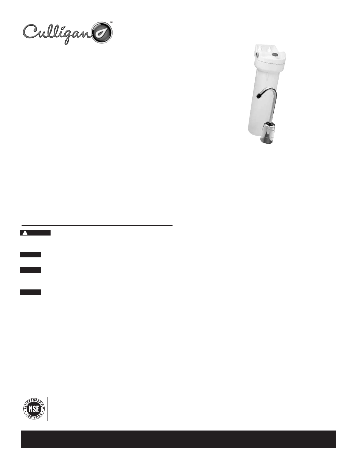
• Filter housing with D-40 filter cartridge, built-in mounting bracket, and quick-connect
fittings
• Lead-free drinking water faucet
• Quick-connect union, tee, and faucet adapter
• 3/8-inch tubing
• Screws for mounting bracket
Optional Materials
• SW-5 housing wrench
Tools Required
• screwdriver • file
• pencil • pipe cutter or hacksaw
Precautions
WARNING: Do not use with water that is microbiologically unsafe or of unknown
quality without adequate disinfection before or after the system. Systems certified for cyst
reduction may be used on disinfected waters that may contain filterable cysts.
CAUTION: Filter must be protected against freezing, which can cause cracking of the filter
and water leakage.
CAUTION: The rubber O-ring provides the water-tight seal between the cap and the bot-
tom of the housing. It is important that the O-ring be properly seated in the groove below
the threads of the housing or a water leak could occur.
CAUTION: Because of the product’s limited service life and to prevent costly repairs or
possible water damage, we strongly recommend that the bottom of all plastic housings be
replaced every ten years. If the bottom of your housing has been in use for longer than this
period, it should be replaced immediately. Date the bottom of any new or replacement
housing to indicate the next recommended replacement date.
The US-640 is Tested and Certified by NSF International against NSF/ANSI
Standard 42 for the aesthetic reduction of Taste and Odor, Chlorine and Particulate
Class I. Standard 53 for the reduction of Lead, Mercury, Lindane, Atrazine, Cyst,
Asbestos, and Turbidity.
Technical Support: 1-800-645-5426
Mon–Fri., 7:30 AM–5 PM CST
11/03 145816 Rev B
Installation and Operating Instructions
Under-Sink Water Filter
Model US-640
NOTE:
• For cold water use only.
• Make certain that installation complies with all state and local laws and
regulations.
• The contaminants or other substances removed or reduced by the selected cartridge are
not necessarily in your water. Ask your local water municipality for a copy of their
water analysis, or have your private well tested by a reputable water testing lab.
• After prolonged periods of non-use (such as during a vacation) it is recommended that
the system be flushed thoroughly. Let water run for 5–6 minutes before using.
• The filter cartridge used with this system has a limited service life. Changes in taste,
odor, color, and/or flow of the water being filtered indicate that the cartridge should
be replaced.
Page 2
2
4
A
B
C
2
D
c
A
3
B
c
A
B
D
C
11⁄
4”
A
1
⁄
4"
1
1
⁄
4"
1
C
B
Pilot Hole
Mounting Hole
Installation
• For standard installation on 3/8-inch cold water line (copper or PVC pipe)
• Please read all instructions and precautions before installing and using your US-640 Undersink Water Filter.
• Numbered diagrams correspond with numbered steps.
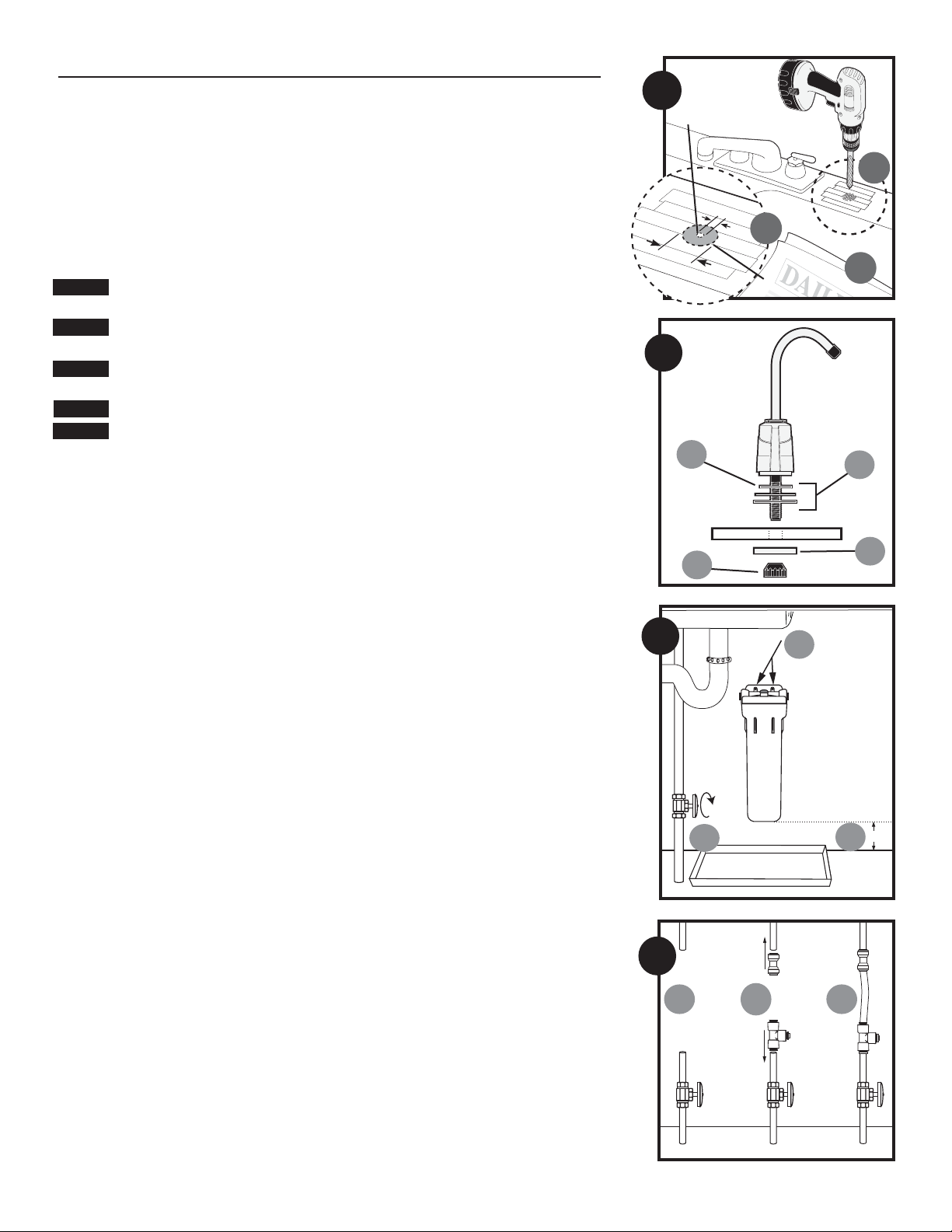
1. Selecting the Faucet Location
NOTE: The drinking water faucet should be positioned with function, convenience, and appearance in mind. An adequate
flat area is required to allow faucet base to rest securely. The faucet fits through a
7
/16-inch hole. Most sinks have pre-
drilled 1
3
/8–inch or 1 1/2–inch diameter holes that may be used for faucet installation. If these pre-drilled holes cannot
be used or are in an inconvenient location, it will be necessary to drill a 1/2-inch hole in the sink for the faucet.
CAUTION: This procedure may generate dusts which can cause severe irritation if inhaled or come in contact with the
eyes. The use of safety glasses and respirator for this procedure is recommended.
CAUTION: DO NOT ATTEMPT TO DRILL THROUGH AN ALL-PORCELAIN OR PORCELAIN-COATED SINK. For applications on
these types of sinks we recommend using the sprayer hole or mounting the faucet through the countertop.
CAUTION: When drilling through a countertop make sure the area below the drilled area is free of wiring and piping.
Make certain that you have ample room to make the proper connections to the bottom of the faucet.
CAUTION: Do not drill through a countertop that is more than 1-inch thick.
CAUTION: Do not attempt to drill through a tiled, marble, granite or similar countertop. Consult a plumber or the coun-
tertop manufacturer for advice or assistance.
The following instructions apply to stainless steel sinks only.
(A) Line bottom of sink with newspaper to prevent shavings, parts or tools from falling down the drain.
(B) Place masking tape over the area to be drilled to prevent scratches if drill bit slips.
(C) Mark point with center punch. Using a
1
/2-inch drill bit, drill a hole completely through the sink. Smooth rough edges
with a file.
2. Mounting the Faucet
(A) Slide small black rubber gasket OR
(B) gasket, aluminum escutcheon plate, and large gasket onto threaded faucet stem. Lower faucet stem through hole in
the sink.
NOTE: Black rubber gasket is designed for smaller holes in sink. Aluminum escutcheon plate with gaskets is designed for
larger, pre-drilled holes.
(C) Slide aluminum channel washer up faucet stem, followed by
(D) black plastic stem nut. Tighten nut with fingers.
NOTE: Do not use pliers to tighten stem-nut. Pliers may strip threads of faucet stem.
3. Mounting the Filter System
(A) Turn off cold water supply and open nearest faucet to release pressure in pipes before starting installation. Place a tray
or towels under the cold water line to catch excess water.
(B) Select location under sink where filter is to be mounted. Use mounting bracket as a template to mark screw locations.
Mount filter in marked location using mounting bracket.
NOTE: (C) Allow 1
1
/2inches (33 mm) clearance below housing to enable filter cartridge changes.
4. Installing Fittings on the Cold Water Line
(A) Using a pipe cutter or hacksaw, remove a 6-inch (152 mm) section of pipe from the 3/8-inch cold water line. Leave a
minimum of 2 inches (51 mm) of pipe above shut-off valve in case pipe must be re-cut at a later time. Deburr ends of
remaining pipe with a file.
(B) Push the quick-connect tee onto the bottom portion of cold water line. Push the quick-connect union onto the top por-
tion of the cold water line.
(C) Measure the distance between the ends of the fittings (approximately 3
1
/2inches [89 mm]) and add 1 1/2inches
(64 mm). Measure and cut a piece of the 3/8-inch plastic tubing to this length. Insert ends of tubing into the quickconnect union and tee on the cold water line as shown. Be sure to push tubing into fitting until it stops (approximately
5
/8-inch).
Page 3
3
5
6
Installation Continued
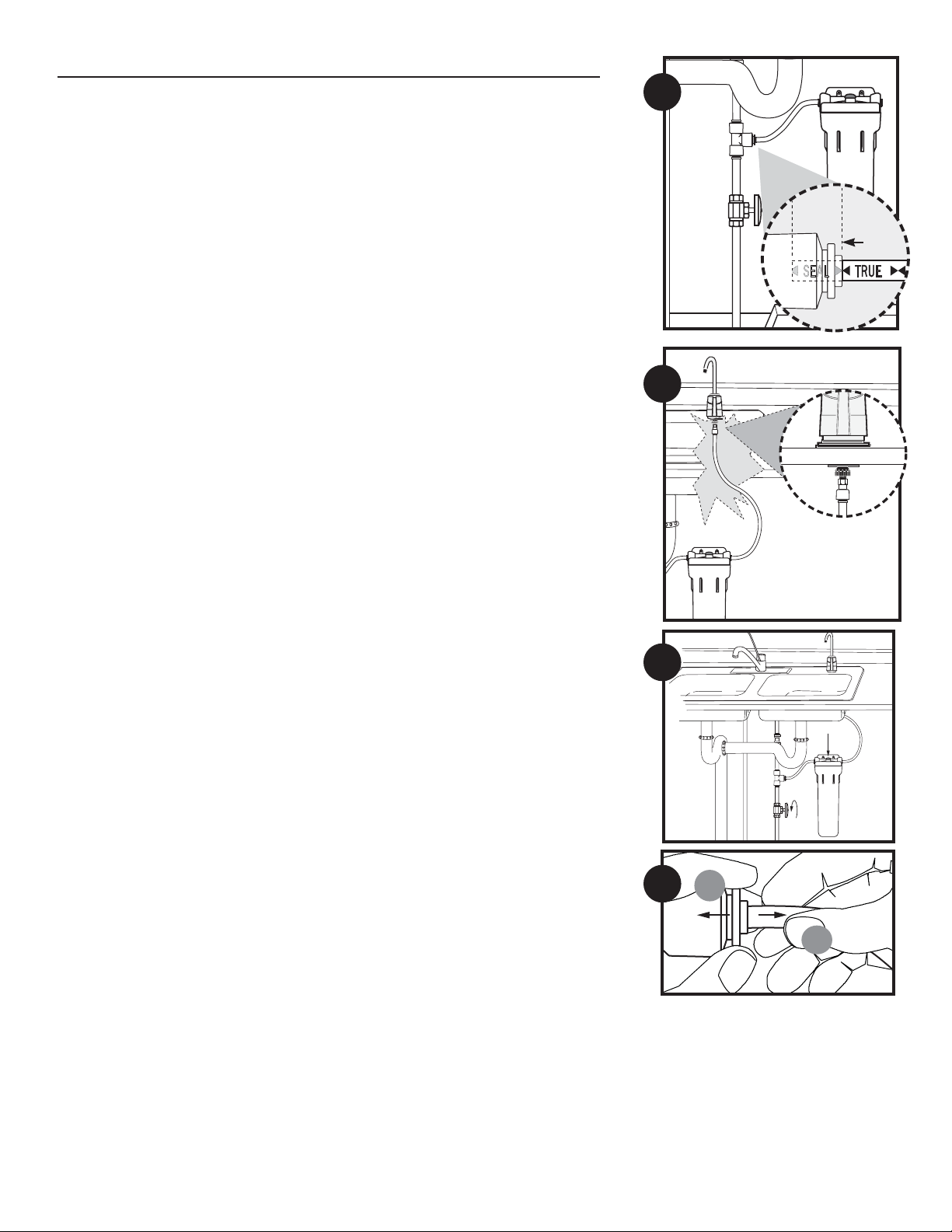
5. Connecting the Tee to the Filter
Determine the length of plastic tubing needed to connect the free port on the tee with the inlet of the filter (inlet and outlet
are marked “IN” and “OUT” on cap). Measure the tubing short enough to prevent kinking. Cut the tubing squarely
between the closest set of black guide arrows. Insert one end of the tubing into the tee and the other end into the inlet fitting. Push tubing into fitting until it stops.
NOTE: When cut between a set of black guide arrows, the tubing should be pushed into the fitting so that the entrance of
the fitting falls between the next set of guide arrows (approximately
5
/8-inch [16 mm]).
6. Connecting the Filter to the Faucet
Thread quick-connect faucet fitting onto faucet stem until hand-tight, then tighten 1/4-turn with a wrench. Determine the
length of plastic tubing needed to connect the outlet of the filter with the quick-connect fitting on the faucet. Measure the
tubing short enough to prevent kinking. Cut the tubing squarely between the closest set of black guide arrows. Insert one
end of the tubing into the outlet fitting and the other end into the faucet fitting. Push tubing into fitting until it stops.
7. Putting the Filter into Operation
Turn on the water supply to allow filter to fill with water, then press the red pressure-relief button on top of the filter to
release trapped air. Check for leaks before leaving installation.
NOTE:
• A drinking water cartridge may contain carbon fines (very fine black powder). After installation and before using the
filtered water, flush the cartridge by running water through it for 5 minutes to remove the fines.
• It is recommended that you run the tap at least 20 seconds prior to using water for drinking or cooking purposes.
8. Disconnecting the Tubing from the Quick-Connect
Fittings
Routine maintenance and cartridge replacement will not require that you disconnect the tubing from the filter cap or other
quick-connect fittings. However, tubing may be quickly and easily removed from the fittings if necessary. First, turn off the
water supply to the filter and open faucet to drain the pipes. Then simply depress the collar
(A) around opening of the fitting while pulling the tubing
(B) with your other hand.
7
8
A
B
Page 4
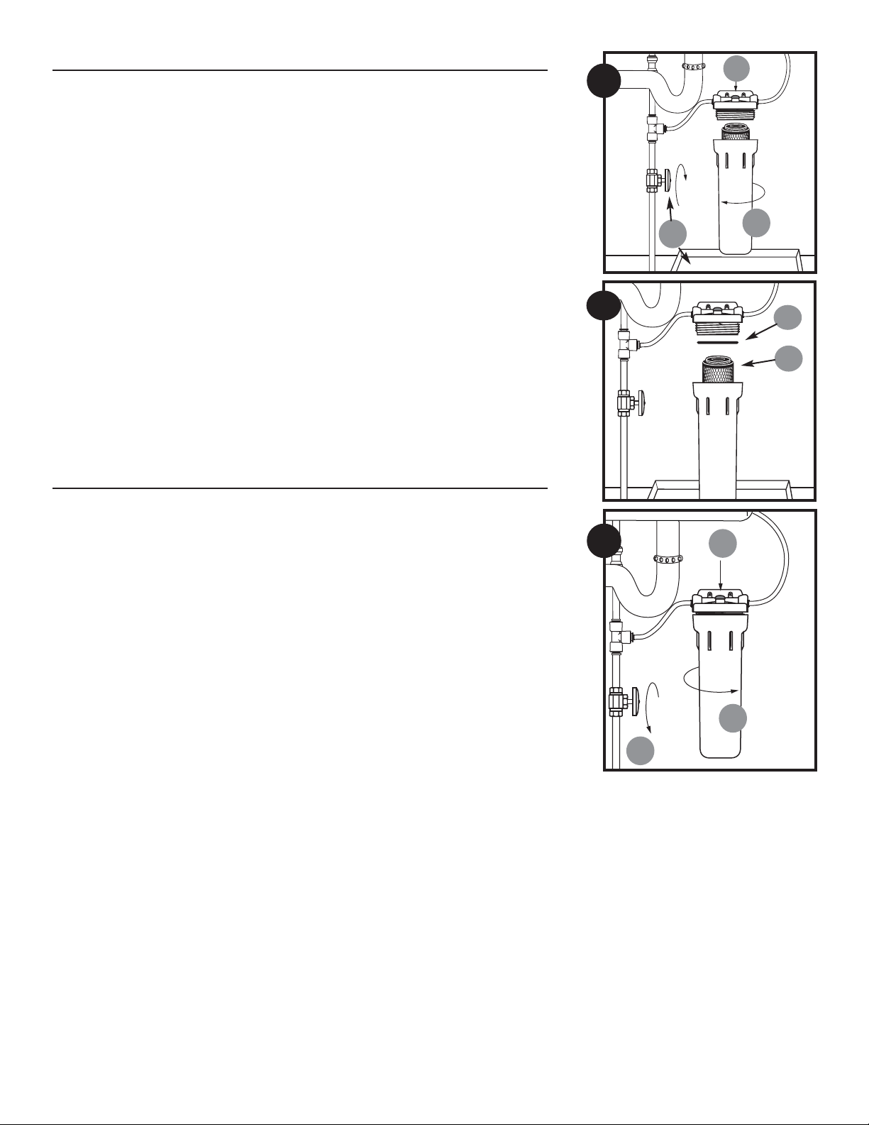
Filter Cartridge Replacement
(A) (1) Turn off water supply to filter and place a tray or towel under the system to catch any water that spills during
removal of the filter cartridge. (2) Depress red pressure-relief button, then (3)unscrew and remove bottom of filter
housing (See Fig. A.)
NOTE: If turning off water supply to filter will also turn off water supply to the rest of the home, be sure to fill a bucket of
water first to allow you to clean housing after it has been removed.
(B) Locate and remove large O-ring (1), wipe clean of lubricant, and set aside. Discard used filter cartridge (2). Rinse out
bottom of filter housing and fill
1
/3full with water. Add 2 tablespoons of bleach and scrub bottom of housing with
nonabrasive sponge or cloth. Rinse throughly. Lubricate O-ring with clean petroleum jelly (Vaseline®). Insert O-ring
in groove and press into place.
NOTE: This step is important to ensure a proper housing seal. Make certain the O-ring is seated level in the groove.
Insert new filter cartridge in bottom of housing. Cartridges with one gasket should be inserted with the gasketed end
toward the threads of the housing (gasketed end would point upwards if housing is mounted as shown in Fig. B).
(C) (1)Screw bottom of housing onto the cap and hand-tighten. DO NOT OVER-TIGHTEN.(2)Slowly turn on the water
supply to allow filter to fill with water, then (3) press the red pressure-relief button on top of filter to release trapped
air. Check for leaks before leaving installation.
NOTE:
• A drinking water cartridge may contain carbon fines (very fine black powder). After installation and before using the
filtered water, flush the cartridge by running water through it for 5 minutes to remove the fines.
• It is recommended that you run the tap at least 20 seconds prior to using water for drinking or cooking purposes.
Troubleshooting
Leaks:
…Between cap and bottom of filter housing
1. Turn off water supply and press the red pressure-relief button. Remove bottom of housing.
2. Clean O-ring and O-ring groove (located directly beneath threads of housing). Lubricate O-ring with silicone grease
and replace securely into groove. Screw bottom of housing onto cap and hand-tighten. DO NOT OVER-TIGHTEN.
…From quick-connect fittings
1. Turn off water supply and turn on faucet to release pressure in pipes. Remove tubing from fitting (see #8 under
Installation) and make sure end of tubing is cut squarely and free of burrs. Reinsert tubing into quick-connect fittings,
making sure to push securely until tubing hits a hard stop.
2. Turn on water supply. If leaks persist, or if there are other leaks on system, turn off water supply. Call Technical
Support at 1-800-645-5426.
A
1
2
B
1
2
3
C
1
3
2
4
Page 5

NOTE: Substances reduced are not necessarily in your water. Filter must be maintained
according to manufacturer’s instructions, including replacement of filter cartridges.
WARNING: Do not use with water that is microbiologically unsafe or of unknown
quality without adequate disinfection before or after the system. Systems certified for cyst
reduction may be used on disinfected waters that may contain filterable cysts.
Contact your area retailer or local water treatment professional for replacement cartridge
pricing.
Suggested Retail Price for Replacement Filter Cartridges: D-40 $39.99
Test Conditions Operating Requirements
Flow Rate = 0.6 gpm Pressure = 30–125 psi (2.1-8.6 bar)
Inlet Pressure= 60 psi (4.1 bar) Temperature= 40–100°F (4.4–37.8°C)
pH = 7.5 ± 1 Turbidity = 5 NTU Max.
Temperature = 68°F±5°F (20°C±2.5°C)
2
1
3
4
11
10
9
5
8
6
7
12
Replacement Parts
1 144802 Pressure-Relief Assembly
2 154530 White Cap
3 143338 Screws for Mounting Bracket
4 151231 O-ring (OR-233)
5 155466 D-40 Filter Cartridge
6 153126 White Housing
7 150424 Housing Wrench (SW-5)
8 151242 Lead-Free Faucet (FT-10)
9 143209 Quick-Connect Tee
10 143410 Quick-Connect Union
11 144805 Quick-Connect Faucet Adapter
12 144097 Clear 3/8-inch Tubing
For replacement parts, contact your nearest retailer or callCulligan Consumer Services at 1-888-777-7962.
Performance Data
Model US-640
Important Notice: Read this performance data and compare the capabilities of this system
with your actual water treatment needs. It is recommended that, before installing a water
treatment system, you have your water supply tested to determine your actual water treatment needs.
This system has been tested according to NSF/ANSI 42 and 53 for reduction of the substances listed below. The concentration of the indicated substances in water entering the
system was reduced to a concentration less than or equal to the permissible limit for water
leaving the system, as specified in NSF/ANSI 42 and 53.
D-40 Cartridge
Substance Influent Challenge Max. Permissible Product Reduction Minimum Average
Concentration Water Concentration Requirements Reduction Reduction
Standard 42 Aesthetic Effects
Chlorine 2.0 mg/L ± 10% ≥ 50% 97%
Particulates at least 10,000 particles/mL ≥ 85% 96%
(0.5 to < 1µm) Class I
Standard 53 Health Effects
Cysts
2)
Minimum 50,000/L 99.95% 99.99% 99.99%
Turbidity 11 ± 1 NTU 0.5 NTU 99.1% 99.4%
Asbestos 107to 108fibers/L >10 99% 99.9% 99.9%
Micrometers in length
Lead 6.5 pH 0.15 mg/L ± 10% 0.010 mg/L 99.3% 99.3%
Lead 8.5 pH 0.15 mg/L ± 10% 0.010 mg/L 94.1% 97.6%
Mercury 6.5 pH 0.006 mg/L ±10% 0.002 mg/L 85% 90.8%
Mercury 8.5 pH 0.006 mg/L ±10% 0.002 mg/L 80.6% 90%
Atrazine 0.009 mg/L ± 10% 0.003 mg/L 89% 89%
Lindane 0.002 mg/L ±10% 0.0002 mg/L 92.4% 92.4%
Flow Rate = 0.6 gpm (2.27 L/min) Capacity = 600 gallons (2271 L) or 6 months
2)
Based on the use of microspheres
Testing was performed under standard laboratory conditions, actual performance may vary.
5
Page 6

Customer Service
M-F 7:30 a.m – 5:00 p.m. CST
Phone: 1-800-634-1455 Fax: 1-888-749-8826
International: Phone (920) 457-9435 • Fax (920) 457-2417
e-mail: customerservice@culligan.com
Sales & Marketing Correspondence
P.O. Box 1086 • Sheboygan, WI 53082-1086
Fax (847) 291-7632
e-mail: sales-marketing@culligan.com
©2003 Culligan International Company, Printed in U.S.A. 11/03 145816 Rev B
Culligan International Company
One Culligan Parkway
Northbrook, Illinois 60062
www.culligan.com
WARRANTY
This warranty applies to the Filter Housing and drinking water faucet only. It does NOT apply to
component parts or any disposable filter cartridge, which has a life expectancy that varies with the
water being filtered. This warranty covers defects in materials and workmanship only for one full
year from original date of delivery. Culligan will replace any part which in Culligan’s opinion is
defective, unless: (1) any part of the system has been subjected to any type of tampering, alteration, or improper use after delivery, or (2) any part of the system has been repaired by anyone
not approved by Culligan. Our obligation does not include the cost of shipment of materials.
Culligan is not responsible for damage in transit, and claims for such damage should be presented
to the carrier by the customer.
This product has been designed solely for use as a housing for a disposable filter cartridge. It is
NOT warranted against freezing, and neither this product nor its parts is warranted against defects
or deterioration caused by uses for which this product was not expressly intended.
THE FOREGOING WARRANTY IS EXCLUSIVE AND IN LIEU OF ALL OTHER WARRANTIES, EXPRESSED
OR IMPLIED, WHETHER ORAL OR ARISING BY USAGE OF TRADE OR COURSE OF DEALING,
INCLUDING, WITHOUT LIMITATION, ANY WARRANTIES OF FITNESS OR MERCHANTABILITY. THIS
WARRANTY IS THE PURCHASER’S SOLE AND EXCLUSIVE REMEDY. IN NO EVENT SHALL CULLIGAN
BE LIABLE FOR ANY ANTICIPATED OR LOST PROFITS, INCIDENTAL DAMAGES, CONSEQUENTIAL
CHARGES OR OTHER LOSSES, WHETHER BASED ON BREACH OF CONTRACT, TORTIOUS CONDUCT
OR ANY OTHER THEORY, INCURRED IN CONNECTION WITH THE PURCHASE, INSTALLATION,
REPAIR OR OPERATION OF THE OPAQUE FILTER HOUSING. CULLIGAN DOES NOT AUTHORIZE ANYONE TO ASSUME FOR IT ANY LIABILITY OR MAKE ON ITS BEHALF ANY ADDITIONAL WARRANTIES
IN CONNECTION WITH THE OPAQUE FILTER HOUSING OR ANY PART THEREOF.
For servicing under this warranty, return any defective part to YOUR RETAILER within the one-year
period referred to above.
Page 7

Especificaciones
Margen de Presión: 30-125 psi/2.1-8.6 bar
Margen de Temperatura: 40-100°F/4.4-37.8°C
Piezas Incluídas
• Portafiltro (carcaza) con un cartucho filtrante D-40, un soporte de montaje incorporado
en la tapa, dos tornillos, y accesorios para una conexión rápida.
• Grifo para el agua de beber libre de plomo.
• Unión para conexión rápida, T, y adaptador para el grifo.
• Tubería de 3/8 pulgada /10 mm
• Tornillos para el soporte de montaje
Materiales Opcionales
SW-5 Llave para el pocillo
Herramienta Necesaria
• Destornillador • Lima
• Lápiz • Cortatubos o sierra para metales
Precauciones
ADVERTENCIA: no use con agua que tiene peligro de microbiología, o la calidad del
agua es desconocida sin desinfectarla adecuadamente antes o después del sistema filtrante.
Sistemas certificados para la reducción de quistes, se pueden usar en aguas desinfectadas
que pueden contener quistes filtrables.
PRECAUCIÓN: este portafiltro (carcaza) tiene que protegerse contra congelación. Fracaso
de hacerlo puede resultar en grietas en el pocillo causando goteras.
PRECAUCIÓN: la arandela de caucho provee un sello hermético entre la tapa y el pocillo.
Es mu y importante que la arandela se sienta nivelada en la ranura del pocillo debajo de
las roscas o goteras pueden ocurrir.
PRECAUCIÓN: debido a la duración limitada de este producto y para prevenir reparos
costosos o posibles daños causados por el agua, nosotros recomendamos fuertemente que
todos los pocillos plásticos de todos los portafiltros (carcazas) se reemplazen cada diez
años. Si el pocillo se ha usado por más de este tiempo, se debe reemplazar inmediatamente. Debe marcar la fecha de compra del pocillo nuevo o cuando lo debe reemplazar.
El US-640 es Analizado y Certificado por NSF Internacional contra NSF/ANSI
Norma 42 para la reducción estético de Sabor y Olor, Clorine y Particula Clase I.
Norma 53 para la reducción de Plomo, Mercurio, Lindane, Atrazine, Quistes,
Asbestos, y Turbiedad.
Technical Support: 1-800-645-5426
Mon–Fri., 7:30 AM–5 PM CST
11/03 145816 Rev B
NOTA:
• Para uso con agua fria solamente.
• Asegúrese de que la instalación conforma con todas las reglas y regulaciones locales y estatales.
• Los contaminantes u otras substancias que se quitan o que son reducidas por los cartuchos filtrantes que usted selecciona no se encuentran en su agua necesariamente.
Pregunte por una copia del análisis del agua de su municipalidad de agua local, u
obtenga un análisis de su pozo privado por un laboratorio respetable de analizar agua.
• Después de periodos extendidos sin uso (p. ej. Durante vacaciones) es recomendado
fluir el sistema completamente. Deje fluir el agua por 5-6 minutos antes de usarla.
• El cartucho filtrante usado con este sistema tiene una duración limitada. Cambios en el
sabor, olor, color y/o flujo del agua que está filtrando indica que el cartucho filtrante
se debe reemplazar.
Instrucciones para la Instalación y el Funcionamiento
Filtro de Agua Debajo del Fregadero
Modelo US-640
Page 8

2
4
A
B
C
2
D
c
A
3
B
c
A
B
D
C
11⁄
4”
A
1
⁄
4"
1
1
⁄
4"
1
C
B
Pilot Hole
Mounting Hole
Instalación
• Para una instalación en tuberia cobre o PVC de agua fria de 3/8 de pulgada / 10 mm
• Por favor lea todas las instrucciones para la instalación antes de instalar o usar el filtro para el agua de beber US-640
para instalación debajo del fregadero.
• Los número en el diagrama corresponde con el número del paso.
1. Seleccionando el lugar para el grifo
NOTA:El grifo del agua para beber debe ubicarse teniendo en cuenta la función, conveniencia y aspecto. Se precisa un
lugar plano adecuado para que el grifo se apoye con firmeza. El grifo pasa por un agujero de
7
/16de pulgada. La mayor
parte de los fregaderos ya tienen perforados agujeros de 1 3/8ó 1 1/2de pulgada de diámetro que puede ser utilizado
para instalar un grifo. Si estos agujeros ya perforados no se pueden usar o están ubicados en un lugar poco conveniente,
será necesario taladrar en el fregadero un agujero de 13 mm (
1
/2pulgada) para el grifo.
PRECAUCIÓN: Este procedimiento puede generar polvo que puede causar irritacion severa si se inhala o se pone en con-
tacto con los ojos. El uso de anteojos protectores y respirador son recomendables para este procedimiento.
PRECAUCIÓN: No trate de taladrar porcelana o material es cubiertos de porcelana. En las aplicaciones que ocupen estos
materiales se recomienda usar el agujero del receador, si esta desponible, o taladrar al lado del fregadero.
PRECAUCIÓN: Antes de taladrar para esta instalacion asegure que no haiga alambres electricos o tuberia, debajo del fre-
gadero, que puedan ser dañados con el taladro. Asegure dejar suficiente
espacio para hacer las conexiones necesarias a la llave del agua.
PRECAUCIÓN: No taladre fregaderos de mas de 1 pulgada de espesor.
PRECAUCIÓN: No trate de taladrar a traves de azulejos, granito o materiales similares. Consulte con su plomero o fer-
reteria si necesita mas informacion o asistencia.
Las siguientes instrucciones son aplicables en instalaciones con fregaderos de lamina.
(A) Cubra la base del fregadero con papel para coleccionar los deshechos del maquinado y prevenir que las herramientas
caigan en el tubo del desagüe.
(B) Cubra el espacio que vá a ser taladrado con cinta adhesiva, ésta proteje la superficie y evita resbalar con el taladro.
(C) Marque donde se vá a agujerar con un punzón. Taladre en este punto con una broca de
1
/2pulgada. Suavize los filos
con una lima.
2. Instalando el Grifo
(A) Resbale la arandela negra de caucho O
(B) el escudete de aluminio con la arandela entre el vástago roscado del grifo. Inserte el vástago del grifo en el roto del
fregadero.
NOTA:la arandela negra grande de caucho es diseñada para uso en fregaderos con rotos pequeños. El disco escuchete de
aluminio con la arandela es diseñado para fregaderos que tienen un roto taladrado más grande.
(C) Inserte la arandela canal de aluminio en el vástago del grifo. Siguiente,
(D) inserte la tuerca negra plástica.
NOTA:no use alicates para apretar la tuerca de vástago. Alicates pueden estropear las roscas del vástago del grifo.
3. Instalando el Sistema Filtrante
(A) Cierre el abastecimiento de agua fria y abra el grifo más cercano para dejar escapar el aire entre la tubería, ántes de
empezar la instalación. Ponga un balde debajo de la tubería de agua fria para acumular el exceso de agua, y prevenir
que se derrame.
(B) Seleccione el lugar debajo del fregadero donde desea instalar el sistema filtrante. Instale el sistema filtrante en el
lugar que a marcado con el soporte de montaje.
NOTA: (C)deje un espacio minimo de 1
1
/2pulgada / 38 mm debajo del pocillo para facilitar el cambio del cartucho fil-
trante.
4. Instalando los accesorios en la tubería de agua fria
A. Usando una sierra o un cortatubos, corte 6 pulgadas / 152 mm de la tubería de agua fria de 3/8de pulgada / 10
mm. Asegúrese de mantener 2 pulgadas / 51 mm de tubería encima de la válvula de cierre en caso de que tenga que
volver a cortar la tubería en el futuro. Debe pulir las rebabas en la tubería sobrante con una fila.
B. Empuje la T para conexión rápida entre la parte inferior de la tubería de agua fria. Empuje la unión de conexión rápi-
da entre la parte superior de la tubería de agua fria.
C. Mida la distancia entre las puntas de los accesorios (aproximadamente 3
1
/2pulgadas / 89 mm y añade 1 1/2pulgadas / 38 mm). Mida y corte un pedazo de tubería plástica a esa longitud. Inserte las puntas de la tubería entre la
unión de conexión rápida y la T en la tubería de agua fria como lo demostramos. Asegúrese de empujar la tubería
entre el accesorio hasta cuando pare (aproximadamente
5
/8de pulgada / 16 mm).
Page 9

3
5
6
5. Conectando la T al f iltro
Determine la longitud de la tubería plástica que necesita para conectar el orificio libre de la T con la entrada del filtro (la
tapa del filtro está marcada con "IN" a la entrada, y con "OUT" a la salida). Corte el tubo lo suficientemente corto para
prevenir retorcimientos. Corte el tubo lo más derecho posible entre las flechas negras de guía más cercanas. Inserte el tubo
entre el orificio hasta cuando pare (aproximadamente 5/8de pulgada / 16 mm).
NOTA:cuando corte entre el par de flechas negras de guía, el tubo se debe empujar entre el orificio cosa de que la entrada del orificio caiga entre las dos flechas negras de guía (aproximadamente
5
/8de pulgada / 16 mm).
6. Conectando el filtro al grifo
Manualmente atornille el accesorio de conexión rápida del grifo entre el vástago del grifo hasta que esté asegurado, y
después use una llave y dele
1
/4de vuelta. Determine la longitud de tubería plástica necesaria para conectar la salida del
filtro con el accesorio de conexión rápida en el grifo. Mida el tubo lo suficientemente corto para prevenir que se
retorcimiento. Corte el tubo lo más derecho posible entre las dos flechas negras de guía más cercanas. Inserte una punta
del tubo entre la salida del accesorio y la otra punta entre el accesorio del grifo. Empuje el tubo hasta cuando pare.
7. Como poner el filtro a funcionamiento
abra el abastecimiento de agua para permitir que el filtro se llene de agua, después oprima el botón rojo de aliviar presión
(encima de la tapa) para que escape el aire atrapado. Inspeccione por goteras antes de dejar la instalación.
NOTA:
• Un cartucho filtrante para el agua de beber puede contener pedazos muy finos de carbón (polvo fino negro). Despúes
de instalarlo, debe fluirlo por 5 minutos para quitar estos, antes de usar el agua.
• Usted debe dejar correr el agua por mínimo de 20 segundos antes de usar el agua para beber o cocinar.
8. Desconectando el tubo de los accesorios de conex-
ión rápida
Mantenimiento rutino y reemplazo de los cartuchos filtrantes no require que usted desconecte el tubo de la tapa o los otros
accesorios de conexión rápida; de cualquier modo, el tubo se puede quitar fácilmente de los accesorios si lo es necesario.
Primero, cierre el abastecimiento de agua al filtro y abra el grifo para desaguar la tubería. Después, simplemente
(A) oprima el collar al rededor del orificio del accesorio
(B) halando el tubo al mismo tiempo can la otra mano.
7
8
A
B
Page 10

Reemplazo del Cartucho filtrante
(A) (1) Cierre el abastecimiento de agua fria al filtro y ponga un balde debajo del sistema para acumular el agua que se
derrama cuando cambia el cartucho filtrante.
(2) Oprima el botón rojo de aliviar presión, (3) después destornille y quite el pocillo (mire la Fig. A).
NOTA:si cuando usted cierra el abastecimiento de agua al filtro, usted tambien cierra el abastecimiento de agua para el
resto de la casa, asegúrese de tener un balde con agua para que pueda lavar los pocillos después de que los quite.
(B) Localice y quite la arandela redonda grande (1), límpiela del lubricante, y póngala a un lado. Deseche del cartucho
filtrante usado (2). Enjuague el pocillo y llénelo con
1
/3de agua. Agregue 2 cucharadas de descolorante y restriegue
el pocillo con una esponja o un trapo sin abrasivo. Enjuaguelo completamente. Tiene que lubricar la arandela redonda
con grasa de silicone. Localícelo en la ranura y oprimala en su lugar.
NOTA:este paso es muy importante para asegurar un sello apropiado del pocillo. Asegúrese de que la arandela se sienta
nivelada en la ranura.
Inserte el cartucho filtrante nuevo entre el pocillo. Cartuchos filtrantes con una arandella se deben instalar cosa que el
lado con la arandella esté hacia las roscas del portafiltro (el lado con la arandella debe apuntar hacia arriba si el
portafiltro está instaládo como lo demostramos en la Fig. B).
(C) (1)A tornille el pocillo entre la tapa y aprételo manualmente. ASEGÚRESE DE NO SOBREAPRETAR. (2) Lentamente
abra el abastecimiento de agua para permitir que el filtro se llene con agua, (3) después oprima el botón rojo de presión encima de la tapa del filtro para permitir que se escape todo el aire atrapado. Inspeccione por goteras antes de
dejar la instalación.
NOTA:
• Un cartucho filtrante para el agua de beber puede contener pedazos muy finos de carbón (polvo fino negro). Después
de instalarlo, debe fluirlo por 5 minutos para quitar estos, antes de usar el agua.
• Usted debe dejar correr el agua por mínimo de 20 segundos antes de usar el agua para beber o cocinar.
Reparaciones
Goteras:
…Entre la tapa y el pocillo
1. Cierre el abastecimiento de agua y oprima el botón rojo de aliviar presión. Quite el pocillo.
2. Límpie la arandela redonda y la ranura (localizada directamente debajo de las roscas del pocillo). Lubrique la aran-
dela redonda con grasa de silicone y póngala de nuevo aseguradamente entre la ranura. Atornille el pocillo entre la
tapa y aprételo manualmente. NO SOBREAPRIETE.
…En los accesorios de conexión rápida
1. Cierre el abastecimiento de agua y abra el grifo para dejar escapar la presión en la tubería. Quite la tubería del accesorio (mire #3
bajo Instalación) y asegúrese de cortar la punta del tubo lo más derecho posible y de pulir las rebabas. Vuelva a insertar el tubo
entre los accesorios para conexión rápida, asegurandose de empujar aseguradamente hasta que llegue a un pare seco.
2. Abra el abastecimiento de agua. Si las goteras persisten, o si tiene otras goteras en el sistema, cierre el abastecimiento de agua. Llame gratis al Departamento de Ayuda Técnica 1-800-645-5426.
A
1
2
B
1
2
3
C
1
3
2
4
Page 11

Piezas de Repuesto
1. 144802 Ensamblaje del botón de presión
2. 154530 Tapa blanca
3. 143338 Tornillos para el soporte de montaje
4. 151231 Arandela modelo OR-233
5. 155466 Cartucho filtrante D-40
6. 153126 Pocillo blanco / US-640
7. 150424 Llave para el pocillo, modelo SW-5
8. 151242 Grifo libre de plomo, modelo FT-10
9. 143209 Conexión rápida estilo T
10. 143410 Unión para una conexión rápida
11. 143411 Adaptador para una conexión rápida al grifo
12. 144097 Tubería de 3/8 de pulgad / 10 mm
Por piezas de reemplazo, póngase en contacto con el minorista más cercano o llame gratis al departamento de servicios Culligan 1-888-777-7962.
2
1
4
5
6
NOTA:substancias reducidas no se encuentran en su agua necesariamente. El sistema y el
cartucho filtrante se deben mantener de acuerdo con las instrucciones del fabricante.
ADVERTENCIA: no use con agua que tiene peligro de microbiología, o la calidad del
agua es desconocida sin desinfectarla adecuadamente antes o después del sistema filtrante.
Sistemas certificados para la reducción de quistes, se pueden usar en aguas desinfectadas
que pueden contener quistes filtrables.
Contacte al minorista más cercano o un profesional para el tratamiento de agua por el precio de los cartuchos filtrantes.
Precio sugerido para vender cartuchos filtrantes al por menor: D-40 $39.99
Condiciones de Prueba Requisitos para el Funcionamiento
Régimen de Flujo = 0.6 gpm Presión = 30–125 psi/ 2.1-8.6 bar
Presión de Entrada= 60 psi/ 4.1 bar Temperatura= 40–100°F/4.4-37.8°C
PH = 7.5 ± 1 Turbiedad = Máximo 5 NTU
Temperatura = 68°F±5°F/20°C±2.5°C
3
11
10
9
8
7
12
Datos de Funcionamiento
Modelo US-640
Aviso Importante:lea estos datos de funcionamiento y compare la capacidad de este sistema con las necesidades de su agua. Se recomienda que, antes de instalar un sistema
para tratar el agua, usted debe obtener un análises de su abastecimiento de agua para
determinar cuales son las necesidades reales de su agua.
Este sistema ha sido probado de acuerdo a las normas NSF/ANSI 42 y 53 para la reducción de
las substancias indicadas a continuación. La concentración de las substancias indicadas en el
agua entrante al sistema se redujo a una concentración inferior o igual al límite permitido para
el agua que sale del sistema, según se especifica en las normas NSF/ANSI 42 y 53.
Cartucho filtrante D-40
Substancia Concentración desafiante Concentración máxima del Requisitos Mínimo Promedio
del afluente producto permitida en el agua de reducción de reducción de reducción
Norma 42 Efectos Esteticos
Cloro 2.0 mg/L ± 10% ≥ 50% 97%
Particulas por lo menos 10,000 particulas/mL ≥ 85% 96%
(0.5 a < 1µm) Clase I
Norma 53 Health Effects
Quistes
2)
Mínimo 50,000/L 99.95% 99.99% 99.99%
Turbididad 11 ±1 NTU 0.5 NTU 99.1% 99.4%
Asbestos 107a 108fibras/L >10 99% 99.9% 99.9%
Longitud en micras
Plomo 6.5 pH 0.15 mg/L ± 10% 0.010 mg/L 99.3% 99.3%
Plomo 8.5 pH 0.15 mg/L ± 10% 0.010 mg/L 94.1% 97.6%
Mercurio 6.5 pH 0.006 mg/L ± 10% 0.002 mg/L 85% 90.8%
Mercurio 8.5 pH 0.006 mg/L ± 10% 0.002 mg/L 80.6% 90%
Atrazine 0.009 mg/L ±10% 0.003 mg/L 89% 89%
Lindane 0.002 mg/L ±10% 0.0002 mg/L 92.4% 92.4%
Flujo = 0.6 gpm (2.27 L/min)Capacidad = 600 galones (2271 L) ó 6 meses
2)
Basado en el uso de microesferas
Las pruebas se realizaron bajo condiciones normales de laboratorio; el rendimiento real pudiera variar.
5
Page 12

Customer Service
M-F 7:30 a.m – 5:00 p.m. CST
Phone: 1-800-634-1455 Fax: 1-888-749-8826
International: Phone (920) 457-9435 • Fax (920) 457-2417
e-mail: customerservice@culligan.com
Sales & Marketing Correspondence
P.O. Box 1086 • Sheboygan, WI 53082-1086
Fax (847) 291-7632
e-mail: sales-marketing@culligan.com
©2003 Culligan International Company, Printed in U.S.A. 11/03 145816 Rev B
Culligan International Company
One Culligan Parkway
Northbrook, Illinois 60062
www.culligan.com
GARANTÍA
Esta garantía aplica solamente a los portafiltros filtrantes. NO aplica a ningún cartucho filtrante desechable donde
la duración útil varía con el agua que está filtrando. Esta garantía cubre defectos en los materiales y la fabricación por un año desde la fecha de entrega original. Culligan reemplazará cualquier pieza la cual Culligan considera defectuosa a menos que: (1) cualquier parte del sistema haya sido expuesto a cualquier clase de manipulación, alteración, o uso inapropiado después de entrega, o (2) ha sido reparádo por personal que no es autorizado por Culligan nuestra obligación no incluye el costo de embarque de los materiales. Culligan no es responsable
por daños durante tránsito, y esa clase de reclamos se deben hacer por el cliente directamente al portador.
Este producto ha sido diseñado solamente para uso como un portafiltro para los cartuchos filtrantes desechables.
No está garantizado contra congelación, y ni este producto o sus piezas son garantizadas contra defectos o deteriorización causada por usos los cuales este producto no ha sido expresamente proyectado.
LA GARANTÍA PREVIA ES ESCLUSÍVA Y REEMPLAZA CUALQUIER OTRA GARANTÍA, EXPRESADA O IMPLICITADA,
SEA ORAL O RESULTADO POR USO COMÚN O UN ACUERDO MUTUO, INCLUYENDO, SIN LIMITACIÓN,
CUALQUIER GARANTÍA DE FUNCIONAMIENTO O CONDICIONES VENDIBLES. ESTA GARANTÍA ES EXCLUSÍVA Y ES
EL ÚNICO RECURSO LEGAL DEL COMPRADOR, DE NINGUNA MANERA CULLIGAN SERÁ RESPONSABLE POR
NINGUNA PÉRDIDA DE GANANCIAS O GANANCIAS ANTICIPADAS, DAÑOS CONSECUENTES, GASTOS, GASTOS
ACUMULADOS POR EMBARQUE RETRASADO, U OTRAS PÉRDIDAS, SEA SOBRE UN INCUMPLIMIENTO EN EL
CONTRATO, IMCUMPLIMIENTO O ACCIONES SEAN INTENCIONALES, O NEGLIGENTES LAS CUALES CAUSAN
DAÑOS, PERJUICIOS, O CUALQUIER OTRA ESPECULACIÓN, EN RELACIÓN CON ESTA COMPRA, INSTALACIÓN,
REPARACIÓN O FUNCIONAMIENTO DEL PORTAFILTRO OPACO. CULLIGAN NO AUTORIZA A NADIE PARA
RESUMIR POR ELLA CUALQUIER RESPONSABILIDAD O HACER POR ELLA CUALQUIER GARANTÍA ADICIONAL EN
RELACIÓN CON EL PORTAFILTRO OPACO O CUALQUIERA DE SUS PIEZAS.
Para reparaciones cubiertas por esta garantía, devuelva cualquier pieza defectuosa a SU NEGOCIANTE durante el
plazo de un año como le explicamo arriba.
 Loading...