

Page 1
Ultrafiltration System
with SureLock
™
Installation and operating instructions
Model US-3UF
Sistema de ultrafiltración
con SureLock
™
Instrucciones de instalación y uso
Modelo US-3UF
Système d'ultrafiltration
avec SureLock
™
Guide d’installation et d’utilisation
Modèles US-3UF
DRINKING WATER | AGUA POTABLE | EAU POTABLE
Page 2
2 3
PRECAUTIONS
WARNING: Do not use with water that is microbiologically unsafe or of unknown source/quality without
adequate disinfection before or after the system.
CAUTION: Filter housing must be protected against freezing temperatures, frost, snow, sleet, and ice.
Exposure to these elements can produce cracks and product failures.
CAUTION: This product has a limited service life. We recommend that a record be kept regarding the
date of install and any other performed maintenance. Because of the product’s limited service life and
to prevent costly repairs or possible water damage, we strongly recommend that the head of the filter
be replaced every ten years.
CAUTION: Turn off water supply to head and remove cartridges if it must be left unattended for an
extended period of time.
• For cold water use only. Do not use on hot water line.
• After prolonged periods of non-use (such as during a vacation) it is recommended that the system
be flushed thoroughly. Let water run for 5–6 minutes before using.
• The filters recommended for use with this system carry a limited service life. Changes in taste, odor,
color, and/or flow of the water being filtered indicate that the cartridge should be replaced.
• Make certain that installation complies with all state and local laws and regulations.
• The contaminants or other substances removed or reduced are not necessarily in your water.
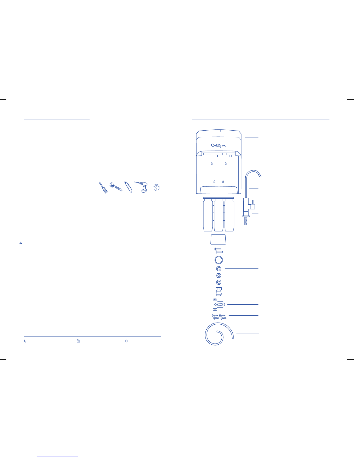
TOOLS & MATERIALS
REQUIRED
• Screwdriver
• Adjustable Wrench
• Utility Knife
• Drill and 1/8˝ Drill Bit
• Plumbers Tape
• Tape Measure
• Safety Glasses
• Masking Tape
• Towels
• Pencil
• Pan or Bucket
PARTS
INCLUDED:
• System
• Battery Cover
• Filter Cassette (US-3UF-R)
• Inlet Cover
• Inlet/Outlet Plugs
• Faucet
• Faucet Base
• Faucet Base Gasket
• Black Washer
• Faucet Stem Nut
• Metal Lock Washer
• Faucet Quick Connect
• Water Supply Adapter
• Mounting Screws
• 3/8˝ Blue Plastic Tubing
• 3/8˝ White Plastic Tubing
SPECIFICATIONS
Pressure Range: 30 –100 psi (207–689 kPa)
Rated Service Flow: 0.75 gpm at 60 psi
(2.8 Lpm at 4.1 bar)
Temperature Range: 40 –100°F (4.4 – 37.7°C)
PARTS INCLUDED:
Battery Cover
System
Filter Cassette (US-3UF-R)
Inlet Cover
Inlet/Outlet Plugs
Faucet
Faucet Base
Faucet Base Gasket
Black Washer
Faucet Stem Nut
Metal Lock Washer
Faucet Quick Connect
Water Supply Adapter
Mounting Screws
3/8˝ White Plastic Tubing
ULTRAFILTRATION SYSTEM
English
18007217360 MON DAYFR IDAY 8:00AM4:30PM CST
3/8˝ Blue Plastic Tubing
Page 3
4 5
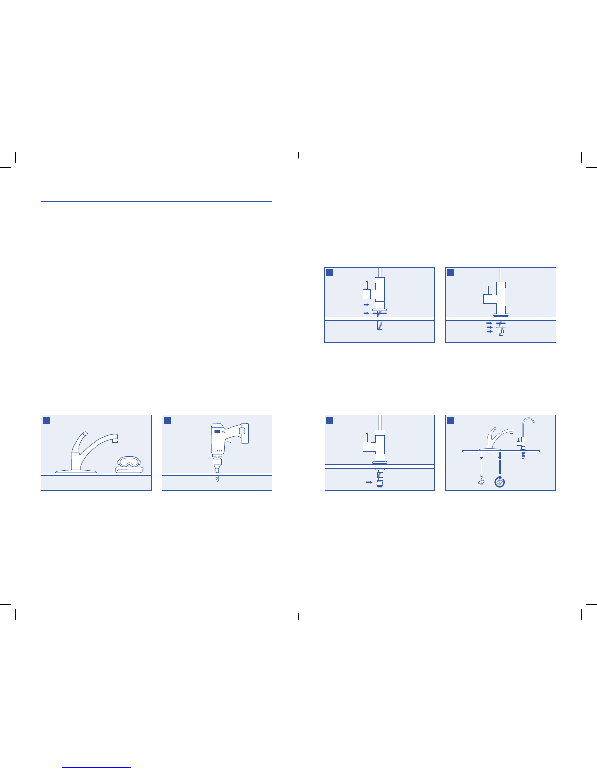
Guide the faucet base gasket onto the faucet
base and then onto the faucet. Lower faucet stem
through hole in sink. Make sure the faucet sits
flat on top of the sink or countertop surface.
From underneath the sink, guide the black
washer onto stem, followed by the metal lock
washer, then screw the faucet stem nut all
the way up the faucet stem and tighten
to secure faucet to sink.
From underneath the sink, hand-tighten the faucet
quick connect fitting onto the faucet stem.
Turn off cold water shut-off valve then turn on
the kitchen faucet and allow all water to drain
from line.
3
5 6
4
INSTALLATION
• Consult your local plumbing codes and install accordingly.
• If your sink does not have a pre-drilled hole, go to step 1, if your sink does have a pre-drilled hole,
go to step 3.
NOTE: The faucet should be positioned with function, convenience and appearance in mind. An adequate
flat area is required to allow faucet base to rest securely. Most sinks have pre-drilled 1-3⁄8˝ or 1-1⁄2˝
diameter holes that may be used for faucet installation. If these pre-drilled holes cannot be used or are
in an inconvenient location, it will be necessary to drill a hole in the sink to accommodate the faucet.
NOTE: DO NOT DRILL THROUGH AN ALL-PORCELAIN OR CAST IRON SINK. If installing on an
all-porcelain or cast iron sink, the faucet must be mounted in a pre-drilled sprayer hole or through
the countertop next to the sink. If the countertop must be drilled, make certain that the area below the
drilling location is free of wiring and pipes. Also, make sure that there is sufficient room to make the
proper connections to the bottom of the faucet mount.
NOTE: Consult with a plumber or the countertop manufacturer for assistance with drilling through
countertops more than 1˝ thick or if it is made of tile, marble, granite, or similar material.
CAUTION: The use of safety glasses and
respirator for this procedure is recommended.
In order to prevent parts and materials from
falling down the drain, line the sink with
newspaper or a towel.
Place masking tape over the area to be drilled
to prevent scratches if drill bit slips.
Using a pencil, mark the drill hole. Drill a hole
for faucet (most sinks have 1-3⁄8˝ or 1-1⁄2˝
diameter holes).
Drill completely through the sink
or countertop.
2
1
Page 4
6 7
NOTE: Routine maintenance and cartridge
replacement will not require that you disconnect
the tubing from the system head; however, tubing
may be quickly and easily removed from the
fitting if necessary. First, turn off the water supply
to the filter. Open kitchen faucet, then press in the
collar around the fitting while pulling the tubing
with your other hand.
You have the ability to attach your tubing to
either side of the system.
Decide which side you wish to use for
your installation.
On the side you will NOT be using, push the
inlet/outlet plugs into the inlet/outlet holes
approximately 5/8" until is stops.
Insert the inlet cover cap by firmly pressing it
into the inlet access hole.
Wet one end of the blue 3/8˝ plastic tubing with
water and push it into the water supply adapter
approximately 5/8˝ until it stops.
Wet the other end of the blue 3/8˝ plastic tubing
with water and push it into the blue system inlet
fitting approximately 5/8˝ until it stops.
NOTE: Do not bend or crimp blue 3/8˝ plastic
tubing when inserting.
11 12
13
COLLAR
Wet one end of the white 3/8˝ plastic tubing with
water and push it into the faucet quick connect
fitting adapter approximately 5/8˝ until it stops.
Wet the other end of the white 3/8˝ plastic tubing
with water and push it into the white system
outlet approximately 5/8˝ until it stops.
NOTE: Do not bend or crimp white 3/8˝ plastic
tubing when inserting.
14
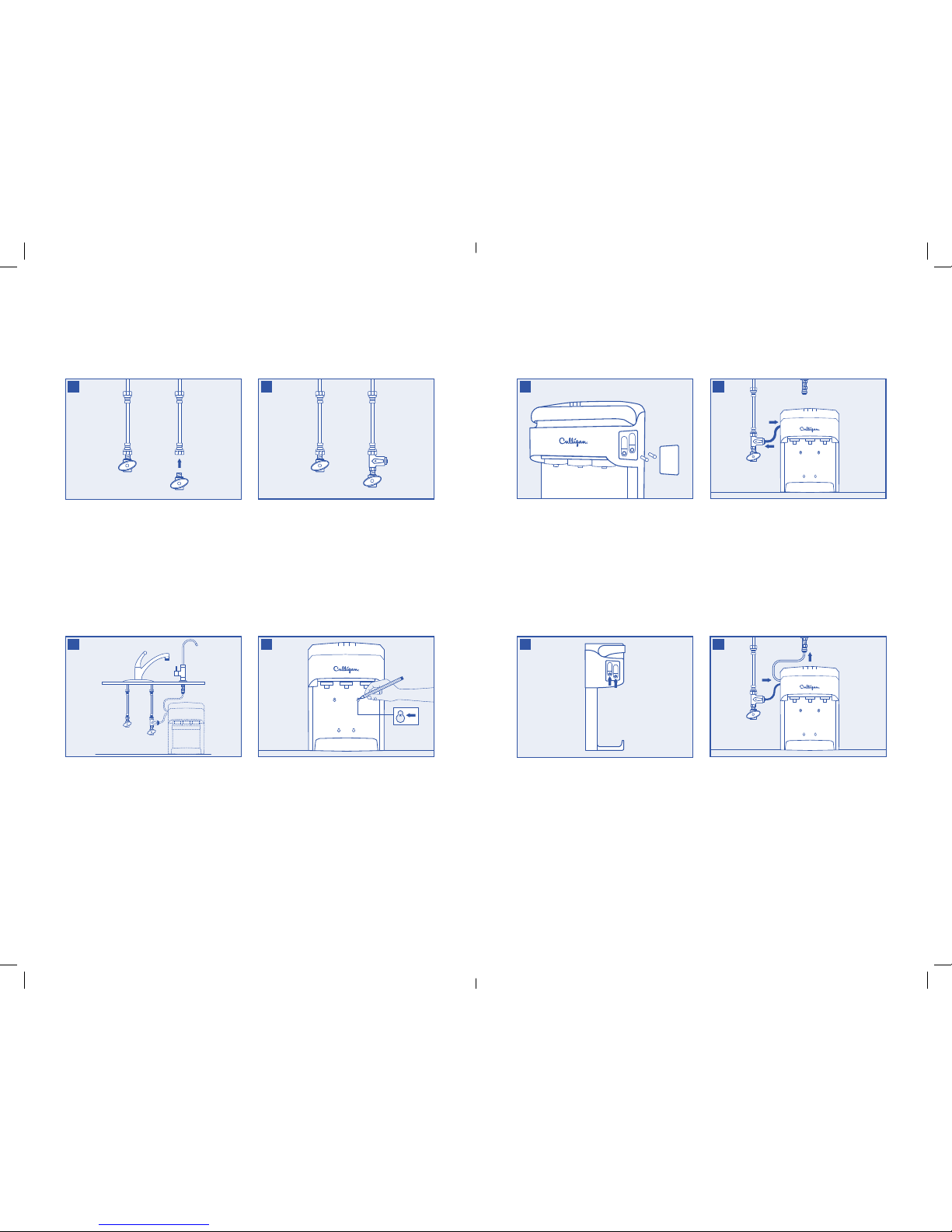
Hand-tighten the water supply adapter to the
cold water shut-off valve as shown.
Hand-tighten the lower end of cold water line
onto the top of the water supply adapter.
8
Choose an easy-to-access area under the sink to
mount the filter system.
SYSTEM MUST BE ON FLOOR FOR LEAK
DETECTOR TO WORK PROPERLY.
NOTE: The filter system must be mounted in a
vertical position.
NOTE: System should be mounted to a stud or
firm surface.
9
Using the built-in bracket on the back of
the system, mark with a pencil the middle
of the holes for the mounting screws on the
wall surface.
Using a 1/8˝ drill bit, drill four pilot holes
for the mounting screws. Insert mounting
screws into the wall with a screwdriver,
leaving approximately 3/8˝ of each mounting
screw exposed.
Hang the system on the eyes of the bracket.
10
Disconnect the cold water line from the
cold water shut-off valve.
NOTE: If rigid plumbing pipe (metal or plastic)
is used, you may need to shorten the pipe using
a hacksaw or pipe cutter to accommodate the
water supply adapter.
7
Page 5

8 9
FILTER CARTRIDGE REPLACEMENT
• Replace your US-3UF-R filter every 6 months for best results.
Guide the base of the cassette into the base of
the system, then rock the top of the cassette
backwards to rest against the system.
Lock the system and cassette into place by
lowering the system handle.
Turn on drinking water faucet and allow water
to run for 10 minutes to flush air and carbon
fines (very fine black powder).
NOTE: Filter life timer will reset when handle
is raised and lowered.
3
Turn off the cold water to the system using the
shut-off valve on the water supply adapter and
dispense water from drinking water faucet until
water flow stops to relieve pressure.
Unlock the system by raising the system handle.
Rock the top of the cassette forwards away from
the system, then gently remove cartridge from
system and discard.
1
2
Turn on the cold water shut-off valve and the
water supply adapter. Check for leaks.
Turn on drinking water faucet and allow water to
run for 10 minutes to flush air and carbon fines
(very fine black powder).
Check for leaks before leaving installation.
If it leaks, see troubleshooting.
Unlock the system by raising the system handle.
Guide the base of the cassette into the base of
the system, then rock the top of the cassette
backwards to rest against the system.
Lock the system and cassette into place by
lowering the system handle.
NOTE: Cassette is designed to go in one way,
make sure cassette label is facing out.
Remove battery cover by gently pulling it
forward and up.
Insert two AA batteries (not provided).
Secure battery cover by sliding it back on
to the system.
15
16
17
Page 6

10 11
ONEYEAR LIMITED WARRANTY
This warranty applies to the Filter Housing. It does NOT apply to any disposable filter cartridge where
life expectancy varies with the water being filtered. This warranty covers defects in material and
workmanship only for 1 full year from the original date of delivery. Culligan will replace any part which
in Culligan’s opinion is defective, unless: (1) any part of the unit has been subjected to any type of
tampering, alteration, or improper use after delivery, or (2) it has been repaired by anyone not approved
by Culligan. Culligan is not responsible for damage in transit, and claims for such damage should be
presented to the carrier by the customer. This warranty does not cover any labor, transportation, or
shipping expenses incurred. The hiring of any individual or service to install or maintain this product is
done at the discretion and expense of the purchaser.
This product has been designed solely for use as a housing for a disposable filter cartridge. It is
NOT warranted against freezing or surges in water pressure, and neither this product nor its parts
is warranted against defects or deterioration caused by uses for which this product was not
expressly intended.
THE FOREGOING WARRANTY IS EXCLUSIVE AND IN LIEU OF ALL OTHER WARRANTIES, EXPRESSED
OR IMPLIED, WHETHER ORAL OR ARISING BY USAGE OF TRADE OR COURSE OF DEALING, INCLUDING,
WITHOUT LIMITATION, ANY WARRANTIES OF FITNESS OR MERCHANTABILITY. THIS WARRANTY IS THE
PURCHASER’S SOLE AND EXCLUSIVE REMEDY, IN NO EVENT SHALL CULLIGAN BE LIABLE FOR ANY
ANTICIPATED OR LOST PROFITS, INCIDENTAL DAMAGES, CONSEQUENTIAL DAMAGES, COSTS, TIME
CHARGES OR OTHER LOSSES, WHETHER BASED ON BREACH OF CONTRACT, TORTIOUS CONDUCT OR
ANY OTHER THEORY, INCURRED IN CONNECTION WITH THE PURCHASE, INSTALLATION, REPAIR OR
OPERATION OF THIS PRODUCT. CULLIGAN DOES NOT AUTHORIZE ANYONE TO ASSUME FOR IT ANY
LIABILITY OR TO MAKE ON ITS BEHALF ANY ADDITIONAL WARRANTIES IN CONNECTION WITH THE
FILTER HOUSING OR ANY PART THEREOF.
For servicing under this warranty, return any defective part to YOUR RETAILER within the 1 year period
referred to above. Be sure that you complete the online warranty registration within 30 days of purchase
and keep your original receipt, order form, or bill of sale to serve as a proof of purchase before returning.
INDICATOR GUIDE
• Indicates that the system is on and functioning by periodically flashing.
• Indicates that the batteries need to be replaced.
1. Remove battery cover by gently pulling it forward and up.
2. Replace two AA batteries (not provided).
3. Secure battery cover by sliding it back on to the system.
• Indicates that the system has detected a leak.
1. Immediately turn off water supply and refer to “Troubleshooting” section.
• Indicates that the cartridge is at the end of its expected life and should be replaced.
1. Refer to “Filter Cartridge Replacement” section.
TROUBLESHOOTING
LEAKS BETWEEN THE SYSTEM HEAD AND THE FILTER CASSETTE:
1. Turn off the water supply to the filter and dispense water from kitchen faucet until water and
airflow stops.
2. Remove cassette and inspect o-rings to make sure they are in place and clean.
3. Install cassette, turn on water supply and check for leaks.
LEAKS AROUND THE FITTINGS:
1. Turn off the water supply to the filter to relieve pressure.
2. While pulling the 3/8˝ plastic tubing with one hand, press in on the collar around the inlet and/or
outlet fitting. Check to make sure that the 3/8˝ plastic tubing is cut squarely and that it is not
scratched or crimped. If the 3/8˝ plastic tubing is unevenly cut or scratched, cut off 1/2˝ to 5/8˝
and re-install the tubing.
3. Turn on water supply and check for leaks.
LEAKS ON THE WATER SUPPLY ADAPTER CONNECTION:
1. Turn off the water supply to the filter to relieve pressure.
2. Locate the water supply adapter.
• If the 3/8˝ plastic tubing is leaking, follow the previous steps (“Leaks around the fittings”).
• If the thread between the water supply adapter and the cold water line is leaking,
tighten more securely.
3. Turn on water supply and check for leaks.
If leaks persist, or if there are other leaks on system, turn off water supply. Call technical support
at 1-800-721-7360.
PRODUCT REGISTRATION
Please be sure to go online within 30 days of purchase and register your product at
www.register.culligan.com.
Page 7

12 13
PRECAUCIONES
ADVERTENCIA: No utilice este producto con agua que no sea microbiológicamente segura, o cuya
fuente o nivel de calidad se desconozca, sin desinfectar primero el sistema de forma adecuada, antes
o después de la instalación.
PRECAUCIÓN: Se debe proteger la cubierta del filtro de las temperaturas muy bajas, la escarcha, la
nieve, el aguanieve y el hielo. Si se expone a estas condiciones, se pueden producir grietas y fallas en
el producto.
PRECAUCIÓN: Este producto tiene una vida útil limitada. Se recomienda mantener un registro de la
fecha de instalación y de todas las tareas de mantenimiento que se lleven a cabo. Debido a la vida útil
limitada del producto y a fin de prevenir reparaciones costosas o posibles daños causados por el agua,
recomendamos enfáticamente que el cabezal del filtro sea cambiado cada diez años.
PRECAUCIÓN: Si tiene que dejar el sistema sin supervisión por un período prolongado, corte el
suministro de agua al cabezal y retire los cartuchos.
• Se debe utilizar únicamente con agua fría. No se debe utilizar en la red de agua caliente.
• Se recomienda enjuagar bien el sistema después de largos períodos en los que no se utiliza
(por ejemplo, durante las vacaciones). Deje que el agua corra entre 5 y 6 minutos antes de
de utilizarlo.
• Todos los filtros recomendados para utilizar con este sistema tienen una vida útil limitada.
Si se observan cambios en el sabor, el olor, el color o el flujo del agua filtrada, se debe reemplazar
el cartucho.
• Asegúrese de que la instalación se realice de conformidad con todas las leyes y reglamentaciones
estatales y locales.
• Los contaminantes u otras sustancias que el cartucho quita o reduce no necesariamente se
encuentran en el agua.
HERRAMIENTAS Y
MATERIALES NECESARIOS
• Destornillador
• Llave ajustable
• Cuchilla de usos múltiples
• Taladro y broca de 3.2 mm (1/8 in)
• Cinta de teflón
• Cinta métrica
• Gafas de seguridad
• Cinta de enmascarar
• Paños
• Lápiz
• Cubeta o balde
PIEZAS
INCLUIDAS:
• Sistema
• Tapa de la batería
• Casete para filtro (US-3UF-R)
• Tapa de la entrada
• Tapones de entrada o salida
• Grifo
• Base del grifo
• Junta para la base del grifo
• Arandela negra
• Tuerca de vástago para grifo
• Arandela de seguridad de metal
• Grifo de conexión rápida
• Adaptador para suministro de agua
• Tornillos de montaje
• Manguera de plástico azul de 1 cm (3/8 in)
• Manguera de plástico blanca de 1 cm (3/8 in)
ESPECIFICACIONES
Rango de presión: 30 a 100 psi (207 a 689 kPa)
Tasa de flujo de servicio: 0.75 gpm a 60 psi
(2.8 Lpm a 4.1 bar)
Rango de temperatura: 40 a 100°F (4.4 a 37.7°C)
Español
PIEZAS INCLUIDAS:
Tapa de la batería
Sistema
Casete para filtro (US-3UF-R)
Tapa de la entrada
Tapones de entrada o salida
Grifo
Base del grifo
Junta para la base del grifo
Arandela negra
Tuerca de vástago para grifo
Arandela de seguridad de metal
Grifo de conexión rápida
Adaptador para suministro de agua
Tornillos de montaje
Manguera de plástico blanca de 1 cm (3/8 in)
SISTEMA DE ULTRAFILTRACIÓN
Manguera de plástico azul de 1 cm (3/8 in)
18007217360 LUNES A VI ERNES 8:00 A .M. A 4:30 P.M. CST
Page 8

14 15
Guíe la junta para la base del grifo por la base
del grifo y luego por el grifo. Inserte el vástago
del grifo en el orificio del fregadero. Asegúrese
de que el grifo quede completamente asentado
sobre el fregadero o la encimera.
Por debajo del fregadero, guíe la arandela
negra por el vástago, seguida de la arandela
de seguridad de metal; luego, atornille
completamente la tuerca del vástago para grifo
en el vástago del grifo y ajuste para fijar el
grifo al fregadero.
Por debajo del fregadero, ajuste manualmente el
accesorio del grifo de conexión rápida al vástago
del grifo.
Desconecte la válvula de cierre de agua fría, abra
el grifo de la cocina y deje que drene toda el agua
de la línea.
3
5 6
4
INSTALACIÓN
• Consulte los códigos de plomería locales y realice la instalación de conformidad con estas normas.
• Si su fregadero no tiene un orificio para el rociador de agua, consulte el paso 1. Si su fregadero sí tiene
un orificio especial para el grifo, consulte el paso 3.
NOTA: El grifo debe colocarse teniendo en cuenta la funcionalidad, comodidad y apariencia.
Es necesario colocar la base del grifo en una superficie plana para garantizar que quede bien fija.
La mayoría de los fregaderos tiene un orificio previamente perforado de 3.5 cm (1-3/8 in) o 3.8 cm
(1-1/2 in) de diámetro que puede utilizarse para instalar el grifo. Si estos orificios previamente
perforados no pueden usarse o están ubicados inadecuadamente, será necesario perforar un nuevo
orificio en el fregadero para colocar el grifo.
NOTA: NO REALICE PERFORACIONES EN FREGADEROS DE CERÁMICA O HIERRO FUNDIDO
PUROS. Si el grifo debe instalarse en un fregadero de cerámica o hierro fundido puros, debe montarse
en un orificio previamente perforado para el rociador de agua o en la encimera junto al fregadero.
Si debe realizar perforaciones en la encimera, asegúrese de que no haya cables ni tuberías debajo del
lugar donde deben realizarse las perforaciones. También asegúrese de que haya espacio suficiente
para hacer las conexiones adecuadas a la parte inferior del montaje para grifo.
NOTA: Consulte con un plomero o con el fabricante de la encimera para que le brinden asistencia en
relación con perforaciones de encimeras de más de 2.5 cm (1 in) de espesor o de encimeras hechas de
mosaico, mármol, granito u otro material similar.
PRECAUCIÓN: Para llevar a cabo este
procedimiento, se recomienda el uso de gafas
de seguridad y mascarilla antipolvo.
Para evitar que las partes y los materiales se
vayan por el desagüe, cubra el fregadero con un
diario o un paño.
Coloque cinta de enmascarar alrededor del área
donde se debe perforar para evitar rayones si la
broca se resbala.
Con un lápiz, marque el orificio que pretende
perforar. Realice una perforación para el grifo
(la mayoría de los fregaderos tienen orificios de
3.5 cm [1-3/8 in] o 3.8 cm [1-1/2 in] de diámetro).
Realice una perforación que atraviese
completamente el fregadero o la encimera.
2
1
Page 9

16 17
NOTA: Las tareas de mantenimiento de rutina
y el cambio de cartuchos no requieren que se
desconecte la manguera del cabezal del sistema;
sin embargo, la manguera puede extraerse del
accesorio rápida y fácilmente, en caso de que sea
necesario. Primero, corte el suministro de agua
al filtro. Abra el grifo de la cocina y presione el
collar que rodea el accesorio mientras tira de la
manguera con la otra mano.
Es posible conectar la manguera a cualquiera
de los lados del sistema.
Decida qué lado quiere utilizar para la instalación.
Del lado que NO va a utilizar, inserte los tapones
de entrada o salida, aproximadamente, 1.6 cm
(5/8 in) dentro del orificio de entrada o salida,
hasta que haga tope.
Para insertar la tapa de la entrada, presiónela
sobre el acceso del orificio de entrada.
11 12
13
COLLAR
Humedezca un extremo de la manguera de
plástico blanca de 1 cm (3/8 in) con agua e
inserte, aproximadamente, 1.6 cm (5/8 in) de la
manguera en el adaptador para el accesorio del
grifo de conexión rápida, hasta que haga tope.
Humedezca el otro extremo de la manguera
de plástico blanca de 1 cm (3/8 in) con agua e
inserte, aproximadamente, 1.6 cm (5/8 in) de la
manguera en la salida del sistema blanca, hasta
que haga tope.
NOTA: No doble ni pinche la manguera de
plástico blanca de 1 cm (3/8 in) cuando la inserte.
14
Ajuste manualmente el adaptador para
suministro de agua a la válvula de cierre de
agua fría, como se muestra.
Ajuste manualmente el extremo inferior de
la línea de agua fría al extremo superior del
adaptador para suministro de agua.
8
Elija una zona de fácil acceso debajo del
fregadero para montar el sistema de filtro.
EL SISTEMA DEBE COLOCARSE EN EL SUELO
PARA QUE EL DETECTOR DE PÉRDIDAS
FUNCIONE CORRECTAMENTE.
NOTA: El sistema de filtro debe montarse en
posición vertical.
NOTA: El sistema debe fijarse a un montante
o a una superficie firme.
9
Con el soporte incorporado de la parte posterior
del sistema, marque con un lápiz el punto medio
de los orificios para los tornillos de montaje en la
superficie de la pared.
Con una broca de 3.2 mm (1/8 in), perfore
cuatro orificios piloto para los tornillos de
montaje. Inserte los tornillos de montaje en la
pared con un destornillador y deje expuesto,
aproximadamente, 1 cm (3/8 in) de cada tornillo.
Coloque el sistema en las argollas del soporte.
10
Desconecte la línea de agua fría de la
válvula de cierre de agua fría.
NOTA: Si utiliza tubería rígida (de metal o
plástico), es posible que deba acortar la tubería
con una sierra para metales o un cortatubos a fin
de colocar el adaptador para suministro de agua.
7
Humedezca un extremo de la manguera de
plástico azul de 1 cm (3/8 in) con agua e inserte,
aproximadamente, 1.6 cm (5/8 in) de la manguera
en el adaptador para suministro de agua, hasta
que haga tope.
Humedezca el otro extremo de la manguera de
plástico azul de 1 cm (3/8 in) con agua e inserte,
aproximadamente, 1.6 cm (5/8 in) de la manguera
en el accesorio azul de entrada al sistema, hasta
que haga tope.
NOTA: No doble ni pinche la manguera de
plástico azul de 1 cm (3/8 in) cuando la inserte.
Page 10

18 19
REEMPLAZO DEL CARTUCHO DEL FILTRO
• Cambie el filtro US-3UF-R cada 6 meses para obtener mejores resultados.
Inserte la base del casete en la base del sistema;
luego mueva la parte superior del casete hacia
atrás para que quede fijo al sistema.
Para que el sistema y el casete queden
bloqueados en su lugar, baje la palanca
del sistema.
Abra el grifo de agua potable y deje correr el
agua durante 10 minutos para liberar el aire y
eliminar las partículas finas de carbón (un polvo
negro muy ligero).
NOTA: El avisador de vida útil del filtro se
reajustará cuando la manija se eleva y se baja.
3
Desconecte el agua fría del sistema con la válvula
de cierre de agua del adaptador para suministro
de agua y deje correr el agua potable del grifo
hasta que se detenga el flujo para liberar presión.
Para desbloquear el sistema, levante la palanca
del sistema.
Mueva la parte superior del casete hacia adelante
para desprenderlo del sistema, luego retire
suavemente el cartucho del sistema y deséchelo.
1
2
Conecte la válvula de cierre de agua fría y el
adaptador para suministro de agua. Verifique que
no haya pérdidas.
Abra el grifo de agua potable y deje correr el
agua durante 10 minutos para liberar el aire y
eliminar las partículas finas de carbón (un polvo
negro muy ligero).
Verifique que no haya pérdidas antes de dejar el
sistema instalado. Si hay pérdidas, consulte la
sección de resolución de problemas.
Para desbloquear el sistema, levante la palanca
del sistema.
Inserte la base del casete en la base del sistema;
luego mueva la parte superior del casete hacia
atrás para garantizar que quede fijo al sistema.
Para que el sistema y el casete queden
bloqueados en su lugar, baje la palanca
del sistema.
NOTA: El casete es diseñado para ser insertado
en una sola dirección, asegúrese de que la
etiqueta del casete esté mirando hacia afuera.
Para retirar la tapa de la batería, tire de esta
suavemente hacia adelante y luego hacia arriba.
Inserte dos baterías AA (no incluidas).
Para fijar la tapa de la batería, deslícela hacia
atrás sobre el sistema.
15
16
17
Page 11

20 21
GARANTÍA LIMITADA DE UN AÑO
La garantía se aplica a la cubierta del filtro. NO incluye los cartuchos del filtro desechables cuya
expectativa de vida útil depende del tipo de agua que se filtre. La garantía cubre los defectos en el
material y la fabricación solo durante un año completo desde la fecha original de entrega. Culligan
reemplazará cualquier pieza que considere defectuosa, con las siguientes excepciones: (1) si algún
componente de la unidad estuvo sujeto a algún tipo de manipulación, alteración o uso inapropiados
después de la entrega, o bien (2) si se reparó en una agencia que no cuenta con la aprobación de
Culligan. Culligan no asume responsabilidad alguna por los daños durante el transporte, y en caso
de algún reclamo debido a dichos daños, el cliente deberá presentar el reclamo ante el transportista.
Esta garantía no cubre ningún tipo de gastos de envío, transporte o mano de obra en los que se haya
incurrido. La contratación de una persona o un servicio para la instalación o mantenimiento del producto
es responsabilidad del comprador y queda a su exclusivo criterio.
Este producto se diseñó únicamente para que se lo utilice como cubierta de un cartucho del filtro
desechable. NO se ofrece garantía por congelamiento o aumentos de presión del agua; asimismo,
ni el producto ni sus piezas tienen garantía alguna por fallas o deterioros ocasionados por el uso no
previsto de este.
LA GARANTÍA ANTERIORMENTE ESPECIFICADA ES EXCLUSIVA Y SUSTITUYE CUALQUIER OTRA
GARANTÍA, EXPRESA O IMPLÍCITA, YA SEA UNA GARANTÍA VERBAL O UNA QUE DERIVE DEL USO O
LA PRÁCTICA COMERCIAL, INCLUIDA, DE MANERA NO TAXATIVA, CUALQUIER GARANTÍA DE APTITUD
O COMERCIABILIDAD. ESTA GARANTÍA ES EL ÚNICO RECURSO EXCLUSIVO DEL COMPRADOR. BAJO
NINGUNA CIRCUNSTANCIA CULLIGAN ASUMIRÁ RESPONSABILIDAD POR LAS GANANCIAS PREVISTAS
O LAS PÉRDIDAS, LOS DAÑOS CIRCUNSTANCIALES O INDIRECTOS, LOS COSTOS, LOS CARGOS
TEMPORALES U OTRO TIPO DE PÉRDIDAS, INDEPENDIENTEMENTE DE QUE SE RELACIONEN CON EL
INCUMPLIMIENTO DEL CONTRATO, UNA CONDUCTA INADECUADA U OTRA ACCIÓN, EN RELACIÓN
CON LA COMPRA, LA INSTALACIÓN, LA REPARACIÓN O EL FUNCIONAMIENTO DE ESTE PRODUCTO.
CULLIGAN NO AUTORIZA A NINGUNA PERSONA A ASUMIR RESPONSABILIDADES U OTORGAR
GARANTÍAS ADICIONALES EN SU NOMBRE EN RELACIÓN CON LA CUBIERTA DEL FILTRO O CON
ALGUNA DE LAS PIEZAS DE ESTA.
Para obtener un servicio conforme a esta garantía, deberá devolver cualquier pieza defectuosa a SU
COMERCIANTE dentro del plazo de uno año especificado anteriormente. Asegúrese de completar el
registro de garantía en línea dentro de los 30 días a partir de la compra y conserve la factura original,
la orden de compra o el comprobante de venta, ya que sirven como prueba de la compra para poder
realizar una devolución.
GUÍA DE INDICADORES
• Brilla intermitentemente para indicar que el sistema está encendido y en funcionamiento.
• Indica que es necesario cambiar las baterías.
1. Para retirar la tapa de la batería, tire suavemente de esta hacia adelante y luego hacia arriba.
2. Cambie dos baterías AA (no incluidas).
3. Deslice la tapa de la batería hacia atrás para fijarla al sistema.
• Indica que el sistema ha detectado una pérdida.
1. Corte el suministro de agua inmediatamente y consulte la sección “Resolución de problemas.”
• Indica que el cartucho está llegando al fin de su vida útil y debería cambiarse.
1. Consulte la sección “Cambio del cartucho del filtro.”
RESOLUCIÓN DE PROBLEMAS
PÉRDIDAS ENTRE EL CABEZAL DEL SISTEMA Y LOS FILTROS:
1. Corte el suministro de agua al filtro y deje correr el agua del grifo de la cocina hasta que se detengan
los flujos de agua y aire.
2. Extraiga el casete y revise la junta tórica para asegurarse de que esté limpia y en su lugar.
3. Instale el casete, abra el suministro de agua y verifique si hay pérdidas.
PÉRDIDAS ALREDEDOR DE LOS ACCESORIOS:
1. Corte el suministro de agua al filtro para liberar presión.
2. Mientras tira de la manguera de plástico de 1 cm (3/8 in) con una mano, presione el collar que rodea
el accesorio de entrada o salida. Asegúrese de que la manguera de plástico de 1 cm (3/8 in) esté
cortada en ángulo recto y que no esté rasgada ni pinchada. Si la manguera de plástico de 1 cm (3/8 in)
está cortada de forma irregular o está rasgada, corte una parte de entre 1.3 cm (1/2 in) y 1.6 cm
(5/8 in), y vuelva a instalarla.
3. Abra el suministro de agua y verifique si hay pérdidas.
PÉRDIDAS EN LA CONEXIÓN DEL ADAPTADOR PARA SUMINISTRO DE AGUA:
1. Corte el suministro de agua al filtro para liberar presión.
2. Posicione el adaptador para suministro de agua.
• Si hay pérdidas de agua en la manguera de plástico de 1 cm (3/8 in), siga los pasos indicados
anteriormente (en la sección “Pérdidas alrededor de los accesorios”).
• Si hay pérdidas en la rosca entre el adaptador para suministro de agua y la línea de agua fría,
ajuste más la tuerca.
3. Abra el suministro de agua y verifique si hay pérdidas.
Si la pérdida continúa o si hay otra pérdida en el sistema, corte el suministro de agua. Comuníquese con
el servicio de soporte técnico al 1-800-721-7360.
REGISTRO DEL PRODUCTO
Asegúrese de ingresar al sitio web www.register.culligan.com y registrar su producto dentro de los 30
días a partir de la compra.
Page 12

22 23
PRÉCAUTIONS
AVERTISSEMENT : N'utilisez pas ce dispositif avec de l'eau de source ou de qualité inconnue ou qui
présente des dangers microbiologiques sans l'avoir désinfectée avant ou après avoir utilisé le système.
ATTENTION : Le boîtier doit être conservé à l'abri des températures glaciales, du frimas, de la neige,
du grésil et de la glace. L'exposition à ces éléments peut entraîner des fissures et défauts de produit.
ATTENTION : Ce produit a une durée d'utilisation limitée. Nous vous recommandons de noter la date
d'installation et de tout entretien. En raison de la durée d'utilisation limitée du produit et pour prévenir
les réparations coûteuses et les dégâts des eaux, nous recommandons fortement de remplacer la tête
du filtre tous les dix ans.
ATTENTION : Fermez l'alimentation en eau vers la tête et retirez les cartouches en cas de nonutilisation pendant une période prolongée.
• Utilisation prévue exclusivement pour de l'eau froide. Ne pas utiliser sur une conduite d'eau chaude.
• Il est recommandé, après de longues périodes d'inactivité (si vous partez en vacances, par exemple),
de vidanger le système au complet. Laissez l'eau couler 5 à 6 minutes avant de l'utiliser.
• Les filtres recommandés pour utilisation avec le présent système ont une durée d'utilisation limitée.
Toute modification du goût, de l'odeur, de la couleur ou de l'écoulement de l'eau indique que la
cartouche doit être remplacée.
• Assurez-vous que l'installation est conforme aux lois locales et provinciales.
• Les contaminants et les autres substances susceptibles d'être éliminés ou réduits peuvent ne pas
être présents dans votre eau.
OUTILS ET MATÉRIELS
NÉCESSAIRES
• Tournevis
• Clé à molette
• Couteau universel
• Perceuse et mèche de 0,125 po (3,175 mm)
• Bande d'étanchéité de plomberie
• Ruban à mesurer
• Lunettes de sécurité
• Bande adhésive
• Serviettes
• Crayon
• Cuvette ou seau
PIÈCES
COMPRISES:
• Système
• Capot de la batterie
• Cassette pour filtre (US-3UF-R)
• Cache d'entrée
• Bouchons d'entrée/de sortie
• Robinet
• Base du robinet
• Joint à la base du robinet
• Rondelle noire
• Écrou de la tige du robinet
• Rondelle de blocage métallique
• Raccord rapide (Quick Connect) du robinet
• Adaptateur d'alimentation en eau
• Vis de fixation
• Tuyau en plastique bleu de 0,375 po (9,525 mm)
• Tuyau en plastique blanc de 0,375 po
(9,525 mm)
CARACTÉRISTIQUES
Intervalle de pression : 30 à 100 psi (207 à 689 kPa)
Vitesse d'écoulement assignée : 0,75 gpm à 60 psi
(2,8 Lpm à 4,1 bar)
Intervalle de temperature : 40 à 100°F (4,4 à 37,7°C)
Français
PIÈCES COMPRISES :
Capot de la batterie
Système
Cassette pour filtre (US-3UF-R)
Cache d'entrée
Bouchons d'entrée/de sortie
Robinet
Base du robinet
Joint à la base du robinet
Rondelle noire
Écrou de la tige du robinet
Rondelle de blocage métallique
Raccord rapide (Quick Connect) du robinet
Adaptateur d'alimentation en eau
Vis de fixation
Tuyau en plastique blanc de 0,375 po (9,525 mm)
SYSTÈME D'ULTRAFILTRATION
Tuyau en plastique bleu de 0,375 po (9,525 mm)
18007217360 LUNDI AU VENDREDI 8 H À 16 H 30 HNC
Page 13

24 25
Placez le joint de la base du robinet sur la base,
puis placez le robinet lui-même. Faites passer la
tige du robinet dans le trou. Assurez-vous que le
robinet est bien à plat sur le dessus de l'évier ou
du plan de travail.
Depuis le dessous de l'évier, faites glisser sur
la tige la rondelle noire, suivie de la rondelle
de blocage métallique, puis vissez l'écrou de la
tige du robinet jusqu'à atteindre le haut de cette
dernière, puis serrez à la main pour fixer
le robinet sur l'évier.
Depuis le dessous de l'évier, serrez à la main le
dispositif de raccord rapide du robinet sur la tige
de ce dernier.
Fermez la vanne d'arrêt de l'eau froide, puis
ouvrez le robinet de l'évier et laissez toute l'eau
se vider de la conduite.
3
5 6
4
INSTALLATION
• Consultez les codes de plomberie locaux et effectuez l'installation en conséquence.
• Si votre évier n'est pas équipé d'un orifice de vaporisateur, passez à l'étape 1. Si votre évier est doté d'un
orifice dédié pour le robinet, passez à l'étape 3.
REMARQUE : Le robinet doit être positionné de façon correcte, pratique et esthétique. Une surface
plane adaptée est nécessaire pour que la base du robinet repose en toute sécurité. La plupart des éviers
sont dotés de trous pré-percés de 1,375 po (3,5 cm) ou d'1,5 po (3,8 cm) de diamètre qui peuvent être
utilisés pour l'installation du robinet. Si ces trous pré-percés sont inutilisables, ou s'ils se trouvent à un
endroit inaccessible, il faudra percer un trou dans l'évier pour accueillir le robinet.
REMARQUE : NE PAS PERCER DE TROU DANS UN ÉVIER EN PORCELAINE OU EN FONTE.
Si l'installation doit avoir lieu sur un évier en porcelaine ou en fonte, le robinet doit être monté dans
une embase pré-percée ou sur le plan de travail près de l'évier. Si le plan de travail doit être percé,
assurez-vous que la zone située sous le trou est exempte de tout câblage ou tuyau. Assurez-vous que
l'espace est suffisant pour réaliser les raccords sous le robinet.
REMARQUE : Consultez un plombier ou le fabricant du plan de travail pour exécuter les perçages
sur des plans de travail de plus d'1 po (2,54 cm) d'épaisseur, carrelés ou en marbre, granit ou
matériau similaire.
ATTENTION : Pour exécuter cette procédure,
il est conseillé de porter des lunettes de
protection et un masque respiratoire.
Mettez du papier journal ou une serviette au fond
de l'évier pour éviter la chute de matériaux dans
la conduite d’évacuation.
Placez de la bande adhésive autour de la zone
à percer afin d'éviter les rayures en cas de
dérapage du foret.
Marquez l'emplacement du trou à forer avec
un crayon. Percez un trou pour le robinet
(la plupart des éviers sont équipés de
trous de 1,375 po [3,5 cm] ou 1,5 po [3,8 cm]
de diamètre).
Percez l'évier ou le plan de travail de part en part.
2
1
Page 14

26 27
REMARQUE : L'entretien courant et le
remplacement de la cartouche ne requièrent pas
de déconnecter le tuyau de la tête du système;
cependant, le tuyau peut être retiré rapidement et
facilement du raccord si nécessaire. Tout d'abord,
fermez l'alimentation en eau vers le filtre. Ouvrez
le robinet de l'évier, puis appuyez sur le manchon
autour du raccord tout en retirant le tuyau avec
votre autre main.
Vous avez la possibilité de rattacher la tuyauterie
sur les deux côtés du système.
Choisissez le côté que vous souhaitez utiliser
pour votre installation.
Sur le côté que vous n'allez pas utiliser, enfoncez
les bouchons d'entrée/sortie sur 0,625 po dans
les orifices d'entrée/sortie jusqu'à l'arrêt.
Insérez le cache du boîtier d'entrée dans le trou
d'accès d'entrée en appuyant fermement dessus.
Mouillez l'une des extrémités du tuyau en
plastique de 0,325 po et insérez-la dans le
raccord d'alimentation en eau sur environ
0,625 po, jusqu'à l'arrêt.
Mouillez l'autre extrémité du tuyau en plastique
bleu de 0,325 po et enfoncez-la dans le raccord
d'alimentation en eau sur environ 0,625 po,
jusqu'à l'arrêt.
REMARQUE : Ne pliez pas ou ne pincez pas
le tuyau en plastique bleu de 0,325 po lors de
l'insertion.
11 12
13
MANCHON
Mouillez l'une des extrémités du tuyau en
plastique blanc de 0,325 po et insérez-la dans
l'adaptateur du raccord rapide d'alimentation en
eau sur environ 0,625 po, jusqu'à l'arrêt.
Mouillez l'autre extrémité du tuyau en plastique
blanc de 0,325 po et insérez-la dans le raccord
blanc de sortie du système sur environ 0,625 po,
jusqu'à l'arrêt.
REMARQUE : Ne pliez pas ou ne pincez pas
le tuyau en plastique blanc de 0,325 po lors
de l'insertion.
14
Serrez à la main l'adaptateur d'alimentation
d'eau sur la vanne d'arrêt d'eau froide, tel
qu'illustré.
Serrez à la main l'extrémité inférieure de la
conduite d'eau froide sur la partie supérieure
de l'adaptateur d'alimentation d'eau.
8
Choisissez une zone d'accès facile sous l'évier
pour monter le système de filtration.
LE SYSTÈME DOIT ÊTRE AU SOL
POUR QUE LE DÉTECTEUR DE FUITE
FONCTIONNE CORRECTEMENT.
REMARQUE : Le système de filtration doit être
monté en position verticale.
REMARQUE : Le système doit être monté sur un
poteau d'ossature murale ou une surface dure.
9
Marquez avec un crayon les trous pour les vis
de montage sur la surface du mur en utilisant le
support intégré à l'arrière du système.
Avec une mèche de 0,125 po (3,175 mm), percez
quatre trous de guidage pour les vis de fixation.
Insérez les vis de fixation dans le mur à l'aide
d'un tournevis, en veillant à laisser environ
0,375 po (9,525 mm) de chaque vis exposé.
Suspendez le système sur les oeillets du support.
10
Déconnectez la conduite d'eau froide de la
vanne d'arrêt d'eau froide.
REMARQUE : Si vous utilisez une conduite de
plomberie rigide (en métal ou en plastique), vous
devrez peut-être la raccourcir en utilisant une
scie à métaux ou un coupe-tuyau pour pouvoir
installer l'adaptateur d'alimentation en eau.
7
Page 15

28 29
SUBSTITUTION DES CARTOUCHES DE FILTRE
• Remplacez les filtres US-3UF-R tous les 6 mois pour de meilleurs résultats.
Placez la base de la cassette dans la base du
système, puis faites basculer le haut de la
cassette vers l'arrière pour qu'elle repose
contre le système.
Verrouillez le système et la cassette, en
rabaissant la poignée du système.
Ouvrez le robinet d'eau potable et laissez
l'eau couler pendant 10 minutes pour évacuer
complètement l'air et les particules de carbone
(poudre noire très fine).
REMARQUE: La vie du filtre minuterie se
réinitialise lorsque poignée est soulevée
et abaissée.
3
Fermez l'eau froide alimentant le système à l'aide
de la vanne d'arrêt de l'adaptateur d'alimentation
en eau et laissez couler de l'eau à partir du
robinet d'eau potable jusqu'à ce que le débit
s'arrête afin de diminuer la pression.
Déverrouillez le système en soulevant la poignée.
Basculez le haut de la cassette vers l'avant hors
du système, puis retirez doucement la cartouche
et éliminez-la.
1
2
Ouvrez la vanne d'arrêt d'eau froide et
l'adaptateur d'alimentation en eau. Assurez-vous
qu'il n'y a pas de fuites.
Ouvrez le robinet d'eau potable et laissez
l'eau couler pendant 10 minutes pour évacuer
complètement l'air et les particules de carbone
(poudre noire très fine).
Assurez-vous qu'il n'y a pas de fuites avant
de quitter l'installation. En cas de fuite,
reportez-vous à la section Dépannage.
Déverrouillez le système en soulevant la poignée.
Placez la base de la cassette dans la base du
système, puis faites basculer le haut de la
cassette vers l'arrière pour qu'elle repose contre
le système.
Verrouillez le système et la cassette, en
rabaissant la poignée du système.
REMARQUE: La cassette est conçu pour aller
dans un sens, assurez-vous que l'étiquette de
la cassette vers l'extérieur.
Retirez le cache de la batterie en le tirant
doucement vers l'avant et vers le haut.
Insérez deux piles de type AA (non fournies).
Fixez le cache de la batterie en le remettant dans
le système.
15
16
17
Page 16

30 31
GARANTIE LIMITÉE DE 1 AN
La présente garantie s'applique au boîtier du filtre. Elle n'est PAS applicable aux filtres jetables
dont la durée de vie varie selon l'eau qui y est filtrée. Cette garantie couvre les défauts matériels et
de fabrication, pendant la période de 1 an après la date originale de livraison. Culligan s'engage à
remplacer toute pièce qui, à son avis, est défectueuse, sauf : (1) si une partie de l'unité a subi une
altération, modification ou utilisation inadéquate après sa livraison ou (2) elle a été réparée par une
personne non approuvée par Culligan. Culligan rejette toute responsabilité des dommages survenus en
transport, et toute demande relative à de tels dommages doit être présentée par le client à la société de
transport. La présente garantie ne couvre aucuns frais de main-d'œuvre, de transport ou de livraison.
Le recours à un individu ou un service pour l'installation ou l'entretien de ce produit est pris à la
discrétion et aux frais seuls de l'acheteur.
Ce produit est conçu pour une utilisation en tant que boîtier pour un filtre jetable. Il n'est PAS garanti
contre le gel ni les pointes de pression de l'eau. Le produit et ses pièces ne sont pas non plus garantis
contre les défauts et la détérioration causés par une utilisation non explicitement prévue.
LA PRÉCÉDENTE GARANTIE EST EXCLUSIVE, EN LIEU DE TOUTE AUTRE GARANTIE, EXPRIMÉE OU
IMPLICITE, DE MANIÈRE ORALE OU DANS LE CADRE D'UNE VENTE, Y COMPRIS SANS TOUTEFOIS
S'Y LIMITER TOUTE GARANTIE DE CONVENANCE OU DE QUALITÉ MARCHANDE. LA PRÉSENTE
GARANTIE CONSTITUE LE RECOURS SEUL ET EXCLUSIF OFFERT AU CLIENT, CULLIGAN REJETTE
LA RESPONSABILITÉ DE TOUTE PERTE DE PROFITS ANTICIPÉE OU RÉELLE; DE DOMMAGES
ACCESSOIRES ET CONSÉCUTIFS; DE FRAIS MONÉTAIRES, TEMPORELS OU AUTRES; QU'ILS
DÉCOULENT D'UNE RUPTURE DE CONTRAT, DE COMPORTEMENT ILLÉGAL OU DE TOUTE AUTRE
THÉORIE, LIÉS À L'ACHAT, L'INSTALLATION, LA RÉPARATION OU L'UTILISATION DE CE PRODUIT.
CULLIGAN N'AUTORISE PERSONNE À ASSUMER CES RESPONSABILITÉS EN SON NOM OU OFFRIR DES
GARANTIES SUPPLÉMENTAIRES EN LIEN AVEC LE BOÎTIER DE FILTRE OU L'UNE DE SES PARTIES.
Pour le service couvert par la présente garantie, renvoyer toute pièce défectueuse à VOTRE DÉTAILLANT
à l'intérieur de la période de 1 an indiquée ci-dessus. Remplir la carte d'enregistrement en ligne dans
les 30 jours suivant l'achat et conserver le reçu, bon de commande ou contrat de vente original, pour
servir de preuve d'achat avant le retour.
VOYANT GUIDE
• Indique que le système est activé et fonctionne en s'allumant périodiquement.
• Indique que les piles doivent être remplacées.
1. Retirez le cache de la batterie en le soulevant et en le tirant doucement vers l'avant.
2. Insérez deux piles de type AA (non fournies).
3. Fixez le cache de la batterie en le remettant dans le système.
• Indique que le système a détecté une fuite.
1. Fermez immédiatement l'alimentation en eau et reportez-vous à la section « Dépannage ».
• Indique que la cartouche arrive à la fin de sa durée de vie supposée et qu'elle doit être remplacée.
1. Reportez-vous à la section « Substitution des cartouches de filtre ».
DÉPANNAGE
FUITES ENTRE LA TÊTE DU FILTRE ET LES FILTRES :
1. Fermez l'alimentation du filtre et faites couler l'eau du robinet de l'évier jusqu'à ce que le
débit d'eau et d'air s'arrête.
2. Retirez la cassette et inspectez les joints d'étanchéité pour s'assurer qu'ils sont bien
installés et propres.
3. Installez la cassette, rétablissez l'alimentation en eau et vérifiez que le système ne fuit pas.
FUITES AUTOUR DES RACCORDS :
1. Fermez l'alimentation d'eau vers le filtre pour diminuer la pression.
2. Tout en tirant le tuyau en plastique de 0,325 po d'une main, appuyez sur le manchon autour du
raccord d'entrée et/ou de sortie. Assurez-vous que le tuyau en plastique de 0,375 po est bien coupé
à angle droit et qu'il n'est ni égratigné ni plié. Si le tuyau est coupé de manière inégale ou égratigné,
coupez entre 0,5 po et 0,625 po puis réinstallez le tuyau.
3. Remettez l'alimentation d'eau en marche et assurez-vous que le système ne fuit pas.
FUITES DANS LE RACCORD DE L'ADAPTATEUR D'ALIMENTATION D'EAU :
1. Fermez l'alimentation d'eau vers le filtre pour diminuer la pression.
2. Identifiez l'adaptateur d'alimentation d'eau.
• Si le tuyau en plastique de 0,375 po fuit, suivez les étapes précédentes
(« Fuites autour des raccords »).
• Si le filetage entre l'adaptateur d'alimentation d'eau et la conduite d'eau froide fuit,
serrez-le plus fort.
3. Remettez l'alimentation d'eau en marche et assurez-vous que le système ne fuit pas.
Si les fuites persistent ou si d'autres fuites apparaissent dans le système, fermez l'alimentation d'eau.
Appelez le service de soutien technique au 1 800 721-7360.
ENREGISTREMENT DE PRODUIT
Enregistrez le produit en ligne dans les 30 jours suivant l'achat du produit au
www.register.culligan.com.
Page 17

©2014 Culligan International Company 12/14 01027407
Culligan International Company
Rosemont, Illinois 60018
www.culligan.com
Technical Support M–F 8:00AM–4:30PM (CST)
Servicio de soporte técnico disponible de lunes a viernes, de 8:00 A.M. a 4:30 P.M. (CST)
Soutien technique L–V 8 H à 16 H 30 (HNC)
1-800-721-7360
 Loading...