

Page 1

Revision 1
April 2001
1-1
Page 2

1-2
Page 3

TABLE OF CONTENTS
INTRODUCTION ............................................SECTION 1
COMPONENT DISCRIPTIONS......................SECTION 2
Battery Pack...................................................................... 2-1
Battery charger.................................................................. 2-2
Electric Drive Motor........................................................... 2-3
Motor Controller ................................................................ 2-3
Instrument Cluster............................................................. 2-5
ELECTRICAL & CHEMICAL SAFETY............SECTION 3
High Voltage Safety.......................................................... 3-1
Chemical Safety................................................................ 3-3
REMOVAL & INSTALLATION.........................SECTION 4
Canopy.............................................................................. 4-3
Utility Bed.......................................................................... 4-7
Motor/Speed Sensor......................................................... 4-9
Motor Contactor.............................................................. 4-15
Controller ........................................................................ 4-19
Battery Modules.............................................................. 4-23
Battery Charger............................................................... 4-29
Lights .............................................................................. 4-33
Headlight, Horn, Hazard Light Switches..........................4-35
Ignition Switch................................................................. 4-37
Turn Signal Switch.......................................................... 4-39
Accelerator Pot (Throttle Sensor).................................... 4-41
Instrument Cluster........................................................... 4-43
Park Brake Switch........................................................... 4-45
Brake Light Switch .......................................................... 4-47
Horn................................................................................ 4-51
TEST PROCEDURES.....................................SECTION 5
Ignition Switch & Jumper Harness.................................... 5-3
Accelerator Pot (Throttle Sensor)...................................... 5-9
Motor............................................................................... 5-11
Motor Contactor.............................................................. 5-15
Speed Sensor................................................................. 5-19
Brake Switch................................................................... 5-21
Park Brake Switch........................................................... 5-23
Directional Signal Switch................................................. 5-25
Instrument Cluster........................................................... 5-27
Charger........................................................................... 5-29
Battery Pack Evaluation.................................................. 5-31
1-3
Page 4

TROUBLESHOOTING....................................SECTION 6
Fault Indication Table........................................................ 6-2
Motor Will Not Operate...................................................... 6-4
Nothing Works .................................................................. 6-5
Will Not Operate In All Modes........................................... 6-6
Horn Does Not Work......................................................... 6-7
Battery Charger Does Not Operate................................... 6-7
Low Range........................................................................ 6-8
Temperature Gauge.......................................................... 6-8
Battery Gauge................................................................... 6-8
Speedometer Does Not Work ........................................... 6-9
Instrument Cluster LED Indicators.................................. 6-10
Headlights & Taillights..................................................... 6-11
Rear Lights...................................................................... 6-12
Front Lights..................................................................... 6-12
Hazard Lights.................................................................. 6-13
Brake Lights.................................................................... 6-13
Directional Signals .......................................................... 6-14
Twist Lock Connector Pinouts......................................... 6-15
1-4
Page 5
SECTION 1: INTRODUCTION
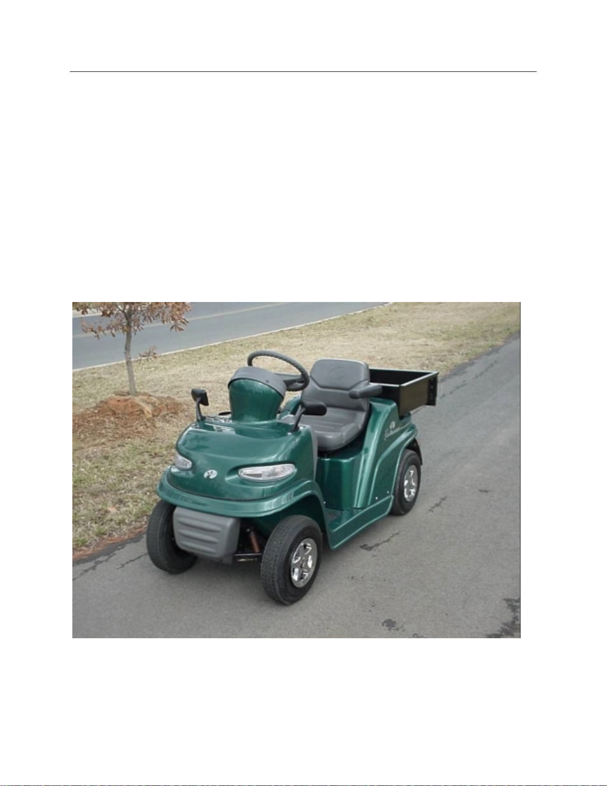
The FunRunner is an all-electric utility vehicle.
The energy for the FunRunner’s propulsion as
well as the operation of its lights, instruments,
horn, and etc., come from its 48-volt battery
pack. Being electric, the FunRunner emits no
exhaust and is therefore a zero emissions
vehicle. It is an environmentally friendly vehicle.
The FunRunner is also much quieter than an
internal combustion vehicle. It is well suited for
use in areas that are considered noise sensitive
or indoors where harmful gasoline emissions are
a concern.
Because gasoline powered vehicles have
electrical systems for cranking, ignition, lights,
etc., some of the service procedures used with
them are similar to those used with the
FunRunner. Other procedures will be unique to
the FunRunner.
The main components of the FunRunner are the
battery pack, electric motor, controller, battery
charger, and instrument cluster. The
FunRunner uses a 48V battery pack that is
considered to be high voltage.
voltage can be dangerous and requires an
extra measure of safety procedures not
normally associated with the service of
gasoline vehicles and equipment.
The high
Figure 1-1: FunRunner
1-1
Page 6

1-2
Page 7
SECTION 2: COMPONENT DESCRIPTION
Battery Pack
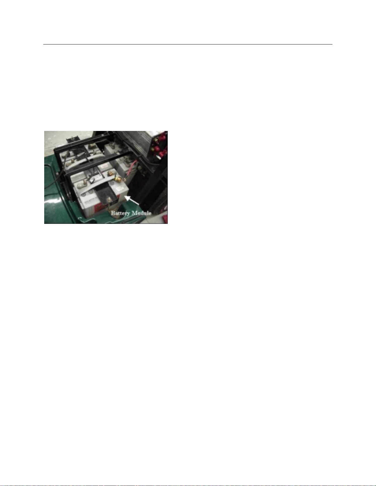
The battery pack of the FunRunner consists of
four 12-volt sealed lead acid battery modules.
The modules are situated in the vehicle under
the seat and are covered by the rear body panel.
See Figure 2-1. Since the modules are sealed
and valve regulated, no water or electrolyte can
be added to the batteries.
Figure 2-1:
Each module has a rated capacity of 73 amperehours (Ah) at a 20-hour discharge rate and 48
Ah at the 1-hour discharge rate. The capacity is
the available quantity of electricity in a battery
measured in Ah. Capacity is always related to
some quantity of current in amperes (amps) and
the length of time that the given current can be
produced. The minutes of reserve is a capacity
rating in which the amount of current is set at a
given rate, usually 25 amps, then the length of
time it takes for the battery to reach its
discharged cut-off voltage is measured. This
amount of time in minutes is the reserve
capacity of the battery.
For an electric vehicle like the FunRunner, the
capacity available from the batteries determines
the range of the vehicle. The range is the
distance that can be driven on one battery
charge.
temperature for rating a battery is 78°F. At
temperatures above 78°F, the capacity will be
higher than the rated capacity. The capacity will
be lower than rated capacity when temperatures
are below 78°F. At 32°F only about 70 percent
of the rated capacity is available. This is
significant, because if the FunRunner is
operated when the temperature is around 32°F,
the range will be reduced by 30 percent.
Another factor effecting capacity is the rate of
discharge. The battery modules in the
FunRunner are rated at 73 Ah for the 20-hour
rate and 48 Ah for the 1-hour rate. That’s a
large difference in the available Ah’s produced
between the two discharge rates. At the 20-hour
rate, the current drawn from the battery is set to
a low value that will take 20 hours to bring the
battery down to its cut-off voltage. The rate of
current in amps times the 20 hours is the
capacity rating. At the 1-hour rate, the current is
set at a much higher rate to bring the battery
down to the cut-off voltage in one hour. With a
73 Ah rating for 20 hours and a 48 Ah rating for
1 hour, it is obvious that the higher the rate of
current draw, the lower the capacity.
The FunRunner will use current at a fairly high
rate, and the higher the rate the shorter the
range will be. If it is driven faster or up hill
frequently, then the current rate will be higher
and the capacity of the battery pack will be
reduced.
The normal chemical process in the battery over
time will reduce the amount of active material on
the plates of the battery. This reduction in active
material will cause a reduction in capacity. In
other words, as the battery ages and more and
more charge/discharge cycles have occurred,
the capacity of the battery will begin to
decrease. When the aging process of the
battery has caused a decrease in capacity so
that the FunRunner no longer has a useable
range, the batteries must be replaced.
The normal driving range of the FunRunner is
approximately 30 miles when the batteries are
performing at their rated capacity. The battery
capacity and therefore the range can be affected
by several factors however.
Temperature has a dramatic effect on a lead
acid battery’s capacity. The standard
The four battery modules of the FunRunner are
wired in series to form a 48-volt battery pack.
When connecting battery modules in series, the
voltage of the pack is the total of the modules in
the series string. See Figure 2-2.
2-1
Page 8
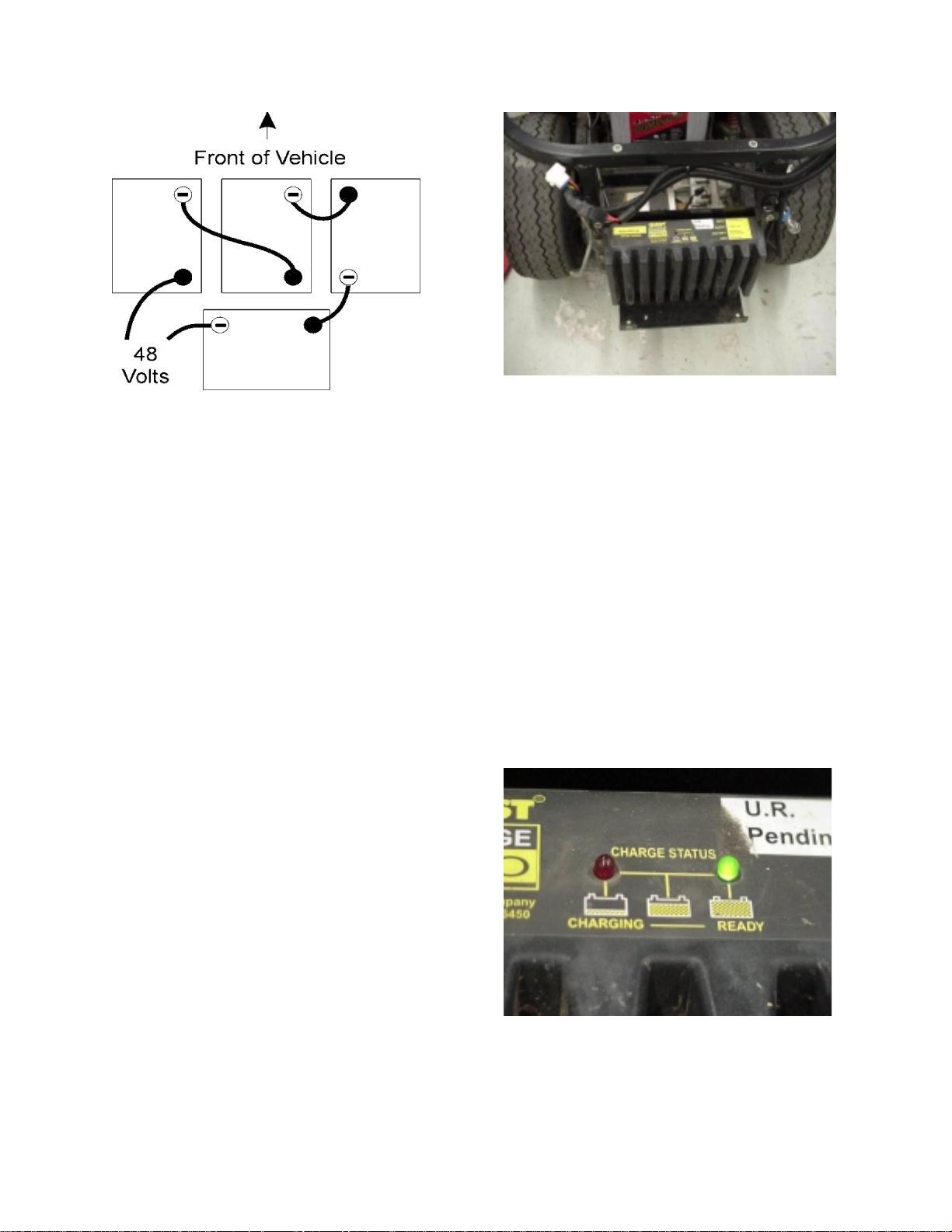
Figure 2-3:
Figure 2-2:
The modules must be connected from the
positive terminal of one module to the negative
terminal of the next. The one positive and one
negative terminal remaining on the modules are
the main terminals. The voltage at the main
terminals is 48V nominal.
When battery modules are connected in series,
the voltage of the system is added (i.e. 48 volts)
and the capacity of the modules not added. The
capacity of the series string is equal to the
capacity of one module. In fact, the capacity of
the series string is actually equal to the module
with the least capacity. However, because the
voltage is four times higher, the power and
energy of the pack is four times that of one
module.
As the capacity of the battery is reduced by the
various factors, the power of the battery is
normally not effected. The energy (power used
over time) is reduced however. This means that
no loss of speed, acceleration, or feel of power
will be experienced when a battery pack’s
capacity is reduced. A battery pack with only 15
Ah capacity wi ll have the same power as one
with 48 Ah capacity when both are fully charged.
What will be noticed is a reduction in the range
of the vehicle.
The charger receives its power from a 110 VAC
outlet when a cord is plugged into the charger
input connector located in the front of the rear
body panel below the seat. The AC power is
converted to DC and conditioned to the proper
voltage and current output levels to charge the
battery. It will take the charger about 7-8 hours
to restore a battery pack from fully discharged to
fully charged.
Located on the top of the battery charger are
one green and one red LED. See Figure 2-4.
During charging, the red LED is illuminated.
When the battery pack reaches a full charge, the
green LED will come on and the red LED will go
out. These LED indicators are not visible unless
the trunk basket panel is removed. The battery
charge gauge on the instrument panel cluster is
the indicator normally used for state of charge
reference.
Battery Charger
The FunRunner has an on-board battery charger
located at the rear of the vehicle just in front of
the rear bumper. See Figure 2-3. The function
of the charger is to replenish the used energy
from the battery pack.
Figure 2-4:
The battery charger is designed to never
overcharge or overheat the batteries due to
prolonged charging. Leaving the charger
plugged in will allow it to maintain a full charge
2-2
Page 9
without overcharging. It is desirable to leave the
charger plugged in for long periods periodically
to equalize the charge of the battery pack
modules. Doing this will increase batt ery life.
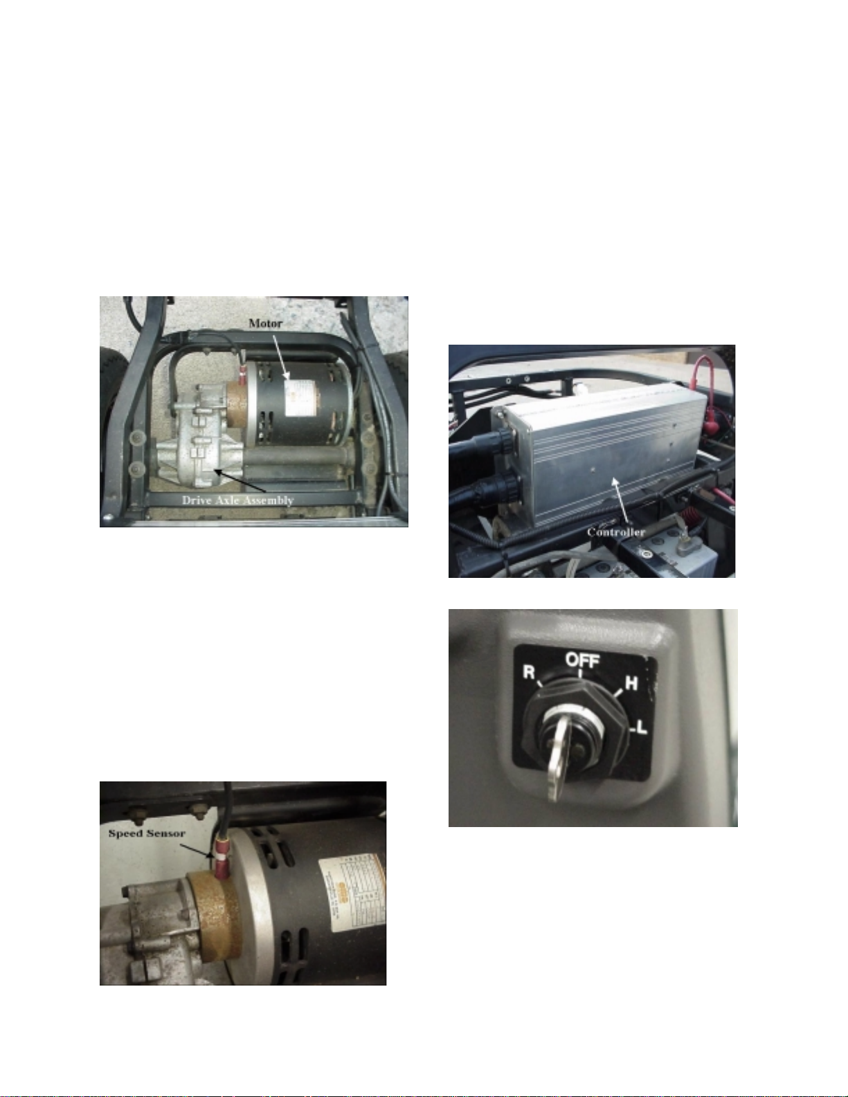
Electric Drive Motor
The FunRunner uses a 48-volt brush type DC
motor. The motor uses permanent magnets for
the field and has a wound armature with a
commutator that the brushes ride on. See
Figure 2-5.
Motor Controller Assembly
The motor controller assembly on the
FunRunner is located just ahead of the trunk
basket panel under the rear body section. See
Figure 2-7. The controller is rated at 150 amps
and 48 volts. It is a four-quadrant controller that
uses pulse width modulation. The four-quadrant
design allows the motor to be reversed,
eliminating the need for a mechanical reverse
gear. The pulse width modulation ensures
smooth acceleration and power de li very while
operating at an extremel y high effic ienc y level.
Figure 2-5:
The motor is connected to the rear wheels
through a fixed ratio drive axle with differential.
Reverse for the FunRunner is accomplished by
reversing the direction of rotation of the electric
drive motor. There are no reverse gears in the
drive assembly. The motor receives power from
the controller.
The motor has no serviceable parts and is
replaced as an assembly if it fails. There is a
speed sensor located on the spacer between the
motor and drive axle. The speed sensor is
supplied as a service part. See Figure 2-6.
Figure 2-6:
Figure 2-7:
Figure 2-8:
The controller can be switched to either high or
low forward speeds or reverse. See Figure 2-8.
When selected to high speed, the controller will
allow a maximum speed of 12 mph. In low
speed mode, the controller will reduce the output
voltage as needed to reduce the max speed to 8
mph. Reverse mode is 6 mph maximum.
2-3
Page 10
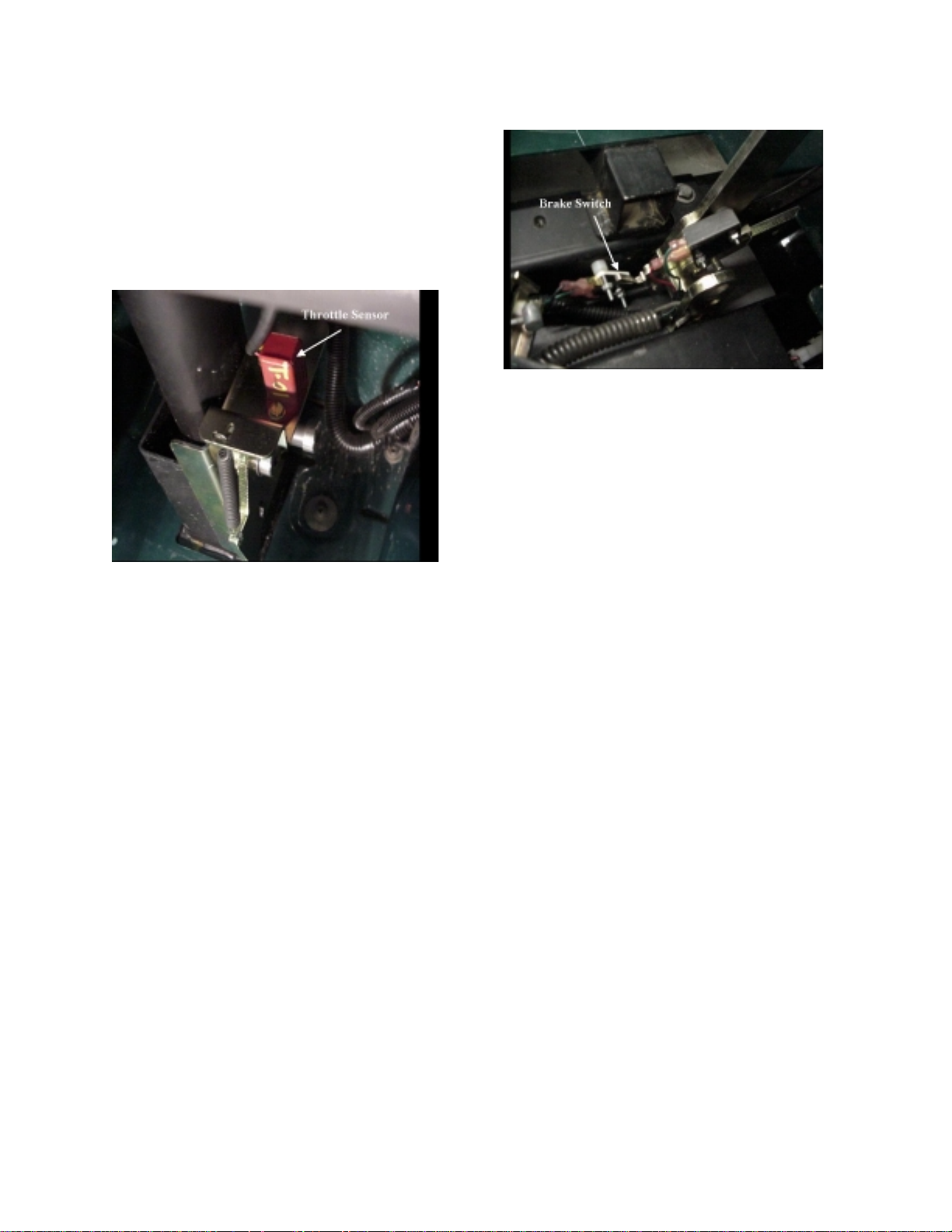
Of course, the controller must be able to provide
fully variable speed in each drive mode. The
throttle sensor is attached to the accelerator
pedal assembly and wired as an input to the
controller. See Figure 2-9. The sensor is a
potentiometer (a type of variable resistor often
called a pot) that will give a continual ly variable
signal from the fully released to fully depressed
pedal positions.
Figure 2-9:
The controller will monitor the throttle sensor
signal and adjust the output voltage to the motor
according to the demands of the operator
through the accelerator pedal.
The controller is also equipped with regenerative
braking. Regenerative braking is a feature
where the motor becomes a generator when the
vehicle is coasting or stopping. The kinetic
energy of the vehicle is turning the armature of
the motor through the permanent magnet field
producing a current in the armature that goes to
the controller. The current produced is opposite
of that used by the motor to drive the vehicle.
The controller will pass this current to the battery
pack replenishing a small portion of its charge.
The regenerative braking provides two benefits:
it increases range by adding some charge to the
battery pack and provides braking action that
assists the mechanical brakes. You can feel the
regenerative braking when re le asing the
accelerator even if the brake pedal is not
depressed.
The brake switch is connected to the controller
so that when the controller sees an input
indicating the brake has been depressed, it will
not allow power to flow to the motor even if the
accelerator pedal is depressed. See Figure
2-10.
Figure 2-10:
A signal is sent from the charger to the controller
during charging of the FunRunner. When the
controller senses the charging signal, none of
the propulsion modes can be activated. The
output from the charger passes thru the
controller to the batteries.
The FunRunner’s motor controller is unique in
that it controls all of the electrical systems on the
vehicle in addition to the motor. The controller
supplies power to each electrical system when
an input to the controller for the particular
system is activated. You can think of the
controller as a relay for each system. It
operates in a manner similar to a starter relay
connecting power to the starter when the ignition
or start switch energizes the coil of the relay.
An example of this would be the headlights.
The controller sends a voltage to the headlight
switch and monitors this voltage to see if it is
returned (pulled low) by the switch. When the
headlight switch is turned on, it closes
connecting the voltage to the return and the
controller sees the headlight switch wire pulled
low. The controller responds by supplying 12
volts to the headlight and taillight bulbs. The
headlight switch does not feed power directly to
the lights.
Other systems such as turn signals, brake lights,
hazard lights, horn, parking brake indicator and
etc., are controlled in the same way. These are
systems activated by the person operating the
vehicle. The controller will give outputs to other
electrical systems based on inputs not activated
by the operator. Examples are the state of
charge gauge and the speedometer. The
controller will adjust the state of charge meter
based on battery pack voltage. The controller
2-4
Page 11
will output a signal to the speedometer based on
an input from the speed sensor.
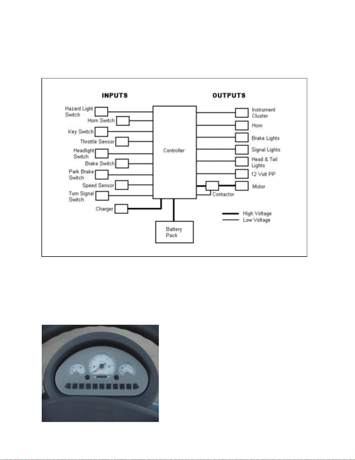
All of the controller inputs and outputs are
shown in Figure 2-11. The diagram shows how
the controller is the master of the electrical
systems on the FunRunner.
Figure 2-11
Instrument Cluster
The instrument cluster has three indicator
gauges across the top and several LED
indicators along the bottom of the cluster. See
Figure 2-12. The cluster is the inform ation
center for the operator.
Figure 2-12:
The center gauge is a speedometer with
odometer. The temperature gauge is on the left
and it displays the temperature of the controller
heat sink. The battery gauge is on the right side
and it displays the state of charge of the battery
pack.
The fault, temperature, battery, reverse, on,
high, low, charging, park brake, and headlights
indicators make up the bottom row of LED’s.
Above these indicator lights are the turn signal
indicators. These lights will illuminate when the
corresponding signal of its function is activated.
The fault, battery, charge, and temperature
indicators and an audible beep from the
controller are used to relay fault codes.
2-5
Page 12

2-6
Page 13
SECTION 3: ELECTRICAL AND CHEMICAL SAFETY
Electrical safety is foremost on the FunRunner,
since voltage levels present can cause severe
burns, shock, or death.
High voltage electric shock can cause muscle
contractions. A current of only 10mA can cause
muscles to contract. Hands that are exposed to
enough electrical current clinch
release their grip.
Even a small amount of current can cause body
tissue damage. Damage to tissue is caused by
heat generated from current flow. When the
heat passes a point where it can be dissipated,
the body tissue is burned.
Fibrillation
heartbeat, can be caused by electrical shock.
The current must pass through the body, such
as with a hand-to-hand connection, in order for
fibrillation to occur.
Arcing
across a circuit gap. The heat at the ends of an
arc can be four times the surface temperature of
the sun. Severe burns can be caused when a
person is near or in contact with an arc.
An arc can cause an electric
the expansion of the air and molten metal,
usually copper, from the rapid heating taking
place.
, the disruption of the body’s normal
occurs when electricity is discharged
tight and cannot
blast
. The blast is
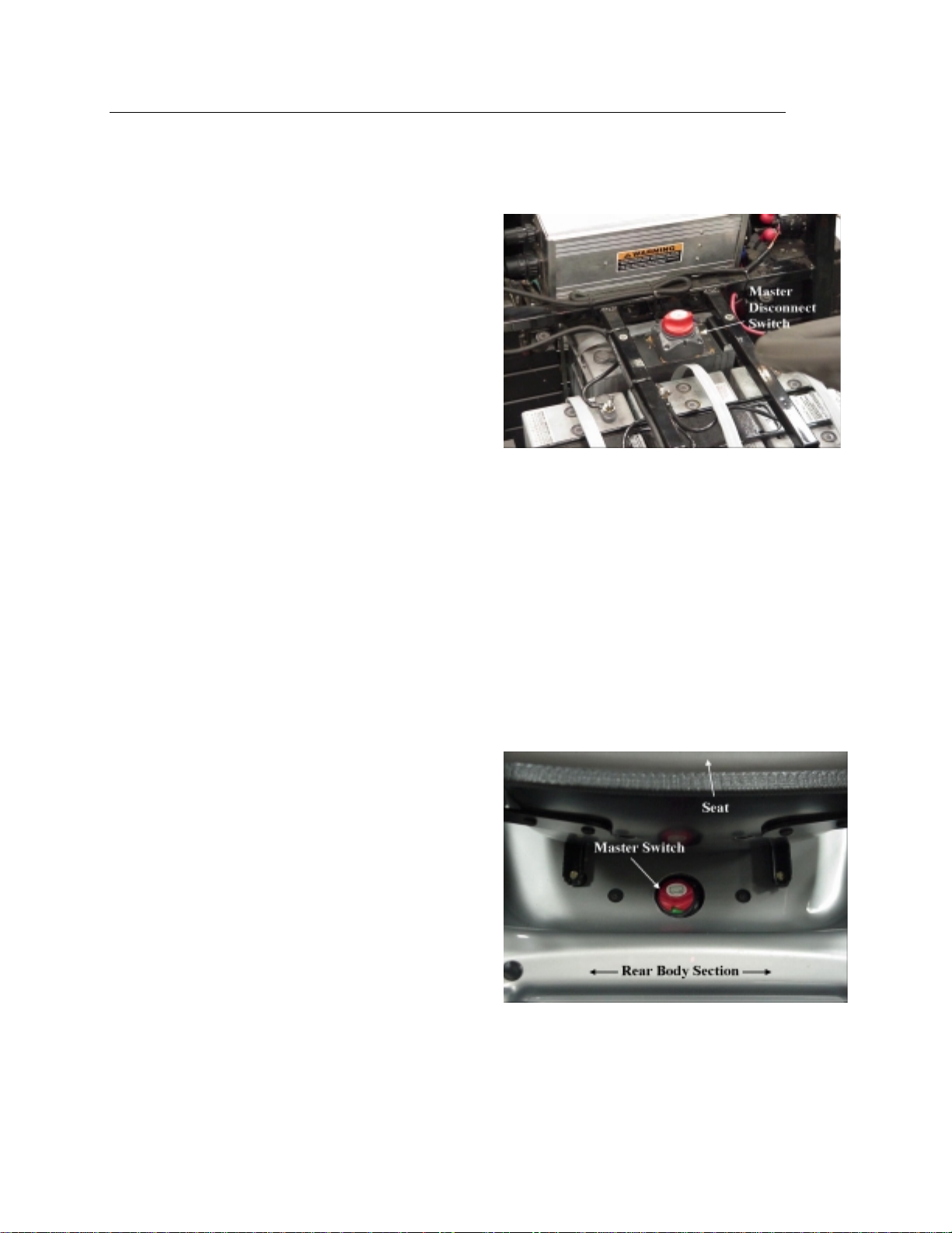
The FunRunner is equipped with a master
disconnect switch. See Figure 3-1.
Figure 3-1:
The master switch is a safety device that allows
the battery pack voltage to be removed from the
controller. The switch is to be used to
disconnect the battery from the controller before
starting any repairs to the high voltage portion of
the vehicle.
The master switch is located behind the seat.
See Figure 3-2. It can be turned off by sliding
the seat forward, reaching behind the seat and
twisting the red knob. The knob can be pulled
off of the switch when in the off position to
ensure that it is not inadvertently turned back on.
High Voltage Safety Procedures
The FunRunner’s high voltage and low voltage
systems are isolated from chassis ground under
normal circumstances. You must touch both a
positive and negative point in the circuit in order
to receive an electric shock. You should never
ground any wire on the FunRunner to the
chassis. Doing so could put the operator and
any service personnel in danger.
Figure 3-2:
The FunRunner has high voltage in the
propulsion, charging and ignition switch circuits.
See Figure 3-3.
3-1
Page 14
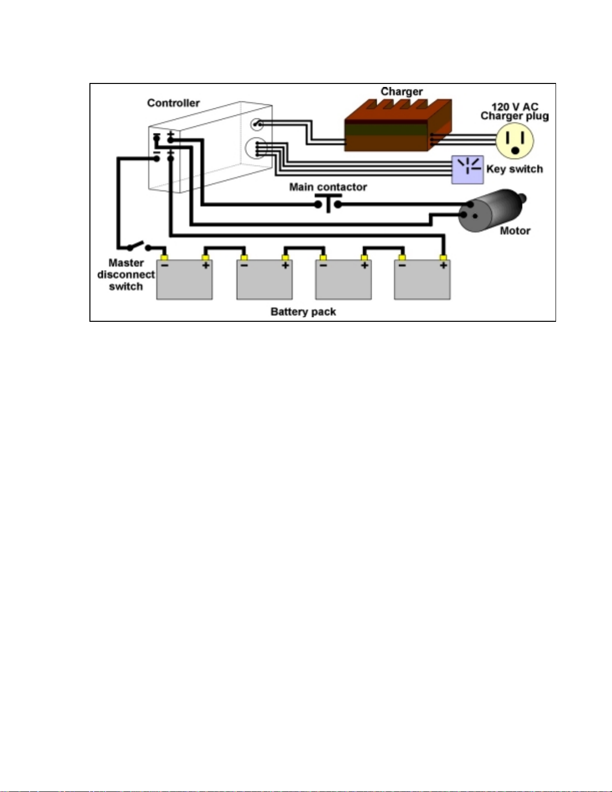
Figure 3-3: FunRunner High Voltage Wiring
Practicing safety around hig h vol tage (HV)
will protect you and those around you. Keep
in mind the following HV safety precautions:
•
Have ample light in the work area.
•
Do not work in wet or damp areas.
•
Use proper tools, equipment, and
protective devices.
•
Remove all jewelry and metallic items.
•
Keep your tools and equipment in good
condition.
•
Never assume that voltage is not
present; check it with a known good
meter or other test device.
•
Verify that any capacitors have been
discharged.
•
Never try to bypass or override a safety
device, such as a fuse, unless specified
to do so with an approved tool as
described by the manufacturer’s
procedures.
•
Always use the correct replacement
parts.
•
Never use water on an electrical fire;
have an approved fire extinguisher
available.
•
Use only one hand when possible.
•
Wear eye protection.
•
Never work on high voltage when you
are totally alone; someone else should
be present in case an emergency
arises.
•
Follow the manufacturer’s procedures.
•
Take your time, think first and do not
rush.
•
Know emergency policies and
procedures for your work area.
•
Wear natural fabric clothing such as
cotton; polyester clothing will melt to
the skin when exposed to electrical
arcs.
•
Use insulated tools and inspect them
regularly for damaged insulation.
•
Know where eyewash stations, fire
extinguishers, reach poles and other
safety equipment is located.
•
Never lay tools or any conductive
material on any HV component or
battery pack.
The longer someone is in contact with an
electrical current, the less chance there is
for survival. The victim may stop breathing
and become somewhat stiff. In the case of
electrical shock, the following procedures
should be followed:
•
Call 911 or the appropriate emergency
numbers for your area.
•
Break the electrical connection as
quickly as possible, but do not expose
yourself to any electrical current.
•
If the current cannot be removed, use a
fiberglass reach pole or a dry board to
separate the victim from the circuit. Do
not touch the victim with your bare
3-2
Page 15

hands until you are sure they have
been removed from the electrical
current.
•
If the victim has stopped breathing or
his/her heart is not pumping, use CPR
until help arrives. Only a trained
person should administer CPR.
•
If the victim must be moved, take
precautions in doing so. Use a
stretcher if possible.
Fire is always a possibility when working on
an electric vehicle. High voltage and
chemical batteries have the potential to
cause both fire and explosion when a faulty
condition exists.
Work areas should be clean and not
cluttered with combustible materials.
Flammable liquids should be stored in
approved storage areas.
You should know the location of fire
extinguishers and fire alarms. You should
also know how to contact the fire
department. Make sure you know how to
operate the fire extinguishers and what type
of fire they are rated for. Figure 3-4 shows
the classes of fires. Fire extinguishers
should be inspected monthly to verify they
have a full charge.
Figure 3-4:
eyes. The neutralizing agent for sulfuric
acid is bicarbonate soda. One pound of
soda dissolved in one gallon of water makes
a good neutralizing solution that can be
used in a spray bottle or poured on a spill.
When sulfuric acid contacts the skin, eyes,
or clothing, the first line of defense is water
and plenty of it. Flush the area with clean
water and soda mixture for 15 minutes. If
there is not enough soda-water mixture to
flush for 15 minutes, continue to flush with
clean water for a minimum of 15 additional
minutes and get prompt medical atten tio n.
If acid is accidentally swallowed, drink large
quantities of milk or water, followed by milk
of magnesia, a beaten egg, or vegetable oil.
Consult a physician immediately.
Chemical Safety
Batteries in the FunRunner contain
electrolyte that is very corrosive. Contact of
electrolyte with skin or eyes should be
avoided.
The FunRunner uses sealed batteries that
contain electrolyte in a gel between the
plates. While these types of batteries
cannot spill large amounts of electrolyte,
care should still be taken to avoid chemical
contact with the skin and eyes.
When working around batteries where there
is the possibility of chemical exposure, eye
protection should be worn, rubber gloves
and a rubber apron are recommended. An
emergency shower and eye wash stat ion
should be available as well as a first-aid kit
and electrolyte neutrali zing solu tio ns .
Lead acid batteries have a sulfuric acidwater solution as the electrolyte. Sulfuric
acid is very corrosive and can burn skin and
3-3
Page 16

3-4
Page 17

SECTION 4: REMOVAL & INSTALLATION
Canopy................................................................4-3
Utility Bed............................................................4-7
Motor/Speed Sensor...........................................4-9
Motor Contactor ................................................4-15
Controller ..........................................................4-19
Battery Modules................................................4-23
Battery Charger.................................................4-29
Lights ................................................................4-33
Headlight, Horn, Hazard Light Switches............4-35
High/Low/Reverse Switch..................................4-37
Turn Signal Switch............................................4-39
Accelerator Pot (Throttle Sensor)......................4-41
Instrument Cluster.............................................4-43
Park Brake Switch.............................................4-45
Brake Light Switch.............................................4-47
Horn..................................................................4-51
4-1
Page 18
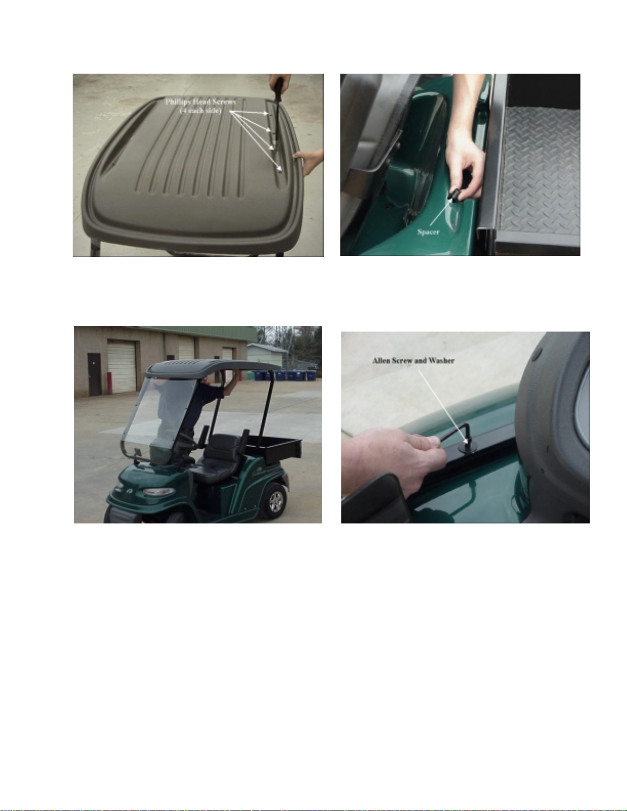
Figure 4-1
Figure 4-2 Figure 4-3
Figure 4-1A
4-2
Page 19

SECTION 4: CANOPY INSTALLATION & REMOVAL
PARTS REQUIRED
710-0642 Hex Washer Screw 1/4-20 x .75 (8)
736-0342 Flat Washer .283 ID x .75 OD (12)
731-2337 Canopy Panel
749-1265 Rear Canopy Frame
749-1266 Front Canopy Frame
710-0136 Hex Cap Screw 1/4-20 x 1.75 (2)
710-1122 Hex Cap Screw 1/4-20 x 2.5 (2)
750-1298 Spacer .280 ID x 437 OD x .250 Lg (2)
750-1299 Spacer .280 ID x 437 OD x .850 Lg (2)
TOOLS REQUIRED
Phillips head screwdriver - #2
3/16” Allen wrench
Note: you may need one person to help.
STEP DETAILS
Get tools and check parts. See list above.
Assemble molded canopy and supports
(Figure 4-1).
Install canopy and support assembly.
Note: Nylon bushings are installed between
the vehicle body and the threaded screw
holes used to fasten the canopy supports.
Be careful to place bushings in position
properly.
Note: Screws have spacers under
canopy supports that must be installed to
protect body from deflection (Figure 1A).
Align screw holes with holes in supports.
Install and tighten Hex washer screws with
flat washers through canopy into threaded
holes in supports.
Remove two cap plugs on top of body just
behind seating area.
Remove two Allen screws and spacers on
top of body directly in front of the dash.
Insert the shorter spacers in the front holes
and the longer spacers in the rear holes.
Gently set canopy/support assembly on
vehicle with curved end facing to the front.
(Figure 4-2).
Insert and tighten Hex cap screws with flat
washers in front and rear supports. Tighten
to 65 to 75 in. lbs. (Figure 4-3).
Save extra parts. Store Allen screws for use if top is removed.
4-3
Page 20

4-4
Page 21

Remove canopy assembly. Remove 4 Hex cap screws from supports and
set canopy assembly aside.
Remove spacers and store screws.
If canopy assembly is not to be replaced, place
cap plugs in rear body section and install
original Allen screws and spacers in front body
panel
Remove molded canopy.
Note: If canopy is to be re-installed, this step
is not necessary.
Remove 8 Phillips head, ¼” x ¾” screws from
canopy.
Lift canopy from supports and set aside.
Store screws for replacing canopy.
4-5
Page 22

Figure 4-4
Figure 4-5
Figure 4-6
4-6
Page 23

UTILITY BED INSTALLATION
PARTS REQUIRED
607-0013 Utility Box Assembly
710-1832 Machine Screw 1/4-20 x 2” (4)
736-0173 Flat Washer .28 ID x .74 OD (4)
#2 Phillips screwdriver
1/16” Allen wrench
STEP DETAILS
Remove rear trunk lid and trunk basket
(Figure 4-4).
Remove body retaining screws
(Figure 4-5).
Raise cover so hinge rod is visible.
Loosen 1/16” Allen set screw on each hinge rod
locking collar.
Slide hinge rod toward one side to remove rod,
spacers and trunk lid.
Be careful not to loose spacers. Remove trunk
basket.
Remove 4 Phillips head screws and washers
holding body to frame around storage area.
Disconnect trunk lock from back of vehicle by
removing the two cap screws.
TOOLS REQUIRED
Store screws for possible future use.
Install utility bed (Figure 4-6). Place bed on frame so tailgate is to the rear.
Line up holes in bed with holes in frame.
Install 4 screws and flat washers provided
through bed into frame.
Tighten screws to 40-45 in. lbs. and check bed
secure.
Clean up. Store parts and tools.
4-7
Page 24
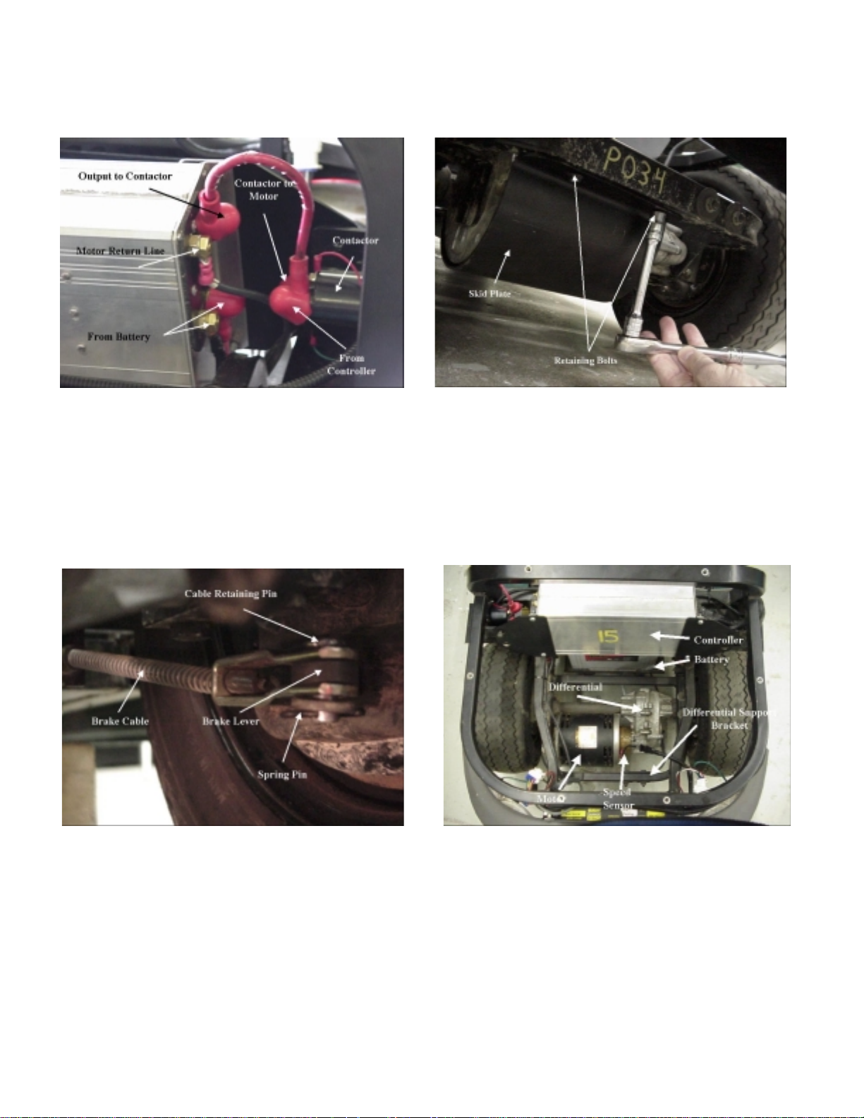
Figure 4-7
Figure 4-8
Figure 4-9
Figure 4-10
4-8
Page 25

MOTOR/SPEED SENSOR REMOVAL & INSTALLATION
TOOLS REQUIR ED
Wrenches - 3/8”, 1/2”, 9/16”, and 5/8” - socket and box end preferred
Pliers
Lift or jack - suitable for raising rear of vehicle and being clear when axle/wheel assembly is slid
out to the side.
Phillips screwdriver - #2
Allen wrench – 3/16”
STEP DETAILS
Make vehicle safe and accessible.
WARNING:
IF MASTER POWER SWITCH IS NOT OFF
BATTERY IS STILL CONNECTED TO
CONTROLLER. USE EXTREME CARE TO
AVOID INJURY OR DAMAGE.
Turn master power switch to off. Key operated switch mounted below
Disconnect motor cables from contactor and
controller (Figure 4-7).
Note: use care that washer or nut cannot fall
into motor.
Remove skid plate (Figure 4-8). From under motor.
Make sure switch is off and key removed.
Place chocks under all 4 wheels, front and
back of each wheel if any chance of rolling.
Remove utility bed if installed (4 screws)
Remove storage compartment.
controller.
Disconnect motor lead from motor side of
contactor.
Move controller as necessary to reach left side
power cable terminals.
Disconnect top-front power cable on lef t sid e
of controller (goes to motor).
Front cable connected with 9/16” nut and star
washer. (rear cable connected with 5/8” nut
and star washer. Do not remove for this step).
Fastened to frame in front and rear of motor
with 4 screws, ¼” x ½” with 3/8” hex head.
.
Disconnect brake cables (Figure 4-9). From rear brake levers, right and left rear
wheels.
Pull spring pins from brake cable retaining
pins.
Lift retaining pins from cable shackles.
Disconnect speed sensor. Unfasten differential
support bracket (Figure 4-10).
Unplug (plug in line inside rear compartment).
Bracket is bolted to frame with two large
washers on outside of frame.
4-9
Page 26
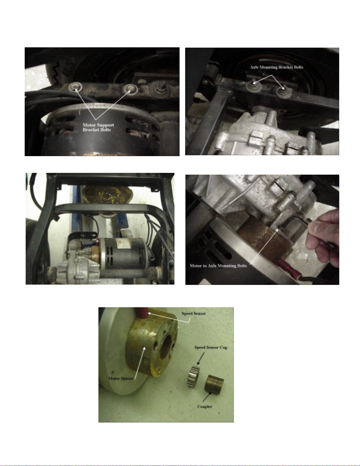
Figure 4-11
Figure 4-12
Figure 4-13
Figure 4-14
Figure 4-15
4-10
Page 27

Warning:
After axle assembly is completely loosened,
motor can fall and catch a hand unless care
is used. Suggest a block be placed under
differential bracket before axle is completely
loosened.
Disconnect motor support bracket
(Figure 4-11).
Bolted to motor and frame on left side of
vehicle.
2 bolts, ¼” x ½” - need 3/8” wrench.
Remove axle mounting brackets
(Figure 4-12).
Slide axle assembly from under vehicle
(Figure 4-13).
Remove motor (Figure 4-14). Place support under motor.
Remove parts from motor. Slide coupler and speed sensor cog from
Need ½” box end and ½” ratchet wrenches.
Attach lift to rear of frame, or use floor jack,
and raise vehicle high enough to slide rear
axle/motor assembl y out to side.
Place supports under rear of battery pack to
be sure vehicle cannot fall.
Use 3/16” Allen wrench to remove two
mounting screws.
Tilt rear of motor down and remove from drive
axle.
motor shaft.
Remove motor support bracket -two bolts -
3/8” wrench.
Loosen 1/8” Allen screw in end of spacer and
unscrew speed sensor.
Install parts on new motor (Figure 4-15). Bolt motor support bracket to new motor.
Insert speed sensor cog and coupler into
spacer and onto new motor shaft.
Install speed sensor in spacer.
Set speed sensor depth. Make sure speed sensor cog is inserted on
motor shaft
Screw speed sensor into spacer until it
touches cogs on sensor gear.
Unscrew speed sensor ¾ to 1 turn and make
sure it does not touch cogs when motor turns.
Tighten set screw to lock speed sensor in
place. Caution: do not over tighten set screw
causing damage to sensor threads.
4-11
Page 28
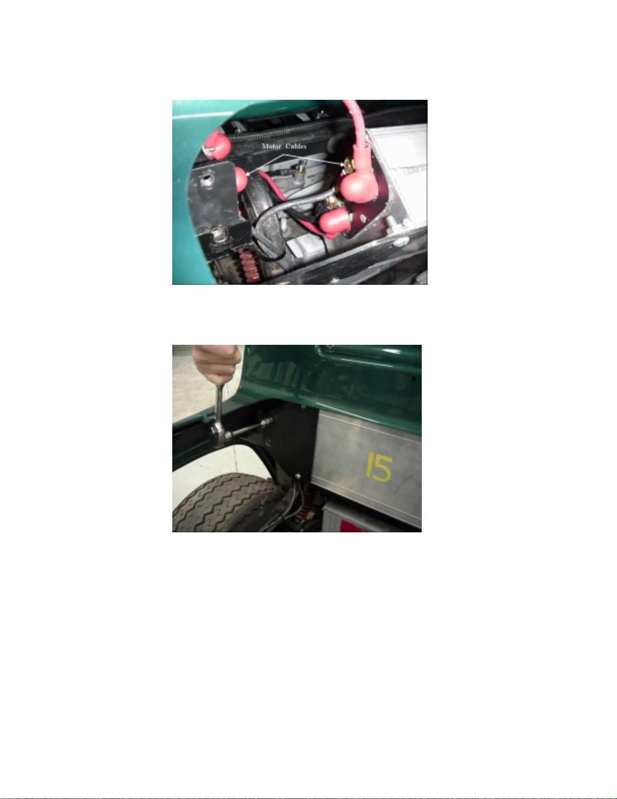
Figure 4-16
Figure 4-17
4-12
Page 29

Install new motor on axle assembly. Place motor on support so differential can be
rotated and lined up with motor.
Mate motor to differential with speed sensor
pointing away from axle. Make sure speed
sensor cog and coupler are in place.
Replace motor mounting screws using 3/16”
Allen wrench. Tighten securel y.
Mount axle assembly on vehicle. Slide assembly under rear of vehicle and
locate close to proper position.
Place block under differential support bracket
so bracket will be in position when ve hic l e is
lowered.
Lift vehicle slightly and remove supports from
under battery pack.
Slowly lower vehicle while adjusting position of
axle assembly so assem bl y will be in proper
position when vehicle is com pletely down on
the axle.
Bolt differential and motor supports to frame.
Install axle mounting brackets and tighten.
Connect brake cables. Place pins, from the top, through shackles and
brake levers.
Insert spring pins into brake connecting pins.
Connect motor power cables (Figure 4-16). Negative cable goes to top-front terminal on
left side of controller.
Positive cable with red terminal cover goes to
terminal on motor side of contactor.
Mount controller (Figure 4-17). Bolt mounting plates to frame (4 bolts).
Connect speed sensor. Plug into connection inside rear compartment.
Test unit. Turn on master power switch and test for
normal operation.
Install utility bed (if appropriate). Line up 4 bolt holes, install and tighten bolts.
4-13
Page 30
Mounting
Mounting
Screws
Screws
From
From
Controller
To
To
Motor
Motor
Figure 4-18
Figure 4-20
Activation Wire
Activation Wire
Terminals
Terminals
Figure 4-19
Figure 4-21
From
From
Controller
Controller
Figure 4-22
4-14
Page 31

MOTOR CONTACTOR REMOVAL & INSTALLATION
STEP DETAILS
Make sure vehicle is safe. Switch off and key removed.
Parking brake set.
Remove canopy assembly (if installed).
Remove utility bed (if installed). Remove 4 Phillips head screws.
Lift bed off and set aside.
Turn off master power switch. Located behind seat.
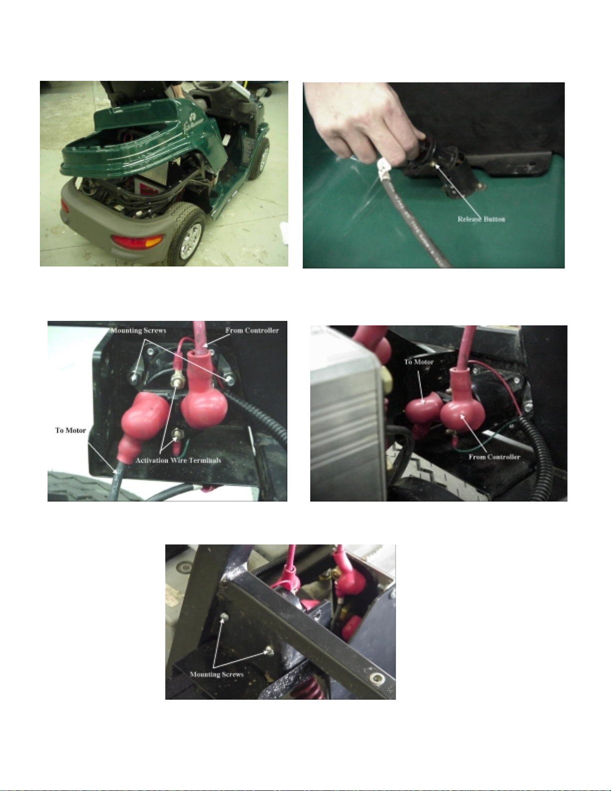
Remove rear body section (Figure 4-18). 4 screws at front below seat.
Two screws each side beside seat.
Two screws below rear of seat (over battery).
4 screws around top of storage compartment.
Lift rear of section and work it free. May have to
cut one or more electric tie wraps so section can
be lifted off without placing strain on charger
cable and plug.
Unplug charger power cable (Figure 4-19). Inside front of rear body section.
Press button in side of plug and disconnect.
Disconnect activation wire terminals
(Figure 4-20).
Disconnect cables from controller and to motor
(Figure 4-21).
Remove contactor (Figure 4-22). Note: two nuts will come loose and fall when
Connect cables to motor and from controller. Connect cable to motor then cable from
Connect activation wire terminals. In the same positions they were before (red
Remove nuts and note location of wires.
Slide terminal covers off.
Disconnect cable from controller then cable to
motor.
screws are removed.
Remove two common point screws on outside
of frame.
Slide contactor off the mounting screws to
inside of frame.
controller.
Slide terminal covers onto terminals.
lead near power cable from controller)
4-15
Page 32

4-16
Page 33

Test operation. Turn on master power switch (behind seat).
Make sure vehicle will operate properly.
Install parts removed. Install rear body section, utility bed and canopy
assembly.
4-17
Page 34

Figure 4-23
Figure 4-24
Figure 4-25
4-18
Page 35

CONTROLLER REMOVAL & INSTALLATION
TOOLS REQUIRED
Note:
It is
½” Socket wrench
9/16” wrench
5/8” wrench
# 2 Phillips screwdriver
STEP DETAILS
easier and safer
section and disconnect batteries before
removing/replacing controller
to remove rear body
Check vehicle safe status.
Warning:
Charged capacitors are present in controller.
As soon as switch is turned off press horn
switch until one capacitor discharges (horn
will whine and fade out).
Remove utility bed or storage compartment
(storage compartment lifts out).
Turn master power switch to off. Switch mounted below controller.
Remove controller mounting bolts (Figure 4-23). 4 - 5/16 x ¾” bolts holding controller supports
Disconnect two connectors (twist lock plugs)
(Figure 4-24).
Pull controller back (Figure 4-25).
Make sure switch is off and key removed.
Make sure vehicle will not roll while work is
being done.
If installed.
May be necessary to tie up rear compartm ent
cover or remove it.
to frame - 2 each side.
From right side of controller.
Carefully to the rear until power cable
terminals on left side are accessible.
Warning:
48 volts present in battery pack. Dangerous.
Be sure cable ends are kept from making
contact with frame, tools or with
battery terminals are disconnected
you
until
.
4-19
Page 36

Figure 4-26
Figure 4-27
Figure 4-28
Figure 4-30
Figure 4-29
Figure 4-31
4-20
Page 37

Disconnect motor and battery power cables
(Figure 4-26).
Note: it is a smart move to lay a cover over
the motor before removing cables. A loose
washer inside the motor is no fun.
Disconnect motor and battery power cables. Use 5/8” wrench for rear terminals and 9/16”
Check fuse in battery cable (Figure 4-27). If failure is possible cause of problem.
Get new controller. If replacement is necessary.
Insure master switch is off. Place
voltmeter across battery terminals on
controller and bleed charge off the second
capacitor installed in controller until
Two top cables are motor power output and
two bottom cables are from the battery.
wrench for front terminals.
Even though the front and rear studs are
different size, it might be a good idea to mark
cables for future reference.
Use ohmmeter. Should show very little
resistance.
Warning:
voltage is below 5v.
Connect battery cables (Figure 4-28). To two bottom terminals on controller.
Note: most terminal studs are soft metal. Do
not over tighten.
Connect motor power cables (Figure 4-29). To two top terminals on controller.
Connect twist lock plugs (Figure 4-30). To receptacles on right side of controller.
Work controller into position and bolt in place
(Figure 4-31).
Turn on master power switch.
Replace parts previously removed. Rear body and canopy if appropriate.
Check vehicle. For loose fastenings, missing parts, etc.
Might require some “wiggling” so be patient.
Replace 4 hex head 5/16” x ¾” bolts holding
supports to frame.
Utility bed or storage compartment.
Check for proper operation.
4-21
Page 38

Figure 4-32
Figure 4-33
Figure 4-34
4-22
Page 39

BATTERIES REMOVAL & INSTALLATION
STEP DETAILS
Make sure parts on hand. Batteries (total of 4 in vehicle)
Deka - “Dominator”
Model 8G24 - 12v
Get required tools. #2 Phillips screwdriver
5/8” wrench
9/16” wrench
1/2” ratchet wrench
Insulated pliers
3/16” Allen wrench
Make vehicle safe. Switch off and key removed.
Parking brake set.
Remove canopy assembly. If installed.
Remove utility bed. If installed.
4 Phillips screws.
Note: if utility bed not installed, lif t stor age
container from rear compartment.
Turn off master power switch. Located behind seat.
Remove rear body section (Figure 4-32) and
(Figure 4-33).
Unplug charger power cable (Figure 4-34). Inside front of rear body section.
4 screws at front below seat.
Two screws each side beside seat.
Two screws below rear of seat (over battery).
4 screws around top of rear compartment
(same screws used to mount utility bed).
Lift rear body section and work it free. May
have to cut one or more electric tie wraps so
section can be lifted off without placing strain
on charger cable and plug.
Press button on side of plug and disconnect.
4-23
Page 40

Figure 4-35
Figure 4-36
Figure 4-37
Figure 4-38
Figure 4-39
4-24
Page 41

Disconnect batteries (Figure 4-35) .
Warning:
Batteries are probably charged and “hot”.
Use care to not short cables to frame or
other battery terminals.
Remove hold down bars. Two bars, one over front 3 batteries and one
Remove batteries (Figure 4-36). Do not let battery terminals short to frame.
Check fuse. If damage to fuse is suspected.
Replace batteries. Be sure rear battery positive terminal is toward
Disconnect cables going from battery to battery
first.
Loosen wing nuts and slide connectors off.
Disconnect cables from battery to controller
last.
over rear battery. Be careful not to short bars
across batteries.
Place insulation over all battery terminals if
necessary to prevent shorting (electrical tape if
nothing better available).
In the event the fuse is damaged, find the
cause before reconnecting batteries.
the right side, right front battery positive
terminal is on front of battery, and positive
terminals on other two on the rear of those
batteries (See Figure 2-2 in Section 2).
Replace hold down bars (Figure 4-37). Long bar between terminals, side to side,
across three front batteries and the short bar
across the rear battery.
Reconnect battery cables (Figure 4-38). Connect fused cable to positive terminal on left
front battery.
Connect other controller power cable from
master switch to negative terminal on rear
battery.
Connect rest of battery terminals in series
(positive on one battery to negative on the
next) (See Figure 2-2 in Section 2).
Connect charger cable (Figure 4-39). To receptacle in front of rear body section.
4-25
Page 42

4-26
Page 43

Install rear body section. Lift body section and work into position so
screw holes are lined up.
Replace electrical tie wraps if necessary to
hold cables.
4 screws at front below seat.
Two screws each side beside seat.
Two screws below rear of seat (over battery).
4 screws around top of storage compartment
(leave out if utility bed to be mounted).
Turn on master power switch. Located behind seat.
Operate vehicle. Make sure all parts are operating properly.
Install utility bed. Make sure spacers are in position to prevent
warping rear body section.
Insert and tighten 4 mounting screws.
Install canopy assembly. If appropriate.
Lift assembly into position so canopy support
mounting holes line up with mounting screw
holes in body.
Install and tighten mounting screws (2 ½”
screws in rear support, 2” screws in front).
Charge battery pack. Plug in charger and charge battery pack
overnight to balance the battery modules.
4-27
Page 44

Figure 4-40
Figure 4-41
Figure 4-42
Figure 4-43
4-28
Page 45

BATTERY CHARGER REMOVAL & INSTALLATION
STEP DETAILS
Get required tools. #2 Phillips screwdriver
½” wrenches (2)
Tool for cutting tie wraps
Note: charger cable runs from receptacle on
front of rear body section to charger mounted on
rear of vehicle frame.
Check machine safe. Switch off and key removed.
Set parking brake.
Remove canopy assembly and utility bed or
storage container.
Turn off master power switch. Located behind seat.
Remove rear body section (Figure 4-40). Remove all mounting screws.
If installed.
Lift body section off and disconnect charger plug
inside front of section.
Remove rear bumper (Figure 4-41) and
(Figure 4-42).
Remove charger (Figure 4-43). Cut all electrical tie wraps from charger cable.
Replace charger.
Caution:
Use care to not damage cables coming
out of the bottom of the charger.
Unplug tail light connections inside storage
compartment.
Remove 4 Phillips head screws.
Pull bumper off and lay aside.
Disconnect cable going from charger to controller
(connector plug on cable, from left bottom of
charger, inside storage compartment).
Unbolt charger from rear of vehicle frame (4
bolts).
Remove charger and cables.
Bolt charger to frame.
Run cable through to reach the front of the rear
body section when it is replaced.
Use electrical tie wraps to hold cable in position
clear of moving parts and frame.
Connect plug in cable from charger to controller.
4-29
Page 46

4-30
Page 47

Turn on master power switch. Located behind seat.
Test charger. Make sure it is actually sending current to battery
(voltage rises and charge status light comes on
when plugged in).
Replace rear bumper. 4 Phillips head screws.
Connect tail light cables inside storage
compartment.
Replace rear body section. Connect charger cable to receptacle inside front
of body section.
Lift body section into place and install screws.
Replace storage container or utility bed and
canopy assembly.
If previously removed.
4-31
Page 48
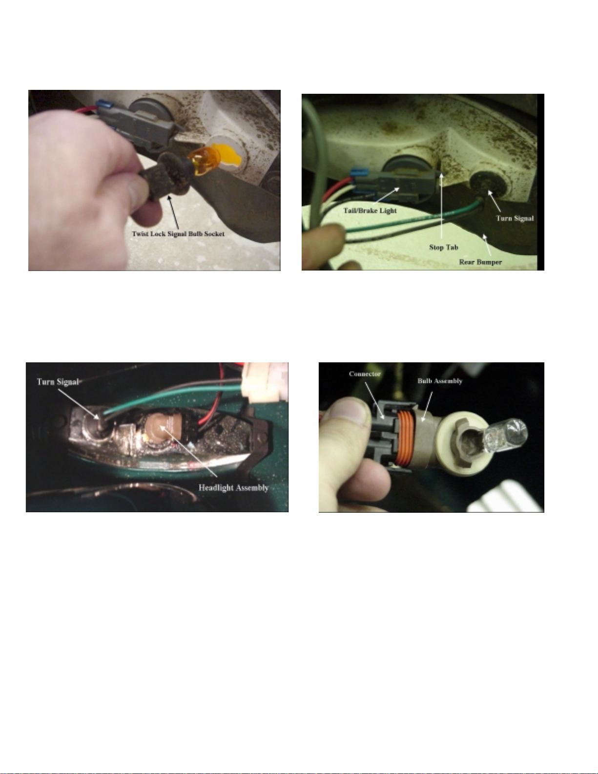
Figure 4-44
Figure 4-46 Figure 4-47
Figure 4-45
4-32
Page 49

LIGHTS REMOVAL & INSTALLATION
STEP DETAILS
Make vehicle safe. Switch off and key removed.
Parking brake set.
Replace turn signal bulb (Figure 4-44). Twist turn signal receptacle about ¼ turn
counterclockwise and remove from fixture.
Unplug bulb and replace.
Insert receptacle into fixture and turn clockwise
¼ turn into detent.
Replace tail/brake light bulb (Figure 4-45). Press locking tab down from inside slot and
rotate receptacle about ¼ turn to remove from
fixture.
Unplug bulb and replace.
Insert receptacle into fixture and turn clockwise
¼ turn until tab on receptacle contacts flange on
fixture.
Replace headlight bulb (Figure 4-46) and
Figure 4-47).
Check lights. Make sure new bulb is operating properly.
Rotate headlight assembly counterclockwise and
extract from fixture.
Release catches and unplug bulb assembly from
its base plug.
Replace bulb assembly.
Insert bulb assembly into fixture and rotate
clockwise until seated.
4-33
Page 50

Figure 4-48
Figure 4-49
4-34
Page 51

HEADLIGHT, HORN, HAZARD LIGHT SWITCHES
REMOVAL & INSTALLATION
STEP DETAILS
Check vehicle safe. Switch off and key removed.
Set parking brake.
Remove switch from panel (Figure 4-48). Reach behind panel and press switch
assembly out to the front of the panel
(driver’s side).
Disconnect switch (Figure 4-49). From wiring harness.
Release catches and unplug switch .
Replace switch. Plug in new switch and press assembly back
into panel.
Test operation. Check switch operating properly.
4-35
Page 52

Figure 4-50
Figure 4-51
4-36
Page 53

IGNITION SWITCH REMOVAL & INSTALLATION
STEP DETAILS
Make sure vehicle safe. Switch off and key removed.
Set parking brake.
Turn master power switch off (behind seat).
Warning:
Voltage is applied to the switch unless the
master power switch is off. Be careful.
Remove switch (Figure 5-50). Remove hex nut from switch at front of panel.
Pull switch out from rear of panel.
Unplug switch from jumper harness.
Install new switch (Figure 4-51). Plug into wiring harness.
Turn switch so key slot is oriented as desired
and insert switch through rear of panel.
Screw hex nut to front of switch until nut is
about the right position.
Adjust rear hex nut so switch is located at
right depth.
Tighten front nut.
Tie wrap excess wire so it is out of the way.
Turn master power switch on. Located behind seat.
Test unit. Make sure switch operates properly in all
positions.
4-37
Page 54
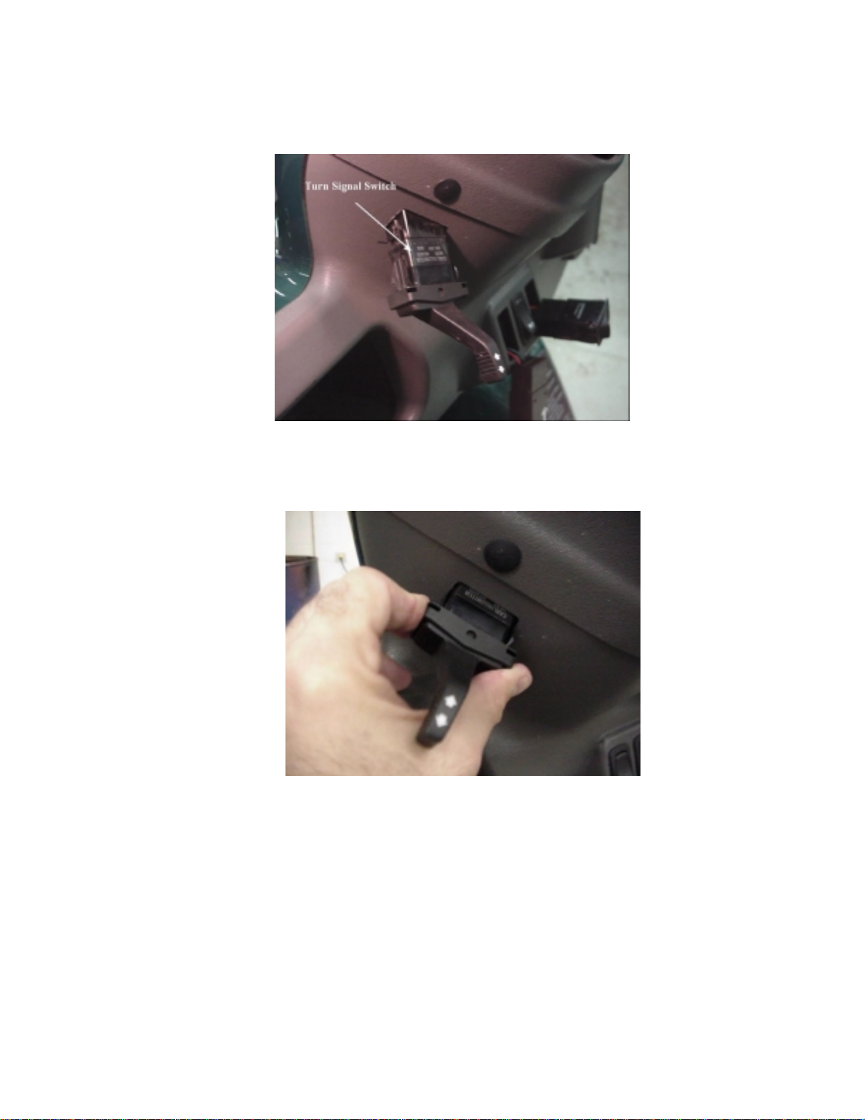
Figure 4-52
Figure 4-53
4-38
Page 55

TURN SIGNAL SWITCH REMOVAL & INSTALLATION
STEP DETAILS
Make sure vehicle safe. Switch off and key removed.
Set parking brake.
Remove switch (Figure 4-52). Use screwdriver to
panel.
Unplug switch.
Install new switch (Figure 4-53). Plug new switch into wiring harness.
Turn switch so it is properly oriented and press
into panel.
Test. Switch on.
Press switch lever up for right turn signal,
down for left.
Tie wrap any excess wire so it is out of the
way.
gently
pry switch out from
4-39
Page 56

Figure 4-54
Figure 4-55
4-40
Page 57

ACCELERATOR POT (THROTTLE SENSOR) REMOVAL
& INSTALLATION
STEP DETAILS
Make sure vehicle is safe. Switch off and key removed.
Set parking brake.
Remove pot (Figure 4-54). Two screws – need 5/16” socket wrench or
common point screwdriver.
Disconnect pot (Figure 4-55). From wiring harness.
Install new pot. Mount with two screws.
Plug into wiring harness.
Make sure any excess wire is tie wrapped out of
the way.
Test new pot. Check vehicle acceleration and speed are
normal.
4-41
Page 58

Figure 4-56
Figure 4-57
4-42
Page 59

INSTRUMENT CLUSTER REMOVAL & INSTALLATION
STEP DETAILS
Make sure vehicle is safe. Switch off and key removed.
Set parking brake.
Pry instrument cluster loose from panel
(Figure 4-56).
Unplug instrument cluster (Figure 4-57). From wiring harness.
Install new instrument cluster. Plug new cluster into wiring harness.
Check instruments. Make sure all instruments operating properly.
Use care to not damage cluster or panel.
Press new cluster into housing.
Turn switch off and remove key.
4-43
Page 60
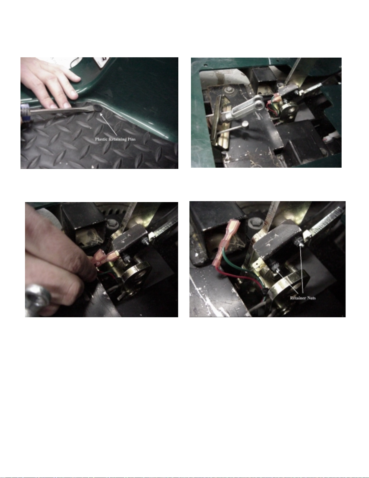
Figure 4-58
Figure 4-59
Figure 4-60
Figure 4-61
4-44
Page 61

PARK BRAKE SWITCH REMOVAL & INST ALLATION
STEP DETAILS
Check machine safe. Switch off and key removed.
Block wheels if necessary.
Remove floor mat and guard plate
(Figure 4-58).
Uncouple brake cable connection
(Figure 4-59).
Disconnect parking brake indicator light
switch wires (Figure 4-60).
Check switch. When brake is fully up, switch should be
Pry plastic retaining pins loose. Be careful to
not tear floor mat.
Guard plate lifts off when floor mat removed.
Remove spring retainer from clevis pin.
Pull clevis pin out and push cables and rod to
rear to allow switch removal.
Pull two connectors from tabs at on parking
brake indicator light switch. Green from top
tab and red from second tab.
closed between common and next contact.
Switch should be open when park ing brak e is
set.
If switch does not show closed when brake is
up check switch activator arm. Try raising it
slightly and see if switch will close. If this
works, bend arm just enough to cause switch
to close when brake is up.
Change switch if necessary (Figure 4-61). Remove retainer nuts, slide switch and switch
guard off and replace.
Note: be careful to not over-tighten nuts.
Connect wiring. Red wire plugs onto second tab and green
wire to top tab.
Connect brake cables. Install clevis on brake lever.
Make sure clevis pin and spring pin are
secure.
Check lights. Make sure parking brake indicator light is
operating properly.
Replace guard plate. So pins in floor mat will hold it in place.
Replace floor mat. Press pins into holes in floor.
4-45
Page 62

Figure 4-62
Figure 4-63
Figure 4-64
Figure 4-65
Figure 4-66
4-46
Page 63

BRAKE LIGHT SWITCH REMOVAL & INSTALLATION
STEP DETAILS
Check machine safe. Switch off and key removed.
Block wheels if necessary.
Remove floor mat and upper guard plate
(Figure 4-62).
Uncouple brake cable connection
(Figure 4-63).
Remove lower guard plate (Figure 4-64). Unscrew two 7/16” hex head bolts and
Disconnect brake light switch wires (Figure 4-
65).
Check switch. When brake is fully up, switch should be
Pry plastic retaining pins loos e.
Guard plate lifts off when floor mat removed.
Remove spring retainer from clevis pin.
Pull clevis pin out and push cables and rod to
rear to allow switch removal.
carefully remove plate.
Green wire from bottom (common) tab and
black wire from next tab up.
closed between common and next contact.
Switch should be open when brak e is
depressed.
If switch does not show closed when brake is
up check switch activator arm. Try raising it
slightly and see if switch will close. If this
works, bend arm just enough to cause switch
to close when brake is up.
Change switch if necessary (Figure 4-66). Remove retainer nuts, slide switch off and
replace.
Note: be careful to not over-tighten nuts.
Connect wiring. Green wire to bottom tab and black wire to
next tab up.
Install lower guard plate. Work plate carefully into position.
Install and tighten two bolts.
4-47
Page 64

4-48
Page 65

Connect brake cables. Install clevis on brake lever.
Make sure clevis pin and spring pin are
secure.
Check lights. Make sure brake light is operating properly.
Replace upper guard plate. So pins in floor mat will hold it in place.
Replace floor mat. Press pins into holes in floor.
4-49
Page 66
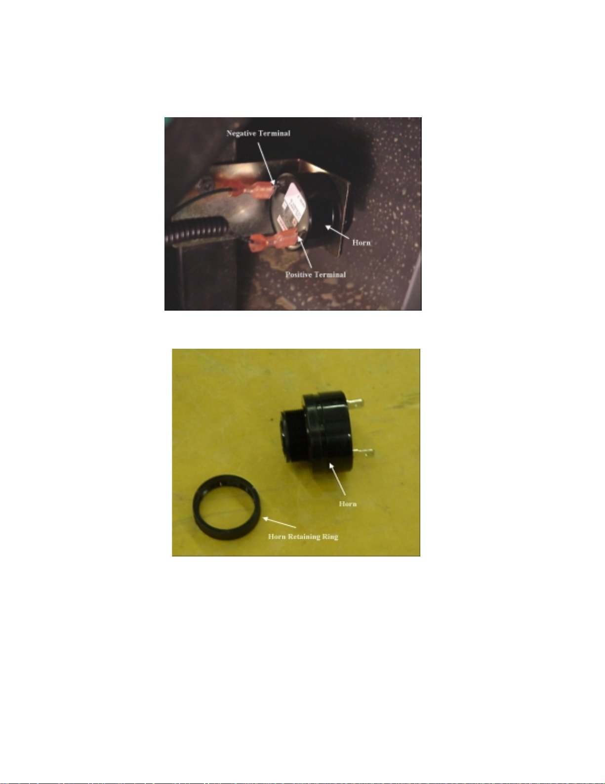
Figure 4-67
Figure 4-68
4-50
Page 67

HORN REMOVAL & INSTALLATION
STEP DETAILS
Make sure vehicle safe. Switch off and key out.
Parking brake set.
Adjust steering. Turn front wheels as far to the right as
possible.
Horn is accessible through right wheel well.
Disconnect horn (Figure 4-67). Remove spade connectors from tabs on horn.
Note that green wire is connected to positive
and black to negative terminals.
Remove horn from bracket (Figure 4-68). Reach between front bumper and horn
mounting bracket and unscrew front of horn
(by hand).
Pull horn out of bracket.
Place new horn in bracket. Insert rear part of horn in bracket and screw
front of horn onto rear. Tighten hand tight.
Connect horn wires. Slide connections onto terminals. Be sure
green wire is connected to positive terminal
and black wire to negative.
Test unit. Switch on and depress horn switch.
4-51
Page 68

4-52
Page 69

SECTION 5: TEST PROCEDURES
Ignition Switch & Jumper Harnes s.......................5-3
Accelerator Pot (Throttle Sensor)........................5-9
Motor.................................................................5-11
Motor Contactor ................................................5-15
Speed Sensor ...................................................5-19
Brake Switch.....................................................5-21
Park Brake Switch.............................................5-23
Directional Signal Switch...................................5-25
Instrument Cluster.............................................5-27
Charger.............................................................5-29
Battery Pack Evaluation....................................5-31
5-1
Page 70

SECTION 5:
Figure 5-1
Figure 5-2
5-2
Page 71

IGNITION SWITCH & JUMPER HARNESS TEST
PROCEDURES
STEP DETAILS
Make vehicle safe. Ignition switch off and key removed.
Parking brake set.
Disconnect jumper harness from main
harness.
Connect ohmmeter leads to pins 3 and 4 of
jumper harness (See Figure 5-1).
Connect ohmmeter leads to pins 2 and 3
(readings same as pins 3 and 4). See Figure
5-1.
Connect ohmmeter leads to pins 2 and 4.
See Figure 5-1
Further action. If any readings are not as shown (or very close),
Connect ohmmeter leads to pins 32 and 33
on large controller connector. See Figure 5-
2.
Reconnect jumper harness to main harness.
Readings should be as shown below when
ignition switch is in position shown:
Reverse………………1 k ohms
Off……………………..open circuit
Hi………………………. 2 k ohms
Lo……………………… 4 k ohms
Readings should be as shown below when hi-lo-
reverse switch is in position shown:
Reverse………………1 k ohms
Off……………………..open circuit
Hi………………………. 2 k ohms
Lo……………………… 4 k ohms
Should show near zero ohms in all switch
positions except “off”. Off position should show
open circuit.
disconnect jumper harness from switch and
check jumper harness and switch individually.
If readings were ok, go to next steps.
Readings should be as shown below when hi-lo-
reverse switch is in position shown:
Reverse………………1 k ohms
Off……………………..open circuit
Hi………………………. 2 k ohms
Lo……………………… 4 k ohms
Connect ohmmeter leads to pins 32 and 31
on large controller connector. See Figure 5-
2.
Connect ohmmeter leads to pins 31 and 33
on large controller connector. See Figure 5-
2.
Replace wiring harness. If any reading taken through main harness shows
Readings should be as shown below when
ignition switch is in position shown:
Reverse………………1 k ohms
Off……………………..open circuit
Hi………………………. 2 k ohms
Lo……………………… 4 k ohms
Should show short circuit in all switch positions
except “off”. Off position should show open
circuit.
different than described.
5-3
Page 72

Figure 5-3
5-4
Page 73

JUMPER HARNESS TESTING PROCEDURES
Step Details
Jumper harness has resistors in the wiring and must be tested separately from the switch when
switch malfunction is suspected. Problem might be in harness and not switch.
An ohmmeter is required.
Make vehicle safe. Switch off and key removed.
Parking brake set.
Remove harness section. Unplug from back of switch.
Disconnect from main harness.
Measure resistances between pins as
shown in Figure 5-3.
If measurements are significantly different
than those shown, the problem is probably in
the jumper harness.
If all measurements are good, check switch.
Measure from pin 4 to pin:
A – open circuit.
B – open circuit
C – 2 k ohms
D – 0 ohms
E – 4 k ohms
F – 1 k ohms
Measure from pin 3 to pin:
A – open circuit
B – 0 ohms
C – open circuit
D – open circuit
E – open circuit
F – open circuit
Measure from pin 2 to pin:
A – 0 ohms
B – open circuit
C – open circuit
D – open circuit
E – open circuit
F – open circuit
Measure from pin 1 to pin:
A – open circuit
B – open circuit
C – 2 k ohms
D – 4 k ohms
E – 0 ohms
F – 3 k ohms
5-5
Page 74

Figure 5-4
5-6
Page 75

IGNITION SWITCH TESTING PROCEDURES
STEP DETAILS
Make vehicle safe. Switch off and key removed.
Parking brake set.
Remove switch. Remove retainer nut and pull switch out from
back of panel.
Unplug jumper harness from switch.
Check switch continuity. See Figure 5-4. Use ohmmeter to check pins as shown on
Figure 5-4. Pins shown should show near zero
ohms when switch is in positions shown below.
Reverse: B to F D to A
Off position: none of the listed pins connected.
High: B to C D to A
Low: B to E D to A
Replace switch. If resistance readings are not correct.
5-7
Page 76

Figure 5-5
Figure 5-6
5-8
Page 77

ACCELERATOR POT (THROTTLE SENSOR) TESTING
PROCEDURES
STEP DETAILS
Make sure vehicle safe. Turn ignition switch off and remove key.
Set parking brake.
Check resistance of pot. See Figure 5-5. Disconnect pot from harness and take
measurements on pot side of connection while
depressing accelerator. Pin numbers are on the
connector.
Pin 1 to pin 3………… 5 k ohms at all times.
Pin 1 to pin 2………… 15 k ohms to 10 k ohms.
Pin 2 to pin 3………… 10 k ohms to 15 k ohms.
Measure continuity. See Figure 5-6. Of combined harness and pot circuit. Plug pot
connector into main harness.
Measure resistance from pin 27 to pin 28 on the
large controller connector. When accelerator is
depressed resistance should go from 15 k ohms
to 10 k ohms.
Measure from pin 28 to pin 29. Resistance
should go from 10 k ohms to 15 k ohms.
Measure from pin 27 to pin 29. Resistance
should stay at 5 k ohms.
If resistances are correct then pot and harness
are ok. If resistances different than those
shown, proceed to next step.
What to do??? If entire harness and pot check good, problem
must be somewhere else.
If pot is good and harness and pot showed bad,
must be fault in harness.
If pot readings not correct, change pot.
5-9
Page 78

Figure 5-7
5-10
Page 79

MOTOR TEST PROCEDURES
STEP DETAILS
Make vehicle safe. Ignition switch off and key removed.
Parking brake set.
Remove utility bed (or storage compartment). Whichever is installed.
Remove 4 screws from utility bed or lift storage
compartment out.
Turn off master power switch. Located behind seat.
Remove canopy assembly. If installed, refer to Section 4.
Remove rear body section. Refer to Section 4.
Disconnect one motor cable. Recommend disconnect motor return cable from
controller.
Raise and support vehicle. Raise rear until wheels are clear.
Place supports under vehicle.
Attach ohmmeter leads. See Figure 5-7. To motor cable terminal ends.
Check resistance in motor.
Note: Check resistance from motor lead
to case on motor to make sure lead is not
grounded
motor housing, replace motor.
High resistance or large changes indicate
problems with brushes or commutator in
motor.
Lower vehicle. Remove supports and lower.
Reconnect motor cable. To original position.
Turn on master power switch. Located behind seat.
If motor lead has continuity to
.
Should be less than one ohm.
Rotate wheels in small increments (stopping to
read resistance) and make sure resistance is
not more than one ohm at any position
Replace motor
.
5-11
Page 80

Figure 5-8
5-12
Page 81

Test motor current draw (Figure 5-8).
Note: Test should be done with driver
only, (no payload) and on level ground.
Install rear body section.
Install canopy.
If motor is weak, performance is bad or is
suspected to cause low range or overheating of
controller.
Connect clamp on inductive current sensor to
one of the motor cables and set meter to read
current of up to 150 amps. Drive vehicle and
record current readings at various speeds as
follows. Drive at a steady speed on level ground.
5mph – 25 to 35 amps
12mph – 30 to 45 amps
Note: Values are approximate and may vary
some with different terrain and driver
weights. If amperage is considerably higher
than it should be, the motor is not operating
efficiently. Make sure there is no mechanical
problem causing motor to overwork, such as
dragging brakes.
Install utility bed or storage compartment.
Note: Storage compartment fits into rear
area with no fasteners.
For utility bed, make sure spacers are positioned
to keep bed from distorting body section when
screws are tightened.
5-13
Page 82

Figure 5-9
Figure 5-10
5-14
Page 83

MOTOR CONTACTOR TEST PROCEDURES
STEP DETAILS
Make vehicle safe. Ignition switch off and key removed.
Parking brake set.
Turn off master power switch. Switch behind seat.
Remove utility bed (or storage compartment). Whichever is installed.
Remove canopy assembly. If installed, refer to Section 4.
Remove rear body section. Refer to Section 4.
Disconnect large controller (positive motor
output) cable from contactor.
Check voltage on contactor activation
terminals (Figure 5-9).
Note: 12 volts is applied to the activation
terminals initially to activate the contactor.
Then voltage is pulsed to hold contactor
closed. The pulsed voltage will read about
5 volts with a digital voltmeter.
Note: If the voltage at the activation
terminals continues to read 12 volts, the
coil circuit of the contactor is most likely
“open.”
Shield terminal end of cable so it cannot touch
you or anything else (cover with tape or other
suitable insulatio n) .
Turn on master power switch.
Turn ignition switch to a run position.
Check voltage on activation terminals. Should
be about 5 volts.
If voltage is present and contactor “clicks”
closed, check resistance between motor and
controller power terminals on contactor.
Should be less than 1 ohm. (See Figure 5-10)
If no voltage present, check continuity of
activation wires to large twist lock connector at
controller.
Orange wire to pin 11
White wire to pin 12
If no continuity, repair or replace harness as
needed.
If continuity is good on both wires, controller
may be bad if no other faults are present.
5-15
Page 84

5-16
Page 85

Replace contactor if necessary. If voltage is present at activator terminals but
does not cause contactor to close.
If contactor closes but more than one ohm of
resistance is present between motor power
terminals.
Reconnect motor power cable. To original position.
Turn on master power switch. Located behind seat.
Check operation. Make sure vehicle operates properly.
Reassemble. Rear body section.
Utility bed or storage container.
Canopy assembly.
5-17
Page 86

blue
blue
Speed
Speed
Sensor
Sensor
Figure 5-11
black
black
brown
brown
1 2 3
1 2 3
Sensor Plug
Sensor Plug
1K
1K
Volts
Volts
Ω
Ω
_
_
Battery
Battery
+
+
5-18
Page 87

SPEED SENSOR TEST PROCEDURES
STEP DETAILS
Remove utility bed. If equipped.
Remove trunk basket. Lifts out.
Test speed sensor using test tool.
Note: This test can be done with a DMM,
but it is more easily done with an analog
voltmeter.
Test speed sensor without test tool.
See Figure 5-11.
Note: This test is only to be used when test
tool is not available.
Jack and support rear of vehicle with tires off
floor. Plug tool to the speed sensor. Connect
voltmeter to tool. Turn switch to “on.”
Slightly move the tire until voltage reads
approximately 9 volts. Slightly move the tire
more until the voltage reads near zero.
If the tire can be moved so that the voltage
reads 9 volts and near zero volts, speed sensor
is operating properly.
Note: If speed sensor is to be tested while
out of the vehicle, connect tool and put a
piece of ferrite metal in front of sensor pick
up and then remove. With metal in place,
the voltage should be near zero, and with
metal removed, voltage should be
approximately 9 volts.
Unplug speed sensor.
Connect a 1K-ohm resistor across pin 2 (black
wire) and pin 3 (brown wire) of sensor plug.
Connect a battery across pin 1 (blue wire) and
pin 3 (brown wire).
(Use a 9 volt transistor battery or a 12 volt
cranking battery)
Measure voltage between pin 1 and pin 2.
Move tire slightly to get a voltage reading that
is approximately equal to the battery voltage.
Then slightly move tire to a point where voltage
is near zero.
If voltage can be changed from the battery
voltage to near zero volts the sensor is good.
5-19
Page 88

Figure 5-12
Figure 5-13
5-20
Page 89

BRAKE SWITCH TEST PROCEDURES
STEP DETAILS
Remove rubber floor mat. Pry out plastic retaining pins.
Remove upper guard plate. Lifts off.
Remove brake pull and lower guard plate. See
Figure 5-12.
Test switch. See Figure 5-13.
Note: Wires should be attached to two
lower spade terminals of switch.
Note: Check switch lever to make sure
brake pedal arm is pushing and releasing
switch lever.
Remove spring clip and clevis pin from brake
pull. Remove two hex head bolts from lower
guard plate. Remove guard plate and remove
brake pull or secure out of way.
With both wires still plugged to switch and key
to an “on” position. Check instrument cluster to
make sure the selected mode and on lights are
illuminated (block wheels or raise rear wheels
off ground to prevent accidental runaway of
vehicle). Touch the voltmeter leads to the
spade terminals just in front of the wire
connectors (polarity not im portant) . Be careful
to touch only the spade terminals with the
voltmeter leads.
Pedal up – should be 0 volts.
Pedal depressed – should be approximately 6
volts (polarity not important).
If both voltages are correct, then the switch and
wiring from controller are good.
If both voltages are approximately 6 volts, then
the switch is bad (open).
Note: There is a connector on the inside of
right frame rail to the right of the brake
pedal in this circuit. If no continuity, check
connector.
If both voltages are zero, then unplug the wires
and check voltage at wires. If voltage of
approximately 6 volts is present, then switch is
bad (shorted).
If no voltage on wires, check continuity of wires
to controller (should be less than 1 ohm).
Black wire to pin 18 of large twist lock
connector.
Green wire to pin 38 of large twist lock
connector.
If either wire does not have continuity to
controller, repair wire or replace harness as
needed and retest.
If both wires have continuity to controller, then
the controller is faulty.
5-21
Page 90

Figure 5-14
5-22
Page 91

PARK BRAKE SWITCH TEST
STEP DETAILS
Remove rubber floor mat. Pry out plastic retaining pins.
Remove upper guard plate. Lifts off.
Test Switch.
Note: Wires should be attached to two
upper terminals of switch.
Note: check switch lever to make sure park
brake mechanism is pushing and releasing
switch lever.
With both wires still plugged to switch and key
to an “on” position, check instrument cluster to
make sure selected mode and on lights are
illuminated (block wheels or raise rear wheels
off ground to prevent accidental runaway of
vehicle). Touch the voltmeter leads to the
spade terminals just in front of the wire
connectors (polarity not im portant) . Be careful
to touch only the spade terminals with the
voltmeter leads. See Figure 5-14.
Pedal up – should be 0 volts.
Pedal set in park position – should be
approximately 6 volts (polarity not important).
If both voltages are correct, then the switch and
wiring from controller are good.
If both voltages are approximately 6 volts, then
the switch is bad (open).
If both voltages are zero, then unplug the wires
and check voltage at wires.
If voltage of approximately 6 volts is present,
then switch is bad (shorted).
If no voltage on wires, check continuity of wires
to controller (should be less than 1 ohm).
Red wire to pin 19 of large twist lock connector.
Green wire to pin 38 of large twist lock
connector.
If either wire does not have continuity to
controller, repair wire or replace harness as
needed and retest.
Note: There is a connector on inside of right
frame rail to right of brake pedal in this
circuit. If no continuity, check connector.
If both wires have continuity to controller, then
the controller is faulty.
5-23
Page 92
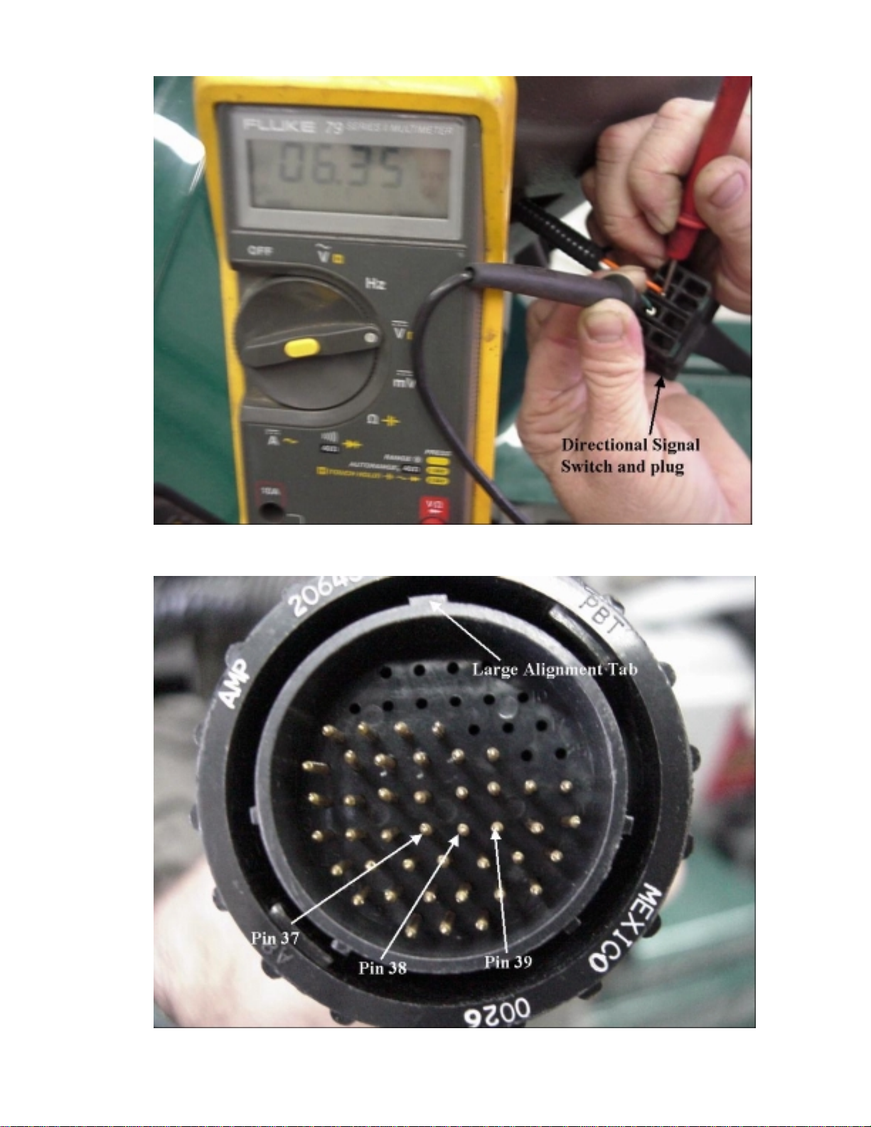
Figure 5-15
Figure 5-16
5-24
Page 93

DIRECTIONAL SIGNAL SWITCH TEST
STEP DETAILS
Remove signal switch. Gently pry switch from dash.
Remove signal switch.
Test switch. See Figure 5-15.
Set parking brake with switch plugg ed in and
key to an on position. Check instrument cluster
to make sure the on light and selected mode
light is illuminated. Check voltage at switch
from orange to green wires. Should be 6 volts
with signal switch off and 0 volts with signal
switch in the right turn position.
Check voltage from white to green wires.
Should be 6 volts with signal switch off and 0
volts with signal switch in the left turn position.
If all voltages check correct, switch and wiring
to controller are good.
If 6 volts present with switch on in either
direction, switch is bad (open).
If voltage is zero or near zero with signa l s witch
in off position, unplug switch and check voltage
at harness connector.
Orange to green should be 6 volts
White to green should be 6 volts
If voltage present on both wires, the switch is
bad (shorted).
Test wires. See Figure 5-16.
If no voltage, check continuity of wires to
controller.
Orange wire to pin 37 of large twist lock
connector.
Green wire to pin 38 of large twist lock
connector.
White wire to pin 39 of large twist lock
connector.
If no continuity on any wire, repair or replace
wire harness as needed and retest.
If continuity on all wires, replace controller.
5-25
Page 94

Figure 5-17
Figure 5-18
5-26
Page 95

INSTRUMENT CLUSTER TEST PROCEDURES
(Nothing on cluster works but rest of vehicle ok)
STEP DETAILS
Remove instrument cluster. Gently and carefully pry cluster from dash.
Unplug connector. From back of cluster.
Check for power to cluster.
Note: Pin locations are numbered on back
of plug.
Check wiring to cluster.
Set park brake. Turn ignition switch to an on
position. Check voltage from red wire (pin 5) to
green wire (pin 12). Should be 12 volts. See
Figure 5-17.
If voltage present, plug connector back into
cluster and use a paper clip or small stiff wire
to jump from pin 23 to pin 12 at back of
connector. Green “on” light should illuminate.
See Figure 5-18.
If illuminates, controller is most likely at fault.
If does not illuminate, replace instrument
cluster.
If no voltage present, check continuity of wires
to controller.
Instrument Cluster Large Twist Lock
Connector Controller Connector
Red wire (pin 5) to pin 50
Green wire (pin 12) to pin 51
If no continuity on either wire, repair or replace
wire harness as needed.
If continuity on both wires, replace controller.
5-27
Page 96

5-28
Page 97

CHARGER TESTING PROCEDURES
It is important for the charger to operate
properly to completely charge the batteries,
have a full range, provide long battery life,
and do it all safely.
The charger must supply current to the
battery pack to recharge it. As the battery
pack accepts more current, the voltage of
the pack will rise. The voltage cannot go
over a set amount without damage to the
battery and possible excessive gassing of
the battery. As the pack voltage approaches
the maximum value, the charger must begin
to reduce the current to maintain the voltage
at the proper level. When only a small
amount of current is needed to hold the pack
voltage at the maximum value, the batteries
are completely charged and the charger will
go into float mode.
In float mode, the charger will maintain the
voltage at a level a little lower than the
maximum charging voltage. Only a small
amount of current is required to float the
batteries.
While in the main charge mode, the red LED
on the charger will be on. During the time
near the end of the main charge and the
beginning of the float charge when the
transition is being made, both the red and
green LED indicators will be on. Onc e the
charger is in float mode and is just
maintaining the charge, only the green LED
indicator will be on.
If it is suspected that the charger is not
operating as it should, it can be tested with
the following procedures:
•
Battery must not be at full charge. It is
not necessary that the battery be
completely discharged, but it should be
partially discharged. The more
discharged, the longer the test will take.
•
Connect the voltmeter to the battery
pack main terminals and observe
voltage reading.
•
Plug charger cord in and check to see if
the charge indicator on the instrument
cluster is on.
•
Observe pack voltage, it should start to
rise within a few seconds of starting the
charge.
•
Observe LED indicators on the charger.
The red indicator should be on.
•
Use a clamp on inductive current
sensor to measure charge current.
See Figure 5-19. Clamp the sensor on
the main negative or main positive
battery cable. The current reading
should be between 1 and 6.1 amps.
(The current will reduce as battery
nears a complete charge)
. Figure 5-19
•
Leave charger on and resume other
work. Periodically check the voltage of
the battery pack and the charger LED
indicators.
•
Voltage should eventually climb to
between 56.4 and 58.8 volts. The
charging current will reduce to around 1
amp at this voltage level. At this point
the main charge is nearing completion.
•
Try to observe the LED indicators when
both are on. Both indicators on signals
the transition period from the main
charge to the float charge.
•
At the end of the main charge the
charger will automatically switch to the
float charge. You should observe that
the pack voltage has reduced to 52-
54.4 volts and the current has reduced
to approximately 0.1 amps. During the
float charge, only the green LED should
be on.
5-29
Page 98

If the charger performed all the steps
required, it is operating normally. If the
charger does not charge according to this
procedure, it may undercharge or
overcharge the battery modules resulting in
short battery life and loss of range.
5-30
Page 99

BATTERY PACK EVALUATION
As batteries age and acquire more cycles on
them, they begin to loose capacity. A cycle
is one complete charge and discharge
event. The battery’s cycle life is the amount
of charge/discharge cycles it can take before
it no longer meets the minimum capacity
requirements.
There are several factors that effect the
cycle life of a battery. One significant factor
is internal corrosion, which is caused by
oxidation and hydrogen reduction.
Operating in high temperatures acce ler at es
the corrosion process. Another significant
factor in cycle life is the depth of discharge.
The deeper the discharge, the more difficult
it becomes to reverse the chemical reaction
during charging. This results in a loss of
active material available for use in the next
cycle. A battery that is discharged half way
on each cycle will last for twice as many
cycles as one that is completely discharged
on each cycle.
As the batteries acquire more and more
cycles, they should loose capacity at
approximately the same rate. When all the
batteries in the pack are very close in
capacity the pack is “balanced” or
“equalized.” Under normal circumstances,
the pack should remain balanced throughout
its cycle life, and at the point it can no longer
meet the capacity requirements, it is
replaced.
Occasionally there is a case where one or
more of the modules in the pack degrade at
a different rate than the others causing an
“unbalanced” battery pack. There are
several factors that can cause this. When a
pack is unbalanced, each charge/discharge
cycle worsens the condition. The result is
that the pack reaches the point of not having
enough capacity prematurely. The pack is
only as good as its weakest module. An
unbalanced pack will accelerate the capacity
loss of the weak module.
To ensure a balanced pack, battery
modules on the FunRunner should be
replaced as a set. Replacing only one or
two modules will lead to further imbalance
problems even if the remaining modules test
ok. The new modules will not be at the
same capacity as the old and the imbalance
will worsen with continued c ycles.
Charging the batteries for long periods of
time occasionally will help to keep the
battery pack balanced.
Since the battery modules are sealed gel
type, specific gravity cannot be checked. A
voltage measurement is the only means of
evaluating each module.
Before connecting the voltmeters for testing
batteries, inspect the pack thoroughly. Look
for loose, corroded, or discolored terminals.
Corrosion on the terminals should be from
none to very minimal on sealed batteries.
Excessive corrosion may be an indication
that the module has lost its seal at some
point. Inspect the case for cracks or
damage. Also look for modules that are
swollen or bulged out on the sides. Faulty
modules will often swell or bulge. The
module cases should all feel about the same
temperature during or after operation. Bad
modules will often feel much hotter than a
good module.
feeling module temperature so as to not
touch any high voltage terminals.
After a thorough inspection, you can test the
pack using voltage measurements. Use the
following procedures to evaluate the battery
pack condition:
Be very careful when
Quick Test
•
Connect a voltmeter across the main
terminals of the battery pack.
•
Voltage should be 49 volts or more.
•
Charge batteries some if voltage is low.
•
Drive vehicle and determine if power
and acceleration seem normal (voltage
must stay above 46 volts during test).
•
If vehicle performance and power seem
normal and no fault indications are
given, then the battery pack has most
likely lost capacity if the range has
diminished.
•
Check charger operation to make sure
batteries are getting a full charge (see
“Testing Charger Operation”). If
5-31
Page 100

charger is operating properly, then the
battery pack capacity is most likely low.
Note: Batteries that have lost
capacity will usually still have the
same power they had previously.
For this reason the range of the
FunRunner will be reduced, but the
performance of the vehicle while
driving after a charge will be normal.
A vehicle that is charged completely
and performs well but has a reduced
range will more then likely have a
reduced capacity battery pack.
Some operators that only drive short
distances between charges will not
notice a loss of capacity until it
reaches a point that it will no longer
cover the needed distance on one
charge.
of each other until the end of charge
where they should all become almost
equal. If new battery modules were
installed, leave charger on over nig ht.
The extended float charge will help
balance the pack.
Full Test
•
Batteries should have 50% or more
charge.
•
Remove rear body panel.
•
Perform visual inspection.
•
Connect a voltmeter to each module.
See Figure 5-20.
•
Drive vehicle until battery state of
charge is at approximately ½ charge.
•
Power test - During a hard pull at wide-
open throttle up a hill if possible for
about 10 seconds, observe the
voltages. All modules should maintain
a minimum of 9 volts.
•
Continue to drive the vehicle until the
state of charge gauge drops to ¼
charge.
•
Capacity test – Drive steady at a
moderate speed for about 30 seconds
while monitoring the module voltages.
All module voltages should remain
within 0.5 volts of each other.
•
Replace all modules if any failed the
power or capacity test. If all modules
have tested ok, the pack is balanced
and need not be replaced unless the
pack capacity will not deliver a suitable
range.
•
Leave voltmeters connected and plug
charger cord in to charge the batteries.
•
Monitor the module voltages at various
times during charging. Keep in mind
that a charge will last 7-8 hours.
Voltages should remain with in 0.5 vo lts
Figure 5-20
5-32
 Loading...