

Crown IQPIPUSP-2-CN Owners manual
-PIP-USP2/CN
An IQ System® Programmable Input Processor with
CobraNet™ and DSP for Crown® PIP2-Compatible Amplifiers
© 2001 by Crown Audio, Inc., P.O. Box 1000, Elkhart, IN 46515-1000 U.S.A.
Telephone: 219-294-8000. Fax: 219-294-8329.
Crown Audio, Inc. Trademark Notice:
trademarks, and
registered trademarks of Crown International, Inc. Other trademarks are the
property of their respective owners.
Com-Tech®, Crown
IQ2™, SmartAmp™, PIP
®,
IOC
®
PIP
modules are produced by
,
IQ System
™, and
®
and
PIP2™
ODEP
®
are
are
Obtaining Other Language Versions:
To obtain information in another language about the use of this product, please
contact your local Crown Distributor. If you need assistance locating your local
distributor, please contact Crown at 219-294-8200.
Note: The information provided in this manual was
deemed accurate as of the publication date. However, updates to this information may have occurred.
To obtain the latest version of this manual, please
visit the Crown website at www.crownaudio.com.
Printed on
recycled paper.
132404-1
4/01

IQ-PIP-USP2/CN
The information furnished in this manual does not include all of the details
of design, production, or variations of the equipment. Nor does it cover
every possible situation which may arise during installation, operation or
maintenance. If you need special assistance beyond the scope of this
manual, please contact our Technical Support Group.
Crown Audio Technical Support Group
Plant 2 SW, 1718 W. Mishawaka Rd., Elkhart, Indiana 46517 U.S.A.
Phone: 800-342-6939 (North America, Puerto Rico and Virgin Islands)
Fax: 219-294-8301 Internet: http://www.crownaudio.com
or 219-294-8200
WARNING
Page 2
TO REDUCE THE RISK OF ELECTRIC
SHOCK, DO NOT EXPOSE THIS
EQUIPMENT TO RAIN OR MOISTURE!
IQ-PIP-USP2/CN Reference Manual

IQ-PIP-USP2/CN
FCC COMPLIANCE NOTICE
This equipment has been tested and found to comply with the limits for a Class
B digital device, pursuant to Part 15 of the FCC rules. These limits are designed
to provide reasonable protection against harmful interference in a residential
installation. This equipment generates, uses and can radiate radio frequency
energy and, if not installed and used in accordance with the instruction manual,
may cause harmful interference to radio communications. However, there is no
guarantee that interference will not occur in a particular installation. If this
equipment does cause harmful interference to radio or television reception,
which can be determined by turning the equipment off and on, the user is
encouraged to try to correct the interference by one of more of the following
measures:
• Reorient or relocate the receiving antenna.
• Increase the separation between the equipment and
receiver.
• Connect the equipment into an outlet on a circuit different
from that to which the receiver is connected.
• Consult the dealer or an experienced radio/TV technician
for help.
The user is cautioned that any changes or modifications not expressly
approved by the party responsible for compliance could void the user’s
authority to operate the equipment.
Note: Fast-Ethernet equipment typically complies only with Class-A specifications and, therefore, the supplied EMI suppression cores may be required on
the Primary and Secondary network connections for system compliance.
IQ-PIP-USP2/CN Reference Manual
Page 3

DECLARATION of CONFORMITY
Crown Audio, Inc.
1718 W. Mishawaka Road
Elkhart, Indiana 46517 U.S.A.
European Representative’s Name and Address:
Peter Christensen, Nilesco Europe
Willem Pyerstraat 21
1077 XK Amsterdam, Netherlands
Equipment Type: Control System Components
Family Name: IQ
Model Name: IQ-PIP-USP2/CN
EMC Standards: EN 55103-1:1995 Electromagnetic Compatibility – Product Family
Safety Standard: EN 60065: 1998 Safety Requirements – Audio Video and Similar
I certify that the product identified above conforms to the requirements of the EMC Council
Directive 89/336/EEC as amended by 92/31/EEC, and the Low Voltage Directive 73/23/EES as
amended by 93/68/EEC.
Standard for Audio, Video, Audio-Visual and Entertainment Lighting
Control Apparatus for Professional Use, Part 1: Emissions
EN 55103-1:1995 Magnetic Field Emissions-Annex A @ 10 cm and 1 M
EN 61000-3-3:1995 Limitation of Voltage Fluctuations and Flicker in
Low-Voltage Supply Systems Rated Current ≤16A
EN 55022:1992 + A1:1995 & A2:1997 Limits and Methods of Measurement of Radio Disturbance Characteristics of ITE: Radiated, Class B
Limits; Conducted, Class A
EN 55103-2:1996 Electromagnetic Compatibility – Product Family
Standard for Audio, Video, Audio-Visual and Entertainment Lighting
Control Apparatus for Professional Use, Part 2: Immunity
EN 61000-4-2:1995 Electrostatic Discharge Immunity (Environment E2Criteria B, 4k V Contact, 8k V Air Discharge)
EN 61000-4-3:1996 Radiated, Radio-Frequency, ElectromagneticImmunity (Environment E2, criteria A)
EN 61000-4-4:1995 Electrical Fast Transient/Burst Immunity (Criteria B)
EN 61000-4-5:1995 Surge Immunity (Criteria B)
EN 61000-4-6:1996 Immunity to Conducted Disturbances Induced by
Radio-Frequency Fields (Criteria A)
EN 61000-4-11:1994 Voltage Dips, Short Interruptions and Voltage
Variation
Electronic Apparatus
Signed Date of Issue: March 15, 2001
Larry Coburn
Title
Senior Vice President of Manufacturing

IQ-PIP-USP2/CN
Quick Install Procedure
This procedure is provided for those who are already familiar with IQ System and
CobraNetTM technologies, and who would like to install the IQ-PIP-USP2/CN in the
shortest time possible. Less experienced installers or those wishing a full
explanation of the installation procedure are encouraged to refer to Section 3 where
the full installation procedure is described.
Prepare the IQ-PIP-USP2/CN:
1. Set the IQ address switch S1 (see Figures 2.1 and 3.1) on the IQ-PIP-USP2/CN
to an unused IQ address. (Tip: Record the IQ address on the small field labeled “IQ ADDRESS” that is provided on the PIP panel.)
Prepare the amplifier:
3. Turn down the level controls of the amplifier and turn off the amplifier.
4. Unplug the power cord of the amplifier from the AC mains.
5. Remove the existing PIP or cover panel from the amplifier back panel (two
screws).
Install the IQ-PIP-USP2/CN
6. Carefully ground yourself to the chassis of the amplifier before installing the
IQ-PIP-USP2/CN. It is a good idea to maintain ground contact between yourself and the amplifier while inserting the module into the amplifier in the next
step.
7. Turn the PIP upside down so you can clearly see the two ribbon cable connectors located on the underside of the board near the back corner (see Figure 2.1). Attach the ribbon cables from your amp to the ribbon-cable
connectors. The 20-pin cable should be connected first, then the 18-pin cable
should be connected. Both ribbon cables should run untwisted from the amplifier to the PIP module.
Important:
the cable is properly seated before applying pressure to the connector. Forcing the cable onto the connector could cause the keying tabs, which ensure
proper pin alignment, to break. Connecting the ribbon cables with improper
pin alignments may result in damage to the PIP.
When both cables are firmly attached, turn the IQ-PIP-USP2/CN
upright position and insert into the PIP opening in the back of the amplifier.
Take care while inserting the PIP
stretch the ribbon cables.
8. Tighten the two PIP mounting screws until it is secured to the amplifier back
panel, making sure the supplied star-washers penetrate the powder-coat finish of the PIP panel for good ground connection.
Install the wiring:
9. Connect the IQ-PIP-USP2/CN
if more information is needed).
10. Connect the IQ-PIP-USP2/CN to the CobraNet network hub or switch. Install
the supplied ferrite cores on the network cable, making two turns. (see Section 3.4 if more information is needed).
11. Reconnect the amplifier to the AC mains.
Be careful when attaching the ribbon cable to the connector that
into the amplifier:
to make sure you do not crimp, pinch or
to the IQ System via the IQ Bus (see Section 3.4
back to an
IQ-PIP-USP2/CN Reference Manual
Page 5

CONTENTS
IQ-PIP-USP2/CN
1Welcome8
1.1 Unpacking ..................................... 9
2 Controls, Connectors
& Indicators ........................ 10
3 Installation ......................... 11
3.1 Prepare the PIP ............................ 11
3.2 Prepare the Amplifier ................... 12
3.3 Install the PIP into the Amplifier . 12
3.4 Install the Wiring ......................... 13
3.5 Adjust System Levels .................. 16
4 Hardware Features ................ 17
4.1 IQ Address Switch (S1) ............... 17
4.2 Reset/Preset Switch ..................... 17
4.3 Data Indicator ............................. 18
4.4 Preset Indicator ........................... 18
4.5 CobraNet Indicators ..................... 18
4.6 IQ Bus Input Connector ............... 18
4.7 IQ Bus Output Connector ............. 18
4.8 Primary Network Connector ......... 18
4.9 Secondary Network Connector .... 18
4.10 AUX Input/Output Connector ....... 19
4.11 IQ Bus Drop Out Relay ................ 19
5.8 Amp Output Mode ....................... 21
5.9 Error Reporting ............................ 21
6 CobraNet ............................ 23
6.1 CobraNet Module Parameters ...... 23
6.2 CobraNet Input Routing ............... 24
6.3 CobraNet Output Routing ............ 24
7 Signal Processing ................. 26
7.1 Signal Processing Forms ............. 26
7.2 Signal Routing ............................. 26
7.3 Input Signal Attenuator ................ 26
7.4 Auto Standby ............................... 27
7.5 Input Signal Compressor/Limiter . 27
7.6 Programmable Filters .................. 27
7.7 Signal Delay ................................. 30
7.8 Peak Voltage Limiter .................... 30
7.9 Average Power Limiter ................. 31
7.10 Clip Eliminator ............................. 31
7.11 Thermal Limiter ........................... 31
7.12 Signal Mute ................................. 31
7.13 Output Trim Controls ................... 32
7.14 Polarity Inverter ........................... 32
7.15 Tie Switch .................................... 32
7.16 “Ghost Faders” ............................ 32
5 Amplifier Control
and Monitoring .................... 20
5.1 IOC Event Monitor ....................... 20
5.2 Input Signal Level Monitor ........... 20
5.3 Output Signal Level Monitor ........ 20
5.4 Thermal Headroom Level Monitor 20
5.5 Power/Standby Control ................ 21
5.6 Amp Information ......................... 21
5.7 Amp Mode ................................... 21
Page 6
8 Load Supervision ................. 33
8.1 On/Off .......................................... 33
8.2 High Limit .................................... 33
8.3 Low Limit .................................... 33
8.4 Nominal Load Impedance ............ 33
8.5 Calculate ...................................... 33
8.6 Include in Standard Error Reporting . 33
8.7 Report to AUX ............................. 33
IQ-PIP-USP2/CN Reference Manual

IQ-PIP-USP2/CN
8.8 Test Indicator ............................... 33
8.9 Low/Normal/High Indicator ......... 33
8.10 Z Avg Monitor .............................. 33
9 Utilities ............................. 34
9.1 User Presets ................................ 34
9.2 Memory Backup .......................... 34
9.3 AUX Output .................................. 34
9.4 AUX Input .................................... 34
10 Working With IQ ................... 36
10.1 A Closer Look at IQ ...................... 36
10.2 IQ-PIP-USP2/CN User Interface ... 38
10.3 IQ Bus Wiring .............................. 46
10.4 A Closer Look at CobraNet ........... 47
ILLUSTRATIONS
1.1 IQ-PIP-USP2/CN Front Panel ......... 8
2.1 IQ-PIP-USP2/CN Controls,
Connectors and Indicators .......... 10
3.1 Address Switch (S1) ................... 11
3.2 Installing the IQ-PIP-USP2/CN .... 12
3.3 Standard IQ Bus Wiring “Loops” 13
3.4 RJ-45 Mating Plug ...................... 14
3.5 RJ-45 Output to Barrier Block Input . 14
3.6 RJ-45 Output to Din input. ......... 14
3.7 RJ-45 Input to Barrier
Block Output. ............................... 15
3.8 RJ-45 Input to Din Output. ......... 15
3.9 RJ-45 Output to RJ-45 Input. ..... 15
3.10Network Cable with Installed Core 16
4.1 Indicators .................................... 18
9.1 Aux Input Modes ......................... 34
10.1 Basic Control Panels ................... 38
10.2 General Control Tab .................... 39
10.3 Presets Control Tab..................... 40
10.5 Using the AUX Connector ............ 50
10.6 Load Supervision Applications .... 52
10.7 Q-Factor Calculation .................... 54
10.8 Working with RJ-11 and RJ-45
Connectors .................................. 55
10.9 IQ Address Tables ........................ 55
10.10 Signal Flow Block Diagram ......... 59
11 Specifications ..................... 60
11.1 General ........................................ 60
11.2 IQ Bus Data Communication ........ 60
11.3 Audio ........................................... 61
11.4 IQ System Data Acquisition ......... 61
12 Factory Service .................... 62
10.4 Error Reporting Control Tab ........ 41
10.5 Load Supervision Control Tab..... 42
10.6 Signal Path Control Tab .............. 43
10.7 CobraNet Setup Control Tab ....... 44
10.8 CobraNet Input Control Tab ........ 45
10.9 CobraNet Output Control Tab ...... 45
10.10 Star Network Topology .............. 47
10.11 Multi-Star Topology ................... 48
10.12 The Internal AUX Circuit ............ 51
10.13 A Sample AUX Output Circuit .... 52
10.14 Q-factor vs.Bandwidth ............... 54
10.15 RJ-11 & RJ-45 Pin Assignments .... 55
10.16 IQ Address Switch (S1) Settings
from 0 through 83 ...................... 56
10.17 IQ Address Switch (S1) Settings
from 84 through 167 .................. 57
10.18 IQ Address Switch (S1) Settings
from 168 through 250 ................ 58
10.19 IQ-PIP-USP2/CN Signal Flow
Block Diagram ............................. 59
IQ-PIP-USP2/CN Reference Manual
Page 7
Figure 1.1 IQ-PIP-USP2/CN Front Panel
1 Welcome
The
IQ-PIP-USP2/CN
grammable Input Processor) input
module for
Crown
ible amplifiers.* It connects the amplifier to the IQ Bus of an
®
,
allowing the amplifier to be
tem
controlled and monitored via IQ, and
features
CobraNet
digital audio networking.
The IQ-PIP-USP2/CN
series component. This means it supports IQ UCODE protocol and requires an IQ System with an IQ2compatible IQ interface. UCODE
(universal code) enables users and
third parties to develop custom software objects to control and monitor
IQ2-compatible components like the
IQ-PIP-USP2/CN.
The IQ-PIP-USP2/CN utilizes the latest advancements in DSP technology to provide state-of-the-art features and performance. Similar to
the the IQ-PIP-USP2, it offers a variety of programmable functions in-
* You must have a PIP2-compatible
amplifier to use the IQ-PIP-USP2/CN.
To determine if your amplifier is
PIP2-compatible, look for the
logo on the back of the amplifier. The
IQ-PIP-USP2/CN is NOT compatible
with older Crown PIP amplifiers.
is a
PIP
™ (Pro-
®
PIP2
™-compat-
IQ Sys-
™ connectivity for
is an
IQ2
™-
IQ-PIP-USP2/CN
cluding crossovers, equalizers, signal delay, input compressors, multimode (peak, average, clip) output
limiters and load supervision. The
familiar IQ-AUX port has been enhanced and the “Listen-Bus” feature is now available via CobraNet.
A full 24-bit signal path is maintained by using state-of-the-art 24bit Digital-to-Analog Converters,
along with the audio-industry standard Motorola 56000 series 24/48bit DSP.
The IQ-PIP-USP2/CN is powered by
the amplifier, and all unit parameters are stored in non-volatile Flash
memory for reliable system backup. Ten presets are available for
quick and easy unit configuration
changes. Each IQ-PIP-USP2/CN includes an IQ address switch allowing the unit to have a unique address on the IQ Bus.
This manual will help you successfully install your unit. We strongly
recommend you read all the instructions, warnings and cautions contained within. Also, for your protection, please send in the warranty
registration card today and save
the bill of sale since it is your official
proof of purchase.
Page 8
IQ-PIP-USP2/CN Reference Manual
IQ-PIP-USP2/CN
1.1 Unpacking
The unit is shipped in a protective
antistatic bag.
CAUTION: STATIC ELECTRICITY
MAY DAMAGE THE UNIT. Use cau-
tion when handling the unit. Carefully ground yourself
ing the unit. Avoid unnecessarily
touching the components or solder
pads on the circuit boards.
Please unpack and inspect the unit
for any damage that may have oc-
BEFORE touch-
curred during transit. If damage is
found, notify the transportation company immediately. Only you, the
consignee, may initiate a claim with
the carrier for shipping damage.
Crown will be happy to cooperate
fully as needed. Save the shipping
carton as evidence of damage for
the shipper’s inspection.
Even if the unit arrived in perfect
condition, as most do, save all packing materials. NEVER SHIP THE
UNIT WITHOUT THE FACTORY
PACK.
IQ-PIP-USP2/CN Reference Manual
Page 9
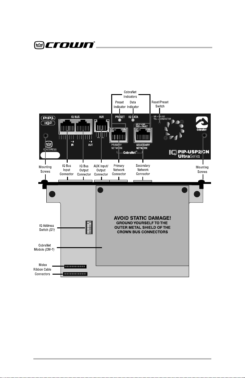
2 Controls, Connectors & Indicators
IQ-PIP-USP2/CN
Figure 2.1 IQ-PIP-USP2/CN Controls, Connectors and Indicators
Page 10
IQ-PIP-USP2/CN Reference Manual

IQ-PIP-USP2/CN
3 Installation
Before beginning, please carefully
note:
CAUTION: STATIC ELECTRICITY
MAY DAMAGE THE IQ-PIP-USP2/CN
MODULE. Use caution when han-
dling the unit. Carefully ground yourself
BEFORE touching the IQ-PIPUSP2/CN module. Avoid unnecessarily touching the components or
solder pads on the circuit boards.
3.1 Prepare the PIP
1. Set the IQ address switch S1
giving each IQ component a
unique address, it can be
individually controlled and
monitored. Whenever the IQ
System wants to send a command
to just one IQ component, it first
sends its address and then the
command down the IQ Bus.
S1 has eight segments because it
actually contains eight tiny
switches inside. The word “ON” is
printed on the switch along its
upper left side to indicate the ON
position and the switches are
numbered along the bottom
(Figure 3.1).
Each of the eight switches in S1
has a value which doubles as the
..
. By
..
switch number increases. For
example switch 1 has a value of 1;
switch 2 has a value of 2; switch 3
has a value of 4; switch 4 has a
value of 8 and so on.
The address is determined by
adding the values of all “ON”
switches. In Figure 3.1, switches
1, 3, 4 and 7 are on. Simply add the
values to find the address:
1+4+8+64=77.
A convenient series of IQ address
tables are included in Section
10.9. The tables show the switch
settings for all 250 addresses.
No two IQ components of the
same type which are connected to
same IQ Bus can have the
the
same address.* Suppose, for
example, an IQ System has two IQ
Bus loops, 1 and 2, and this IQPIP-USP2/CN is to be installed into
loop 1 and given an address of 77.
No other IQ
same address in loop 1. However,
an IQ
same address.
Different IQ components in the
same IQ Bus loop can have the
same address. For example, both
an IQ–USM 810 mixer/processor
and an IQ-PIP-USP2/CN can use
address 77 in the same loop.
A valid IQ address is any number
from 1 to 250. Do not use a number
higher than 250 since they are
PIPs can be given the
PIP in loop 2 can have the
Figure 3.1 Address Switch (S1)
IQ-PIP-USP2/CN Reference Manual
* Note: All IQ PIP modules (
DSP, IQ-P.I.P.-SMT, IQ-PIP-USP2,
are considered the same type, and so
may not share the same address on
the same IQ Bus.
IQ-P.I.P.-
Page 11
etc.)
reserved for special use. An
address of “0” (zero) places the
unit in “stand alone” mode. This
special mode disables the IQ bus
port, preventing communication
with the IQ System.
3.2 Prepare the Amplifier
3. Turn down the level controls (full
counterclockwise) and turn off
the amplifier.
4. Disconnect the amplifier’s
power cord.
5. Remove the existing
the amplifier back panel (two
screws). This may involve
disconnecting the
input adapter. If a PIP2 input
adapter is already present,
remove the ribbon cables from the
adapter.
PIP from
PIP from a PIP2
IQ-PIP-USP2/CN
3.3 Install the PIP into
the Amplifier
6. Carefully ground yourself to the
chassis of the amplifier before
installing the IQ-PIP-USP2/CN. It is
a good idea to maintain ground
contact between yourself and the
amplifier while inserting the
module into the amplifier.
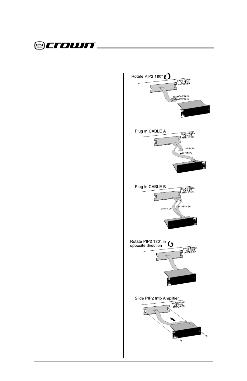
7. Install the IQ-PIP-USP2/CN into
the amplifier: Turn the IQ-PIP-
USP2/CN over so that you can
clearly see the two ribbon-cable
connectors located on the
underside of the circuit board (see
Figure 3.2). Connect the two input
ribbon cables of the amplifier. The
20-pin cable (A) should be
connected first, then the 18-pin
cable (B) should be connected.
Page 12
Figure 3.2 Installing the
IQ-PIP-USP2/CN
IQ-PIP-USP2/CN Reference Manual
IQ-PIP-USP2/CN
Both ribbon cables should run
smoothly from the amplifier to the
PIP card (see Figure 3.2).
Important: Be careful when
attaching the ribbon cable to the
connector that the cable is
properly seated before applying
pressure to the connector.
Forcing the cable onto the
connector could cause the keying
tabs, which ensure proper pin
alignment, to break. Connecting
the ribbon cables with improper
pin alignments may result in
damage to the
When both cables are firmly
attached, turn the IQ-PIP-USP2/
CN back to an upright position and
insert into the
back of the amplifier. Take care
while inserting the
sure you do not crimp, pinch or
stretch the ribbon cables.
8. Tighten the two PIP mounting
screws
the amplifier back panel. Be sure
to use the supplied starwashers for good ground
connection.
PIP.
PIP opening in the
until the
PIP is secured to
PIP to make
There are three different types of
connectors used for IQ Bus wiring
on IQ components. These include
DIN connectors, screw terminal
plugs, and RJ-45 connectors. The
IQ-PIP-USP2/CN uses RJ-45
connectors that accept standard
RJ-45 plugs like the one shown in
Figure 3.4, allowing the use of
industry-standard straight-thru
type network cables. The left RJ45 connector is used for input and
the right RJ-45 connector is used
for output.
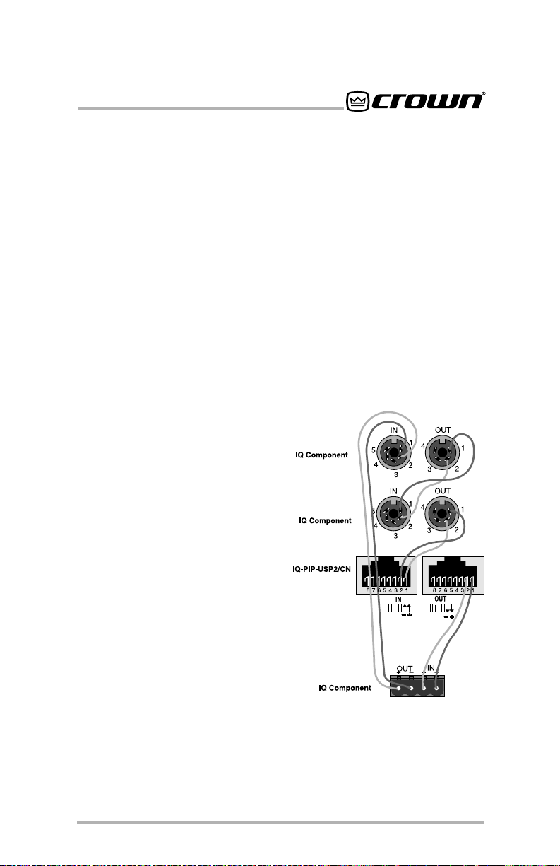
3.4 Install the Wiring
9. Connect the IQ-PIP-USP2/CN to
the IQ system via the IQ Bus. The
IQ components in a IQ Bus loop
are wired sequentially. The loop
begins and ends with the IQ
interface. The output of one IQ
component “loops” to the input of
the next and so on as shown in
Figure 3.3.
IQ-PIP-USP2/CN Reference Manual
Figure 3.3 Standard IQ Bus Wiring
“Loops” from the Output to the Input
of each IQ Component.
Page 13
IQ-PIP-USP2/CN
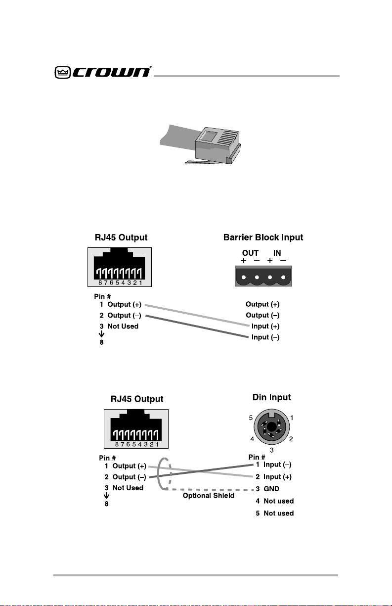
Figure 3.4 RJ-45 Mating Plug
The following examples show how to connect the IQ-PIP-USP2/CN to other
IQ components:
Page 14
Figure 3.5 RJ-45 Output to Barrier Block Input.
Figure 3.6 RJ-45 Output to Din Input.
IQ-PIP-USP2/CN Reference Manual
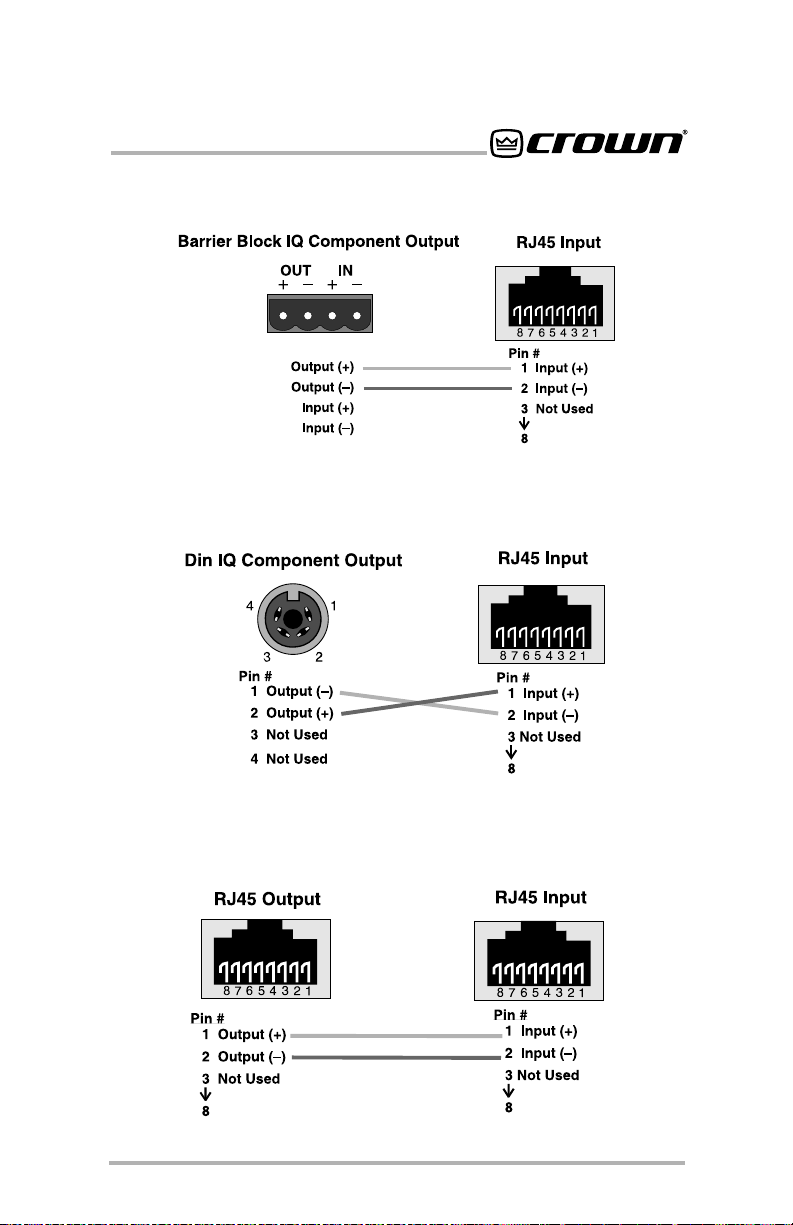
IQ-PIP-USP2/CN
Figure 3.7 RJ-45 Input to Barrier Block Output.
Figure 3.8 RJ-45 Input to Din Output.
Figure 3.9 RJ-45 Output to RJ-45 Input.
IQ-PIP-USP2/CN Reference Manual
Page 15

IQ-PIP-USP2/CN
10. Connect the CobraNet network
to the IQ-PIP-USP2/CN. Connect
the primary network hub or switch
to the primary network port on the
PIP using high-grade UTP Cat-5
and “best” wiring practices for
best results. For compliance with
emission regulations, one of the
supplied ferrite cores must be
placed on the cable, with the cable
making two passes through the
core (see Figure 3.10).* Good
network design and wiring
practices are essential for reliable
system operation.
11. Connect the secondary network
port to the secondary “backup”
network hub or switch if desired.
For compliance with emission
regulations, one of the supplied
ferrite cores must be placed on the
cable, with the cable making two
passes through the core (see
Figure 3.10).* The IQ-PIP-USP2/
CN will automatically “switchover” to this backup connection if
the primary network connection
fails.
12. Reconnect amplifier to the AC
receptacle.
3.5 Adjust System Levels
13. Adjust attenuator levels both on
the amplifier and on the IQ-PIPUSP2/CN control panels within
your IQ software for optimum
system gain.
Figure 3.10 Network Cable with Installed Core
* To minimize the possiblility of a cable
conductor being broken as a result of
installing the ferrite core, use stranded
Cat-5 cable, which is flexible and unlikely to break under this condition.
Page 16
IQ-PIP-USP2/CN Reference Manual

IQ-PIP-USP2/CN
4 Hardware Features
This section describes the IQ-PIPUSP2/CN hardware features. These
features are accessed via controls
located on the unit itself.
4.1 IQ Address Switch (S1)
An 8-section DIP switch is used to
set the IQ address of the unit. A valid
IQ address is any number from 1 to
250. Numbers higher than 250 are
reserved for special use. An address of “0” places the unit in standalone mode. In this mode, the IQ
bus port is disabled and the
not function with IQ software.
This switch is located on the underside of the circuit board. Each IQ
component on a IQ Bus is given a
unique IQ address so it can be independently controlled and monitored.
Two or more IQ components of the
same type should NEVER have the
same address on the same IQ Bus
loop.
For information on setting the IQ
Address Switch, see Section 3.1.
4.2 Reset/Preset Switch
A recessed reset/preset switch, accessible from outside the
performs two functions. First, it enables the IQ-PIP-USP2/CN to be
restored to factory default settings,
and second, allows the user to recall any of ten presets.* A straightened paper clip or similar small object is required to press the reset
switch.
* Max Preset and Min Preset objects dic-
tate the range of Presets that can be
selected by the Reset/Preset Switch.
PIP will
PIP panel,
To select one of the ten presets,
complete the following steps:
Remove all input signals. With the
power on, briefly press the switch
for less than two seconds to toggle
through the 10 user-defined presets
stored in firmware. Each press will
increment the selected preset by
one. After the switch is released, the
DATA light will flash rapidly for a
moment, then the PRESET indicator
will blink to indicate the preset number selected. Restore input signals.
To restore the unit to the factory
default settings, complete the following steps:
Remove all input signals. With the
power on, press the switch and hold
for more than 2 seconds, or until the
DATA indicator blinks twice, and all
settings will be reset to factory default. When the switch is released,
the DATA indicator will flash rapidly
for a moment. Restore input signals.
To clear all memory and set to
factory default presets:
Remove all input signals. Press in
and hold the switch
power to the unit. The settings will
be reset to factory default. Impor-
tant: This action will re-write the
flash memory and erase stored
presets. With the button held in and
power applied, the DATA and PRESET indicators will both be lit. When
the button is released, then the DATA
indicator will flash rapidly for a moment. After the unit has been reset to
the factory default settings, it will
behave like a standard
reprogrammed by an IQ System. Restore input signals.
while applying
PIP until it is
IQ-PIP-USP2/CN Reference Manual
Page 17
IQ-PIP-USP2/CN
4.3 Data Indicator
An amber Data Indicator (IQ DATA)
is provided on the front panel (see
Figure 4.1). It flashes whenever commands addressed to the IQ-PIPUSP2/CN are received. To assist
with troubleshooting, an option that
forces the DATA indicator to remain
lit is available through IQ software.
4.4 Preset Indicator
A green PRESET indicator is provided on the front panel (see Figure
4.1). This indicator signals the number of the currently selected preset
by emitting a series of flashes which
match the preset number, followed
by a pause. The indicator will continuously repeat the number selected
until a change is made to any setting.
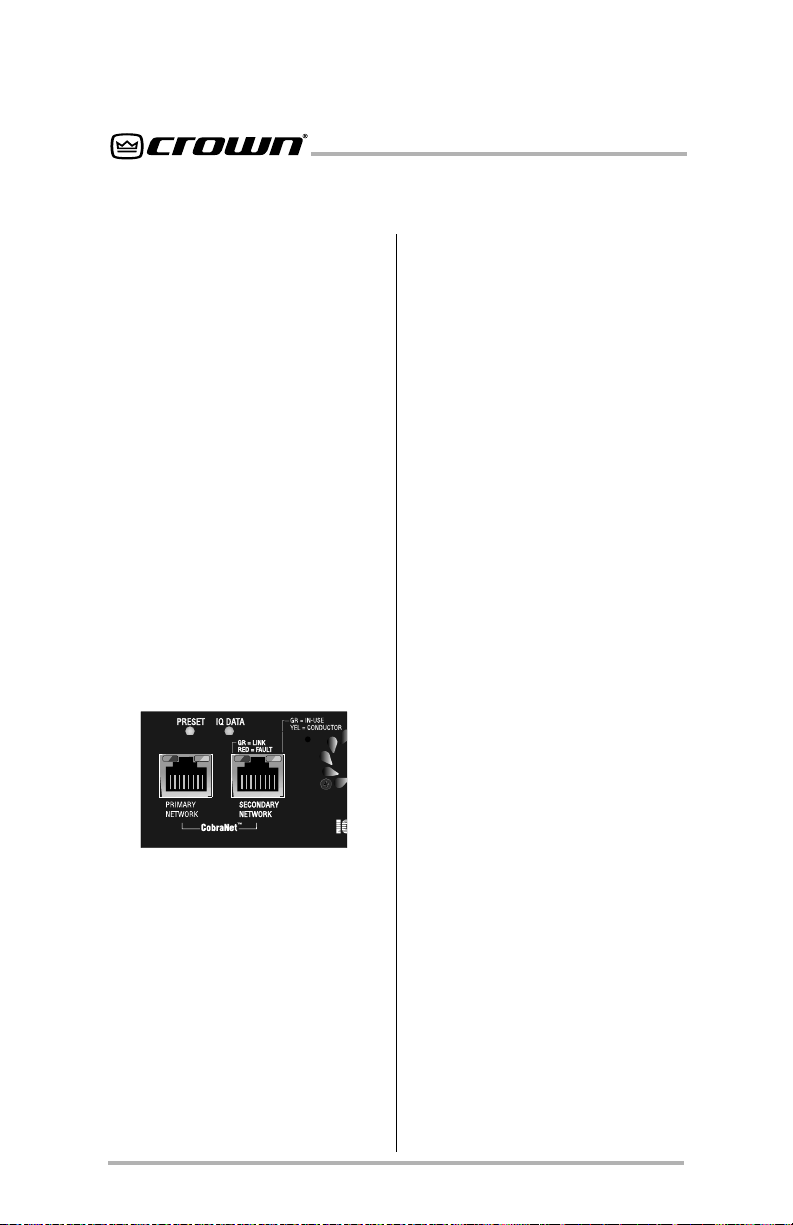
Figure 4.1 Indicators
4.5 CobraNet Indicators
Each CobraNet RJ-45 connector has
two indicators to show network status (See Figure 4.1).
The indicator on the left side of each
RJ-45 connector is dual-color. It
flashes Green if the network link is
connected and operating normally,
and turns ON Red to indicate detection of an unexpected condition
within the CobraNet interface (Fault)
The indicator on the right side of
each RJ-45 connector is also dualcolor. It turns ON Green if the port is
“in-use” (i.e. the link is being used to
transmit or receive active CobraNet
channels), and turns ON Orange if
the port is operating as the network
“Conductor” (Conductor Mode is
described in section 6.1.1.)
4.6 IQ Bus Input Connector
An RJ-45 connector provides input
connection to the IQ Bus. A drop-out
relay maintains loop integrity in the
event power is removed from the IQPIP-USP2/CN.
4.7 IQ Bus Output
Connector
An RJ-45 connector is provided for
wiring output to the next device on
the loop in the IQ Bus.
4.8 Primary Network
Connector
This connector is the main connection to a CobraNet network. The port
is implemented as a standard
100Base-T Fast-Ethernet interface
and should be wired with standard
UTP Cat-5 or better cabling.
4.9 Secondary Network
Connector
This connector is the “backup” or
redundant connection to the
CobraNet network. If the Primary
connection fails due to cut-wire,
failed network switch, etc., this port
is automatically enabled and ready
to receive the network data within a
Page 18
IQ-PIP-USP2/CN Reference Manual

IQ-PIP-USP2/CN
few seconds. The port is implemented as a standard 100Base-T
Fast-Ethernet interface and should
be wired with standard UTP Cat-5 or
better cabling.
4.10 AUX Input/Output
Connector
An RJ-11 connector provides both
Auxiliary input and output connection to outside circuits. Operation of
the AUX Output is described in Section 9.3, and AUX Input operation is
described in Secton 9.4.
4.11 IQ Bus Drop Out Relay
A “Drop out” relay is provided on
the IQ Bus ports to maintain the
continuity of the IQ communication
loop even if the IQ-PIP-USP2/CN
loses power.
IQ-PIP-USP2/CN Reference Manual
Page 19

IQ-PIP-USP2/CN
5 Amplifier Control and
Monitoring
This section describes the
IQ-PIP-USP2/CN amplifier control
and monitoring features. These features are accessed via IQ for Windows software. Please refer to the
IQ for Windows
you are unfamiliar with IQ software.
5.1 IOC Event Monitor
The Input/Output Comparator
®
(
IOC
) of each channel of the amplifier can be monitored by the IQ
System. The IOC circuitry acts as a
sensitive distortion meter to provide
you proof of distortion-free performance. If distortion of any kind
equals or exceeds 0.05%, the IOC
circuit will cause an IOC Event Monitor on the front of the amplifier to
flash. The IQ-PIP-USP2/CN can
cause a warning to flash on your
computer screen via IQ for Windows software indicating an IOC
event, Also, it can report IOC events
to its AUX port.
5.2 Input Signal Level
Monitor
The input signal level of each channel can be monitored. This monitor
feature has a range from +20 dBu to
–40 dBu in ½-dB steps.
5.3 Output Signal Level
Monitor
The output signal level of each channel of the amplifier can be monitored. This monitor feature has a
range from 0 dB to –40 dB where
documentation if
0 dB is referenced to the rated output voltage of the amplifier model.*
The IQ-PIP-USP2/CN features
scaled output level meters. By factory default, the meters are calibrated such that 0 dB equals the
amplifier’s rated output into 4 or 8
ohms. If the IQ-PIP-USP2/CN is installed into a
the meters default to 0 dB equals 70
Vrms. Changing the 4/8 - 70V mode
software switch selects the respective scaling.
Com-Tech
®
amplifier,
5.4 Thermal Headroom
Level Monitor
The Thermal Headroom level** of
each channel of the amplifier can be
monitored by the IQ software. This
level represents the percent of available power/thermal capacity that is
currently being used within the output section of the amplifier. When
the thermal headroom level reaches
100%, the amplifier cannot produce
any more power and it will begin to
limit the drive level to the output
devices to protect them from too
much stress*** The Thermal Limiter
feature of the IQ-PIP-USP2/CN can
be set to engage upon a pre-selected thermal level. (See Section
5.9.)
* This is assumed to be 70V or the rated
8-ohm output for Com-Tech amplifiers
or the rated 8-ohm output voltage for all
other amplifiers.
** Thermal Headroom on your Crown am-
plifier may be labeled Output Device
Emulation Protection (
***See the amplifier’s
Owner’s Manual
about ODEP and how it works.
for more information
®
ODEP
).
Reference
or
Page 20
IQ-PIP-USP2/CN Reference Manual
 Loading...