

Crown IQMC-4-A, IQMC-8 Owners manual
- MC
Modules
IQ-MC8 & IQ-MC4A
© 2006 by Crown Audio®, Inc., 1718 W. Mishawaka Rd., Elkhart, IN 46517-9439
U.S.A. Telephone: 574-294-8000. Fax: 574-294-8329. Trademark Notice: IQ2 ,
SmartAmp and PIP are trademarks. Crown, Crown Audio and IQ System are
registered trademarks of Crown International. Other trademarks are the property of
their respective owners.
Obtaining Other Language Versions:
To obtain information in another language about the use of this product, please
contact your local Crown Distributor. If you need assistance locating your local
distributor, please contact Crown at 574-294-8200.
Note: The information provided in this manual was
deemed accurate as of the publication date. How-
ever, updates to this information may have occurred.
To obtain the latest version of this manual, please
visit the Crown website at www.crownaudio.com.
134505-4
Printed onPrinted on
Printed on
Printed onPrinted on
recycled paper.recycled paper.
recycled paper.
recycled paper.recycled paper.
3/06

IQ-MC Modules
The infor mation furnished in this manual does not include all of the details of design, production, or var iations of the equipment. Nor does it
cover every possib le situation which may arise during installation, operation or maintenance. If you need special assistance beyond the scope
of this manual, please contact Crown Technical Support.
Crown Technical Support
1718 W. Mishawaka Rd., Elkhart, Indiana 46517 U.S.A.
Phone: 800-342-6939 (North America, Puerto Rico
and Virgin Islands) or 574-294-8200
Fax:574-294-8301 Internet:http://www.crownaudio.com
WARNING
TO REDUCE THE RISK OF ELECTRIC
SHOCK, DO NOT EXPOSE THIS
EQUIPMENT TO RAIN OR MOISTURE!
FCC COMPLIANCE NOTICE
This device complies with part 15 of the FCC rules. Operation is subject to the following two
conditions: (1) This device may not cause harmful interference, and (2) this device must
accept any interference received, including interference that may cause undesired operation.
CAUTION: Changes or modifications not expressly approved by the party responsible for
complicance could void the user’s authority to operate the euqipment.
NOTE: This equipment has been tested and found to comply with the limits for a Class B digital
device, pursuant to part 15 of the FCC Rules. These limits are designed to provide reasonable
protection against harmful interference in a residential installation. This equipment generates,
uses, and can radiate radio frequency energy and, if not installed and used in accordance with
the instruction manual, may cause harmful interference to radio communications. However,
there is no guarantee that interference will not occur in a particular installation. If this
equipment does cause harmful interference to radio or television reception, which can be
determined by turning the equipment off and on, the user is encouraged to try to correct the
interference by one or more of the following measures:
• Reorient or relocate the receiving antenna.
• Increase the separation between the equipment and receiver.
• Connect the equipment into an outlet on a circuit different from that to which the receiver is
connected.
• Consult the dealer or an experienced radio/TV technician for help.
Page 2
Reference Manual

IQ-MC Modules
DECLARATION OF CONFORMITY
Crown Audio, Inc. Susan Whitfield
1718 W. Mishawaka Rd. 574-294-8289
Elkhart, IN 46517 U.S.A. swhitfield@crownintl.com
European Representative’s Name and Address:
Nick Owen
19 Clos Nant Coslech
Pontprennau
Cardiff
CF23 8ND United Kingdom
Equipment Type: Control System Components
Family Name: IQ Series
Model Name:
EMC Standards:
EN 55103-1:1995 Electromagnetic Compatibility – Product Family Standard for Audio, Video,
Audio-Visual and Entertainment Lighting Control Apparatus for Professional Use, Part 1:
Emissions
EN 55103-1:1995 Magnetic Field Emissions-Annex A @ 10 cm and 1 M
EN 61000-3-3:1995 Limitation of Voltage Fluctuations and Flicker in Low-Voltage Supply
Systems Rated Current ≤16A
EN 55022:1992 + A1:1995 & A2:1997 Limits and Methods of Measurement of Radio
Disturbance Characteristics of ITE: Radiated, Class B Limits; Conducted, Class B
EN 55103-2:1996 Electromagnetic Compatibility – Product Family Standard for Audio, Video,
Audio-Visual and Entertainment Lighting Control Apparatus for Professional Use, Part 2:
Immunity
EN 61000-4-2:1995 Electrostatic Discharge Immunity (Environment E2-Criteria B, 4k V
Contact, 8k V Air Discharge)
EN 61000-4-3:1996 Radiated, Radio-Frequency, Electromagnetic Immunity (Environment E2,
criteria A)
EN 61000-4-4:1995 Electrical Fast Transient/Burst Immunity (Criteria B)
EN 61000-4-5:1995 Surge Immunity (Criteria B)
EN 61000-4-6:1996 Immunity to Conducted Disturbances Induced by Radio-Frequency Fields
(Criteria A)
EN 61000-4-11:1994 Voltage Dips, Short Interruptions and Voltage Variation
IQ-MC4A, IQ-MC8
Safety Standard:
EN 60065: 1998 Safety Requirements – Audio Video and Similar Electronic Apparatus
I certify that the product identified above conforms to the requirements of the EMI Council
Directive 89/335/EEC as amended by 92/31/EEC, and the Low Voltage Directive 73/23/EES as
amended by 93/68/EEC.
Signed Date of issue: March 24, 2004
Larry Coburn
Title: Senior Vice President of Manufacturing
Reference Manual
Page 3

Content
IQ-MC Modules
1 Welcome .............................. 5
2 Controls, Connectors & Indicators 6
3 Installation ........................... 7
3.1 Prepare the MC-IQ Module ................... 7
3.2 Install the Wiring ................................... 8
3.3 Adjust System Levels .......................... 10
4 Operation.............................11
4.1 Hardware ............................................. 11
4.1.1 Data Signal Presence Indicator .... 11
4.1.2 Preset Indicator ........................... 11
4.1.3 IQ Bus Input Connector ............... 11
4.1.4 IQ Bus Daisy
Output Connector ......................... 11
4.1.5 Aux Input/Output and
Listen Bus Connector ................... 11
4.1.6 IQ Bus “Drop Out” Relays ............ 12
4.2 Hardware Controls .............................. 12
4.2.1 IQ Address Switch (S1) ............... 12
4.2.2 Reset/Preset Switch ..................... 12
4.3 Amplifier Control and Monitoring ........ 13
4.3.1 User Presets ............................... 13
4.3.2 Clip Monitor ............................... 13
4.3.3 Input Signal Level Monitor .......... 13
4.3.4 Output Signal Level Monitor ........ 13
4.3.5 Thermal Headroom
Level Monitor ............................. 13
4.3.6 Ready/Standby Control ............... 14
4.3.7 Signal Mute................................ 14
4.3.8 Polarity Inverter ........................... 14
4.3.9 Input Signal Attenuator ................ 14
4.3.10 “Ghost Faders” .......................... 14
4.3.11 Amp Information ....................... 14
4.3.12 Amp Mode................................ 14
4.3.13 Error Reporting ......................... 14
4.4 Signal Processing ............................... 15
4.4.1 Input Signal
Compressor/Limiter .................... 15
4.4.2 Peak Voltage Limiter ................... 15
4.4.3 Average Power Limiter................. 15
4.5 Load Supervision ................................ 16
5 IQ Audio In Depth ...................17
5.1 A Closer Look at IQ Bus Wiring ........... 17
5.2 Using the AUX Connector .................... 18
5.2.1 AUX Output ................................ 19
5.2.2 AUX Input ................................... 20
5.3 Listen Bus ........................................... 20
5.4 Working with RJ-11 and RJ-45
Connectors ............................................... 20
5.5 Load Supervision ................................ 21
5.5.1 Typical Load Characteristics
to Know and Understand ............. 22
6 Specifications .......................23
7 IQ Address Tables ................... 24
8 Service ................................28
Warranty ................................ 29
Page 4
Reference Manual
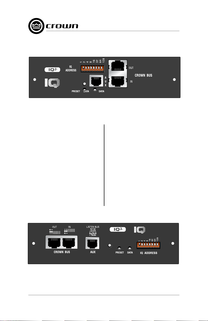
Figure 1.1 IQ-MC4A Front Panel
1 Welcome
The
IQ-MC4A and IQ-MC8
connect CTs 4200 and CTs 8200 amplifiers to the IQ Bus of an
®
, allowing the amplifier to be
tem
controlled and monitored via IQ.
The IQ-MC module is an
component. This means it supports
Crown’s IQ2 protocol and requires an
IQ System with an IQ2
interface. IQ2
ables users and third parties to develop custom software objects to control and monitor IQ2 compatible components like the IQ-MC module.
(universal code) en-
modules
IQ Sys-
IQ2
™ series
-compatible IQ
IQ-MC Modules
Each IQ-MC module includes an IQ
address switch allowing the unit to
have a unique address on the IQ Bus.
It is powered by the amplifier and
includes a memory backup feature
that enables the amplifier to resume
operation with all of its settings intact
after a power outage.
We strongly recommend you read all
the instructions, warnings and cautions contained within. Also, for your
protection, please send in the warranty registration card today and save
the bill of sale since it is your official
proof of purchase.
Reference Manual
Figure 1.2 IQ-MC8 Front Panel
Page 5
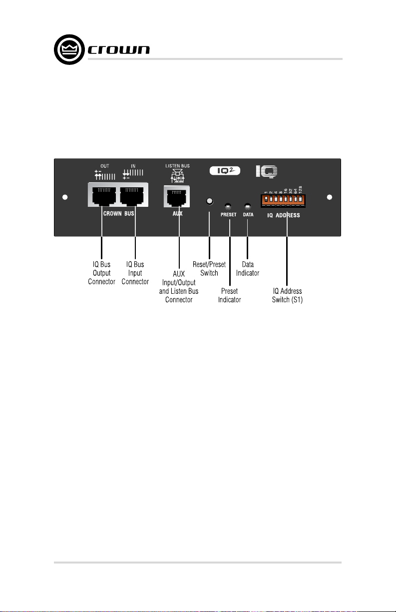
2 Controls, Connectors & Indicators
IQ-MC Modules
Page 6
Figure 2.1 IQ-MC8 Controls, Connectors and Indicators
Reference Manual
3 Installation
IQ-MC Modules
3.1 Prepare the IQ-MC
Module
First, turn off and unplug the amplifier.
Set the IQ address switch S1. By
giving each IQ component a unique
address, it can be individually con-
trolled and monitored. Whenever the
IQ System wants to send a command
to just one IQ component, it first sends
its address and then the command
down the IQ Bus.
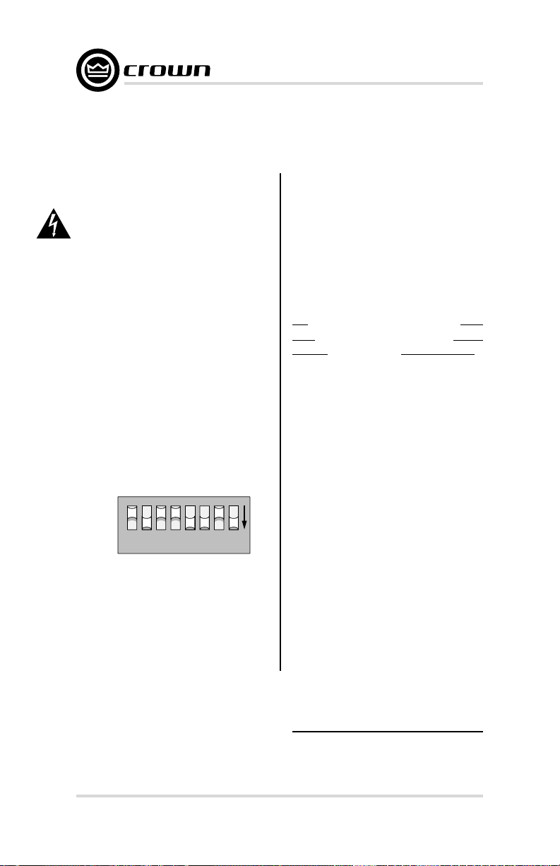
S1 has eight segments because it
actually contains eight tiny switches
inside. The word “ON” is printed on
the switch along its lower left side to
indicate the ON position and the
switches are numbered along the
bottom (Figure 3.1).
124
VALUE
SW1
12345678
Figure 3.1 Address Switch (S1)
Each of the eight switches in S1 has a
value which doubles as the switch
number increases. For example
switch 1 has a value of 1; switch 2 has
a value of 2; switch 3 has a value of 4;
switch 4 has a value of 8 and so on.
8163264128
ON
The address is determined by adding
the values of all “ON” switches. In
Figure 3.1, switches 1, 3, 4 and 7 are
on. Simply add the values to find the
address: 1+4+8+64=77.
A convenient series of IQ address
tables are included in Section 6. The
tables show the switch settings for all
250 addresses.
No two IQ components of the same
type which are connected to the same
IQ Bus can have the same address.*
Suppose, for example, an IQ System
has two IQ Bus loops, 1 and 2, and
this IQ-MC module is to be installed
into loop 1 and given an address of
77. No other IQ-MC modules can be
given the same address in loop 1.
However, an IQ-MC module in loop 2
can have the same address.
Different IQ components in the same
IQ Bus loop can have the same ad-
dress. For example, both an IQ–USM
810 mixer/processor and an IQ-MC
module can use address 77 in the
same loop.
A valid IQ address is any number from
1 to 250. Do not use a number higher
than 250 since they are reserved for
special use. An address of “0” (zero)
should only be used for “stand alone”
mode. Setting the address switch to
“0” disables the IQ Bus port.
Reference Manual
* Note: All IQ PIP™ modules (IQ-PIP-USP2,
IQ-PIP-MEM, IQ-PIP-SMT, etc.) are considered the same type, and so may not share
the same address on the same IQ Bus.
Page 7
IQ-MC Modules
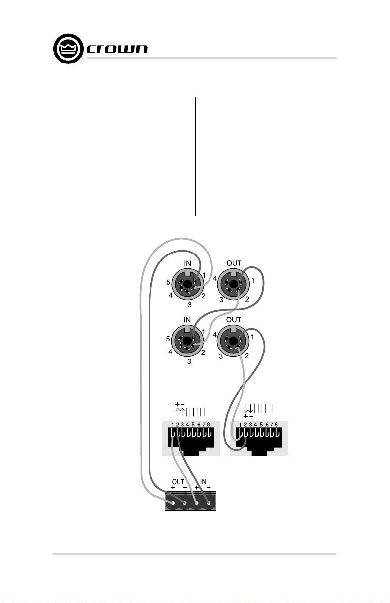
3.2 Install the Wiring
Connect the IQ-MC module to the IQ
system via the IQ Bus. The IQ components in a IQ Bus loop are wired
sequentially. The loop begins and
ends with the IQ interface. The output
of one IQ component “loops” to the
input of the next and so on as shown
in Figure 3.2.
IQ Interface
IQ Component
There are three different types of connectors used for IQ Bus wiring on IQ
components. These include DIN con-
nectors, screw terminal plugs, and
RJ-45 connectors. The IQ-MC uses
RJ-45 connectors that accept stan-
dard RJ-45 plugs like the one shown
in Figure 3.6, allowing the use of industry-standard straight-thru type
network cables. The right RJ-45 con-
nector is used for input and the left RJ45 connector is used for daisy output.
Page 8
OUT
MC-IQ
IQ Component
Figure 3.2 Standard IQ Bus Wiring “Loops” from the Output to
the Input of each IQ Component (for Hub-Style IQ Bus wiring)
IN
Reference Manual
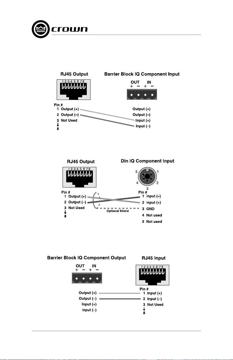
IQ-MC Modules
The following examples show how to connect the MC-IQ to other IQ components:
Figure 3.3 RJ-45 Output to Barrier Block Input
Figure 3.5 RJ-45 Input to Barrier Block Output
Reference Manual
Figure 3.4 RJ-45 Output to Din Input
Page 9
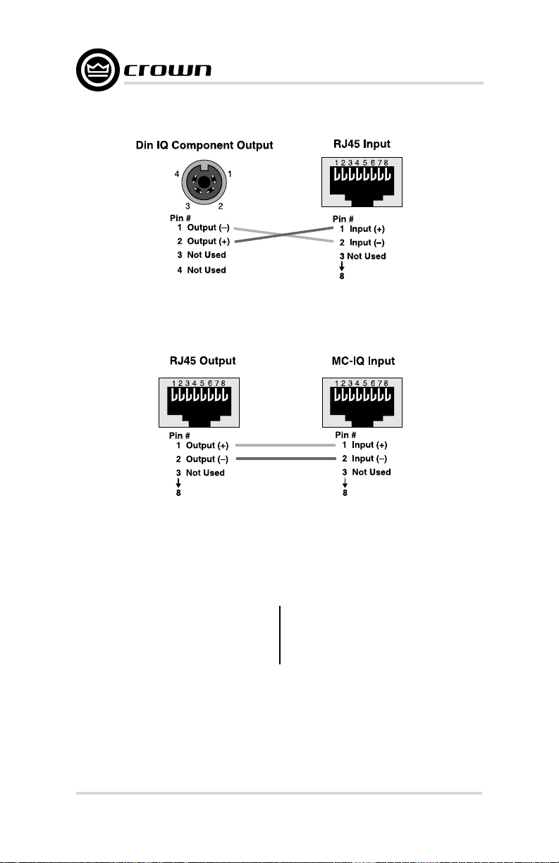
Figure 3.6 RJ-45 Input to Din Output
IQ-MC Modules
Figure 3.7 RJ-45 Output to RJ-45 Intput
3.3 Adjust System Levels
Adjust attenuator levels both on the
amplifier and on the IQ-MC module
Page 10
control panels within your IQ software for optimum system gain.
Reference Manual
 Loading...