

Page 1
*AMB-5 / *SMX-6
ENABLEDATA
ENABLEDATA
IQ Mixer/Multiplexers with Automatic Signal Processing
Printed on
recycled paper.
© 1999 by Crown International, Inc., P.O. Box 1000, Elkhart, Indiana 46515-1000 U.S.A. Telephone:
219-294-8000. The
™
IQ2
is a trademark and
International, Inc. Other trademarks are the property of their respective owners.
IQ–AMB-5 and IQ–SMX-6
Crown
®
,
IQ System
are produced by Crown International, Inc. Trademark Notice:
®
,
Com-Tech
®,
and
®
PZM
are registered trademarks of Crown
126869-1
8/99
Page 2

3
YEAR
THREE YEAR
FULL WARRANTY
3
YEAR
WORLDWIDE
The Crown Audio Division of Crown International, Inc., 1718 West
Mishawaka Road, Elkhart, Indiana 46517-4095 U.S.A. warrants to you,
the ORIGINAL PURCHASER and ANY SUBSEQUENT OWNER of
each NEW Crown
of purchase by the original purchaser (the “warranty period”) that the
new Crown product is free of defects in materials and workmanship, and
we further warrant the new Crown product regardless of the reason for
failure, except as excluded in this Crown Warranty.
1
Note: If your unit bears the name “Amcron,” please substitute it for the
name “Crown” in this warranty.
ITEMS EXCLUDED FROM THIS CROWN WARRANTY
This Crown Warranty is in effect only for failure of a new Crown product
which occurred within the Warranty Period. It does not cover any product
which has been damaged because of any intentional misuse, accident,
negligence, or loss which is covered under any of your insurance
contracts. This Crown Warranty also does not extend to the new Crown
product if the serial number has been defaced, altered, or removed.
We will remedy any defect, regardless of the reason for failure (except
as excluded), by repair, replacement, or refund. We may not elect refund
unless you agree, or unless we are unable to provide replacement, and
repair is not practical or cannot be timely made. If a refund is elected,
then you must make the defective or malfunctioning product available to
us free and clear of all liens or other encumbrances. The refund will be
equal to the actual purchase price, not including interest, insurance,
closing costs, and other finance charges less a reasonable depreciation
on the product from the date of original purchase. Warranty work can
only be performed at our authorized service centers. We will remedy the
defect and ship the product from the service center within a reasonable
time after receipt of the defective product at our authorized service
center.
You must notify us of your need for warranty service not later than ninety
(90) days after expiration of the warranty period. All components must
be shipped in a factory pack. Corrective action will be taken within a
reasonable time of the date of receipt of the defective product by our
authorized service center. If the repairs made by our authorized service
center are not satisfactory, notify our authorized service center
immediately.
YOU ARE NOT ENTITLED TO RECOVER FROM US ANY
INCIDENTAL DAMAGES RESULTING FROM ANY DEFECT IN THE
NEW CROWN PRODUCT. THIS INCLUDES ANY DAMAGE TO
ANOTHER PRODUCT OR PRODUCTS RESULTING FROM SUCH A
DEFECT.
No person has the authority to enlarge, amend, or modify this Crown
Warranty. This Crown Warranty is not extended by the length of time
which you are deprived of the use of the new Crown product. Repairs
and replacement parts provided under the terms of this Crown Warranty
shall carry only the unexpired portion of this Crown Warranty.
We reserve the right to change the design of any product from time to
time without notice and with no obligation to make corresponding
changes in products previously manufactured.
No action to enforce this Crown Warranty shall be commenced later than
ninety (90) days after expiration of the warranty period.
THIS STATEMENT OF WARRANTY SUPERSEDES ANY OTHERS
CONTAINED IN THIS MANUAL FOR CROWN PRODUCTS.
Telephone: 219-294-8200. Facsimile: 219-294-8301
SUMMARY OF WARRANTY
1
product, for a period of three (3) years from the date
WHAT THE WARRANTOR WILL DO
HOW TO OBTAIN WARRANTY SERVICE
DISCLAIMER OF CONSEQUENTIAL
AND INCIDENTAL DAMAGES
WARRANTY ALTERATIONS
DESIGN CHANGES
LEGAL REMEDIES OF PURCHASER
9/90
NORTH AMERICA
The Crown Audio Division of Crown International, Inc., 1718 West Mishawaka
Road, Elkhart, Indiana 46517-4095 U.S.A. warrants to you, the ORIGINAL
PURCHASER and ANY SUBSEQUENT OWNER of each NEW Crown product,
for a period of three (3) years from the date of purchase by the original purchaser
(the “warranty period”) that the new Crown product is free of defects in materials
and workmanship. We further warrant the new Crown product regardless of the
reason for failure, except as excluded in this Warranty.
This Crown Warranty is in effect only for failure of a new Crown product which
occurred within the Warranty Period. It does not cover any product which has
been damaged because of any intentional misuse, accident, negligence, or loss
which is covered under any of your insurance contracts. This Crown Warranty
also does not extend to the new Crown product if the serial number has been
defaced, altered, or removed.
We will remedy any defect, regardless of the reason for failure (except as
excluded), by repair, replacement, or refund. We may not elect refund unless you
agree, or unless we are unable to provide replacement, and repair is not practical
or cannot be timely made. If a refund is elected, then you must make the defective
or malfunctioning product available to us free and clear of all liens or other
encumbrances. The refund will be equal to the actual purchase price, not
including interest, insurance, closing costs, and other finance charges less a
reasonable depreciation on the product from the date of original purchase.
Warranty work can only be performed at our authorized service centers or at the
factory. We will remedy the defect and ship the product from the service center
or our factory within a reasonable time after receipt of the defective product at our
authorized service center or our factory. All expenses in remedying the defect,
including surface shipping costs in the United States, will be borne by us. (You
must bear the expense of shipping the product between any foreign country and
the port of entry in the United States and all taxes, duties, and other customs fees
for such foreign shipments.)
You must notify us of your need for warranty service not later than ninety (90) days
after expiration of the warranty period. All components must be shipped in a
factory pack, which, if needed, may be obtained from us free of charge. Corrective
action will be taken within a reasonable time of the date of receipt of the defective
product by us or our authorized service center. If the repairs made by us or our
authorized service center are not satisfactory, notify us or our authorized service
center immediately.
YOU ARE NOT ENTITLED TO RECOVER FROM US ANY INCIDENTAL
DAMAGES RESULTING FROM ANY DEFECT IN THE NEW CROWN
PRODUCT. THIS INCLUDES ANY DAMAGE TO ANOTHER PRODUCT OR
PRODUCTS RESULTING FROM SUCH A DEFECT. SOME STATES DO NOT
ALLOW THE EXCLUSION OR LIMITATIONS OF INCIDENTAL OR
CONSEQUENTIAL DAMAGES, SO THE ABOVE LIMITATION OR
EXCLUSION MAY NOT APPLY TO YOU.
No person has the authority to enlarge, amend, or modify this Crown Warranty.
This Crown Warranty is not extended by the length of time which you are deprived
of the use of the new Crown product. Repairs and replacement parts provided
under the terms of this Crown Warranty shall carry only the unexpired portion of
this Crown Warranty.
We reserve the right to change the design of any product from time to time without
notice and with no obligation to make corresponding changes in products
previously manufactured.
THIS CROWN WARRANTY GIVES YOU SPECIFIC LEGAL RIGHTS, YOU
MAY ALSO HAVE OTHER RIGHTS WHICH VARY FROM STATE TO STATE.
No action to enforce this Crown Warranty shall be commenced later than ninety
(90) days after expiration of the warranty period.
ITEMS EXCLUDED FROM THIS CROWN WARRANTY
DISCLAIMER OF CONSEQUENTIAL AND INCIDENTAL DAMAGES
THIS STATEMENT OF WARRANTY SUPERSEDES ANY OTHERS
CONTAINED IN THIS MANUAL FOR CROWN PRODUCTS.
Telephone: 219-294-8200. Facsimile: 219-294-8301
SUMMARY OF WARRANTY
WHAT THE WARRANTOR WILL DO
HOW TO OBTAIN WARRANTY SERVICE
WARRANTY ALTERATIONS
DESIGN CHANGES
LEGAL REMEDIES OF PURCHASER
9/90
Page 3

AMB-5 / SMX-6 IQ Mixer/Multiplexer
1) Read these instructions.
2) Keep these instructions.
3) Heed all warnings.
4) Follow all instructions.
5) Do not use this apparatus near water.
6) Clean only with a dry cloth.
7) Do not block any ventilation openings. Install in accordance
with the manufacturer’s instructions.
8) Do not install near any heat sources such as radiators, heat
registers, stoves, or other apparatus that produce heat.
9) Do not defeat the safety purpose of the polarized or grounding-type plug. A polarized plug has two blades with one wider
than the other. A grounding-type plug has two blades and a
third grounding prong. The wide blade or the third prong is
provided for your safety. If the provided plug does not fit into
your outlet, consult an electrician for replacement of the obsolete outlet.
10) Protect the power cord from being walked on or pinched, particularly at plugs, convenience receptacles, and the point
where they exit from the apparatus.
11) Only use attachments/accessories specified by the manufacturer.
12) Use only with a cart, stand, bracket, or table specified by the
manufacturer, or sold with the apparatus. When a cart is used,
use caution when moving the cart/apparatus combination to
avoid injury from tip-over.
13) Unplug this apparatus during lightning storms or when unused
for long periods of time.
14) Refer all servicing to qualified service personnel. Servicing is
required when the apparatus has been damaged in any way,
such as power-supply cord or plug is damaged, liquid has
been spilled or objects have fallen into the apparatus, the apparatus has been exposed to rain or moisture, does not operate normally, or has been dropped.
Important Safety Instructions
Reference Manual
Page 3IQ–AMB-5 / IQ–SMX-6
Page 4
AMB-5 / SMX-6 IQ Mixer/Multiplexer
The information furnished in this manual does not include all of the details of design, production,
or variations of the equipment. Nor does it cover every possible situation which may arise during
installation, operation or maintenance. If you need special assistance beyond the scope of this
manual, please contact our Technical Support Group.
Crown Audio Technical Support Group
Plant 2 SW, 1718 W. Mishawaka Rd., Elkhart, Indiana 46517 U.S.A.
Phone: 800-342-6939 (North America, Puerto Rico and Virgin Islands) or 219-294-8200
Fax: 219-294-8301 Fax Back (North America only): 800-294-4094 or 219-293-9200
Fax Back (International): 219-294-8100 Internet: http://www.crownintl.com email: iqsupport@crownintl.com
WARNING
TO REDUCE THE RISK OF ELECTRIC
SHOCK, DO NOT EXPOSE THIS
EQUIPMENT TO RAIN OR MOISTURE!
PLEASE NOTE
The following universal symbols may appear on your product and/or in various
sections of this manual. Wherever they appear, they are to be interpreted as follows:
Lightning Bolt Symbol:
This symbol is used to alert the user to the presence of dangerous
voltages and the possible risk of electric shock.
Exclamation Mark Symbol:
This symbol is used to alert the user to refer to the instruction
manual for important operating or maintenance instructions.
FCC Class A Compliance
This equipment has been tested and found to comply with the limits for Class A
Digital Device, pursuant to Part 15 of the FCC rules. These limits are designed to
provide reasonable protection against harmful interference when the equipment is
operated in a commercial environment. This equipment generates, uses and can
radiate radio frequency energy and, if not installed and used in accordance with the
instruction manual, may cause harmful interference to radio communications. Operation of this equipment in a residential area is likely to cause harmful interference
in which case the user will be required to correct the interference at his own expense.
The user is cautioned that any changes or modifications not expressly approved by
the party responsible for compliance could void the user’s authority to operate the
equipment.
Note: For a system to comply with FCC rules, all components in the system must be
in compliance. Please consult the instruction manuals of all components in an IQ
System for FCC compliance.
Page 4 IQ–AMB-5 / IQ–SMX-6
Reference Manual
Page 5

AMB-5 / SMX-6 IQ Mixer/Multiplexer
This procedure is provided for those who are already familiar with Crown’s
IQ System
®
and who would like to install the mixer/multiplexer in the
shortest time possible. Less experienced installers or those wishing a full
explanation of the installation procedure are encouraged to go to Section
3 where the full installation procedure is described.
Prepare the mixer/multiplexer:
1 Set the IQ address switch (Figure 3.3) on the mixer/multiplexer to
an unused IQ address.
3 If the mixer/multiplexer is to be used as a system interface, set the
baud rate and parity switches.
Mounting:
4 Mount the unit into a standard 19-inch (48.3-cm) equipment rack or
cabinet, or it can be stacked.
Install the wiring:
5 Connect the mixer/multiplexer to the IQ System via the Crown Bus,
or directly to the host computer if the mixer/multiplexer is to be used
as the system interface (see Section 3.1 if more information is
needed).
6 Turn off all amplifiers or other equipment that will either feed or be
connected to the unit
7 Connect the audio wiring to the mixer/multiplexer inputs and out-
puts.
8 Connect any circuits to be used with the AUX connector to the unit.
9 Connect the unit to the AC receptacle.
Prepare the audio system:
10 Set all equalizers, filters, delays and any other processing equip-
ment the will be in the signal chain before or after the mixer/multiplexer.
11 Set and verify all level and gain settings on all amplifiers or other
equipment that will either feed or be connected to the unit
Configure the mixer/multiplexer:
12 Set input selector switches for Mic, Line, or Phantom, depending
upon input signal to be fed to the input.
13 Set gain levels on the back of the unit.
14 Use IQ software to set up the mixer/multiplexer software-controlled
features.
Quick Install Procedure
.
.
Reference Manual
Page 5IQ–AMB-5 / IQ–SMX-6
Page 6

AMB-5 / SMX-6 IQ Mixer/Multiplexer
CONTENTS
Quick Install Procedure ................................................................. 5
1 Welcome ......................................................................................... 8
1.1 Unpacking .............................................................................. 8
2 Controls, Connectors & Indicators ................................................ 9
3 Hardware Installation ................................................................... 10
3.1 Connecting to a Host Computer ............................................ 10
3.2 Connecting to the Crown Bus ................................................ 11
3.2.1 Set the IQ Address Switch .......................................... 11
3.2.2 Connect to the IQ System via the Crown Bus .............. 12
3.3 Connect the Audio Wiring ...................................................... 14
3.6 Connect Auxiliary Devices .................................................... 14
4 Operation ...................................................................................... 15
4.1 Hardware .............................................................................. 15
4.1.1 IQ Address Switch .......................................................... 15
4.1.2 Baud Rate and Parity Switch ........................................... 15
4.1.3 Enable Indicator.............................................................. 15
4.1.4 DATA Indicator ................................................................ 15
4.1.5 Main Audio Inputs ........................................................... 15
4.1.6 Sense Input ..................................................................... 15
4.1.7 Main Audio Outputs ........................................................ 15
4.1.8 Bus Outputs .................................................................... 15
4.1.9 Stack Audio Inputs .......................................................... 15
4.1.10 Crown Bus Connector ..................................................... 16
4.1.11 Crown Bus Ground Connector ........................................ 16
4.1.12 RS232 Serial Port ........................................................... 16
4.1.13 Sensing AUX Port ........................................................... 16
4.2 Computerized Control and Monitoring
4.2.1 Manual/Auto Mode .......................................................... 16
4.2.2 Input Level Monitors ........................................................ 16
4.2.3 Output Level Monitors ..................................................... 16
4.2.4 Bus Output Relays .......................................................... 16
4.2.5 VCA Gain Controls .......................................................... 16
Automatic Mixing Features
4.2.6 Gate ................................................................................ 16
4.2.7 Duck Priority ................................................................... 17
4.2.8 Input Compressor ........................................................... 17
4.2.9 Auto Level....................................................................... 17
4.2.10 Output Compressor ........................................................ 18
4.2.11 Gate Count ..................................................................... 18
4.2.12 Ambience .......................................................................
4.3 Crown Local Net ................................................................... 19
18
5 Technical Information .................................................................. 19
5.1 Audio 19
5.1.1 Input Section .............................................................. 19
5.1.2 VCA Sections .............................................................. 19
5.1.3 Output Section ............................................................ 20
5.1.4 Level Sense Circuits ................................................... 20
5.2 Control and Interface Section ................................................ 20
5.2.1 Crown Bus Interface ....................................................... 20
5.2.2 RS232 Interface .............................................................. 20
5.2.3 D/A Converter ................................................................. 20
5.2.4 Log Amp and A/D Converter ........................................ 20
Page 6 IQ–AMB-5 / IQ–SMX-6
Reference Manual
Page 7

AMB-5 / SMX-6 IQ Mixer/Multiplexer
5.3 Auxiliary Port ......................................................................... 20
6 IQ Audio In Depth ......................................................................... 23
6.1 A Closer Look at Audio Signal Wiring ........................................ 23
6.1.1 Input ............................................................................... 23
6.1.2 IQ–AMB-5 Ambient Sensing Input ................................... 24
6.1.3 Ouput ............................................................................. 24
6.1.4 Stack Inputs .................................................................... 25
6.1.5 Paralleling Inputs ............................................................ 26
6.2 Using the AUX Port ............................................................... 27
6.3 The Mixer/Multiplexer as IQ Interface .................................... 28
6.4 Crown Local Net ................................................................... 28
6.4.1 Wiring the Crown Local Net ........................................ 28
6.5 A Closer Look at Crown Bus Wiring ....................................... 29
7 IQ Address Tables ........................................................................ 30
8 Factory Service ............................................................................ 32
Illustrations
Figure 1.1 The IQ–AMB-5 and IQ–SMX-6 ........................................................ 8
Figure 2.1 IQ Mixer / Multiplexer Controls, Connectors & Indicators ................ 9
Figure 3.1 IQ System with Host Computer and Two Mixer/Multiplexers ......... 10
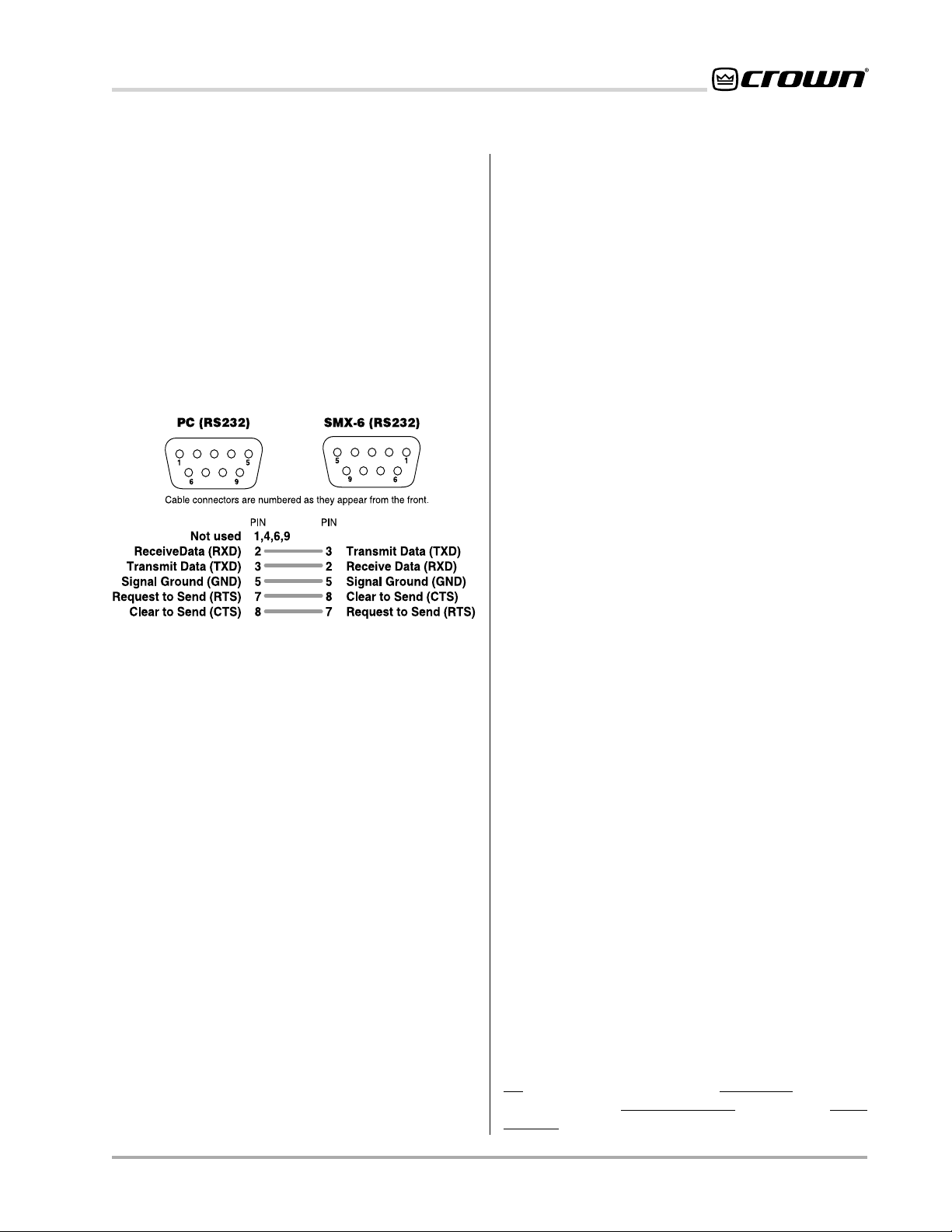
Figure 3.2 RS232 Cable Wiring ..................................................................... 11
Figure 3.3 Selecting IQ Address and Communication Parameters ................ 12
Figure 3.4 Four-Terminal Removable Barrier Block Plug ................................ 13
Figure 3.5 Crown Bus Wiring for Removable Barrier Blocks .......................... 13
Figure 3.6 Crown Bus Wiring for 5-pin DIN Input ........................................... 13
Figure 3.7 Crown Bus Wiring for RJ-45 Input ................................................ 13
Figure 3.8 Crown Bus Wiring for 4-pin DIN Output ........................................ 13
Figure 3.9 Crown Bus Wiring for RJ-45 Output.............................................. 13
Figure 3.10 Crown Bus Wiring “Loop” from Output to Input ............................. 14
Figure 5.1 IQ–AMB-5 Block Diagram ............................................................ 21
Figure 5.2 IQ–SMX-6 Block Diagram ............................................................ 22
Figure 6.1 An Audio Input Section ................................................................ 23
Figure 6.2 Suggested Audio Input Gain Control Settings .............................. 23
Figure 6.3 Balanced Audio Input Wiring ........................................................ 23
Figure 6.4 Unbalanced Audio Input Wiring ................................................... 24
Figure 6.5 Sensing Input Section .................................................................. 24
Figure 6.6 Audio Output Section ................................................................... 25
Figure 6.7 Balanced Audio Output Connections ........................................... 25
Figure 6.8 Unbalanced Audio Output Connections ....................................... 25
Figure 6.9 A 12x2 Mixer Using 2 Mixer/Multiplexers ...................................... 25
Figure 6.10 Stacking the Outputs of Multiple Units .......................................... 26
Figure 6.11 A 6x8 Mixer Using 4 Mixer/Multiplexers ........................................ 26
Figure 6.12 Paralleling the Inputs of Multiple Units .......................................... 26
Figure 6.13 A 12x8 Mixer Using 8 Mixer/Multiplexers ...................................... 26
Figure 6.14 Sample Auxiliary System Wiring ................................................... 27
Figure 6.15 Internal Auxiliary Circuit ................................................................ 27
Figure 6.16 A Crown Local Net RS232 Serial Loop ......................................... 28
Figure 6.17 Crown Local Net Wiring ............................................................... 28
Figure 7.1 IQ Address Switch Settings from 0 to 125..................................... 30
Figure 7.2 IQ Address Switch Settings from 126 to 250................................. 31
Reference Manual
Page 7IQ–AMB-5 / IQ–SMX-6
Page 8
Figure 1.1 The IQ–AMB-5 and IQ–SMX-6
AMB-5 / SMX-6 IQ Mixer/Multiplexer
ENABLEDSPI
ENABLEDSPI
1 Welcome
Thank you for purchasing a
Crown
®
IQ mixer/multiplexer. IQ mixer/multiplexers are intelligent mixers with
special signal routing capabilities. Their intelligence
stems from a powerful onboard microprocessor which
enables them to be controlled by a Crown
IQ System
Each input and output can be individually controlled
and, with their
distributed intelligence
™
capability, continue to operate even when an IQ System is not connected.
In addition to two main outputs (one for each channel),
each model has a second set of “bus” outputs which
are switched on and off by a relay. This enables many
mixer/multiplexers to be connected to a common audio bus without loading it down. They are designed to
work as stand-alone units in a small audio system, or
as modules in a large audio system.
Two models are available to serve different needs. The
IQ–SMX-6
AMB-5
™
model operates as a 6x2 mixer. The
™
can operate as a 5x1 mixer. Multiple units can
IQ–
be connected together to form larger mixers. For example, two IQ–SMX-6 mixers can be connected together to form a single 12x2 mixer.
The IQ–SMX-6 provides basic mixing capabilities, as
well as automatic signal processing. A sensing circuit
is located at the beginning of each input to sense the
input signal level ahead of any signal processing. Similar sensors, along with its onboard intelligence, enable
the IQ–SMX-6 to perform many versatile functions like
automatic mixing, compression, and automatic level
control.
Page 8 IQ–AMB-5 / IQ–SMX-6
The IQ–AMB-5 has the same functions as an IQ–SMX6 plus it has the ability to sense ambient sound level
and automatically adjust its output level accordingly. In
this way it serves as the ultimate automatic level con-
®
troller. Input 6 is dedicated as the sensing input, leav-
.
ing 5 inputs to function normally as a 5x2 mixer. Unlike
the IQ–SMX-6, signal processing is only available for
Channel 1. Channel 2 functions as a manual mixer.
This manual will help you successfully install your unit.
Please read all the instructions, warnings and cautions
contained within it. Also, for your protection, please
send in the warranty registration card today. And save
the bill of sale—it is your official proof of purchase.
1.1 Unpacking
Please inspect the unit for any damage that may have
occurred during transit. If damage is found, notify the
transportation company immediately. Only you, the
consignee, may initiate a claim with the carrier for
shipping damage. Crown will cooperate fully as
needed. Save the shipping carton as evidence of
damage for the shipper’s inspection.
Please save all packing materials. NEVER SHIP THE
UNIT WITHOUT THE FACTORY PACK.
Reference Manual
Page 9
AMB-5 / SMX-6 IQ Mixer/Multiplexer
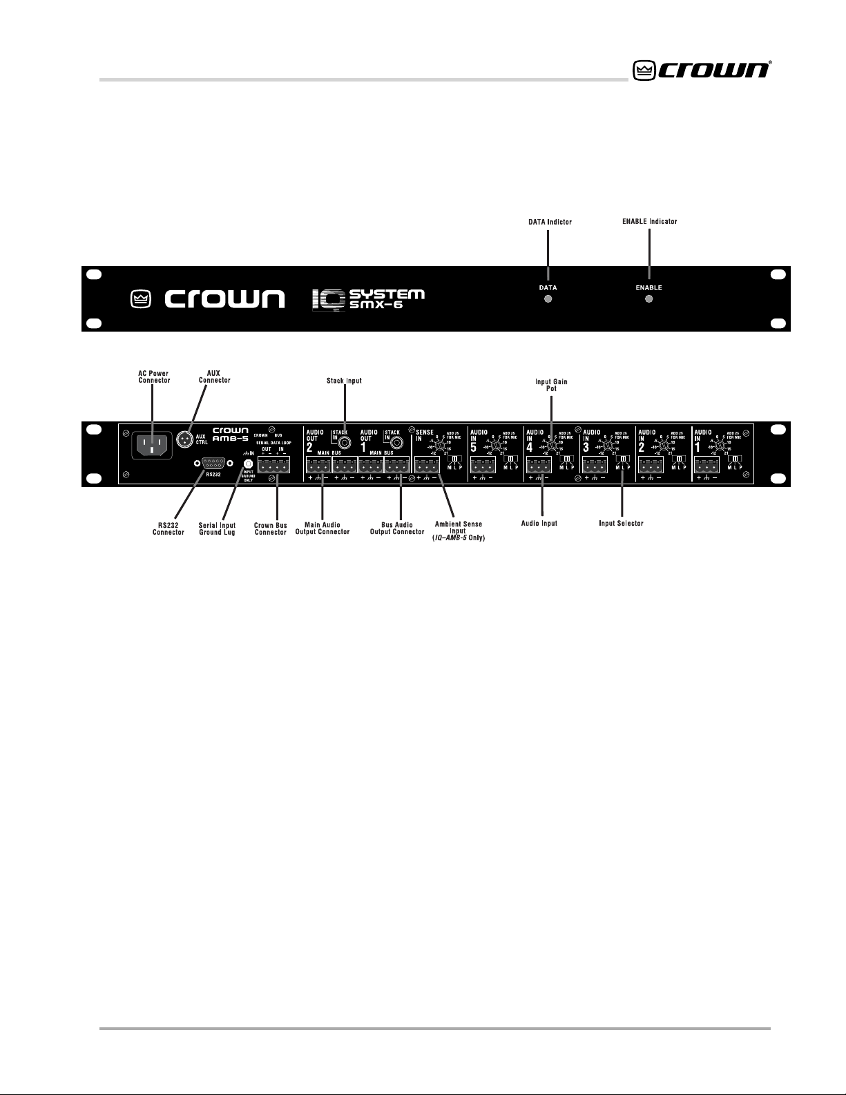
2 Controls, Connectors & Indicators
Figure 2.1 IQ Mixer / Multiplexer Controls, Connectors & Indicators
Reference Manual
Page 9IQ–AMB-5 / IQ–SMX-6
Page 10

RS232
AMB-5 / SMX-6 IQ Mixer/Multiplexer
ENABLEDSPI
ENABLE
ODEP
CH1 CH2
CH1 CH2
CH1 CH2
IOC
SPI
ODEP
IOC
SPI
ODEP
IOC
SPI
POWER
OFF
ENABLE
POWER
OFF
ENABLE
POWER
OFF
Figure 3.1 An IQ System with a Host Computer and Two Mixer/Multiplexers
3 Hardware Installation
The installation of an IQ mixer/multiplexer consists of
two major parts: installing the hardware and configuring the software. This manual deals only with hardware
installation. Refer to the appropriate software documentation for instructions in setting up and operating
your IQ software.
Provide adequate cooling if the unit will be used in a
hot environment. It is good practice to allow one
empty rack space (1.75 inches or 4.4 cm.) between
each unit if more than four units will be stacked in a
cabinet. Each empty rack space should be sealed
with a blank rack panel.
The hardware installation is divided into 4 steps: 1)
connecting to a host computer 2) connecting to the
Crown Bus 3) connecting the audio inputs and outputs
and 4) connecting auxiliary devices
3.1 Connecting to a Host Computer (Step 1)
An IQ host computer is an IBM® PC-compatible computer which is used is used to configure or control/
monitor part or all of an IQ System. Depending upon
the design of your IQ System, it may or may not require
a host computer during normal operation.
ENABLEDSPI
ENABLE
ODEP
IOC
SPI
CH1 CH2
ODEP
IOC
SPI
CH1 CH2
POWER
OFF
ENABLE
POWER
OFF
CROWN BUS LOOP 1
ENABLE
ODEP
IOC
SPI
CH1 CH2
POWER
OFF
CROWN BUS LOOP 2
How the mixer/multiplexer will be used will determine
whether or not it will need to be connected directly to a
host computer. If the unit will be connected to the
Crown Bus it will not need to be connected directly to a
host computer. The following circumstances require
connection to a host computer:
• If a Crown Bus will not be used, the mixer/multiplexer will need to be connected to a host computer so the software inside the unit can be
configured. Afterward, if manual control is not
required, the host computer can be disconnected.
• If the mixer/multiplexer must be configured before it is installed into an IQ System, it must be
connected directly to a host computer for configuration. The onboard memory of the unit will
maintain its software configuration without it
being plugged into an AC source.
• If the mixer/multiplexer will be used as an IQ
interface for other IQ–AMB-5 or IQ–SMX-6 mixers, it will need to be connected directly to a
host computer.
Page 10 IQ–AMB-5 / IQ–SMX-6
Reference Manual
Page 11
AMB-5 / SMX-6 IQ Mixer/Multiplexer
One of the advantages of connecting directly to a host
computer is that a separate IQ interface (IQ–INT-II) is
not required. If you plan to configure the unit while it is
connected to the Crown Bus, skip ahead to Section
3.2.
RS232 is commonly used with IBM PCs and compatibles, and is the communication standard supported by the mixer/multiplexer when used as an
interface. Because it uses unbalanced signal wiring, it
cannot be used for distances over 50 feet (15.2 m).
The following illustration shows how to wire the serial
cable:
• Use the highest baud rate possible. IQ mixer/
multiplexers can be set as high as 19.2 K baud.
• If the host computer fails to communicate with the
unit and the communication standard and parameters are set correctly, try reducing the baud
rate of both the unit and the computer.
• If communication problems persist, check the serial cable for improper wiring or possible shorted
or broken wires.
• For further assistance contact the Crown Technical Support Group (see Section 8 for contact information.)
3.2 Connecting to the Crown Bus (Step 2)
The Crown Bus is a serial communication loop designed to transmit IQ commands and data. As a communication standard, it is independent of the wiring
system used. This flexibility is a great strength, enabling a Crown Bus loop to be wired with either fiber
optic cabling or with inexpensive twisted-pair wire,
whichever the installation requires. A single
can have more than one Crown Bus loop. To function
properly, a Crown Bus loop must be unbroken.
IQ System
Figure 3.2 RS232 Cable Wiring
Important: Do not use twisted pair wire for RS232
because it increases crosstalk. Instead, use an untwisted cable or ribbon cable.
Setting the communication parameters for RS232 serial communication is accomplished using the six-segment baud rate and parity DIP switch shown in Figure
3.3. The first four switches select the baud rate and the
last two set the parity. Use the fastest baud rate possible. The highest baud rate supported by the unit is
19.2 K baud. Parity checking is not supported and
should be OFF. The odd/even parity bit setting doesn't
matter when parity is switched OFF. The unit has been
factory set to 1 stop bit and 8 data bits.
The communication parameters of the host computer
are set by the IQ software. Please refer to the IQ
software documentation for information about setting
up communication parameters.
Here are some important guidelines when configuring
serial communication:
• Use the same communication parameters at
each end. The unit and the computer must be set
for the same baud rate and parity checking.
3.2.1 Set the IQ Address Switch
By giving each IQ component a unique address, it can
be individually controlled and monitored. Whenever
the IQ System wants to send a command to just one IQ
component, it first sends its address and then the
command down the Crown Bus.
The IQ Address switch has eight segments because it
actually contains eight tiny switches inside. The switch
is shown in Figure 3.3.
Each of the eight segments in the IQ Address switch
have a value which doubles as the number increases.
For example segment 1 has a value of 1; segment 2
has a value of 2; segment 3 has a value of 4; segment
4 has a value of 8 and so on.
The address is determined by adding the values of all
“ON” segments. In Figure 3.3, segments 2, 5, 6, and 7
are on. Simply add the values to find the address:
2+16+32+64=114.
A convenient series of IQ address tables are included
in Section 7. The tables show the switch settings for all
250 addresses.
No two IQ components of the same type which are
connected to the same Crown Bus can have the same
address. Suppose, for example, an IQ System has two
Reference Manual
Page 11IQ–AMB-5 / IQ–SMX-6
Page 12

AMB-5 / SMX-6 IQ Mixer/Multiplexer
Crown Bus loops, 1 and 2, and an IQ–SMX-6 is to be
installed into loop 1 and given an address of 114. No
other IQ–SMX-6 can be given the same address in
loop 1. However, an IQ–SMX-6 in loop 2 can have the
same address.
Different IQ components in the same Crown Bus loop
can have the same address. For example, both an IQ–
SMX-6 and an IQ–AMB-5 can use address 114 in the
same loop.
A valid IQ address is any number from 1 to 250. Do not
use a number higher than 250 since they are reserved
for special use. An address of “0” (zero) should never
be used.
3.2.2 Connect the mixer/multiplexer to the IQ System
via the Crown Bus
The IQ components in a Crown Bus loop are wired
sequentially. The loop begins and ends with the IQ
interface. The output of one IQ component “loops” to
the input of the next and so on as shown in Figure 3.10.
There are three different types of connectors used for
Crown Bus wiring on IQ components. These include
DIN connectors, RJ-45 connectors, and removable
barrier strip plugs. IQ mixer/multiplexers use four terminal removable barrier strip connectors that accept
plugs like the one shown in Figure 3.4.
Figure 3.3 Selecting the IQ Address and Communication Parameters
Page 12 IQ–AMB-5 / IQ–SMX-6
Reference Manual
Page 13

AMB-5 / SMX-6 IQ Mixer/Multiplexer
3
/16 in
(0.48 cm)
Figure 3.4 Four-Terminal Removable Barrier Block Plug
The following examples show how to connect the
mixer/multiplexer to other IQ components on the
Crown Bus:
Figure 3.7 Crown Bus Wiring for RJ-45 Input
Mixer/Multiplexer 1
1
34
2
Cable connectors are numbered as they appear from the front.
PIN
Input (–)
Input (+)
Output (–)
Output (+)
1
2
3
4
Optional Shield
Mixer/Multiplexer 2
1
34
2
PIN
Input (–)
1
Input (+)
2
3
Output (–)
4
Output (+)
GNDGND
Figure 3.5 Crown Bus Wiring for Removable Barrier
Blocks
4-pin Removable Barrier
Block (Mixer/Multiplexer)
1234
5-pin DIN Input
1
2
5
4
3
Cable connectors are numbered as they appear from the front.
4-pin DIN Output
4-pin Removable Barrier
Block (Mixer/Multiplexer)
PIN
1
2
3
4
4
3
1234
PIN
Input (–)
1
Input (+)
2
Output (–)
Optional Shield
3
4
Output (+)
GND
1
2
Cable connectors are numbered as they appear from the front.
GND
Output (+)
(Not Used)
(Not Used)
Figure 3.8 Crown Bus Wiring for 4-pin DIN Output
Input (–)
Input (+)
Output (–)
Output (+)
GND
PIN
1
2
3
4
l
e
i
h
S
l
a
n
o
i
t
p
O
PIN
1
Input (–)
2
Input (+)
GND
3
(Not Used)
d
4
(Not Used)
5
Figure 3.6 Crown Bus Wiring for 5-pin DIN Input
Reference Manual
Figure 3.9 Crown Bus Wiring for RJ-45 Output
Page 13IQ–AMB-5 / IQ–SMX-6
Page 14

AMB-5 / SMX-6 IQ Mixer/Multiplexer
3.3 Connect the Audio Wiring (Step 3)
IQ mixer/multiplexers have 6 mic/line inputs and 2
stack inputs (Input 6 of the IQ–AMB-5 is dedicated for
ambient sensing). Two audio channels feed two main
and two auxiliary bus outputs. Three-terminal removable barrier block connectors are provided for the mic/
line inputs and main and bus outputs. RCA-type
phono jacks are provided for the stack inputs. See
Section 5.1 for information on the operation of the
mixer/multiplexer inputs and outputs.
O
I
D
U
A
N
I
3.4 Connect Auxiliary Devices (Step 4)
Connect any external circuits you plan to use to
control the AUX input and/or monitor the AUX output
of the mixer/multiplexer. See section 5.2 for
information on the operation of the AUX input and
output and for examples of wiring circuits to the AUX
connector.
Important: Provide adequate
cooling if the unit will be used in a
hot environment. It is good prac-
tice to allow one empty rack
space (1.75 inches or 4.4 centi-
meters) between each unit if
more than four units will be
stacked in a cabinet. Each empty
rack space should be sealed with
a blank rack panel to facilitate
proper air flow inside the cabinet.
Figure 3.10 Crown Bus Wiring “Loop”from Output to Input of Each IQ Component
Page 14 IQ–AMB-5 / IQ–SMX-6
Reference Manual
Page 15

AMB-5 / SMX-6 IQ Mixer/Multiplexer
4 Operation
The IQ–AMB-5 and IQ–SMX-6 sensing mixer/multiplexers are IQ components that can be controlled
and monitored from a remote location via an IQ
System. In addition to basic mixing functions, the
IQ–AMB-5 and IQ–SMX-6 sensing mixer/multiplexers offer advanced signal processing and have the
capability of mixing audio signals automatically. The
IQ–SMX-6 is a 6x2 automatic mixer, with computer
controlled input switching and routing capabilities.
The IQ–AMB-5 features many of the same automatic
functions as the IQ–SMX-6, with the added ability to
sense and compensate for ambient noise levels.
The IQ–AMB-5 operates as a 5x1 automatic mixer
with the sixth input reserved for ambient level sensing. In addition, it operates as a passive 6x1 mixer
that is output independently to channel 2, ideal for
monitoring purposes. Both models can be integrated with other like units to form larger composite
mixers.
The following sections describe the IQ–AMB-5 and
IQ–SMX-6 features and their operation. Where
specified, some features are accessed via controls
located on the unit itself; however, most of the features are configured and controlled using IQ software. Please contact your Crown representative or
Crown's Technical Support Group if you are unfamiliar with IQ software.
4.1 Hardware
4.1.1 IQ Address Switch
A 8-segment DIP switch is used to set the IQ address of the unit. The unit must be given a unique IQ
address so it can be independently controlled and
monitored by the system. It must also be set properly if an IQ–SMX-6 is to be used in a Crown Local
Net. Two or more IQ components should NEVER
have the same address on the same Crown Bus
loop. See section 3.2.1 for more information about
setting the IQ address. Important: The IQ address
should only be set with the power cord disconnected from the AC supply.
4.1.2 Baud Rate and Parity Switch
A 6-section DIP switch is used to set the baud rate
and parity for RS232 serial communication. This is
only necessary when the unit is to serve as system
interface. Important: The baud rate should only be
set with the power cord disconnected from the
AC supply.
4.1.3 Enable Indicator
The front panel Enable indicator lights up to show
that the unit is plugged in and AC power is being
supplied.
4.1.4 DATA Indicator
The front panel DATA indicator lights up to show that
digital information is being received by the internal
processor from an external source (Crown Bus or
serial computer port). A DATA indicator also appears in IQ software, and can be forced to remain lit
as a helpful diagnostic tool.
4.1.5 Main Audio Inputs
Three-terminal removable barrier block connectors
are provided for the audio inputs. Each input has a
three-position M/L/P selector switch for mic level,
line level, or mic level with +44 VDC phantom power.
Select the left position (M) for microphone signal
levels up to +7 dBu (o dBu = 0.775 volts). Select the
center position (L) for line level signals up to +32
dBu. Select the right position (P) to provide 44 VDC
to mics requiring phantom power.
4.1.6 Sense Input (IQ–AMB-5 only)
The IQ–AMB-5 has a Sense input in place of one of
the Main inputs. This input is identical in all respects
to a Main input, except for the internal routing of the
audio after the gain stages. The Sense input does
not enter the output channel 1 mix, although it can
enter the output channel 2 mix (as a sixth main
input). The sense input is used to “sense” ambient
noise levels through a connected microphone. The
IQ–AMB-5 uses this signal to automatically adjust
other input levels to compensate for changes in
ambient noise level.
4.1.7 Main Audio Outputs
a 3-pin removable barrier block plug is used to
connect to the main output of each channel. These
outputs can also be connected to the stack inputs of
other mixer/multiplexers to make a larger mixer.
4.1.8 Bus Outputs
A 3-pin removable barrier block plug is used to
connect to the bus audio output of each channel.
The bus outputs are isolated switchable outputs that
can be turned on when needed by the IQ System.
This allows many multiplexers to be tied together on
the same bus without loading down the outputs.
4.1.9 Stack Audio Inputs
Two unbalanced stack inputs are provided (one per
Reference Manual
Page 15IQ–AMB-5 / IQ–SMX-6
Page 16

AMB-5 / SMX-6 IQ Mixer/Multiplexer
output channel) via RCA pin jacks. Each input enters the mix of the respective output channel at unity
gain, and without manual or computer input control.
These stack inputs allow you to multiply the number
of audio inputs by stacking 2, 3, or more units to
build a larger mixer. See section 5.1.4 for more information about forming larger mixers.
4.1.10 Crown Bus Connector
A 4-pin removable barrier block connector is provided for digital communication via the Crown Bus
serial data loop to other IQ components. A ground
lug is provided to connect an optional shield for the
Crown Bus input.
4.1.11 Crown Bus Ground Connector
This chassis ground stud is provided to connect an
optional shield for the Crown Bus cable. Only the
shield of the input cable should be connected.
Shielded wire will reduce the total distance a Crown
Bus loop can be run, but shielding may be necessary to reduce interference with certain kinds of
audio cables. See section 5.5 for more information
about wiring the Crown Bus.
4.1.12 RS232 Serial Computer Port
A 9-pin DB9 serial computer port is provided for
direct communication with a computer. The mixer/
multiplexer is capable of serving as a system interface for up to 20 IQ mixer/multiplexers.
4.1.13 Sensing AUX Port
A TB-3M type “mini-XLR” connector is provided for
AUX input and output. This port may be used to
provide a control signal or sense a control signal.
Pin 1 is ground reference. Pin 2 is a sensing input. A
signal between +5 to +30 VDC is sensed as a logic
high. Because the circuit floats, the input line must
be tied to ground or a control voltage source to be
used. Pin 3 is output under processor control. When
on, it provides 10 VDC at 16 ma, and when off, it is
effectively an open circuit (high impedance). Section 6.2 describes example applications for the AUX
port.
4.2 Computerized Control and Monitoring
The following features are controlled and monitored
via IQ software.
4.2.1 Manual/Auto Mode
This feature switches the mixer/multiplexer between
Manual and Automatic modes. When in Manual
mode, you may make changes from software that
affect VCA gain in real time. Gain may also be manipulated in real time from alternate third-party control systems or devices. In manual mode, once VCA
gains are set via the PC (or control device) the
processor maintains those settings until it receives
an instruction to change.
4.2.2 Input Level Monitors
Audio level monitors are provided for each input.
The level is sensed between the preamp and VCA's,
with a range of –40 to +25 dBu.
4.2.3 Output Level Monitors
Audio level monitors are provided for each output.
The level is sensed at each output mix bus with a
range of –40 to +25 dBu.
4.2.4 Bus Output Relays
Audio bus outputs can be switched on and off with
software controlled isolation relays.
4.2.5 VCA Gain Controls
Each input may be routed to either or both outputs
by VCAs under processor control. The processor
may, in turn, be set up to control VCAs using on
board automatic intelligence or may be controlled in
real time manually from software. The VCAs offer a
control range of –100 to +25 dB.
Automatic Mixing Features
The following features make up the Automatic Mixing Feature Set, and are only functional when the
mixer/multiplexer is in Auto mode. All features are
common to the IQ–AMB-5 and IQ–SMX-6 unless
otherwise stated.
4.2.6 Gate
The gate feature shuts off or attenuates inputs when
not in use. This feature is particularly useful to prevent feedback caused by too many open microphone channels. There are four parameters which
control this feature:
• Max Gain control: used to set the maximum
gain for an input to one of the two outputs when
Auto is turned on. The Max Gain setting has
different effects when different Auto functions
are active. For example, when the Gate function is activated the Max Gain will be the “gate
open” level. When then Input Compressor/Limiter function is activated, it acts as the “limit,”
the upper gain achieved when no compression
is taking place.* Control range is from –100 to
Page 16 IQ–AMB-5 / IQ–SMX-6
Reference Manual
Page 17

AMB-5 / SMX-6 IQ Mixer/Multiplexer
+25 dB in 1/2-dB steps.
••
• Gate Threshold: the input level above which
••
the gate will “open” and below which the gate
will “close.” Control range is from –100 to +25
dB in 1/2-dB steps.
• Low Set: the gain setting that will be used
when the gate is “closed.” Control range is
from –100 to +25 dB in 1/2-dB steps.
• Delay: determines how long the gate will stay
open after the incoming signal drops below the
Threshold. Control range is from 0.2 to 30 seconds.
4.2.7 Duck Priority
“Ducking” is the attenuation of an input when another input with a higher priority is activated by the
Gate function. When the higher priority gate opens,
all inputs with lower priorities drop or “duck” to their
Low Set values. Up to six levels of priority can be
established between input channels. With the IQ–
SMX-6, each output channel can have a different
priority structure. There are two different parameters
which control this feature:
• Duck Priority On/Off: turns this feature on or
off.
• Duck Priority Level: a setting from 1 to 6
where 1 is highest priority and 6 is lowest priority. Each VCA is set independently.
4.2.8 Input Compressor
The input compressor/limiter function “reins in”
input signals that suddenly become too loud.
The compressor is a feed-forward type, which
performs the compression after the level sensor. This allows it to work more smoothly than
conventional-type compressors. There are parameters which control this feature:
• Compressor/Limiter On/Off: This control
turns the function on or off for the indicated input/output channel.
• Max Gain: the gain setting when no compression is taking place. Control range is from –100
to +25 in 1/2-dB steps.
• Threshold: the input level above which compression begins. A signal at this level or below
is not affected. Control range is from –100 to
+25 in 1/2-dB steps.
* There is only one Max Gain that is shared among all of the Auto functions
that use it. This means that if you change the Max Gain on one page of the
Auto functions, the Max Gain is changed for all pages.
• Compression Ratio: the amount of compression that is applied for every step over the
Threshold. Choices are 1:1, 2:1, 4:1, 8:1, 16:1,
32:1, infinity:1.
• Release Time: determines how long it takes for
the gain to return to normal once the level
drops below the Threshold. Control range is
from 0.2, to 30 seconds.
• Slow Compression (IQ–SMX-6 only): This
control applies to all input channels. When
Slow Compression is set to off, the compressor
is set to the fastest attack time possible. This
will be very fast—so fast the compressor can
stop extremely sudden transients like the
sound caused by a dropped microphone. This
is a good setting for rapid speech. You can
turn the Slow Compression on for more gentle
sound sources such as most music.
4.2.9 Auto Level
Auto Level is designed to control long-term changes
in signal level. With Auto Level on, the average
output level can be kept relatively constant over a
longer time interval while transients are allowed to
pass. Auto Level creates a more natural sound with
increased dynamic range. There are five different
parameters which control this feature:
• Auto Level On/Off: This control turns the function on or off for the indicated input/output
channel.
• Max Gain: the upper limit for input gain. This
level serves as a gain “ceiling” when the Auto
Level function is attempting to raise the gain on
a low-level signal. Control range is from –100 to
+25 in 1/2-dB steps
• Auto Level control: sets the desired average
output level. This level can best be understood
as a “target” level. If the output signal level is
above this level, the gain will be reduced to attempt to hit this target. Likewise, if the output
signal is lower than this level, the gain will be
increased. In no case will the gain level be set
to greater than Max Gain. Control range is from
–100 to +25 in 1/2-dB steps.
• Idle Gain: controls the initial gain when the
gate first opens. Idle Gain can be thought of as
the “starting gain” because it overrides the Max
Gain when the gate opens, and can compensate for undesirable side-effects caused by
Max Gain being set above the Auto Level
value. Start with Idle Gain equal to Max Gain.
Reference Manual
Page 17IQ–AMB-5 / IQ–SMX-6
Page 18

AMB-5 / SMX-6 IQ Mixer/Multiplexer
If the level audibly drops each time the gate
opens, try a lower value for Idle Gain. Idle gain
should never be set to a value greater than Max
Gain. Control range is from –100 to +25 in 1/2dB steps.
• Reaction Time: the time in seconds to adjust
gain 10 dB toward the necessary gain structure
to obtain the desired average output level.
Control range is from 0.2, to 30 seconds.
• Auto Level Gate Function: a global setting
that may be set to “Open To Idle Gain” or
“Open To Last Position.” When set to “Open To
Idle Gain” an input will initially gate on to the
Idle Gain setting and the auto level feature will
take over from that point. When set to “Open To
Last Position” the auto level feature remembers
the gain of the VCA at the time the input last
gated off so that gain goes back to that level
the next time the gate opens.
4.2.10 Output Compressor
The Output Compressor/Limiter function keeps the
output from exceeding a predetermined level. It's
especially valuable when used as an output limiter
for the protection of amplifiers, loudspeakers and
other audio equipment. Compression of the signal at
each input occurs only when the mix exceeds the
limit threshold. There are six parameters which control this feature:
• Compressor: a master ON/OFF switch for
each output that enables or disables output
compression for that output.
• Limiter:
an ON/OFF switch for each VCA that
configures which inputs may participate in output compression.
••
• Limit Threshold: used to set the peak signal
••
level above which compression occurs. Control range is from –100 to +25 in 1/2 dB steps.
••
• Compression Ratio: controls the amount of
••
compression that is applied for every step over
the Threshold. Choices are 1:1, 2:1, 4:1, 8:1,
16:1, 32:1, infinity:1.
••
• Release Time: determines how long it takes for
••
the gain to return to normal when the level
drops below the Threshold. Control range is
from 0.2 to 30 seconds.
••
• Max Gain: the gain setting of the input when no
••
compression is active. Control range is from –
100 to +25 in 1/2-dB steps.
4.2.11 Gate Count
The Gate Count function keeps track of how many
gates are open at a time, and provides feedback
control when a large number of inputs are open.
The Gate function must be on for the Gate Count to
operate. There are four parameters which control
this feature:
Gate Count Master: a master ON/OFF switch for
each output that enables or disables gate
counting for that output.
Gate Count: an ON/OFF switch for each VCA
that configures which inputs may participate in
the gate count.
Gate Count Level: determines how much each
input is attenuated as more gates open. When
only one mic in a count group is active, there is
no added attenuation. Each additional open
mic increases the attenuation by the “Count
Level.” Control range is from 0.5 to 16 dB.
Max Gain: the gain setting that will be used when
the gate is “open,” and no further attenuation is
indicated. Control range is from –100 to +25 in
1
/2-dB steps.
4.2.12 Ambience (IQ–AMB-5 only)
The Ambience function monitors the ambient sense
input (Input 6) and automatically adjusts the mix
output level of Channel 1 up or down accordingly.
This enables the IQ–AMB-5 to automatically mix and
control the overall loudness in an environment with
background noise levels that vary. Functionally, the
ambience function operates after all other functions
have processed the audio signals. There are six
parameters which control this feature:
Ambience: an On/Off switch that enables of dis-
ables the Ambience feature
• Attack Time: determines how rapidly the Ambience function will begin to increase the output level of Channel 1 above the Ambient offset
level once the level of Input 6 exceeds the
Threshold. Control range is from 0.2 to 30 seconds.
• Decay Time: determines how rapidly the Ambience function will begin to reduce the output
level of Channel 1 while the ambient sense input level is dropping. Control range is from 0.2
to 30 seconds.
• Expansion Ratio: determines how much the
gain of output Channel 1 will increase for every
Page 18 IQ–AMB-5 / IQ–SMX-6
Reference Manual
Page 19

AMB-5 / SMX-6 IQ Mixer/Multiplexer
increase in the ambient signal level above the
Threshold setting. A 4:1 Expansion Ratio setting will raise the output gain 1 dB for every 4
dB that the ambient signal increases. Choices
are 1:1, 1.5:1, 2:1, 2.5:1, 3:1, 4:1, and 5:1.
• Threshold: determines at what ambient sound
level the Ambience function will begin to operate. It is the sound pressure level of the ambient sensing input (Input 6). When the signal
level of Input 6 exceeds the Threshold setting,
the Ambience function begins to increase the
gain of Channel 1 at a rate dictated by the Expansion Ratio control. Control range is from
–100 to +25 dB in 1/2-dB steps.
• Ambient Offset: the level below Max Gain to
which the Channel 1 gain will be set until the
ambience level exceeds the Threshold setting.
As the ambience level increases above the
Threshold setting, the Channel 1 gain will be
increased above the Ambient Offset according
to the Expansion Ration setting. The Max Gain
setting always limits the maximum possible
gain which any input can receive. Control
range is from 0 to +40 dB in 1/2-dB steps.
4.3 Crown Local Net (IQ–SMX-6 only)
The Crown Local Net (CLN) allows multiple IQ–SMX6 units to be linked so that their Duck Priority and
Gate Count functions work together. For example, a
duck priority 1 in one unit will override a priority 2 in
another unit. Likewise on the gate count side, the
number of open mics can be totaled among all the
IQ–SMX-6 units in a CLN and all open inputs attenuated to prevent feedback in a large system. Use of
this feature requires that the serial port of each IQ–
SMX-6 be dedicated to CLN use, meaning that if the
IQ–SMX-6 is to be used with CLN, it cannot be used
as a system interface. Successful setup of a CLN
requires that the setup be performed in a particular
sequence of steps. Please refer to the IQ software
documentation for setup procedures. There are five
parameters which control this feature:
• System On/Off: activates the Crown Local
Net. This control should only be turned on
for the first time after all of the following parameters have been set. Please refer to the
IQ software documentation for setup procedures.
• Master On/Off: selects the master IQ–SMX-6
as required by the start-up procedure. Only
one IQ–SMX-6 should be the master. Neither
the Crown Local Net nor the IQ–SMX-6 units
will function properly if more than one unit is selected as a master.
• External Functions On/Off: setting this control
to ON allows the IQ–SMX-6 to participate in the
Crown Local Net.
• Duck On/Off: setting this control to ON allows
the IQ–SMX-6 to respond to external Duck Priority functions.
• Gate Count On/Off: setting this control to ON
allows the IQ–SMX-6 to respond to external
Gate Count functions.
5 Technical Information
Following is a technical description of the operation of
the IQ–AMB-5 and IQ–SMX-6 mixer/multiplexers. Refer to the block diagrams on the following pages for
illustration of signal flow.
5.1 Audio
5.1.1 Input Section
Each audio input signal first passes through a balanced filter designed to eliminate RF interference. The
RF filters are a balanced network of chokes, ferrite
beads and capacitors that attenuate both commonmode and differential-mode signals above 500 kHz.
Optional input isolation transformers can also be
added by the factory.
The signal then enters the input switching circuit. This
circuit can insert a 25 dB pad for line level signals or
apply phantom power to the input terminals (44 volts
through two 6810 ohm resistors). The signal is filtered
again to eliminate lower-frequency RF energy such as
interference from the AM broadcast band. The signal
then goes to the preamp stage.
Each of the six input preamplifier stages is a balanced
circuit providing from 13 to 46 dB of voltage gain. The
preamp consists of a pair of low-noise transistors, followed by a high performance op-amp. The transistors,
in effect, convert the input voltage to a current while
maintaining reasonably high input impedance. Their
transconductance (output current divided by input
voltage) depends on the setting of the gain control.
The op-amp then converts the current back to a voltage to drive subsequent circuits.
5.1.2 VCA Sections
Each preamplifier output drives two VCAs which then
Reference Manual
Page 19IQ–AMB-5 / IQ–SMX-6
Page 20

AMB-5 / SMX-6 IQ Mixer/Multiplexer
drive the two current-summing mix buses. The stack
inputs also feed into the mix buses. The VCA's derive
their control voltages from a multiplexer circuit driven
from the microprocessor. The microprocessor uses
onboard
algos
or commands from a host computer to
control the VCAs. Levels can be set in 1/2 dB increments from 25 dB gain to 100 dB attenuation (which is
considered “off”).
5.1.3 Output Section
The two mix buses are sent to the corresponding main
output and auxiliary bus output stages. All output
stages are active, balanced and can drive 1200 ohms
to +26 dBu or 600 ohms to +20 dBu. The auxiliary bus
output stages have internal relay contact which can
connect or disconnect the signal to the auxiliary bus
output connector. These contacts are controlled by the
host computer and thus allow programmed signal
routing. Optional output isolation transformers can also
be added by the factory.
5.1.4 Level Sense Circuits
The output of each input preamp and each mix amp is
monitored by a corresponding level detector. Each
level detector tracks the peak level of the signal and
releases with a time constant of about 85 ms. The eight
levels are sent to a multiplexer and the A/D converter.
5.2 Control and Interface Section
The host computer communicates with the unit microprocessor either through an outboard IQ interface (like
the IQ–INT-II) via the Crown Bus, or directly through the
RS232 port. Each unit acts only on commands with an
address matching its own.
5.2.3 D/A Converter
To set channel gain levels, a digital-to-analog converter continuously converts all gain settings to control
voltages. An analog de-multiplexer sends the appropriate control voltages to each of the twelve VCAs.
5.2.4 Log Amp and A/D Converter
The A/D converter scans through an eight-channel
multiplexer to read the input and output signal levels.
When a channel is selected, the signal is sent through
a logarithmic amplifier for increased dynamic range.
This analog voltage is then converted to a binary number that the microprocessor can read. The processor
can then mathematically increase detector time constraints, perform averaging or other response functions.
5.3 Auxiliary Port
Auxiliary devices such as supplemental cooling fans
can be remotely controlled via the AUX output on the
unit. When the auxiliary control feature is turned on by
the host computer, 10 VDC is supplied across pin 3
and pin 1 (ground) of the male 3-pin AUX connector.
This port can control solid state relays, and since it has
a current-limit resistor (16 mA max.), it can directly
drive an LED or opto-coupler.
The AUX input function is used by applying a 5-30
VDC signal to pin 2 (with pin 1 as ground). A high or
low signal here will be communicated to the host computer. A logic low can be less than 0 volts (negative);
the signal is internally clamped for circuit protection.
5.2.1 Crown Bus Interface
The serial loop (Crown Bus) connections on the unit
are made with an opto-isolated 4-pin removable barrier block connector and a ground stud for the optional
connection of shielded wire. To prevent ground loops,
only the input cable's shield should be connected.
These connections conform to IQ System standards,
which allow the host computer to control numerous IQ
components with the same computer program.
5.2.2 RS232 Interface
Depending on selected options, the DB9 connector
can be used to communicate directly with the host
computer for setup or control of a Crown Bus loop, or
(IQ–SMX-6 only) for connection to an RS232 Crown
Local Net.
Page 20 IQ–AMB-5 / IQ–SMX-6
Reference Manual
Page 21

AMB-5 / SMX-6 IQ Mixer/Multiplexer
Reference Manual
Figure 5.1 IQ–AMB-5 Block Diagram
Page 21IQ–AMB-5 / IQ–SMX-6
Page 22

AMB-5 / SMX-6 IQ Mixer/Multiplexer
Figure 5.2 IQ–SMX-6 Block Diagram
Page 22 IQ–AMB-5 / IQ–SMX-6
Reference Manual
Page 23

AMB-5 / SMX-6 IQ Mixer/Multiplexer
6 IQ Audio In Depth
This section provides additional information about
Crown’s IQ System with special guides to aid in the
installation and use of the IQ–AMB-5/IQ–SMX-6. For
more information about any of these topics, contact
the Crown Technical Support Group.
6.1 A Closer Look at Audio Signal Wiring
6.1.1 Input
Three-terminal removable barrier block connectors are
provided for the audio inputs. Each input has an input
selector switch. Slide it to the left (M) for microphone
signal levels up to +7 dBu (0 dBu = 0.775 volts). Select
the center position (L) for line level signals up to +32
dBu. Slide it to the right (P) to provide 44 VDC to mics
requiring phantom power.
source. Setting the source signal level to approximately 0 dBu will provide 20 dBu of headroom in the
input preamp. Some recommended settings are given
in Figure 6.2.
Figures 6.3-4 show the normal wiring for balanced and
unbalanced inputs. It is also possible to parallel the
inputs of multiple units to increase the number of mixer
outputs. For example, the inputs of two 6x2 IQ–SMX-6s
can be paralleled to create a 6x4 mixer. This technique
is described in Section 6.1.5.
Figure 6.1 An Audio Input Section
Each input has a screwdriver-set, calibrated gain control to compensate for different input source levels. The
slot on the control shaft points to the gain setting. The
settings are labelled for line-level input. Add 25 dB to
the scale if the inputs are switched for microphone
level signals.
Use a screwdriver to adjust the gain pot so that the
input signal level plus gain equals roughly 0 dBu. You
will need to know, or estimate, the level of the input
oiduAorP
tnempiuqe
VBd/mBd
uBd
detsegguS
gnitteS
0 dBm = 0.775 VRMS with a 600 ohm load, 0 dBV = 1 VRMS, 0 dBu = 0.775 VRMS
mBd4+VBd01VBd57VBd56VBd54VBd55VBd52VBd51VBd5
uBd4+uBd8uBd37uBd38uBd34uBd35uBd32uBd31
)L(4)L(8+)M(12+)M(11+)P(81+)M(12+)P(2)M(21
roorp-imeS
remusnoc
tnempiuqe
cimanyD
hceeps,cim
Figure 6.3 Balanced Audio Input Wiring
resnednoC
hceeps,cim
toH
resnednoc
hceeps,cim
cimanyD
cisum,cim
toH
rosnednoc
cisum,cim
dekim-esolC
cimanyd
,cim
smurd/ssab
dekim-esolC
,cimcimanyd
,murdkcik
pmaratiug
uBd3
ro)M(21
)L(3+
Fig. 6.2 Suggested Audio Input Gain Control Settings
Reference Manual
Page 23IQ–AMB-5 / IQ–SMX-6
Page 24

AMB-5 / SMX-6 IQ Mixer/Multiplexer
Balanced sources should be wired as shown in Figure
6.3. Notice that the shield is not connected to the
chassis ground of the source if the source is also
connected to the AC ground (that is, it has a grounded
AC plug). This prevents unwanted ground loops.
Floating
source
Output
+
Grounded
source
Output
+
Floating
source
Shield connected
to ground terminal
2-wire line cord
(or battery power)
Shield not connected
at this end
3-wire grounded line cord
(or other ground connection)
Shield connected to both negative
(–) and ground input terminals
INPUT
INPUT
+–
+–
Twin-lead shielded cable
5 the paging level at a train station can be automatically adjusted so pages can be heard over the roar of
an incoming train and yet quieted to an appropriate
level during periods of softer ambient sound levels.
The sensing input section of the back panel is shown
in Figure 6.5 below. It has the same features as the
other mic/line inputs: input gain control and input level
switch.
SENSE
IN
+–
Figure 6.5 Sensing Input Section
ADD 25
0
5
FOR MIC
-5
10
-10
15
-12
21
LMP
The most common use of the sensing input is to connect a microphone (such as a Crown
PZM
®
) and locate the microphone so that it can accurately receive
the ambient sound level. Great care must be taken in
the placement of the ambient sensing microphone so
that it is not too close to the loudspeakers being driven
by the system.
Output
+
INPUT
+–
Input ground
terminal not used
INPUT
+–
Single-conductor coax
Grounded
source
Output
+
2-wire line cord
(or battery power)
3-wire grounded line cord
(or other ground connection)
Figure 6.4 Unbalanced Audio Input Wiring
Unbalanced sources should be wired as shown in
Figure 6.4. The examples in Figure 6.4 are grouped
according to whether twin-lead shielded wire or singleconductor coax (and twisted pair) wire is used.
6.1.2 IQ–AMB-5 Ambient Sensing Input
In addition to its automatic mixing capabilities, the IQ–
AMB-5 also has the ability to adjust the output level of
Channel 1 to the ambient sound level. (Remember,
Channel 2 functions manually only). It does this with its
sensing input (input 6). For instance, with an IQ–AMB-
It is also possible to connect more than one ambient
sensing microphone to the sense input. This can be
accomplished by taking advantage of the manual mixing function of Channel 2. Simply connect each ambient sensing microphone to one of the five regular
inputs of the IQ–AMB-5 and use the IQ software to
assign each of them to Channel 2 only. Switch the
sense input to the line-level position (L) and connect
the main audio output of Channel 2 to it. Use the IQ
or twisted pair
software to control the level of the ambient sensing
microphones. The microphones which are located in
more critical areas can be set to a higher level so they
will trigger the level controller first.
Be sure the microphone has adequate sensitivity for
the spectral content of the ambient sound. For example, a microphone with a bandwidth designed
solely for speech reinforcement may not have adequate low-frequency sensitivity to pick up the lowfrequency noise of machinery in a factory.
6.1.3 Output
Three-terminal removable barrier block connectors are
provided for audio output (Figure 3.15). Both “main”
and “bus” outputs are provided for each of the two
mixer channels. They are balanced and can drive 1200
ohms or more to +26 dBu or 600 ohms to +20 dBu.
Page 24 IQ–AMB-5 / IQ–SMX-6
Reference Manual
Page 25

AMB-5 / SMX-6 IQ Mixer/Multiplexer
Each bus output can drive any number of inputs within
this impedance range.
AUDIO
OUT
1
Figure 6.6 Audio Output Section
STACK
IN
MAIN BUS
+–+–
The main audio outputs are provided for connection
with other audio equipment such as power amplifiers.
They can also be “stacked” with the outputs of other
mixer/multiplexers to increase the number of mixer inputs For example, two 6x2 IQ–SMX-6s can be stacked
to create a 12x2 mixer. This is described in Section 6.1.4
The bus outputs are turned on or off by relays and function like the AUX “send” outputs on a conventional mixing console. They are switched on or off by the IQ
System. This special design allows many bus outputs
to be connected to a common audio bus in a multiplezone network (like a large airport paging system). Because the bus outputs are controlled by the IQ System,
they can be kept off until they are actually used, preventing too many of them from being on at the same
time and loading down a common audio bus network.
The versatile bus outputs can be used for any audio
system where switchable outputs are desired, such as
switchable recording outputs.
Both main and bus outputs are wired the same way.
Balanced output wiring is shown in Figure 6.7.
Notice that the shield is not connected to the output
ground terminal if the load is connected to AC ground.
This prevents unwanted ground loops. Unbalanced
output wiring is shown next.
Figure 6.8 Unbalanced Audio Output Connections
6.1.4 Stack Inputs
the “stack in” jacks (Figure 6.6) enable the audio inputs
to be increased by stacking 2, 3 or more mixer/multiplexers to create a 12x2, 18x2 or wider mixer. Use 2conductor shielded cable to route the signal from the
main output of one unit to the stack input (RCA phono
jack) of the second unit. Use the outputs of the last unit
in the stack for connection to amplifiers or other external audio equipment.*
Figure 6.7 Balanced Audio Output Connections
Reference Manual
12 INPUTS
MAIN
STACK
OUT
IN
SMX-6 SMX-6
STACKED
OUTPUTS
2
OUTPUTS
Figure 6.9 A 12x2 Mixer Using 2 Mixer/Multiplexers
Stacking mixer/multiplexers can create an almost unlimited number of inputs; however, there will still only be
two main and two auxiliary bus outputs for connection
to other equipment. See Section 6.1.5 to find output how
to increase the number of outputs.
* The level of each signal on the stacked ouput bus is controlled by the unit
having the signal as an input.
Page 25IQ–AMB-5 / IQ–SMX-6
Page 26

AMB-5 / SMX-6 IQ Mixer/Multiplexer
The correct way to wire stacked units is shown below:
STACK
First
Unit
AUDIO
OUT
2
MAIN
IN
BUS
3-pin output connector
(–) No connection
2-conductor shielded cable
Connect ground ( ) from
output to phone plug shield
Phone (RCA) plug
STACK
Second
Unit
AUDIO
OUT
2
MAIN
IN
BUS
Figure 6.10 Stacking the Outputs of Multiple Units
AUDIO
OUT
1
MAIN BUS
AUDIO
OUT
1
MAIN BUS
STACK
IN
+–+–+–+–
STACK
IN
+–+–+–+–
6.1.5 Paralleling inputs
When using more than one unit, the inputs may be
wired in parallel to increase the number of outputs that
a source can drive. This is shown in Figures 6.11-12.
For example, the audio signal in Figure 6.12 which
feeds Input 1 is available to the outputs of both units,
creating a 6x4 mixer.
6 INPUTS
SMX-6
PARALLELED
INPUTS
SMX-6
SMX-6
8
OUTPUTS
To signal
source
First
Unit
AUDIO
IN
2
0
-5
-10
-12
5
21
ADD 25
FOR MIC
10
15
LMP
AUDIO
IN
1
+
ADD 25
0
0
5
FOR MIC
-5
10
-10
15
-12
21
–
LMP
+–
Do NOT tie ground terminals
of parallel inputs together
2-conductor shielded cable
Connect shield to ground
terminal of input ONLY
Second
Unit
AUDIO
0
IN
-5
-10
2
-12
+– +–
5
21
ADD 25
FOR MIC
10
15
LMP
AUDIO
IN
1
ADD 25
0
0
5
FOR MIC
-5
10
-10
15
-12
21
No
phantom
LMP
power
Figure 6.12 Paralleling the Inputs of Multiple Units
By using several units and a combination of parallel
inputs and stacked outputs, larger mixing configurations (12x8, 24x4, etc.) can be created as shown below:
12 INPUTS
MAIN
STACK
OUT
IN
SMX-6 SMX-6
PARALLELED
INPUTS
SMX-6 SMX-6
SMX-6
SMX-6
SMX-6
SMX-6
8
OUTPUTS
SMX-6
Figure 6.11 A 6x8 Mixer Using 4 Mixer/Multiplexers
6x8
Figure 6.13 A 12x8 Mixer Using 8 Mixer/Multiplexers
STACKED
OUTPUTS
6x8
Important: If the source is a microphone which requires phantom power (P), select it only at the first
input. Switch all other parallel inputs to mic (M).*
* When mixer inputs are paralleled, the total input impedance will drop by 1/
N where N is the number of inputs to be connected. Depending on the signal
source, this may place a limit on the number of possible outputs.
Page 26 IQ–AMB-5 / IQ–SMX-6
Reference Manual
Page 27

AMB-5 / SMX-6 IQ Mixer/Multiplexer
6.2 Using the AUX Port
There are many possible uses for the AUX output. For
example, it can be used to turn on auxiliary cooling
fans. To do this the AUX connector might be used to
close a relay. The relay would then turn the fans on or
off. This is shown in Figure 6.14.
The solid state relay shown (Crown part number D
7308-7) can be ordered from the Crown Parts Department.
The Aux port uses a male 3-pin mini XLR connector
which is located above the DB9 connector (Figure
2.1). Use a Switchcraft® TA3F cable connector or
equivalent to make the connection.
AUX
CONNECTOR
1
3
2
110 VAC
Figure 6.14 Sample Auxiliary System Wiring
GND
10 V
INPUT
+–
SOLID
STATE
RELAY
(C 7308-7)
AUXILIARY
EQUIPMENT
When the Aux port is turned on by the
IQ System
it
provides 10 VDC across pins 3 (+) and 1 (ground). An
internal 1.5 K ohm resistor limits the current to a maximum of 16 mA. This is shown below in Figure 6.15.
Figure 6.15 Internal Auxiliary Circuit
Notice in Figure 6.15 that the AUX connector can be
used to sense the presence of an input signal across
pins 2 (+) and 1 (ground). It is a high impedance input
and includes a pull-down resistor.
Reference Manual
Page 27IQ–AMB-5 / IQ–SMX-6
Page 28

6.3 The Mixer/Multiplexer as a 1-Loop IQ
Interface
The mixer/multiplexer can serve a an IQ interface
between a host computer and a single Crown Bus
loop for other IQ–AMB-5/IQ–SMX-6 units only. This
can eliminate the need for an external IQ Interface
(
IQ-INTII
connects directly to the host computer via the DB9
serial connector. Switches accessed through the
side of the chassis are used to select the parity and
baud rate. See Section 3.2 for specific instructions
on wiring and switch settings.
) in a small system. The mixer/multiplexer
CLN Interface
RS232
AMB-5 / SMX-6 IQ Mixer/Multiplexer
CLN Interface
RS232
CLN Interface
RS232
While 250 IQ components of each type can be controlled on a single Crown Bus loop, it is recommended that no more than 20 units be connected to
an mixer/multiplexer. This is because of the tremendous timing demands on their microprocessors.
More than 20 IQ components may cause timing
problems.
6.4 Crown Local Net (IQ–SMX-6 only)
Crown Local Net (CLN) is available only for an IQ–
SMX-6. It enables multiple IQ–SMX-6s to be interconnected via a CLN. This is an RS232
communication loop designed for local communication between IQ components apart from the Crown
Bus. IQ–SMX-6s can use this option to communicate the total number of open mics in the system as
well as their individual ducking priorities. In this way,
one IQ–SMX-6 will know how many mics are being
used by other IQ–SMX-6s and can take appropriate
action to prevent feedback or implement priority
switching (ducking) of mics.*
6.4.1 Wiring the Crown Local Net
A Crown Local Net is a serial loop (Figure 6.16).
With two exceptions, a Crown Local Net loop is
wired the same as standard RS232 wiring, except
the Crown Local Net does not use handshaking
therefore pins 7 and 8 (RTS/CTS) are not used.
Figure 6.16 A Crown Local Net RS232 Serial Loop
Important: The Crown Local Net must make a
complete loop. If the last unit in a group is not
connected to the first unit, the system will not
function.
Important: The Crown Local Net depends on
proper IQ address assignments, even if the system will not be installed with a Crown Bus loop.
Each unit in a Crown Local Net must have a
different IQ address. See Section 3.2 for details.
As more diverse IQ communications are needed,
the Crown Local Net will be available to move information directly between IQ components without affecting the performance of a host computer.
Figure 6.17 shows the wiring for a 3-unit Crown
Local Net. If more units are desired, simply add
another unit and follow the same pattern for wiring.**
* Because Loop IQ Interface and CLN use the same DB9 connector, they
cannot be used at the same time. This means that IQ–SMX-6s to be used in
a CLN will need to be connected to a Crown Bus via an external IQ interface
for setup.
** Pin 5 should not be used as a ground if the units are already properly
grounded. The wire used for RS232 communication is usually unsuitable for
use as a ground.
Page 28 IQ–AMB-5 / IQ–SMX-6
Figure 6.17 Crown Local Net Wiring
Reference Manual
Page 29

AMB-5 / SMX-6 IQ Mixer/Multiplexer
6.5 A Closer Look at Crown Bus Wiring
The Crown Bus is a serial communication loop designed to transmit IQ commands and data. As implemented in the IQ mixer/multiplexer, it is a 20 mA current
loop operating at a baud rate of 38.4 K.
The Crown Bus connection can use inexpensive
twisted-pair wiring (shielded or unshielded) and it must
be unbroken. If fiber optic cabling is required, contact
the Crown Technical Support Group (see Section 8 for
contact information)
Here are some guidelines for twisted-pair wiring:
• When interference is a problem, use shielded
twisted-pair wire at least 26 AWG in size. The
wire should be of good quality and should have
low capacitance—30 pF/foot or less is good. The
shield serves two purposes: First, it helps prevent
the IQ data signal from transmitting to nearby audio wiring. Second, it helps prevent outside RF
from interfering with the data signal. However, in
most cases interference is not a problem and,
since unshielded wire has lower capacitance, it is
a better choice.
Outside RF interference is seldom a problem for a
Crown Bus loop—especially if shielded twisted-pair
wire is used. However, there are extreme situations
when fiber optic wiring is recommended. For example,
locating a Crown Bus loop next to an AM radio transmission line may require fiber optic cabling. An extremely long Crown Bus loop distance may also
require fiber optic cabling.
• Minimize the total capacitance of a Crown Bus
loop. The total capacitance should be less than
30 nF. Allow approximately 60 pF for each IQ
component in a loop. This accounts for a slight
signal degradation which occurs as data signals
pass through a component.
• Add an IQ Repeater for very long loops—greater
than 1,000 feet (305 m)—or when required by
high-capacitance wire. Although we recommend
adding a repeater for loops longer than 1,000
feet, it is often possible to go 2,000 feet (610 m) or
more. The most significant characteristic of the
wire is its capacitance. Lower capacitance allows
longer loops. Unshielded wire usually has less
capacitance.
• Never use the ground wire in a mic snake line.
It may sometimes be convenient to run Crown
Bus data signals to and from stage monitor amplifiers along unused wire pairs in a mic snake. Do
not use the ground wire which is normally connected to pin 1 on an XLR connector or data
noise will be added to the audio lines. Use only
the signal lines which normally connect to pins 2
and 3 of the XLRs.*
* Because typical mic cables have high capacitance, the maximum possible
Crown Bus loop distance will be less.
Reference Manual
Page 29IQ–AMB-5 / IQ–SMX-6
Page 30

7 IQ Address Tables
This section contains lookup tables for every valid IQ address. The valid addresses are 1 to 250. Do not use an
address number higher than 250! Addresses above 250
are reserved for special system use.
Remember: No two IQ components of the same type
AMB-5 / SMX-6 IQ Mixer/Multiplexer
which are connected to the same Crown Bus loop can
have the same address.
To use the IQ address tables, simply find the address
you want and set the IQ address switch of the mixer/
multiplexer as described in Section 3.2.1.
IQ
Address
0
1
2
3
4
5
6
7
8
9
10
11
12
13
14
15
16
17
18
19
20
21
22
23
24
25
26
27
28
29
30
31
32
33
34
35
36
37
38
39
40
41
IQ Address Switch
1
2
3
4
OFF
OFF
OFF
OFF
ON
OFF
OFF
OFF
OFF
ON
OFF
OFF
ON
ON
OFF
OFF
OFF
OFF
ON
OFF
ON
OFF
ON
OFF
OFF
ON
ON
OFF
ON
ON
ON
OFF
OFF
OFF
OFF
ON
ON
OFF
OFF
ON
OFF
ON
OFF
ON
ON
ON
OFF
ON
OFF
OFF
ON
ON
ON
OFF
ON
ON
OFF
ON
ON
ON
ON
ON
ON
ON
OFF
OFF
OFF
OFF
ON
OFF
OFF
OFF
OFF
ON
OFF
OFF
ON
ON
OFF
OFF
OFF
OFF
ON
OFF
ON
OFF
ON
OFF
OFF
ON
ON
OFF
ON
ON
ON
OFF
OFF
OFF
OFF
ON
ON
OFF
OFF
ON
OFF
ON
OFF
ON
ON
ON
OFF
ON
OFF
OFF
ON
ON
ON
OFF
ON
ON
OFF
ON
ON
ON
ON
ON
ON
ON
OFF
OFF
OFF
OFF
ON
OFF
OFF
OFF
OFF
ON
OFF
OFF
ON
ON
OFF
OFF
OFF
OFF
ON
OFF
ON
OFF
ON
OFF
OFF
ON
ON
OFF
ON
ON
ON
OFF
OFF
OFF
OFF
ON
ON
OFF
OFF
ON
OFF
OFF
OFF
OFF
OFF
OFF
OFF
OFF
OFF
OFF
OFF
OFF
OFF
OFF
OFF
OFF
ON
ON
ON
ON
ON
ON
ON
ON
ON
ON
ON
ON
ON
ON
ON
ON
OFF
OFF
OFF
OFF
OFF
OFF
OFF
OFF
OFF
OFF
5
IQ
6
7
8
Address
OFF
OFF
OFF
OFF
OFF
OFF
OFF
OFF
OFF
OFF
OFF
OFF
OFF
OFF
OFF
OFF
OFF
OFF
OFF
OFF
OFF
OFF
OFF
OFF
OFF
OFF
OFF
OFF
OFF
OFF
OFF
OFF
OFF
ON
ON
ON
ON
ON
ON
ON
ON
ON
ON
OFF
OFF
OFF
OFF
OFF
OFF
OFF
OFF
OFF
OFF
OFF
OFF
OFF
OFF
OFF
OFF
OFF
OFF
OFF
OFF
OFF
OFF
OFF
OFF
OFF
OFF
OFF
OFF
OFF
OFF
OFF
OFF
OFF
OFF
OFF
OFF
OFF
OFF
OFF
OFF
OFF
OFF
OFF
OFF
OFF
OFF
OFF
OFF
OFF
OFF
OFF
OFF
OFF
OFF
OFF
OFF
OFF
OFF
OFF
OFF
OFF
OFF
OFF
OFF
OFF
OFF
OFF
OFF
OFF
OFF
OFF
OFF
OFF
OFF
OFF
OFF
OFF
OFF
OFF
OFF
OFF
OFF
OFF
42
43
44
45
46
47
48
49
50
51
52
53
54
55
56
57
58
59
60
61
62
63
64
65
66
67
68
69
70
71
72
73
74
75
76
77
78
79
80
81
82
83
IQ Address Switch
1
2
3
4
OFF
ON
OFF
ON
ON
ON
OFF
ON
OFF
OFF
ON
ON
ON
OFF
ON
ON
OFF
ON
ON
ON
ON
ON
ON
ON
OFF
OFF
OFF
OFF
ON
OFF
OFF
OFF
OFF
ON
OFF
OFF
ON
ON
OFF
OFF
OFF
OFF
ON
OFF
ON
OFF
ON
OFF
OFF
ON
ON
OFF
ON
ON
ON
OFF
OFF
OFF
OFF
ON
ON
OFF
OFF
ON
OFF
ON
OFF
ON
ON
ON
OFF
ON
OFF
OFF
ON
ON
ON
OFF
ON
ON
OFF
ON
ON
ON
ON
ON
ON
ON
OFF
OFF
OFF
OFF
ON
OFF
OFF
OFF
OFF
ON
OFF
OFF
ON
ON
OFF
OFF
OFF
OFF
ON
OFF
ON
OFF
ON
OFF
OFF
ON
ON
OFF
ON
ON
ON
OFF
OFF
OFF
OFF
ON
ON
OFF
OFF
ON
OFF
ON
OFF
ON
ON
ON
OFF
ON
OFF
OFF
ON
ON
ON
OFF
ON
ON
OFF
ON
ON
ON
ON
ON
ON
ON
OFF
OFF
OFF
OFF
ON
OFF
OFF
OFF
OFF
ON
OFF
OFF
ON
ON
OFF
OFF
OFF
OFF
OFF
OFF
OFF
OFF
ON
ON
ON
ON
ON
ON
ON
ON
ON
ON
ON
ON
ON
ON
ON
ON
OFF
OFF
OFF
OFF
OFF
OFF
OFF
OFF
OFF
OFF
OFF
OFF
OFF
OFF
OFF
OFF
ON
ON
ON
ON
5
IQ
6
7
8
Address
ON
OFF
ON
ON
ON
ON
ON
ON
ON
ON
ON
ON
ON
ON
ON
ON
ON
ON
ON
ON
ON
ON
ON
OFF
OFF
OFF
OFF
OFF
OFF
OFF
OFF
OFF
OFF
OFF
OFF
OFF
OFF
OFF
OFF
OFF
OFF
OFF
OFF
OFF
OFF
OFF
OFF
OFF
OFF
OFF
OFF
OFF
OFF
OFF
OFF
OFF
OFF
OFF
OFF
OFF
OFF
OFF
OFF
OFF
ON
ON
ON
ON
ON
ON
ON
ON
ON
ON
ON
ON
ON
ON
ON
ON
ON
ON
ON
ON
OFF
OFF
OFF
OFF
OFF
OFF
OFF
OFF
OFF
OFF
OFF
OFF
OFF
OFF
OFF
OFF
OFF
OFF
OFF
OFF
OFF
OFF
OFF
OFF
OFF
OFF
OFF
OFF
OFF
OFF
OFF
OFF
OFF
OFF
OFF
OFF
OFF
OFF
OFF
OFF
OFF
OFF
84
85
86
87
88
89
90
91
92
93
94
95
96
97
98
99
100
101
102
103
104
105
106
107
108
109
110
111
112
113
114
115
116
117
118
119
120
121
122
123
124
125
IQ Address Switch
1
2
3
4
OFF
OFF
ON
OFF
ON
OFF
ON
OFF
OFF
ON
ON
OFF
ON
ON
ON
OFF
OFF
OFF
OFF
ON
ON
OFF
OFF
ON
OFF
ON
OFF
ON
ON
ON
OFF
ON
OFF
OFF
ON
ON
ON
OFF
ON
ON
OFF
ON
ON
ON
ON
ON
ON
ON
OFF
OFF
OFF
OFF
ON
OFF
OFF
OFF
OFF
ON
OFF
OFF
ON
ON
OFF
OFF
OFF
OFF
ON
OFF
ON
OFF
ON
OFF
OFF
ON
ON
OFF
ON
ON
ON
OFF
OFF
OFF
OFF
ON
ON
OFF
OFF
ON
OFF
ON
OFF
ON
ON
ON
OFF
ON
OFF
OFF
ON
ON
ON
OFF
ON
ON
OFF
ON
ON
ON
ON
ON
ON
ON
OFF
OFF
OFF
OFF
ON
OFF
OFF
OFF
OFF
ON
OFF
OFF
ON
ON
OFF
OFF
OFF
OFF
ON
OFF
ON
OFF
ON
OFF
OFF
ON
ON
OFF
ON
ON
ON
OFF
OFF
OFF
OFF
ON
ON
OFF
OFF
ON
OFF
ON
OFF
ON
ON
ON
OFF
ON
OFF
OFF
ON
ON
ON
OFF
ON
ON
ON
ON
ON
ON
ON
ON
ON
ON
ON
ON
ON
ON
OFF
OFF
OFF
OFF
OFF
OFF
OFF
OFF
OFF
OFF
OFF
OFF
OFF
OFF
OFF
OFF
ON
ON
ON
ON
ON
ON
ON
ON
ON
ON
ON
ON
ON
ON
5
6
7
8
OFF
ON
OFF
OFF
ON
OFF
OFF
ON
OFF
OFF
ON
OFF
OFF
ON
OFF
OFF
ON
OFF
OFF
ON
OFF
OFF
ON
OFF
OFF
ON
OFF
OFF
ON
OFF
OFF
ON
OFF
OFF
ON
OFF
ON
ON
OFF
ON
ON
OFF
ON
ON
OFF
ON
ON
OFF
ON
ON
OFF
ON
ON
OFF
ON
ON
OFF
ON
ON
OFF
ON
ON
OFF
ON
ON
OFF
ON
ON
OFF
ON
ON
OFF
ON
ON
OFF
ON
ON
OFF
ON
ON
OFF
ON
ON
OFF
ON
ON
OFF
ON
ON
OFF
ON
ON
OFF
ON
ON
OFF
ON
ON
OFF
ON
ON
OFF
ON
ON
OFF
ON
ON
OFF
ON
ON
OFF
ON
ON
OFF
ON
ON
OFF
ON
ON
OFF
ON
ON
OFF
ON
ON
OFF
Figure 7.1 IQ Address Switch Settings from 0 to 125
Page 30 IQ–AMB-5 / IQ–SMX-6
Reference Manual
Page 31

AMB-5 / SMX-6 IQ Mixer/Multiplexer
IQ
Address
126
127
128
129
130
131
132
133
134
135
136
137
138
139
140
141
142
143
144
145
146
147
148
149
150
151
152
153
154
155
156
157
158
159
160
161
162
163
164
165
166
167
IQ Address Switch
1
2
3
4
OFF
ON
ON
ON
ON
ON
ON
ON
OFF
OFF
OFF
OFF
ON
OFF
OFF
OFF
OFF
ON
OFF
OFF
ON
ON
OFF
OFF
OFF
OFF
ON
OFF
ON
OFF
ON
OFF
OFF
ON
ON
OFF
ON
ON
ON
OFF
OFF
OFF
OFF
ON
ON
OFF
OFF
ON
OFF
ON
OFF
ON
ON
ON
OFF
ON
OFF
OFF
ON
ON
ON
OFF
ON
ON
OFF
ON
ON
ON
ON
ON
ON
ON
OFF
OFF
OFF
OFF
ON
OFF
OFF
OFF
OFF
ON
OFF
OFF
ON
ON
OFF
OFF
OFF
OFF
ON
OFF
ON
OFF
ON
OFF
OFF
ON
ON
OFF
ON
ON
ON
OFF
OFF
OFF
OFF
ON
ON
OFF
OFF
ON
OFF
ON
OFF
ON
ON
ON
OFF
ON
OFF
OFF
ON
ON
ON
OFF
ON
ON
OFF
ON
ON
ON
ON
ON
ON
ON
OFF
OFF
OFF
OFF
ON
OFF
OFF
OFF
OFF
ON
OFF
OFF
ON
ON
OFF
OFF
OFF
OFF
ON
OFF
ON
OFF
ON
OFF
OFF
ON
ON
OFF
ON
ON
ON
OFF
5
ON
ON
OFF
OFF
OFF
OFF
OFF
OFF
OFF
OFF
OFF
OFF
OFF
OFF
OFF
OFF
OFF
OFF
ON
ON
ON
ON
ON
ON
ON
ON
ON
ON
ON
ON
ON
ON
ON
ON
OFF
OFF
OFF
OFF
OFF
OFF
OFF
OFF
ON
ON
OFF
OFF
OFF
OFF
OFF
OFF
OFF
OFF
OFF
OFF
OFF
OFF
OFF
OFF
OFF
OFF
OFF
OFF
OFF
OFF
OFF
OFF
OFF
OFF
OFF
OFF
OFF
OFF
OFF
OFF
OFF
OFF
ON
ON
ON
ON
ON
ON
ON
ON
IQ
OFF
OFF
ON
ON
ON
ON
ON
ON
ON
ON
ON
ON
ON
ON
ON
ON
ON
ON
ON
ON
ON
ON
ON
ON
ON
ON
ON
ON
ON
ON
ON
ON
ON
ON
ON
ON
ON
ON
ON
ON
ON
ON
8
Address
168
169
170
171
172
173
174
175
176
177
178
179
180
181
182
183
184
185
186
187
188
189
190
191
192
193
194
195
196
197
198
199
200
201
202
203
204
205
206
207
208
209
6
7
ON
ON
OFF
OFF
OFF
OFF
OFF
OFF
OFF
OFF
OFF
OFF
OFF
OFF
OFF
OFF
OFF
OFF
OFF
OFF
OFF
OFF
OFF
OFF
OFF
OFF
OFF
OFF
OFF
OFF
OFF
OFF
OFF
OFF
OFF
OFF
OFF
OFF
OFF
OFF
OFF
OFF
IQ Address Switch
1
2
3
4
OFF
OFF
OFF
ON
ON
OFF
OFF
ON
OFF
ON
OFF
ON
ON
ON
OFF
ON
OFF
OFF
ON
ON
ON
OFF
ON
ON
OFF
ON
ON
ON
ON
ON
ON
ON
OFF
OFF
OFF
OFF
ON
OFF
OFF
OFF
OFF
ON
OFF
OFF
ON
ON
OFF
OFF
OFF
OFF
ON
OFF
ON
OFF
ON
OFF
OFF
ON
ON
OFF
ON
ON
ON
OFF
OFF
OFF
OFF
ON
ON
OFF
OFF
ON
OFF
ON
OFF
ON
ON
ON
OFF
ON
OFF
OFF
ON
ON
ON
OFF
ON
ON
OFF
ON
ON
ON
ON
ON
ON
ON
OFF
OFF
OFF
OFF
ON
OFF
OFF
OFF
OFF
ON
OFF
OFF
ON
ON
OFF
OFF
OFF
OFF
ON
OFF
ON
OFF
ON
OFF
OFF
ON
ON
OFF
ON
ON
ON
OFF
OFF
OFF
OFF
ON
ON
OFF
OFF
ON
OFF
ON
OFF
ON
ON
ON
OFF
ON
OFF
OFF
ON
ON
ON
OFF
ON
ON
OFF
ON
ON
ON
ON
ON
ON
ON
OFF
OFF
OFF
OFF
ON
OFF
OFF
OFF
OFF
OFF
OFF
OFF
OFF
OFF
OFF
OFF
ON
ON
ON
ON
ON
ON
ON
ON
ON
ON
ON
ON
ON
ON
ON
ON
OFF
OFF
OFF
OFF
OFF
OFF
OFF
OFF
OFF
OFF
OFF
OFF
OFF
OFF
OFF
OFF
ON
ON
IQ
ON
ON
ON
ON
ON
ON
ON
ON
ON
ON
ON
ON
ON
ON
ON
ON
ON
ON
ON
ON
ON
ON
ON
ON
ON
ON
ON
ON
ON
ON
ON
ON
ON
ON
ON
ON
ON
ON
ON
ON
ON
ON
8
Address
210
211
212
213
214
215
216
217
218
219
220
221
222
223
224
225
226
227
228
229
230
231
232
233
234
235
236
237
238
239
240
241
242
243
244
245
246
247
248
249
250
5
6
7
ON
OFF
ON
OFF
ON
OFF
ON
OFF
ON
OFF
ON
OFF
ON
OFF
ON
OFF
ON
OFF
ON
OFF
ON
OFF
ON
OFF
ON
OFF
ON
OFF
ON
OFF
ON
OFF
ON
OFF
ON
OFF
ON
OFF
ON
OFF
ON
OFF
ON
OFF
ON
OFF
ON
OFF
OFF
ON
OFF
ON
OFF
ON
OFF
ON
OFF
ON
OFF
ON
OFF
ON
OFF
ON
OFF
ON
OFF
ON
OFF
ON
OFF
ON
OFF
ON
OFF
ON
OFF
ON
OFF
ON
OFF
ON
OFF
ON
IQ Address Switch
1
2
3
4
OFF
ON
OFF
OFF
ON
ON
OFF
OFF
OFF
OFF
ON
OFF
ON
OFF
ON
OFF
OFF
ON
ON
OFF
ON
ON
ON
OFF
OFF
OFF
OFF
ON
ON
OFF
OFF
ON
OFF
ON
OFF
ON
ON
ON
OFF
ON
OFF
OFF
ON
ON
ON
OFF
ON
ON
OFF
ON
ON
ON
ON
ON
ON
ON
OFF
OFF
OFF
OFF
ON
OFF
OFF
OFF
OFF
ON
OFF
OFF
ON
ON
OFF
OFF
OFF
OFF
ON
OFF
ON
OFF
ON
OFF
OFF
ON
ON
OFF
ON
ON
ON
OFF
OFF
OFF
OFF
ON
ON
OFF
OFF
ON
OFF
ON
OFF
ON
ON
ON
OFF
ON
OFF
OFF
ON
ON
ON
OFF
ON
ON
OFF
ON
ON
ON
ON
ON
ON
ON
OFF
OFF
OFF
OFF
ON
OFF
OFF
OFF
OFF
ON
OFF
OFF
ON
ON
OFF
OFF
OFF
OFF
ON
OFF
ON
OFF
ON
OFF
OFF
ON
ON
OFF
ON
ON
ON
OFF
OFF
OFF
OFF
ON
ON
OFF
OFF
ON
OFF
ON
OFF
ON
ON
ON
ON
ON
ON
ON
ON
ON
ON
ON
ON
ON
ON
ON
OFF
OFF
OFF
OFF
OFF
OFF
OFF
OFF
OFF
OFF
OFF
OFF
OFF
OFF
OFF
OFF
ON
ON
ON
ON
ON
ON
ON
ON
ON
ON
ON
5
6
7
8
OFF
ON
ON
OFF
ON
ON
OFF
ON
ON
OFF
ON
ON
OFF
ON
ON
OFF
ON
ON
OFF
ON
ON
OFF
ON
ON
OFF
ON
ON
OFF
ON
ON
OFF
ON
ON
OFF
ON
ON
OFF
ON
ON
OFF
ON
ON
ON
ON
ON
ON
ON
ON
ON
ON
ON
ON
ON
ON
ON
ON
ON
ON
ON
ON
ON
ON
ON
ON
ON
ON
ON
ON
ON
ON
ON
ON
ON
ON
ON
ON
ON
ON
ON
ON
ON
ON
ON
ON
ON
ON
ON
ON
ON
ON
ON
ON
ON
ON
ON
ON
ON
ON
ON
ON
ON
ON
ON
ON
ON
ON
ON
ON
ON
ON
ON
ON
ON
ON
ON
ON
ON
ON
ON
ON
ON
ON
ON
Figure 7.2 IQ Address Switch Settings from 126 to 250
Reference Manual
Page 31IQ–AMB-5 / IQ–SMX-6
Page 32

AMB-5 / SMX-6 IQ Mixer/Multiplexer
8 Factory Service
To obtain factory service, fill out the service information page found in the back of this manual and
send it along with your proof of purchase and the
defective unit to the Crown factory.
For warranty service, we will pay for ground shipping both ways in the United States. Contact Crown
Factory Service or Technical Support to obtain prepaid shipping labels prior to sending the unit. Or, if
you prefer, you may prepay the cost of shipping,
and Crown will reimburse you. Send copies of the
shipping receipts to Crown to receive reimbursement.
Your repaired unit will be returned via UPS ground.
Please contact us if other arrangements are required.
Factory Service Shipping Instructions:
1. When sending a Crown product to the factory for
service, be sure to fill out the service information
form that follows and enclose it inside your unit’s
shipping pack. Do not send the service information form separately.
2. To ensure the safe transportation of your unit to the
factory, ship it in an original factory packing container. If you don’t have one, call or write Crown’s
Parts Department. With the exception of polyurethane or wooden crates, any other packing material will not be sufficient to withstand the stress of
shipping. Do not use loose, small size packing
materials.
Always use the
original factory pack
to transport the unit.
3. Do not ship the unit in any kind of cabinet (wood or
metal). Ignoring this warning may result in extensive damage to the unit and the cabinet. Accessories are not needed—do not send the product
documentation, cables and other hardware.
If you have any questions, please call or write the
Crown Technical Support Group.
Crown Audio Customer Service
Technical Support / Factory Service
Plant 2 SW, 1718 W. Mishawaka Rd., Elkhart,
Indiana 46517 U.S.A.
Telephone:
Fax:
Fax Back:
Internet:
Email:
219-294-8200
800-342-6939 (North America,
Puerto Rico, and Virgin Islands only)
219-294-8124 (Factory Service)
219-294-8301 (Tech Support)
219-293-9200 (North America only)
800-294-4094 (North America only)
219-294-8100 (International)
http://www.crownintl.com
iqsupport@crownintl.com
Page 32 IQ–AMB-5 / IQ–SMX-6
Reference Manual
Page 33

AMB-5 / SMX-6 IQ Mixer/Multiplexer
Crown Factory Service Information
Shipping Address: Crown International, Inc., Factory Service, Plant 2 SW, 1718 W. Mishawaka Rd., Elkhart, IN 46517
Phone: 1-800-342-6939 or 1-219-294-8200 Fax: 1-219-294-8124
Owner’s Name: _________________________________________________________________________
Shipping Address: ______________________________________________________________________
Phone Number: _____________________________ Fax Number: _____________________________
Model: ________________________ Serial Number: ______________ Purchase Date: ___________
NATURE OF PROBLEM
(Be sure to describe the conditions that existed when the problem occurred and what attempts were made to correct it.)
______________________________________________________________________________
______________________________________________________________________________
______________________________________________________________________________
______________________________________________________________________________
______________________________________________________________________________
______________________________________________________________________________
______________________________________________________________________________
______________________________________________________________________________
______________________________________________________________________________
______________________________________________________________________________
______________________________________________________________________________
______________________________________________________________________________
Detach and send with unit.
______________________________________________________________________________
______________________________________________________________________________
______________________________________________________________________________
Other equipment in your system: _________________________________________________________
______________________________________________________________________________
______________________________________________________________________________
______________________________________________________________________________
______________________________________________________________________________
______________________________________________________________________________
______________________________________________________________________________
If warranty has expired, payment will be:
Card Number:___________________________ Exp. Date:_______ Signature:____________________________
❏ ❏
❏ Cash/Check
❏ ❏
❏❏
❏ VISA
❏❏
❏❏
❏ MasterCard
❏❏
❏❏
❏ C.O.D.
❏❏
ENCLOSE THIS PORTION WITH THE UNIT. DO NOT MAIL SEPARATELY.
Reference Manual
Page 33IQ–AMB-5 / IQ–SMX-6
Page 34

 Loading...