

Craftsman 13953964SRT, 13953784 Owner’s Manual
I:RRFTSHRN®
OWNER'S INSTRUCTIONS
i
door opener before proceeding.
The _'oflay must he In down (closed door) position
during s=membly and Installation. If you have a
completely installed garage door opener, the rail/opaner
assembly must be taken down. UP and DOWN Limits
must be readjusted after installation.
Opener hanging brackets will require repositioning due
to increased rail length.
ff this Is a new Installation, use the front (header) rail
section, belt assembly, and longer emergency release
rope in this kit in place of those packaged with your
garage dooropener. Complete the assembly,
installation, and adjustment of your opener according to
your Owner's Manual.
ff this Is an existing Installation, €ontinue as follows:
1. Pull down on the emergency release handle, then
disconnect the trolley from the door arm.
2. Disconnect the rail/opener assembly from the
header bracket and hanging brackets, and place it
on the floor.
3. Remove the belt cap retainer from the opener
sprocket and set aside.
4. Disconnect the master link from the trolley threaded
shaft and belt; discard.
5. Remove the spring/nut from the trolley and discard.
6. Remove idler pulley assembly and set aside.
7. Remove the belt assembly and discard.
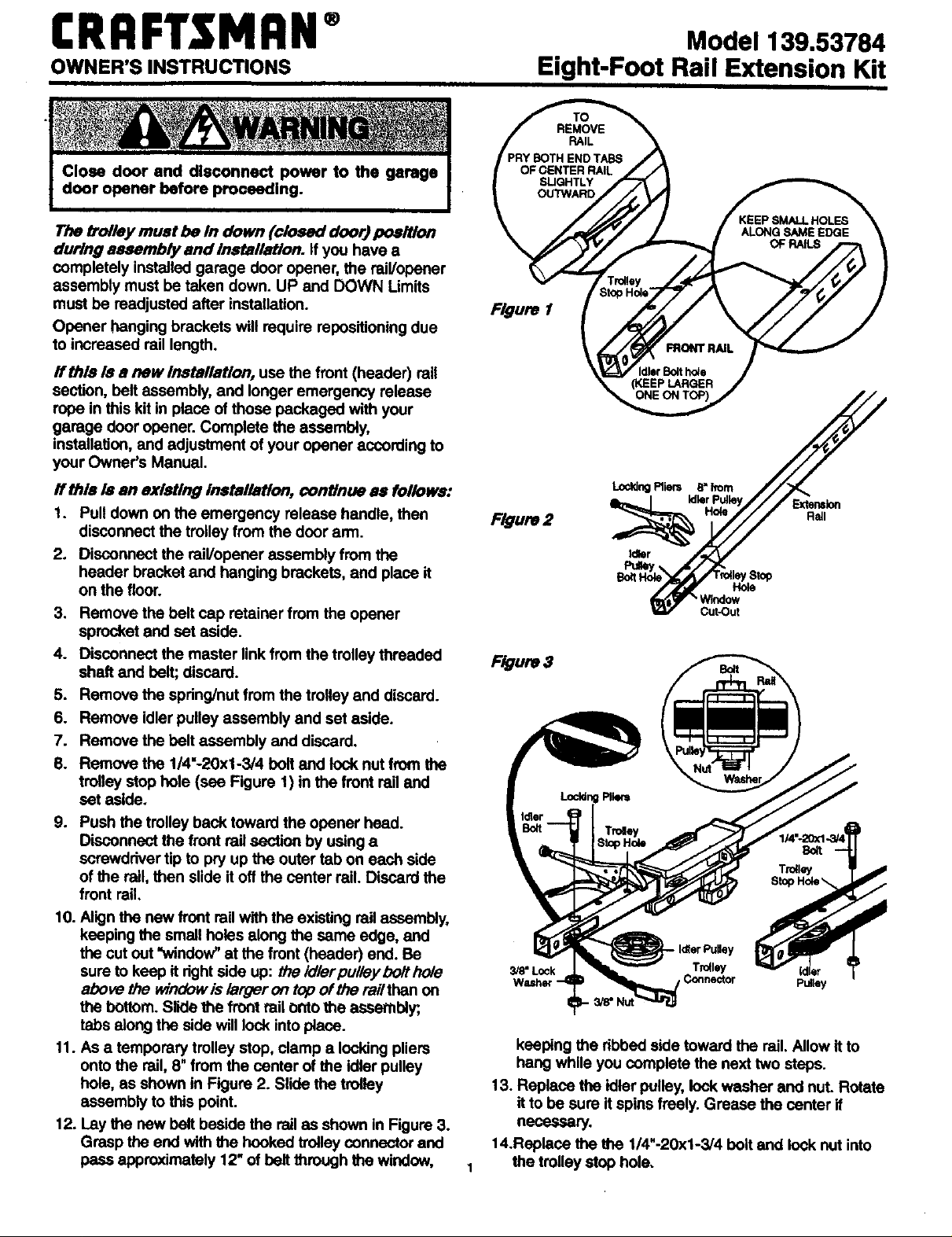
8. Remove the 1/4"-20xl-3/4 bolt and lock nut from the
trolley stop hole (see Figure 1) in the front rail and
set aside.
9. Push the trolley back toward the opener head.
Disconnect the front rail section by using a
screwdriver tip to pry up the outer tab on each side
of the rail, then slide it off the center rail. Discard the
front rail.
10. Align the new front rail with the existing railassembly,
keeping the small holes along the same edge, and
the cut out =window" at the front (header) end. Be
sure to keep it right side up: the idler pulley bolt hole
above the _dndow is /arger on top of the rail than on
the bottom. Slide the front rail onto the assembly;
tabs along the side will lock into place.
11. As a temporary trolley stop, clamp a locking pliers
onto the rail, 8" from the center of the idler pulley
hole, as shown in Figure 2. Slide the trolley
assembly to this point.
12. Lay the new belt beside the rail as shown in Figure 3.
Grasp the end with the hooked trolley connector and
pass approximately 12"of belt through the window,
Model 139.53784
Eight-Foot Rail Extension Kit
Figure 1
F_ure2
Hole
NIndow
Cut-Out
F_ure3
3/8"Lock Tro41ey (dl_
Connector p_y
keeping the dbbed side toward the rail. Allow it to
hang while you complete the next two steps.
13. Replace the idler pulley, lockwasher and nut. Rotate
it to be sure itspins freely. Grease the center if
necessary.
14.Replace the the 1/4"-20xl-3/4 boltand lock nut into
the trolley stop hole.
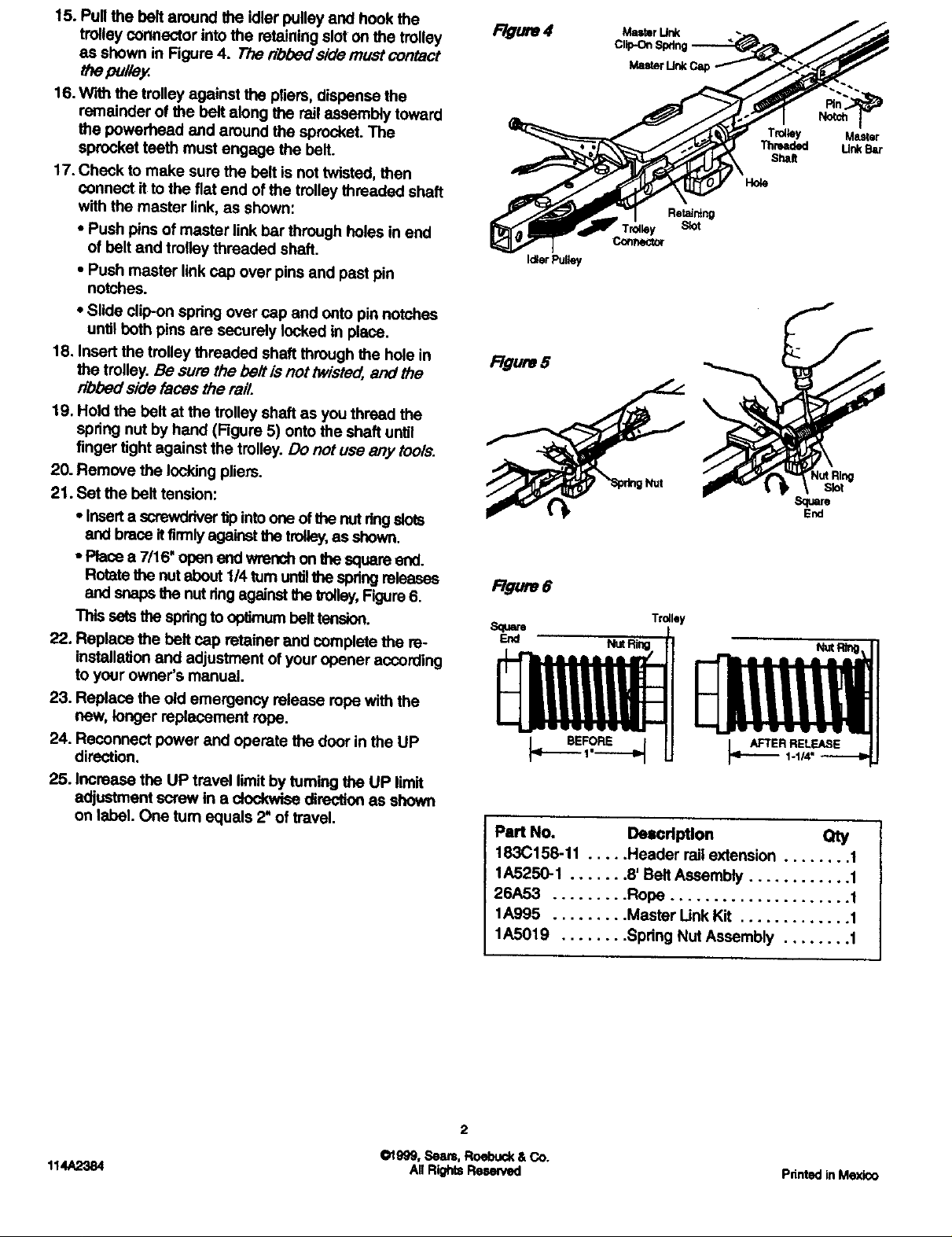
15. Pull the belt around the idler pulley and hook the
trolley connector into the retaining slot on the trolley
as shown in Figure 4. The dbbed side must contact
_e pu/fay.
16. With the trolley against the pliers, dispense the
remainder of the belt along the rail assembly toward
the powerhead end around the sprocket. The
sprocket teeth must engage the belt.
17. Check to make sure the belt is not twisted, then
connect it to the fiat end of the trolley threaded shaft
with the master link, as shown:
• Push pins of master link bar through holes in end
of belt and trolley threaded shaft.
• Push master link cap over pins and past pin
notches.
• Slide clip-on spring over csp and onto pin notches
until both pins are securely locked in place.
18. Insert the trolley threaded shaft through the hole in
the trolley. Be sure the be# is not lwisted, and the
dbbed side faces the rail.
19. Hold the belt at the trolley shaft as you thread the
spring nut by hand (Figure 5) onto the shaft until
finger tight against the trolley. Do not use any tools.
20. Remove the locking pliers.
21. Set the belt tension:
• Inserta screwdriver tipintoone of the nut dng slots
sr_l brace It firmly agak_stthe trolley,as shown.
- Place a 7/16' open end wrench on the square end.
Rotate the nut about 1/4 turn untilthe spring releases
and ,snapsIhe nut ringagainst file _011ey,Figure6.
This sets the springto optimum belt tension.
22. Replace the belt cap reta'merand complete the re-
installation and adjustment of your opener according
tO your owner's manual.
23. Replace the old emergency release rope with the
new, longer replacement rope.
24. Reconnect power and operate the door in the UP
direction.
25. Increase the UP travel limit by turning the UP limit
adjustment screw in e _ direction as shovm
on label. One turn equals 2" of travel.
Master Unk Ca
Trolley
Threaded
Shah
Ho/e
Id;erPulley
F/gum 5
F/guro 6
Sure
Trdley
NutRtng_
_..___ER RELEASE
%1/4"
Part No. Description
163C158-11 ..... Header railextensiOn ........ t
1A5250-1 ....... 8' Belt Assembly ............ 1
26A53 ......... Rope ..................... 1
1A995 ......... Master llnk Kit ............. 1
1A5019 ........ Spring Nut Assembly ........ 1
2
01999, Seam,Roebuck& Co,
All RightsResewed114A2384 Pdntedin Mexico
 Loading...