

Craftsman 13953920DM Owner’s Manual
Owner's Manual/ManualDel Propietario
CRRFTSMRN°[
1/2 HP
315MHz GARAGEDOOROPENER
ABRIDORDEPUERTADECOCHERADE
ForResidentialUseOnly/S61opara usoresidencial
Model/Modelo• 139.53920DM
_315MHz
I"I'1
z
Readandfollowall safetyrulesand
operatinginstructionsbeforefirstuseof
thisproduct.
Fastenthe manualnearthe garagedoor
afterinstallation.
Periodic checksof theopenerarerequired
to ensuresafeoperation.
Sears, Roebuck and Co., Hoffman Estates, IL 60179 U.S.A
www.sears.com/craftsman
Leeryseguirtodaslasreglasdeseguridad
y lasinstruccionesde operaci6nantesde
usaresteproductoporprimeravez.
Guardarestemanualcercade la puerta de
la cochera.
Se debenrealizarrevisionesperi6dicas del
abridorde puertas para asegurarsu
operaci6n segura.
I'll
"o
z_
0
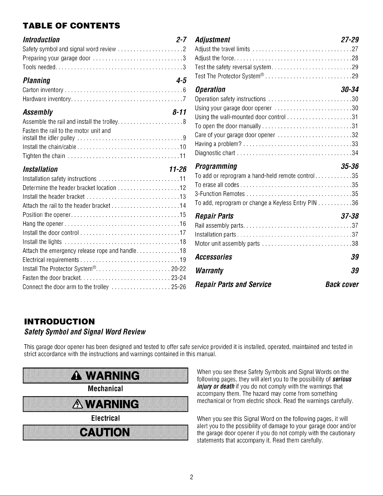
TABLE OF CONTENTS
Introduction 2-7
Safetysymbol andsignal word review ..................... 2
Preparingyour garagedoor ............................. 3
Tools needed......................................... 3
Planning 4-5
Carton inventory ...................................... 6
Hardware inventory.................................... 7
Assembly 8-11
Assemblethe railand install thetrolley ..................... 8
Fastenthe railto the motor unit and
install the idler pulley .................................. 9
Install the chain/cable................................. 10
Tighten the chain .................................... 11
Installation 11-26
Installation safetyinstructions .......................... 11
Determinethe headerbracket location .................... 12
Install the headerbracket .............................. 13
Attachthe rail to the headerbracket ...................... 14
Position theopener................................... 15
Hangthe opener..................................... 16
Install the door control ................................ 17
Install the lights ..................................... 18
Attachthe emergency releaseropeand handle.............. 18
Electricalrequirements ................................ 19
Install The Protector System®........................ 20-22
Fastenthe door bracket............................. 23-24
Connectthe door arm to the trolley ................... 25-26
Adjustment 27-29
Adjust thetravel limits ................................ 27
Adjust theforce...................................... 28
Testthe safety reversalsystem.......................... 29
TestThe Protector System®............................ 29
Operation 30-34
Operationsafety instructions ........................... 30
Usingyour garagedoor opener ......................... 30
Usingthe wall-mounted door control ..................... 31
To open thedoor manually............................. 31
Careof your garagedoor opener ........................ 32
Havinga problem? ................................... 33
Diagnosticchart ..................................... 34
Programming 35-36
To add or reprogram ahand-heldremotecontrol ............ 35
To erase all codes.................................... 35
3-Function Remotes.................................. 35
To add, reprogram or change a KeylessEntry PIN ........... 36
Repair Parts 37-38
Railassembly parts................................... 37
Installation parts ..................................... 37
Motor unit assembly parts ............................. 38
Accessories 39
Warranty
RepairPartsandService
Back cover
39
INTRODUCTION
SafetySymbolandSignalWordReview
This garage door opener has beendesigned and testedto offer safe serviceprovided it is installed,operated, maintained andtested in
strict accordancewith the instructions and warnings containedinthis manual.
Whenyou seethese Safety Symbols andSignal Words on the
following pages,they will alert you to the possibility of serious
Mechanical
Electrical
injury or deathif you do not comply with the warnings that
accompanythem. Thehazardmay comefrom something
mechanicalor from electric shock.Readthe warnings carefully.
Whenyou seethis SignalWord on thefollowing pages,it will
alertyou to the possibility of damageto your garagedoor and/or
the garage dooropener if you do not comply with the cautionary
statementsthat accompanyit. Readthem carefully.

Preparingyourgaragedoor
Beforeyou begin:
• Disablelocks.
• Removeany ropesconnectedto garagedoor.
• Completethe followingtestto makesureyour garagedoor is
balancedand isnot sticking or binding:
1. Lift the door abouthalfwayas shown. Releasethe door.
If balanced, it should stay in place,supported entirely by its
springs.
2. Raiseand lowerthe door to seeif there is any binding or
sticking.
If your door binds, sticks, or is out of balance,call a trained door
systems technician.
To prevent possibleSERIOUSINJURYor DEATH:
• ALWAYScall atrained door systems technician if garagedoor
binds, sticks,or is out of balance.Anunbalancedgaragedoor
may NOTreversewhen required.
• NEVERtry to loosen, move or adjust garagedoor, door
springs, cables, pulleys,brackets or their hardware,ALLof
which areunderEXTREMEtension.
• DisableALL locksand removeALL ropesconnectedto garage
door BEFOREinstalling and operatinggaragedoor openerto
avoid entanglement.
To preventdamageto garagedoorandopener:
• ALWAYSdisable locks BEFOREinstalling andoperating the
opener.
• ONLYoperate garage door opener at 120V,60 Hzto avoid
malfunction anddamage.
SectionalDoor
One-Piece Door
Drill
Tape Measure
Drill Bits_
3/16", 5/16"
and 5/32"
Toolsneeded
During assembly, installation and adjustment of the opener,
instructions will call for hand tools as illustrated below.
Pencil
Hack Saw
Claw Hammer
Wire Cutters
Stepladder
0
Pliers
Screwdriver
Adjustable EndWrench
P_nnmg
Identify the typeand height of your garagedoor. Surveyyour
garageareato see if anyof the conditions below applyto your
installation. Additional materials may be required.You mayfind it
helpfulto refer backto this pageandthe accompanying
illustrations asyou proceedwith the installation ofyour opener.
Dependingon your requirements,there areseveralinstallation
steps which may call for materialsor hardwarenot included in the
carton.
• Installation Step 1- Look at the wall or ceiling abovethe garage
door. Theheaderbracketmust besecurelyfastenedto
structural supports.
• Installation Step 5- Do you have afinished ceiling in your
garage? If so,a support bracketand additional fastening
hardwaremay berequired.
• Installation Step 10- Dependingupon garageconstruction,
extension bracketsor wood blocks may be neededto install
sensors.
• Installation Step 10- Alternate floor mounting of the safety
reversing sensorwill require hardware not provided.
Doyou havean accessdoor in addition to the garagedoor?
If not, Model 53702 EmergencyKeyReleaseis required.See
Accessoriespage.
Look at the garagedoor where it meetsthe floor. Any gap
betweenthefloor andthe bottom of the door must not exceed
1/4" (6 mm). Otherwise,the safety reversalsystem maynot
work properly.SeeAdjustment Step3. Floor or door should be
repaired.
SECTIONALDOORINSTALLATIONS
• Doyou havea steel, aluminum, fiberglass orglass paneldoor?
If so,horizontal andvertical reinforcement is required
(Installation Step11).
• Theopenershould be installed abovethe centerof the door.
If there isa torsion spring or center bearing platein theway of
the headerbracket,it may be installed within 4 feet (1.22 m) to
the left or right of the door center.SeeInstallation Steps1
and 11.
• If your door is more than 7 feet (2.13 m) high,see rail extension
kits listed on Accessories page.
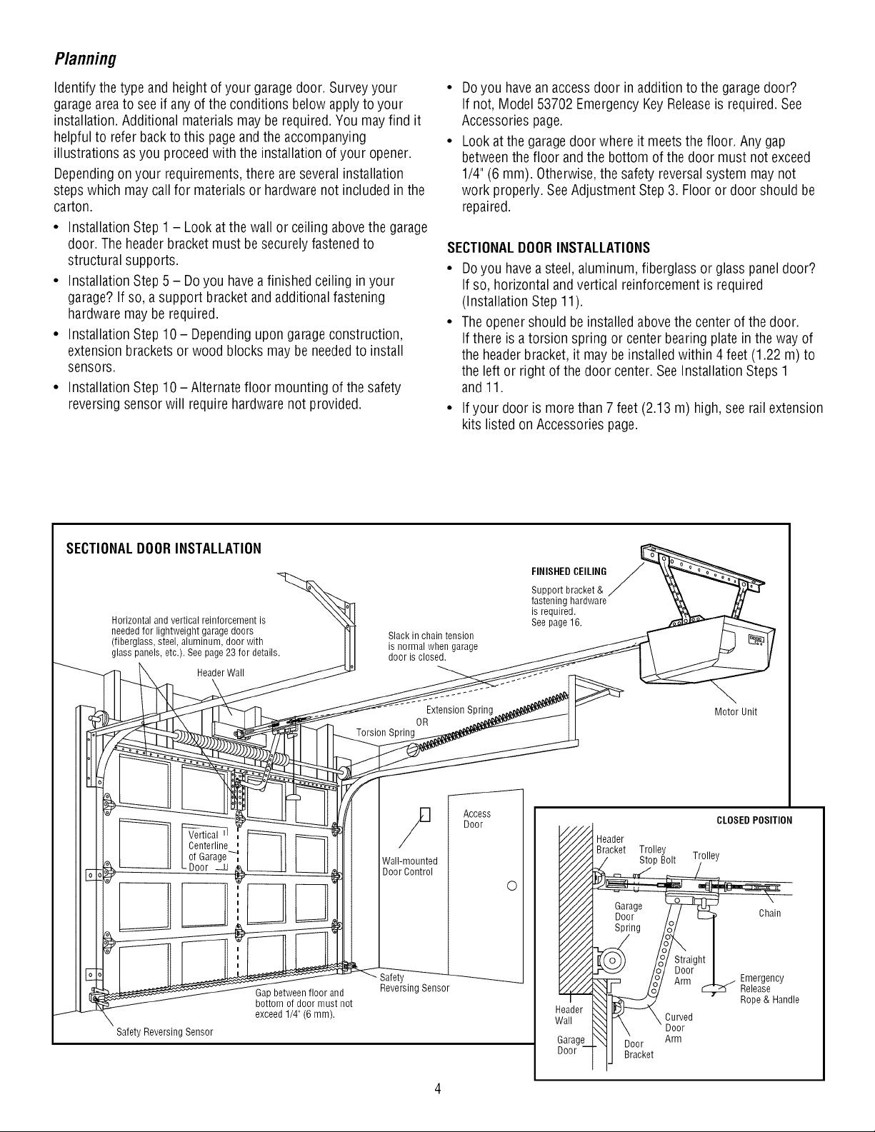
SECTIONALDOORINSTALLATION
Horizontal and vertical reinforcement is
neededfor lightweight garage doors
(fiberglass, steel,aluminum, door with
glass panels, etc.). See page 23for details.
HeaderWall
Centerline
of Garage_
Door _z_
Gapbetween floor and
bottom of door must not
exceed 1/4" (6 mm).
Safety Reversing Sensor
Slack in chain tension
is normal when garage
door is closed.
Torsion Spring
Wall-mounted
Door Control
Safety
Reversing Sensor
Extension Spring
OR
Access
Door
FINISHEDCEILING
Support bracket&
fastening hardware
is required.
See page16.
O
Motor Unit
CLOSEDPOSITION
Header
Bracket Trolle
Garage
Door- /_/ E_ unam
I
ht_
_J Arm | j Emergency
__ Rope&Handle
\_1 P_ \ Curved
HI \ ' Door
__1 I_oor Arm
i
,_o°j/ _ .... _ ReleaSe..
ij Bracket
Planning(Continued)
ONE-PIECEDOORINSTALLATIONS
• Generally,a one-piece door does not requirereinforcement. If
your door is lightweight, refer to the information relatingto
sectional doors in Installation Step11.
• Dependingon your door's construction, you mayneed
additional mounting hardwarefor the door bracket (Step 11).
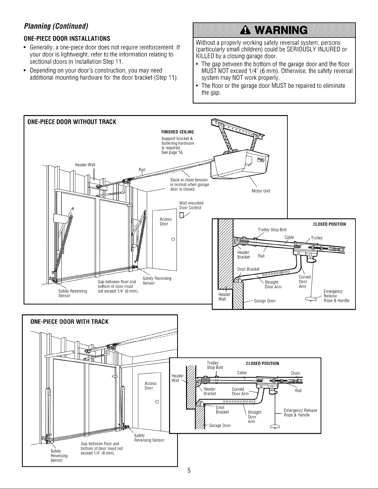
ONE-PIECEDOORWITHOUTTRACK
EINIS,EDCEILINO '&__
Support bracket& _
fastening hardware _
is required. _
See page 16. _ _.,_,_,_r /_,
_ Header Wall //I \ _ II
II1Ill I _ is_i_l_i_e;si_; e X
_ _ [_ ............. Motorunit
IIII o I _11 I _ _Wo1';_°_tnrtold
Without a properly working safetyreversalsystem, persons
(particularly small children) could be SERIOUSLYINJUREDor
KILLEDby a closing garagedoor.
• Thegap betweenthe bottom of the garagedoor and the floor
MUSTNOTexceed1/4"(6 mm). Otherwise,the safetyreversal
system may NOTwork properly.
• Thefloor orthe garagedoor MUSTberepairedto eliminate
the gap.
_ I II_iII I _oor I_ CLOSEDPOS,T,O.
IIIdl_ I Ill'Ill I I V/./_I T_,,eystopBo,t
• I IIIII_l I I o I V/./ _ Cab,eTro,,oy
oii,m!!!!
Sensor le
Trolley
Stop Bolt
_,, Cab!e L
_eader Curved_ W_
Bracket D00rArm7 / i._
_ ooooooooooo_J
p_- Door \
//_.._ Bracket \ Straight
////_ Door
//".-! Arm
Y_'/-_-Garage Door
CLOSEDPOSITION
Chain
) Rail
EmergencyRelease
-- Rope & Handle
I __ Safety. I
._J. _ 14_ GoatPtbetoWfe_nH f'^..oor°l_lru_dnot Reversing Sensor I
SaefveertYing exceed 1/4" (6 mnl). I
Sensor J
5
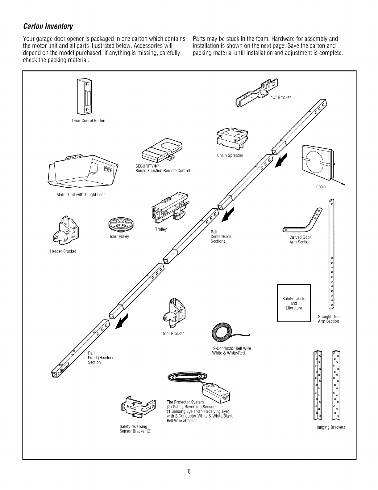
CartonInventory
Your garage door opener is packagedin onecarton which contains
the motor unit and allparts illustrated below.Accessorieswill
dependon the model purchased.If anything is missing, carefully
checkthe packingmaterial.
Door Conrol Button
SECURITY÷®
Single-Function Remote Control
Motor Unit with 1 Light Lens
Parts may be stuck in the foam. Hardwarefor assembly and
installation isshown onthe next page.Savethe carton and
packing material until installation andadjustment is complete.
Chain Spreader
Chain
Header Bracket
Rail
Front (Header)
Section
Idler Pulley
Safety reversing
Sensor Bracket (2)
Trolley
Door Bracket
The Protector Systerr_ _
(2) Safety Reversing Sensors
(1 Sending Eyeand 1 Receiving Eye)
with 2-Conductor White & White/Black
Bell Wire attached
Rail
Center/Back
Sections
2-Conductor BellWire
White & White/Red
Curved Door
Arm Section
Safety Labels
and
Literature
_'1
J
Straight Door
Arm Section
I,
1,
%
I.
%
_1°
Hanging Brackets

HardwareInventory
Separateall hardwareandgroup asshown below for the assembly and installation procedures.
ASSEMBLYHARDWARE
Lock Nut Washer 5/8" (2) Lock Washer Nut
1/4"-20 (2) 3/8" (1) 3/8" (1)
Bolt 1/4"-20xl-3/4" (1)
1
0
Bolt 1/4"-20x2-1/2 (1)
[o
)lii;)l)))i!))l!_)
Spacer (2)
Trolley Threaded Shaft (1)
i
Master
Link (2)
Idler Bolt(l)
Carriage Bolt
1/4"-20xl/2" (2)
Lag Screw
5/16"-9xl-5/8" (2)
111111111111_>
Lag Screw
5/16"-18xl-7/8" (2)
_ng Screw
1/4"-14x5/8" (2)
Wing Nut
1/4"-20 (2)
INSTALLATIONHARDWARE
© %
Ring Nut 5/16"-18 (6)
Fastener (3)
_llllllllll) _:_
Hex Bolt
5/16"-18x7/8" (4) Lock Washer 5/16" (5)
_lllllllllllllllllllllllll}
Screw
6ABx1-1/4" (2)
iiii_;i -h
III/HI
Drywall Anchors (2)
_ ifiii-fiiiiNfiiifii]iiiiii fiii';:>
Screw 6ABxl-1/2"
Lighted Door Control Button
Handle
Insulated
Staples (30)
111111111111111111111
Screw 6-32xl" (2)
Rope
ol
Clevis Pin Clevis Pin Clevis Pin
5/16"x1-1/2" (1) 5/16"x1" (1) 5/16"x1-1/4" (1)
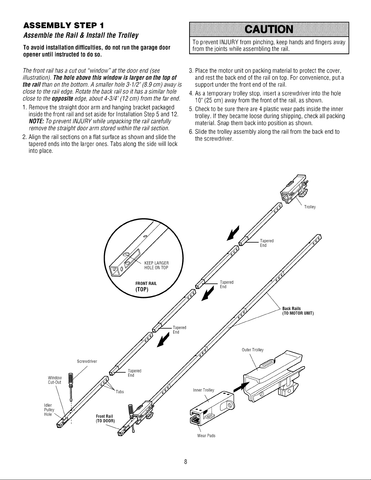
ASSEMBLY STEP 1
Assemble the Rail & Install the Trolley
To avoidinstallationdifficulties,donotrunthe garagedoor
openeruntil instructedtodo so.
To prevent INJURYfrom pinching, keephandsand fingers away
from thejoints while assemblingthe rail.
Thefront rafthas a cut out "window" at the door end (see
illustration). Theholeabovethis windowis larger onthe topof
the rail than on the bottom. Asmaller hole3-1/2" (8.9 cm) away is
close to therail edge.Rotatethe back rail soit hasasimilar hole
close to theoppositeedge,about 4-3/4" (12 cm) from the far end.
1. Removethe straight door arm andhangingbracket packaged
insidethe front rail and set aside for Installation Step 5and 12.
NOTE:Toprevent INJURYwhileunpacking therail carefully
removethe straight doorarm stored within the rail section.
2. Align the railsectionson aflat surface asshown and slidethe
taperedends into the largerones.Tabs along the sidewill lock
into place.
3. Placethe motor unit on packing materialto protect the cover,
and rest the backendof the rail on top. Forconvenience,put a
support underthe front end of the rail.
4.As atemporary trolley stop, insert ascrewdriver into the hole
10"(25 cm) awayfrom the front of the rail, asshown.
5. Checkto besure there are4 plasticwear pads insidethe inner
trolley. If they became loose during shipping, checkall packing
material.Snap themback into position asshown.
6. Slidethe trolley assembly along the railfrom the backendto
the screwdriver.
Trolley
)ered
End
Window
Cut-Out
Idler
Pulley
Hole
Screwdriver
FrontRail
(TO DOOR)
Tapered
End
End
Tapered
End
)ered
Inner Trolley __
Wear Pads
BackRails
(TO MOTORUNIT)
OuterTrolley
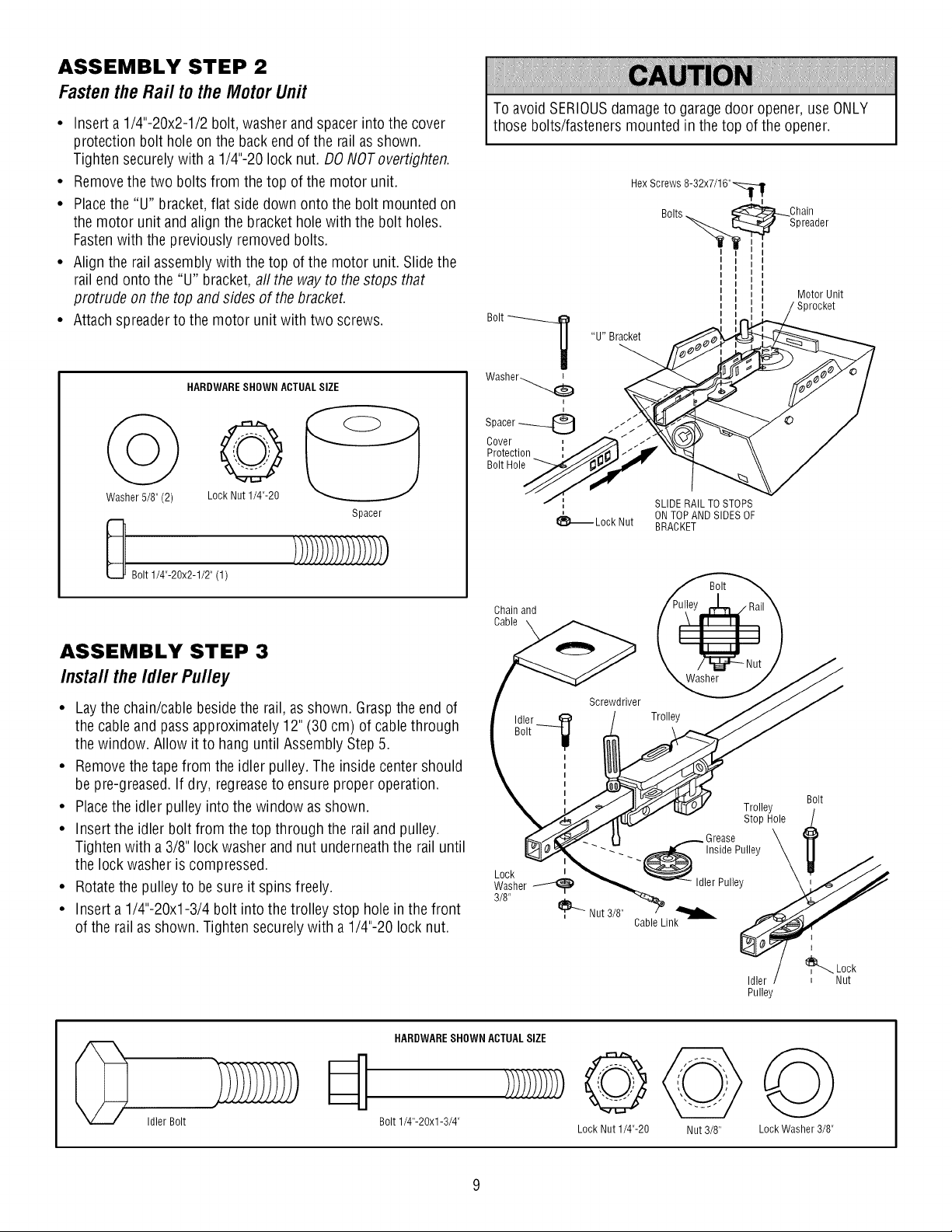
ASSEMBLY STEP 2
FastentheRail to theMotorUnit
• Inserta1/4"-20x2-1/2 bolt, washerandspacerintothe cover
protection bolt holeon the backendof the railasshown.
Tighten securelywith a 1/4"-20 locknut. DONOToverfighten.
• Removethe two bolts from the top of the motor unit.
• Placethe "U" bracket,flat side down onto the bolt mountedon
the motor unit and alignthe brackethole with the bolt holes.
Fastenwith the previously removed bolts.
• Align the rail assemblywith thetop of the motor unit. Slide the
rail end onto the "U" bracket, all the way to thestops that
protrude on the top and sides of thebracket.
• Attachspreader to the motor unit with two screws.
To avoid SERIOUSdamageto garagedoor opener,use ONLY
those bolts/fastenersmounted in the top of theopener.
Hex Screws 8-32x7/16"_,
Bolts_ _ _L_Ohain
-____. [::_:._ Spreader
I
Motor Unit
Sprocket
"U" Bracket
Bolt___
HARDWARESHOWN ACTUALSIZE
o@
Washer 5/8" (2)
Bolt 1/4"-20x2-1/2" (1)
ASSEMBLY STEP 3
Installthe IdlerPulley
• Laythe chain/cablebesidethe rail, as shown. Graspthe endof
the cable and pass approximately 12" (30 cm) of cable through
the window. Allow it to hanguntil Assembly Step 5.
• Removethe tape from the idler pulley.The inside centershould
be pre-greased. If dry, regreaseto ensureproper operation.
• Placethe idler pulleyinto the window as shown.
• Insertthe idler bolt from the top through the railandpulley.
Tighten with a3/8" lock washer and nut underneaththe rail until
the lock washer is compressed.
• Rotatethe pulley to besure it spins freely.
• Inserta 1/4"-20xl-3/4 bolt into the trolley stop holeinthe front
of the railasshown. Tightensecurelywith a 1/4"-20 lock nut.
LockNut1/4"-20
Spacer
Washer_
i
Spacer_
Cover
Protection
Bolt Hole
SLIDE RAIL TOSTOPS
1_ Lock Nut BRACKET
Chain and
Cable
Screwdriver
WasherL°Ck_ _ Idler Pulley
3/8" _, Nut 3/8"
ONTOPAND SIDES OF
Washer
Trolley
Grease
_ _ _ _ -Inside Pulley
Cable Link
Trolley
Stop Hole
Bolt
Idler Bolt
HARDWARESHOWN ACTUALSIZE
Bolt 1/4"-20xl-3/4"
@
Lock Nut 1/4"-20
Nut 3/8"
Idler
Pulley
Lock Washer 3/8"
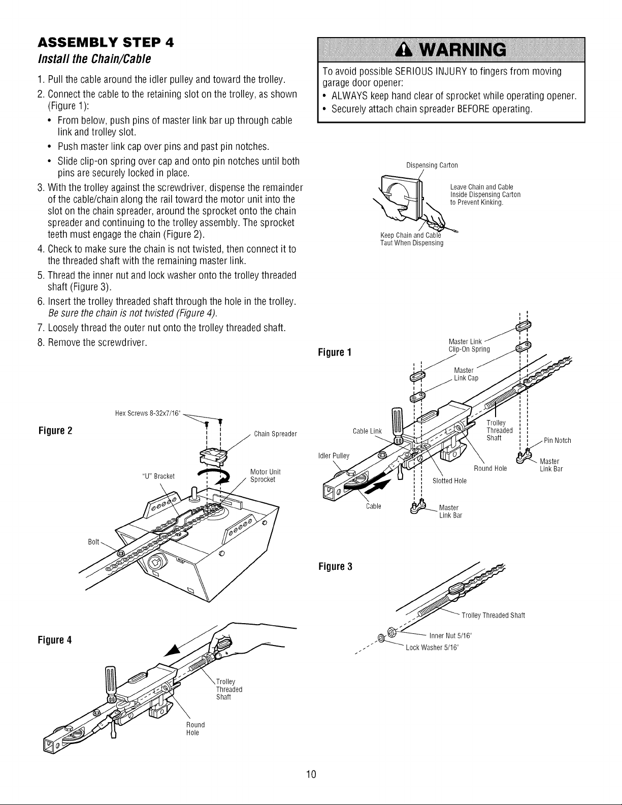
ASSEMBLY STEP 4
Install the Chain/Cable
1. Pull thecablearound the idler pulleyand toward the trolley.
2. Connectthe cableto the retainingslot on the trolley, asshown
(Figure1):
• From below, push pins of masterlink bar up through cable
link and trolley slot.
• Pushmaster link cap over pinsand pastpin notches.
• Slide clip-on spring over capandonto pin notches until both
pins aresecurely locked in place.
3. With thetrolley againstthe screwdriver, dispensethe remainder
of the cable/chainalong the railtoward the motor unit into the
slot onthe chain spreader, around the sprocketonto the chain
spreaderand continuingto thetrolley assembly.Thesprocket
teeth must engagethe chain (Figure2).
4. Checkto makesure the chain is nottwisted, then connect it to
thethreaded shaft with the remainingmaster link.
5. Threadthe inner nut andlock washer onto thetrolley threaded
shaft (Figure 3).
6. Insert thetrolley threadedshaft through the hole in thetrolley.
Be surethe chain is not twisted (Figure 4).
7. Looselythread the outer nut ontothe trolley threadedshaft.
8. Removethe screwdriver.
Figure2
Hex Screws 8-32x7/16"
Chain Spreader
Motor Unit
Sprocket
To avoid possibleSERIOUSINJURYto fingers from moving
garagedoor opener:
• ALWAYSkeephand clearof sprocket while operating opener.
• Securely attachchain spreaderBEFOREoperating.
Dispensing Carton
:_ Leave Chain and Cable
t_Cabl_e to Prevent Kinking.
Taut When Dispensing
FigureI
Inside Dispensing Carton
Master Link
Clip-On Spring
astor
®
I
II
/ II t
Cable Link__.
/_ Threaded : ',
Shaft _ Pin Notch
•" \ _ \ Er'---- Master
\ Round Hole Link Bar
', Slotted Hole
i
Figure4
Round
Hole
Y
Threaded
Shaft
Figure3
10
/
Cable
J
----- Lock Washer 5/16"
t
(_)-_ Master
Link Bar
ASSEMBLY STEP 5
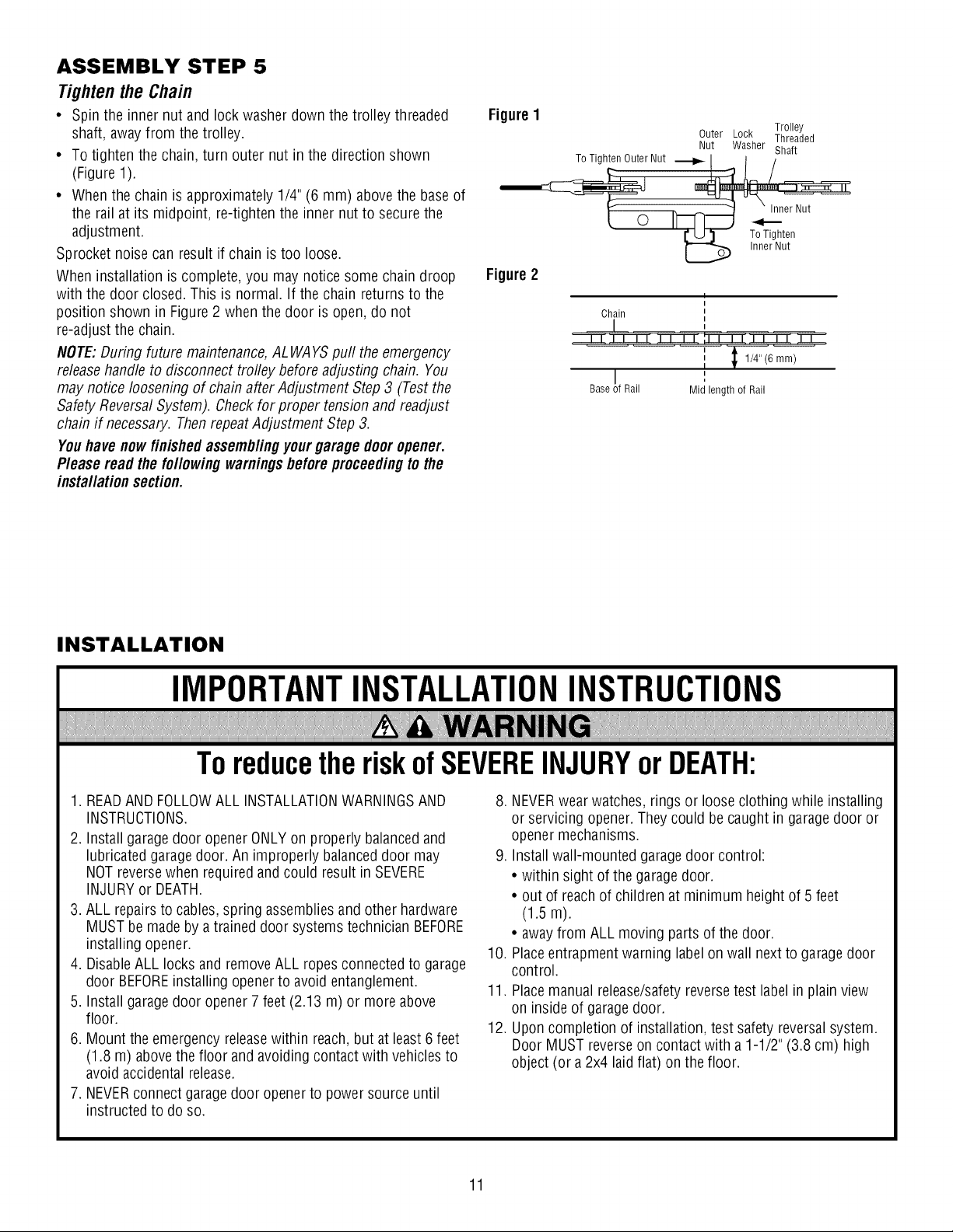
TightentheChain
• Spin the innernut andlockwasher down the trolley threaded
shaft, awayfrom the trolley.
• To tighten the chain,turn outer nut inthe direction shown
(Figure 1).
• Whenthe chain is approximately 1/4" (6 mm) abovethe base of
the rail at its midpoint, re-tightenthe inner nut to securethe
adjustment.
Sprocket noise can result if chain is too loose.
When installation is complete, you may noticesome chaindroop
with the door closed. This is normal. If the chain returns to the
position shown in Figure 2 when the door is open,do not
re-adjust the chain.
NOTE:During future maintenance,ALWAYSpuff the emergency
releasehandle todisconnect trofley beforeadjusting chain. You
may noticeloosening of chainafter Adjustment Step3 (Testthe
Safety ReversalSystem). Checkfor proper tension and readjust
chain if necessary. ThenrepeatAdjustment Step3.
Youhave nowfinishedassemblingyourgarage dooropener.
Please read thefollowingwarningsbeforeproceedingto the
installationsection.
Figure1
Figure2
To Tighten Outer Nut
Chain
Base Rail
Outer Lock Threaded
Nut Washer Shaft
I
Mid length of Rail
Trolley
Inner Nut
To Tighten
Inner Nut
1/4" (6 mm)
INSTALLATION
IMPORTANTINSTALLATIONINSTRUCTIONS
ToreducetheriskofSEVEREINJURYorDEATH:
1. READAND FOLLOWALL INSTALLATIONWARNINGSAND
INSTRUCTIONS.
2. Installgaragedoor openerONLYon properly balancedand
lubricated garage door. Animproperly balanceddoor may
NOTreversewhen requiredand could resultin SEVERE
INJURYor DEATH.
3. ALL repairsto cables, spring assembliesand other hardware
MUSTbe madeby a traineddoor systemstechnician BEFORE
installing opener.
4. DisableALL locks and removeALL ropesconnectedto garage
door BEFOREinstalling openerto avoid entanglement.
5. Install garagedoor opener7 feet (2.13 m) or more above
floor.
6. Mount the emergencyreleasewithin reach,but at least6feet
(1.8 m) abovethefloor and avoiding contactwith vehiclesto
avoid accidental release.
7. NEVERconnect garagedoor openerto power sourceuntil
instructed to do so.
8. NEVERwear watches,rings or looseclothing while installing
or servicing opener.They could be caughtin garagedoor or
opener mechanisms.
9. Installwall-mounted garagedoor control:
• within sight of the garage door.
• out of reachof children at minimum height of 5 feet
(1.5 m).
• awayfrom ALL moving parts of thedoor.
10. Placeentrapmentwarning labelon wall next to garagedoor
control.
11. Placemanual release/safetyreversetest labelin plainview
on inside of garagedoor.
12. Uponcompletion of installation,test safety reversalsystem.
Door MUST reverseon contact with a 1-1/2" (3.8 cm) high
object (or a2x4 laid flat) on the floor.
11
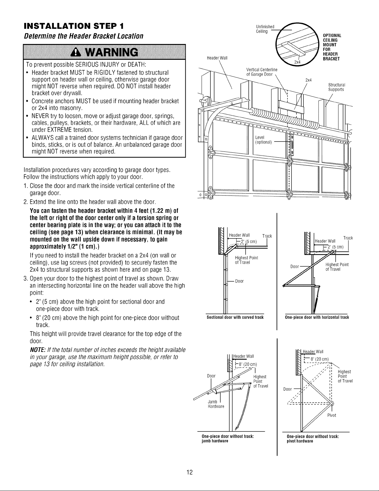
INSTALLATION STEP 1
DeterminetheHeaderBracketLocation
To prevent possibleSERIOUSINJURYor DEATH:
• Headerbracket MUSTbeRIGIDLYfastenedto structural
support on headerwall or ceiling,otherwise garagedoor
might NOTreversewhen required. DONOTinstall header
bracketover drywall.
• Concreteanchors MUST be usedif mounting headerbracket
or 2x4 into masonry.
• NEVERtry to loosen, move or adjust garagedoor, springs,
cables,pulleys, brackets,or their hardware,ALLof which are
under EXTREMEtension.
• ALWAYScall atraineddoor systems technician if garage door
binds, sticks,or is out of balance.Anunbalancedgarage door
might NOTreversewhen required.
Installation proceduresvaryaccording to garagedoor types.
Follow the instructions which applyto your door.
1. Closethe door and mark the insidevertical centerlineof the
garagedoor.
2. Extendthe line onto the headerwall abovethe door.
Youcanfastenthe headerbracketwithin4 feet (1.22 m) of
the left or rightof the doorcenteronlyif atorsionspringor
centerbearingplateis inthe way;or youcanattachit tothe
ceiling(see page13) whenclearance is minimal. (It may be
mountedonthe wall upsidedown if necessary,to gain
approximately1/2"(1 cm).)
If you needto installthe headerbracket ona 2x4 (on wall or
ceiling), uselag screws (not provided) to securelyfastenthe
2x4 to structural supports asshown here and on page 13.
3. Openyour door to the highest point of travelas shown. Draw
an intersecting horizontalline on the headerwall abovethe high
point:
• 2" (5 cm) abovethe high point for sectional door and
one-piecedoor with track.
• 8" (20 cm) abovethe high point for one-piecedoor without
track.
This height will provide travel clearancefor the top edge of the
door.
NOTE:If the totalnumber of inches exceedsthe height available
in your garage,usethe maximum height possible, or refer to
page 13for ceiling installation.
Header Wall
HeaderWall Track
Unifliinnghe_
Vertical Centerline
of GarageDoor
_2_" (.5cm)
<,[ i
HighestPoint
ofTravel
--Door
Sectional door with curved track
HeaderWall
-8" (20cm)
OPTIONAL
CEILING
MOUNT
FOR
HEADER
BRACKET
2x4
Structural
Suppo_s
HeaderWall
"_',_ 2" (5 cm)
_et Point
ofTravel
Y
r
One-piece doorwith horizontal track
Header Wall
Track
Hardware
One-piecedoorwithouttrack:
jambhardware
12
Highest
Point
of Travel
Pivot
One-piece doorwithout track:
pivot hardware
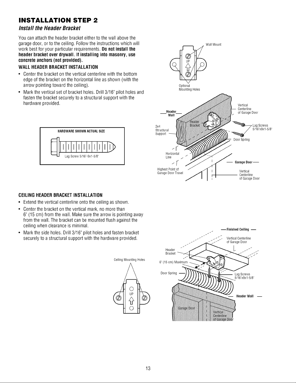
INSTALLATION STEP 2
Installthe HeaderBracket
You can attachthe headerbracketeither to the wallabovethe
garagedoor, or to theceiling. Follow the instructions which will
work bestfor your particular requirements. Do notinstall the
header bracketoverdrywall. If installinginto masonry,use
concreteanchors(notprovided),
WALLHEADERBRACKETINSTALLATION
• Centerthe bracketon thevertical centerlinewith the bottom
edge of thebracketon the horizontal lineasshown (with the
arrow pointing toward the ceiling).
• Mark thevertical setof bracketholes. Drill 3/16" pilot holes and
fastenthe bracketsecurely to astructural support with the
hardware provided.
Optional
MountingHoles
Wall Mount
Vertical
Centerline
of GarageDoor
HARDWARESHOWN ACTUALSIZE
LagScrew 5/16"-9xl-5/8"
CEILINGHEADERBRACKETINSTALLATION
• Extendthe vertical centerline onto the ceiling asshown.
• Centerthe bracketon thevertical mark, no more than
6" (15cm) from the wall. Makesure the arrow is pointing away
from the wall. Thebracketcan bemountedflush againstthe
ceiling when clearanceis minimal.
• Mark theside holes. Drill 3/16" pilot holesand fastenbracket
securelyto a structural support with the hardwareprovided.
Ceiling Mounting Holes
Horizontal
Line / /
-; S
HighestPoint of
Garage DoorTravel
Header
Bracket
6" (15 cm) Maximum
. 5/16"x9x1-5/8"
Door Spring
-- Garage Door--
Vertical
Centerline
of GarageDoor
_Finished Ceiling m
_../_::_ Vertical Centerline
_ of GarageDoor
Lag Screws
13
Door Spring
Lag Screws
5/16"x9x1-5/8"
Header Wall --
Wall
-- Idler Pulley
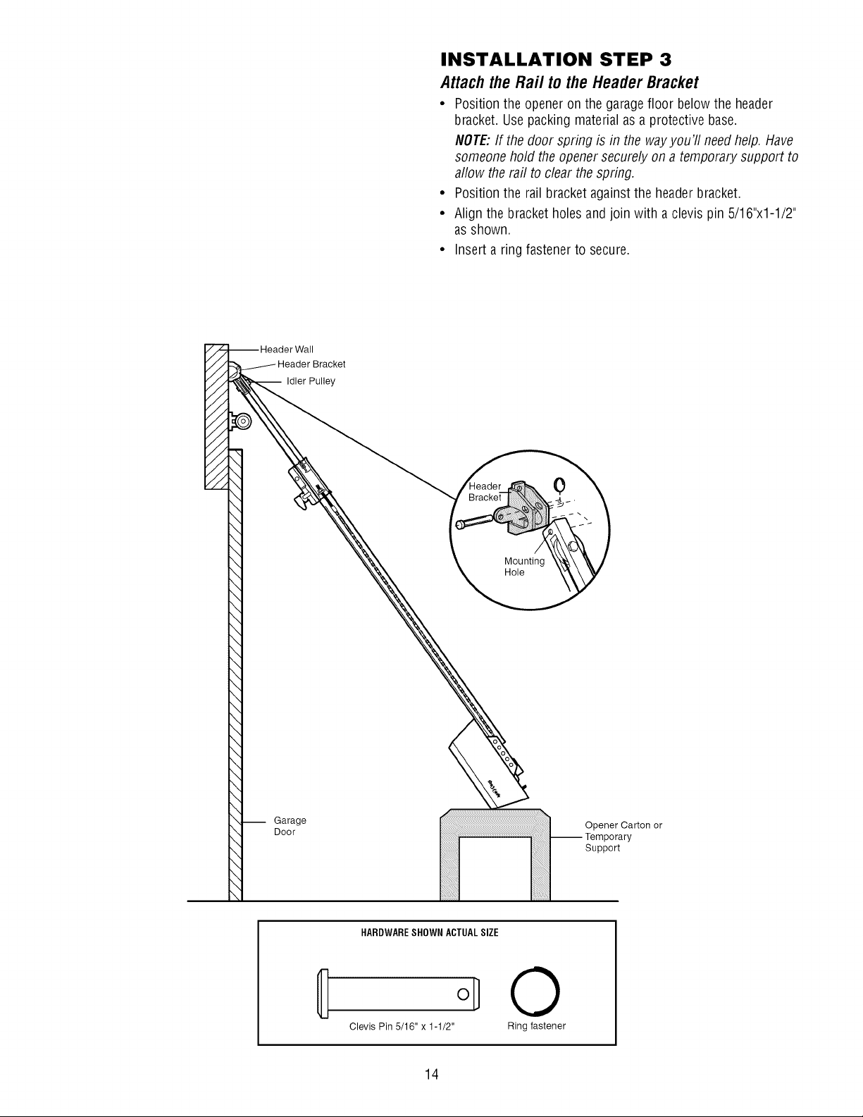
INSTALLATION STEP 3
Attach the Raft to the Header Bracket
• Position the openeron the garagefloor below the header
bracket. Usepacking materialasa protective base.
NOTE:If the door spring is in the wayyou'll need help. Have
someone hold the opener securely ona temporary support to
allow the rail to clear the spring.
• Position the rail bracket againstthe headerbracket.
• Align the bracket holesand join with a clevis pin 5/16"x1-1/2"
as shown.
• Insert a ring fastener to secure.
-- Garage
Door
Mounting
Hole
0
Opener Carton or
-- Temporary
Support
HARDWARESHOWN ACTUALSIZE
Clevis Pin 5/16" x 1-1/2"
14
©
Ring fastener
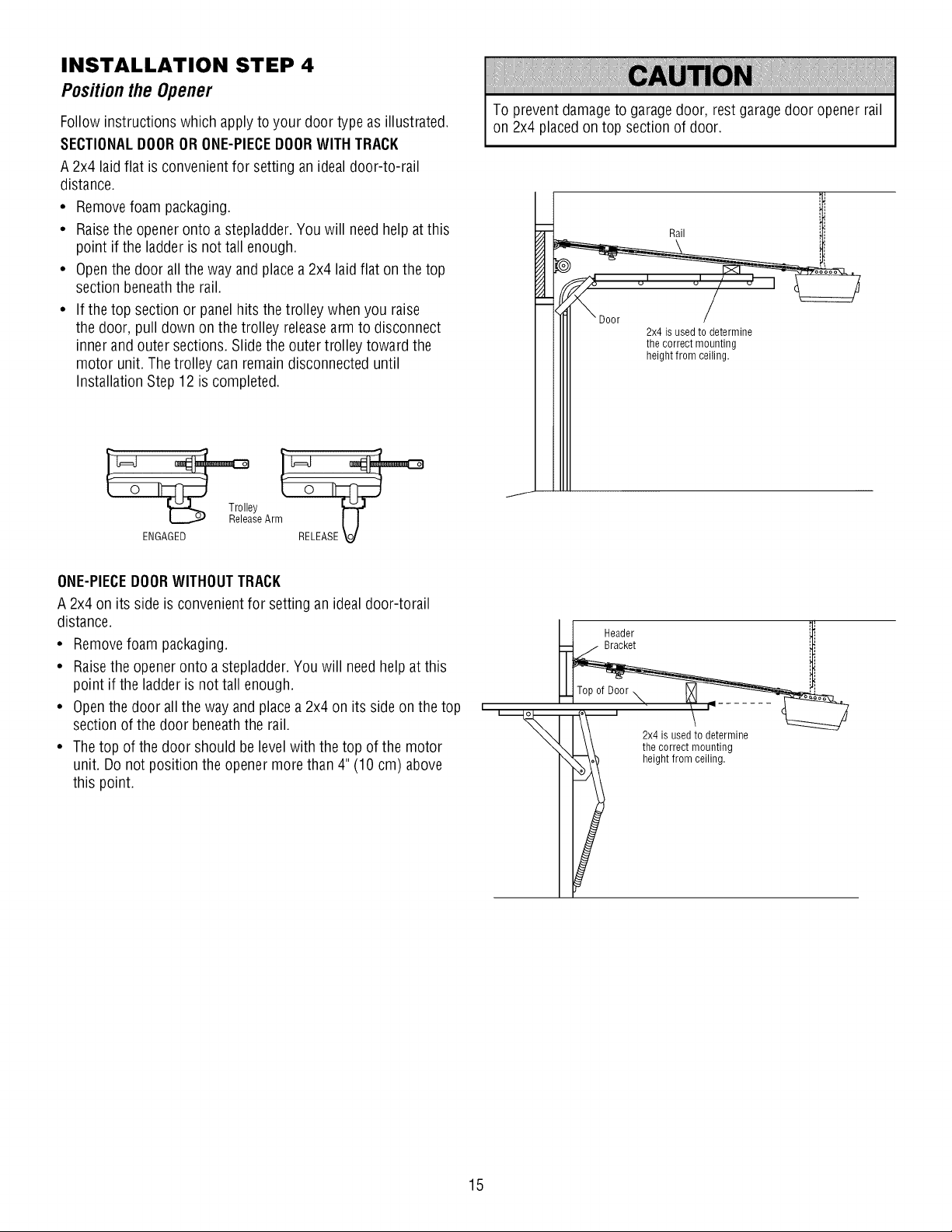
INSTALLATION STEP 4
PositiontheOpener
Follow instructions which applyto your door type as illustrated.
SECTIONALDOORORONE-PIECEDOORWITH TRACK
A 2x4 laid flat is convenientfor setting anidealdoor-to-rail
distance.
• Removefoam packaging.
• Raisethe openeronto astepladder.You will needhelp atthis
point if the ladderis not tall enough.
• Openthedoor allthe wayand placea2x4 laidflat onthe top
section beneaththe rail.
• If the top section or panelhits thetrolley when you raise
the door, pull down on the trolley releasearm to disconnect
inner and outer sections. Slide the outertrolley toward the
motor unit. Thetrolley can remain disconnected until
Installation Step 12is completed.
y }-=€'
seArm [J
ENGAGED RELEASE V
To preventdamageto garagedoor, restgaragedoor openerrail
on 2x4 placedon top section of door.
Rail
2x4 is usedto determine
the correct mounting
height from ceiling.
ONE-PIECEDOORWITHOUTTRACK
A 2x4 on its side is convenientfor setting an ideal door-torail
distance.
• Removefoam packaging.
• Raisethe openeronto a stepladder.Youwill needhelp at this
point if the ladder is not tall enough.
• Openthedoor allthe way andplacea 2x4 on its side on thetop
section of thedoor beneaththe rail.
• Thetop of the door should be levelwith the top of the motor
unit. Do not position theopener more than4"(10 cm) above
this point.
I 1 Header
; 4, used!o2rm, e
i _hegh_r_2,tlln___nnt;n,g
15
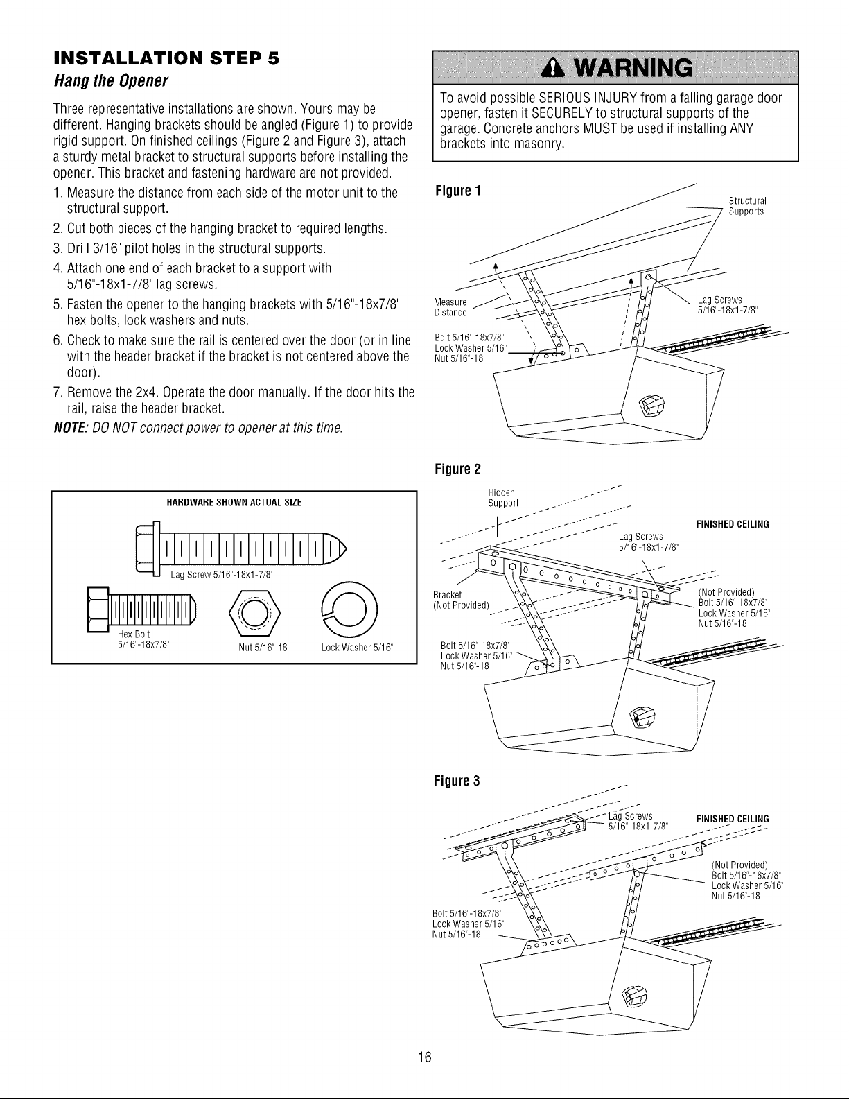
INSTALLATION STEP 5
Hangthe Opener
Threerepresentativeinstallations areshown. Yours may be
different. Hangingbracketsshould beangled(Figure1) to provide
rigid support. On finished ceilings (Figure2 and Figure3), attach
a sturdy metal bracket to structural supports before installing the
opener.This bracketand fastening hardware are not provided.
1. Measurethe distancefrom each sideof the motor unit to the
structural support.
2. Cut both piecesof the hanging bracket to required lengths.
3. Drill 3/16"pilot holesinthe structural supports.
4. Attach oneend of each bracketto a support with
5/16"-18xl-7/8" lagscrews.
5. Fastenthe openerto the hanging brackets with 5/16"-18x7/8"
hex bolts, lock washersand nuts.
6. Checkto makesure the rail is centeredover the door (or in line
with the header bracket if the bracket is not centeredabove the
door).
7. Removethe 2x4. Operatethe door manually. Ifthe door hits the
rail, raise the headerbracket.
NOTE:DONOTconnectpower to openerat this time.
To avoid possible SERIOUSINJURYfrom a falling garagedoor
opener,fasten it SECURELYto structural supports of the
garage.Concrete anchors MUSTbeused if installing ANY
brackets into masonry.
FigureI
Measure Lag Screws
Distance 5/16"-18xl -7/8"
Bolt 5/16"-18x7/8"
Lock Washer 5/16"
Nut 5/16"-18
\
Structural
Supports
HARDWARESHOWN ACTUALSIZE
Lag Screw 5/16"-18xl -7/8"
5/16"-18x7/8" Nut 5/16"-18 Lock Washer 5/16"
Figure2
Hidden _ - _"""
Support _. - _"
_- Lag Screws
Bracket \o_o_ _- (Not Provided)
Not Provided/ _o_o_- _1-cc-J .... _/_ Bolt 5/16"-18x7/8"
- , _- __o_o_T-_ .... /oi,j LockWasher 5/16"
J-=--_ Mo7 Nut 5/16"-18
Bolt 5/16'-18X7/8' _ o__/o/
Figure3
_'_- .-I Lag Screws FINISHEDCEILING
-_ _" _ 5116"-18xl-7/8"
(Not Provided)
Bolt 5/16"-18x7/8"
Lock Washer 5/16"
Nut 5/16"-18
Bolt 5/16"-18x7/8"
Lock Washer 5/16"
Nut 5/16"-18
16
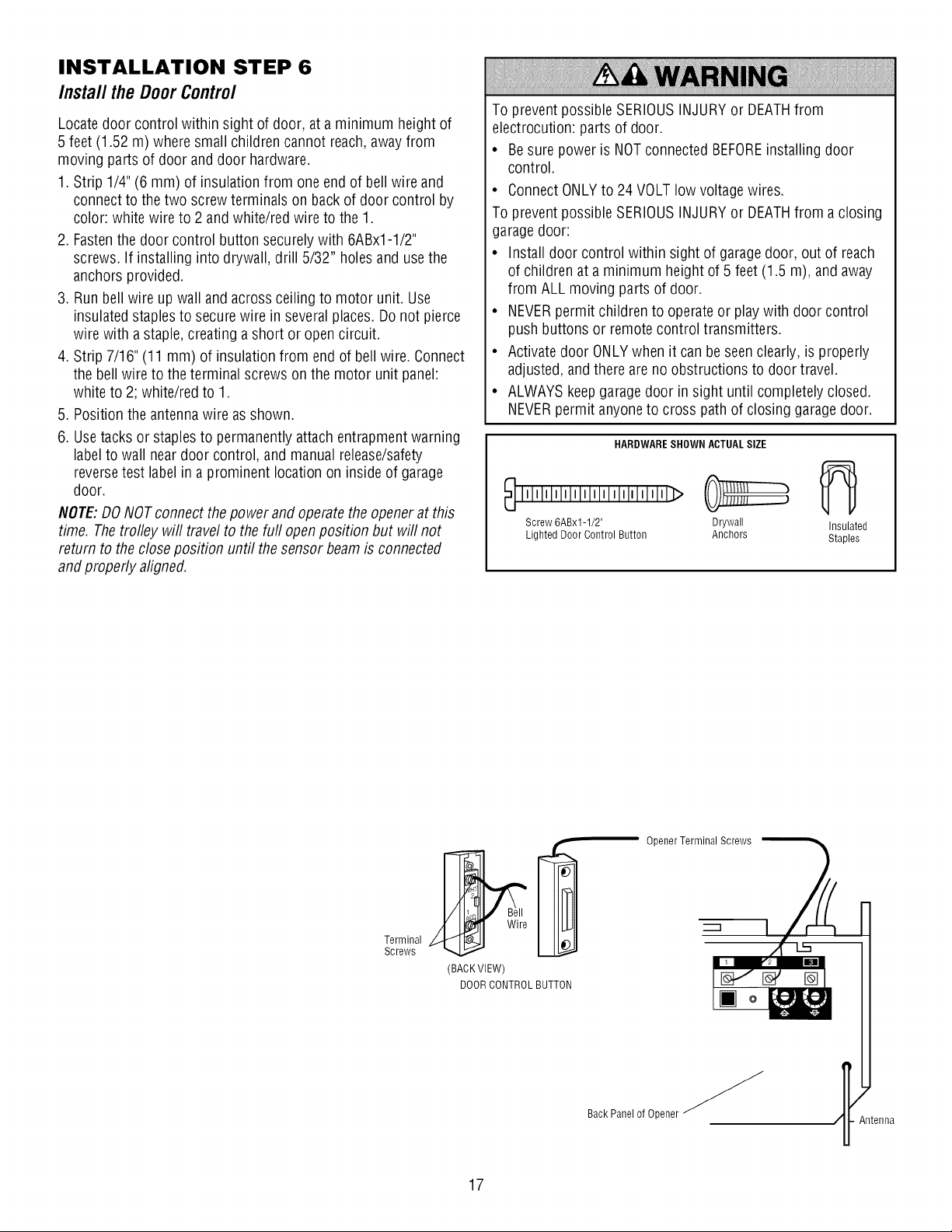
INSTALLATION STEP 6
Install the DoorControl
Locate door control within sight of door, ata minimum heightof
5 feet (1.52 m) where small children cannot reach,away from
moving partsof door anddoor hardware.
1. Strip 1/4"(6 mm) of insulation from one end of bellwire and
connectto thetwo screwterminals on back of door control by
color: whitewire to 2andwhite/red wire to the 1.
2. Fastenthe door control button securelywith 6ABx1-1/2"
screws. If installing into drywall, drill 5/32" holes and usethe
anchors provided.
3. Runbellwire up wall andacrossceiling to motor unit. Use
insulated staplesto securewire in several places. Donot pierce
wire with a staple, creating ashort or opencircuit.
4. Strip 7/16" (11 mm) of insulation from end of bellwire. Connect
the bell wireto the terminal screwsonthe motor unit panel:
white to 2; white/red to 1.
5. Position theantennawire as shown.
6. Usetacks or staplesto permanentlyattach entrapmentwarning
label to wallnear door control, and manualrelease/safety
reversetest labelin a prominent location oninside of garage
door.
NOTE:DONOTconnect thepower and operatethe opener atthis
time. Thetrolley will travel to the furl openposition but will not
return to the closeposition until thesensor beamis connected
and properly aligned.
To prevent possibleSERIOUSINJURYor DEATHfrom
electrocution: parts of door.
• Besure poweris NOTconnected BEFOREinstalling door
control.
• ConnectONLYto 24 VOLT low voltagewires.
To prevent possibleSERIOUSINJURYor DEATHfrom a closing
garage door:
• Install door control within sight of garage door, out of reach
of children at a minimum height of 5 feet (1.5 m), and away
from ALLmoving partsof door.
• NEVERpermit children to operateor playwith door control
pushbuttons or remotecontrol transmitters.
• Activate door ONLYwhen it can beseenclearly, is properly
adjusted, andthere are no obstructions to door travel.
• ALWAYSkeepgaragedoor in sight until completely closed.
NEVERpermit anyoneto cross path of closing garagedoor.
HARDWARESHOWN ACTUALSIZE
Screw 6ABx1-1/2" Drywall Insulated
Lighted Door Control Button Anchors Staples
Terminal
Screws
Opener Terminal Screws
(BACKVIEW)
DOORCONTROLBUTTON
BackPanel of Opener _
Antenna
17
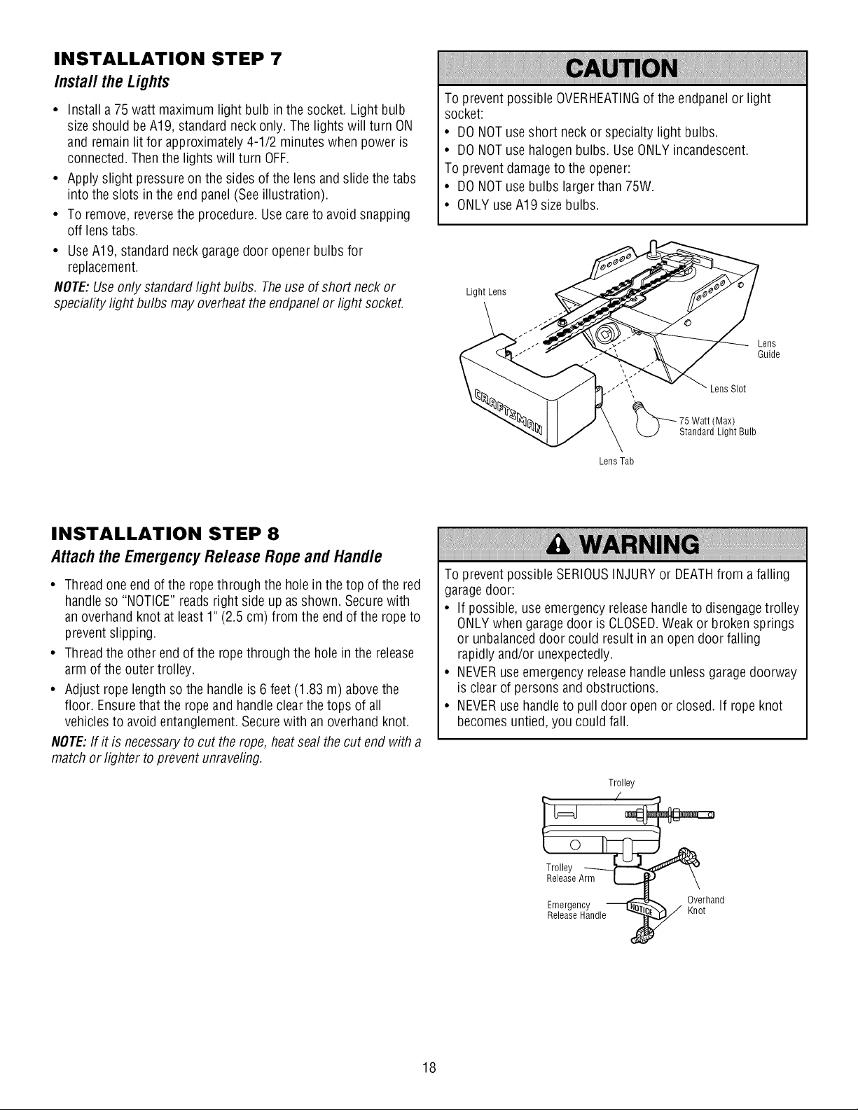
INSTALLATION STEP 7
Install theLights
• Install a 75 watt maximum light bulb inthe socket. Light bulb
size should beA19, standardneckonly.The lights will turn ON
and remainlit for approximately 4-1/2 minutes when power is
connected.Thenthe lights will turn OFF.
• Apply slight pressure on the sidesof the lens and slide the tabs
into the slots in the endpanel (Seeillustration).
• To remove, reversethe procedure. Use careto avoid snapping
off lenstabs.
• UseA19, standardneck garagedoor openerbulbs for
replacement.
NOTE:Use onlystandardlight bulbs. Theuseof short neck or
speciality light bulbs may overheatthe endpanelor light socket.
To prevent possibleOVERHEATINGof the endpanelor light
socket:
• DONOTuseshort neck or specialty light bulbs.
• DONOTusehalogen bulbs. UseONLYincandescent.
To preventdamageto the opener:
• DONOTusebulbs largerthan 75W.
• ONLYuseA19 sizebulbs.
Light Lens
Lens
Guide
Lens Slot
75 Watt (Max)
Standard Light Bulb
Lens Tab
INSTALLATION STEP 8
Attachthe EmergencyRe/easeRopeand Hand/e
• Threadoneendof the ropethrough the holein thetop of the red
handle so "NOTICE"readsright side up asshown. Securewith
an overhandknot at least 1" (2.5 cm) from the endof the rope to
prevent slipping.
• Threadthe other endof the ropethrough the holein the release
arm of the outer trolley.
• Adjust rope length sothe handleis 6feet (1.83 m) abovethe
floor. Ensurethat the ropeand handleclear the tops of all
vehiclesto avoid entanglement.Secure with an overhand knot.
NOTE:If it is necessaryto cut therope, heatsealthe cut endwith a
match or lighter to preventunraveling.
To prevent possibleSERIOUSINJURYor DEATHfrom afalling
garagedoor:
• If possible, useemergencyreleasehandle to disengagetrolley
ONLYwhen garagedoor is CLOSED.Weak or broken springs
or unbalanceddoor could result in an open door falling
rapidly and/or unexpectedly.
• NEVERuseemergency releasehandle unlessgaragedoorway
is clear of persons and obstructions.
• NEVERusehandleto pull door openor closed. If rope knot
becomesuntied, youcould fall.
Trolley
Release Handle Knot
Emergency _ _ Overhand
18
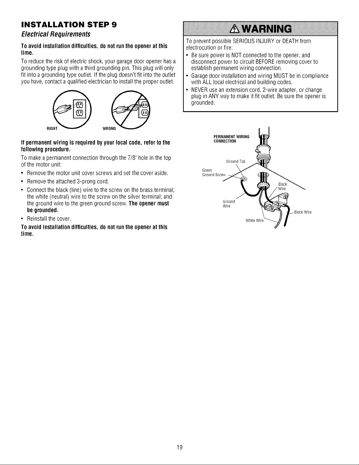
INSTALLATION STEP 9
Electrica/ Requirements
Toavoidinstallationdifficulties,do notruntheopenerat this
time.
To reducethe risk of electricshock, your garagedoor openerhasa
grounding typeplug with athird grounding pin. This plug will only
fit into a grounding type outlet. If the plug doesn'tfit into the outlet
you have,contact a qualifiedelectricianto installthe proper outlet.
If permanent wiring isrequiredby yourlocal code,refertothe
followingprocedure.
Tomake apermanent connection through the 7/8" hole in the top
of the motor unit:
• Removethe motor unit cover screws andset the cover aside.
• Removethe attached3-prong cord.
• Connectthe black(line)wire to the screw on the brass terminal;
thewhite (neutral) wire to the screw on the silverterminal; and
theground wire to the greenground screw. The openermust
begrounded.
• Reinstallthe cover.
Toavoidinstallationdifficulties,do notruntheopenerat this
time.
To prevent possibleSERIOUSINJURYor DEATHfrom
electrocution orfire:
• Besure poweris NOTconnectedto the opener,and
disconnect powerto circuit BEFOREremoving cover to
establish permanentwiring connection.
• Garagedoor installation and wiring MUSTbe in compliance
with ALL localelectricaland building codes.
• NEVERusean extension cord, 2-wire adapter, orchange
plug inANYway to makeit fit outlet. Besurethe openeris
grounded.
PERMANENTWIRING
CONNECTION
Ground Tab
Green
Ground Screw
Ground
Wire
Wire
White Wire
19
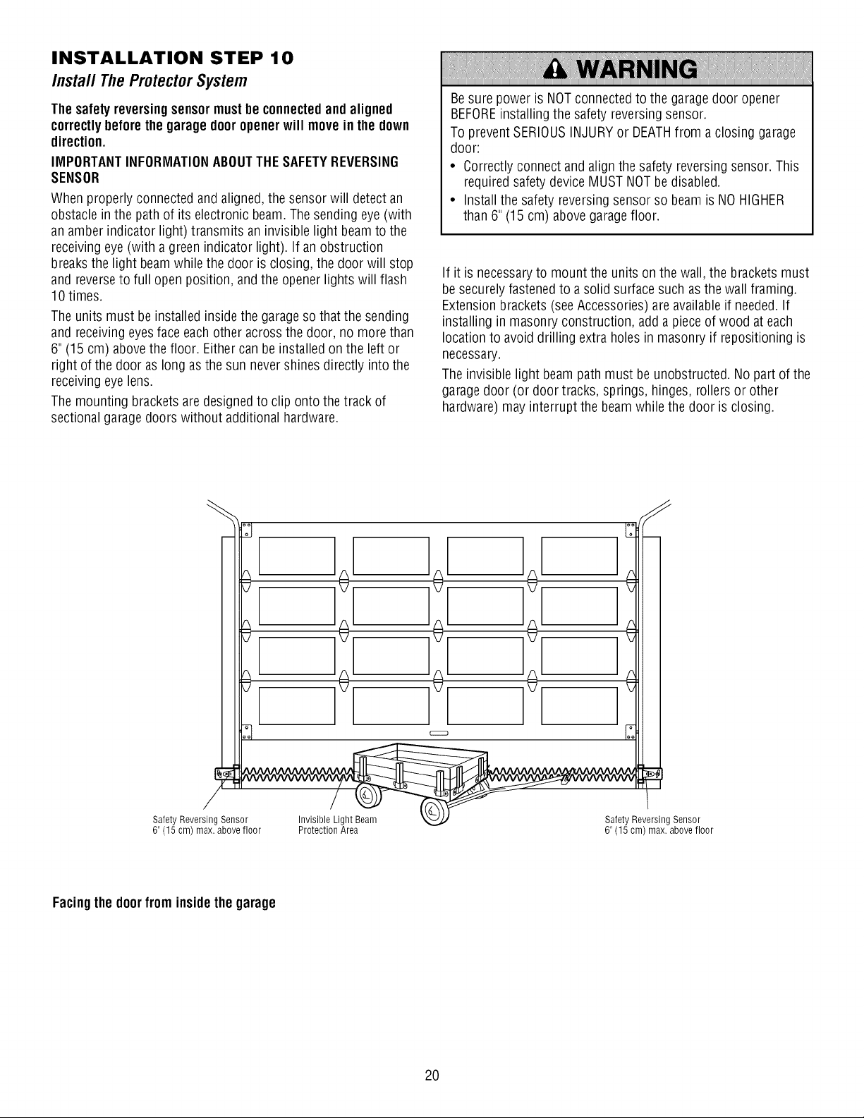
INSTALLATION STEP 10
Install TheProtectorSystem
Thesafety reversingsensormustbeconnectedandaligned
correctlybeforethe garagedooropenerwill movein the down
direction.
IMPORTANTINFORMATIONABOUTTHESAFETYREVERSING
SENSOR
Whenproperly connected andaligned, thesensor will detect an
obstacle in thepathof its electronic beam.Thesending eye (with
an amber indicator light) transmits an invisible light beamto the
receiving eye(with agreen indicator light). If an obstruction
breaksthe light beamwhile the door is closing, the door will stop
and reverseto full open position, andthe openerlights will flash
10 times.
Theunits must beinstalledinsidethe garageso that the sending
and receivingeyesface eachother acrossthe door, no more than
6"(15 cm) abovethe floor. Eithercan be installed onthe left or
right of the door aslong asthe sun nevershines directly into the
receiving eyelens.
Themounting brackets are designedto clip ontothe track of
sectionalgarage doorswithout additional hardware.
Besure poweris NOTconnectedto the garagedoor opener
BEFOREinstalling the safety reversingsensor.
To preventSERIOUSINJURYor DEATHfrom a closing garage
door:
• Correctly connect andalignthe safety reversing sensor. This
requiredsafety device MUSTNOTbedisabled.
• Installthe safety reversingsensor so beam is NOHIGHER
than 6" (15 cm) abovegaragefloor.
If it is necessaryto mount the units on the wall,the bracketsmust
be securelyfastenedto asolid surfacesuch as the wall framing.
Extensionbrackets (seeAccessories) are availableif needed.If
installing in masonry construction, adda pieceof wood at each
location to avoiddrilling extraholes in masonry if repositioning is
necessary.
Theinvisible light beampathmust be unobstructed. No part ofthe
garagedoor (or door tracks, springs, hinges, rollers or other
hardware) may interrupt the beamwhile the door is closing.
/
Safety Reversing Sensor Invisible Light Beam
6" (15 cm) max. above floor Protection Area
Facingthe doorfrom insidethe garage
]o[
]o[
]÷[
Safety Reversing Sensor
6" (15 cm) max. above floor
2O
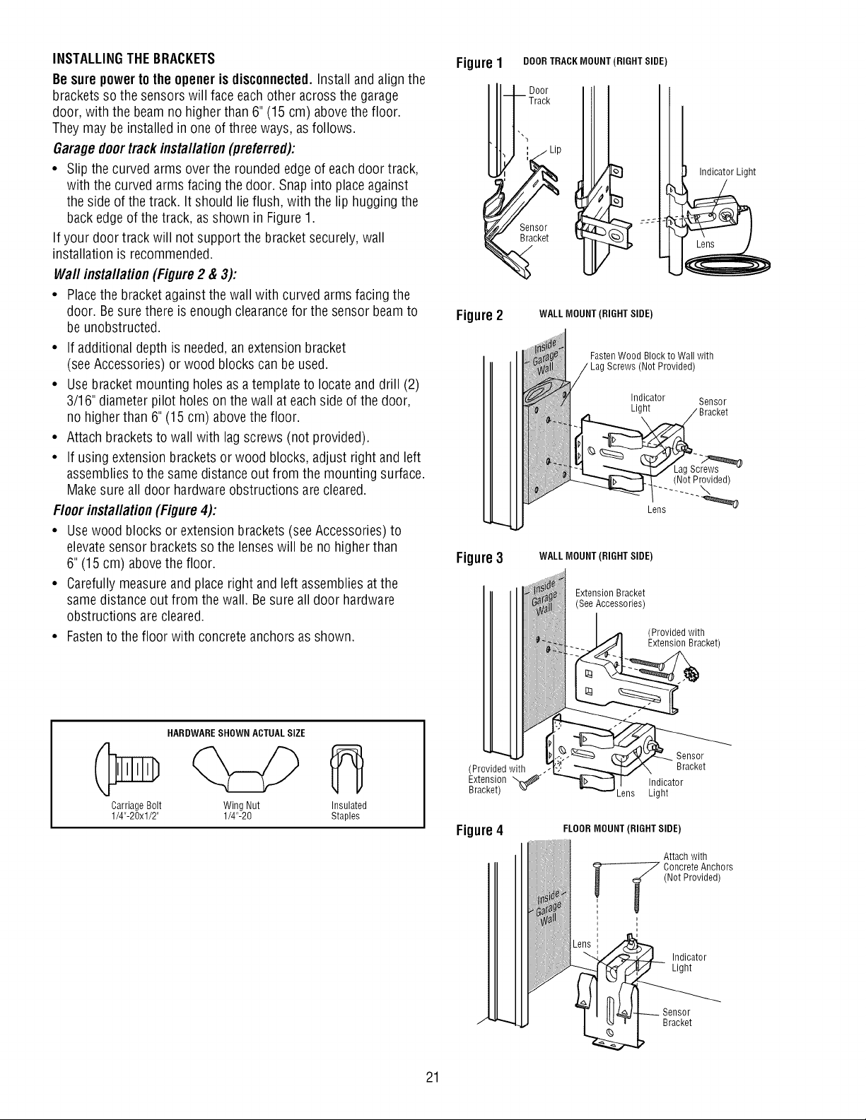
INSTALLINGTHEBRACKETS
Besurepower tothe opener is disconnected.Installand align the
brackets sothe sensors will faceeachother across the garage
door, with the beam no higher than 6"(15 cm) abovethe floor.
They may be installed in one of threeways, as follows.
Garagedoortrackinstallation(preferred):
• Slip the curvedarms overthe rounded edgeof eachdoor track,
with the curved arms facing the door. Snap into placeagainst
the side of the track. It should lie flush, with the lip huggingthe
back edgeof the track, asshown in Figure1.
If your door track will not support the bracket securely, wall
installation is recommended.
Waftinstallation (Figure2 & 3):
• Placethe bracketagainstthe wall with curved arms facing the
door. Besurethere is enoughclearancefor the sensor beamto
be unobstructed.
• If additional depth is needed,anextension bracket
(seeAccessories) or wood blocks can be used.
• Usebracketmounting holes asatemplateto locateanddrill (2)
3/16" diameter pilot holeson the wall at eachside ofthe door,
no higherthan 6" (15 cm) abovethe floor.
• Attach bracketsto wall with lag screws (not provided).
• If using extension bracketsor wood blocks, adjust right andleft
assembliesto thesame distanceout from the mounting surface.
Make sureall door hardware obstructions arecleared.
Floorinstallation (Figure4):
• Usewood blocks orextension brackets (seeAccessories) to
elevatesensor brackets sothe lenses will beno higher than
6"(15 cm) abovethe floor.
• Carefullymeasureand placeright andleft assembliesat the
same distanceout from the wall. Besure alldoor hardware
obstructions are cleared.
• Fastento the floor with concreteanchors as shown.
FigureI DOORTRACKMOUNT(RIGHT SIDE)
t Door
, Track
;zz -
Figure2 WALLMOUNT (RIGHT SIDE)
Figure3
FastenWood Blockto Wall with
WALLMOUNT (RIGHT SIDE)
(Not Provided)
Indicator Sensor
Light
_k Bracket
Y L2g._
Lens
Exteos,ooorac et
(SeeAccessories)
(Provided with
a
(Not Provided)
HARDWARESHOWN ACTUALSIZE
Carriage Bolt Wing Nut Insulated
1/4"-20xl/2" 1/4"-20 Staples
21
!I___:'- _acket)
"" _ Sensor
(Provided with .-__ Bracket
Extension _ b_.. -- I! Indicator
Bracket) ,.v _Lens Light
Figure4
J
FLOORMOUNT (RIGHT SIDE)
Attach with
Concrete Anchors
(Not Provided)
Sensor
Bracket
Indicator
Light
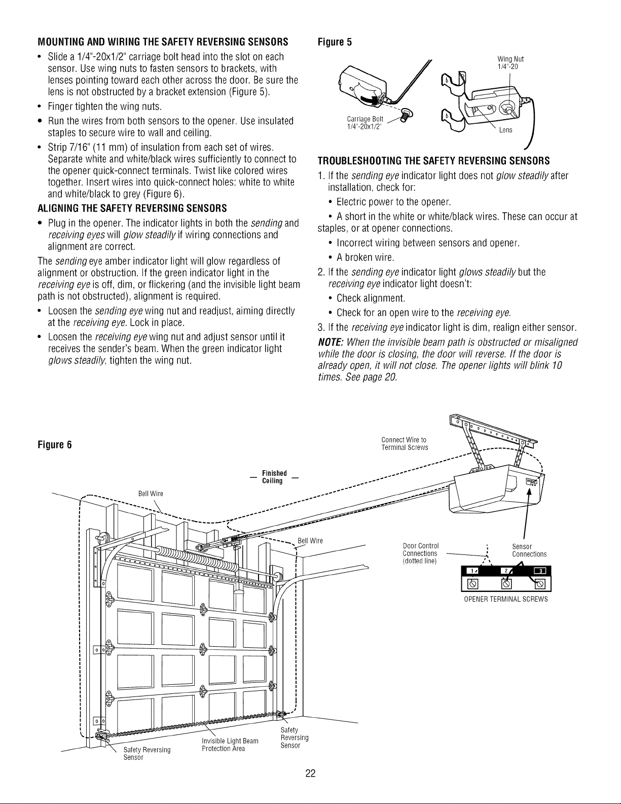
MOUNTINGAND WIRINGTHESAFETYREVERSINGSENSORS
• Slide a 1/4"-20xl/2" carriagebolt headinto the slot on each
sensor. Usewing nuts to fasten sensorsto brackets,with
lenses pointing toward each other across the door. Besure the
lens is not obstructed by abracket extension (Figure5).
• Fingertighten thewing nuts.
• Runthe wires from both sensorsto the opener. Useinsulated
staplesto securewire to wall andceiling.
• Strip 7/16" (11 mm) of insulationfrom eachset of wires.
Separatewhite andwhite/black wires sufficiently to connectto
the opener quick-connectterminals. Twist like coloredwires
together. Insert wires into quick-connect holes:white to white
and white/black togrey (Figure 6).
ALIGNINGTHESAFETYREVERSINGSENSORS
• Plugin the opener. Theindicator lights in both the sendingand
receivingeyeswill glow steadilyif wiring connections and
alignment are correct.
Thesending eyeamber indicator light will glow regardlessof
alignment or obstruction. If the greenindicator light inthe
receiving eyeis off, dim, orflickering (and the invisible light beam
path is not obstructed), alignmentis required.
• Loosenthe sending eyewing nut and readjust, aiming directly
atthe receiving eye.Lock inplace.
• Loosenthe receivingeyewing nut and adjust sensor until it
receivesthe sender's beam. When the greenindicator light
glows steadily,tightenthe wing nut.
Figure5
Wing Nut
1/4"-20
1/4"-20xl/2"
Carriage Bolt _
TROUBLESHOOTINGTHESAFETYREVERSINGSENSORS
1. If the sending eyeindicatorlight does not glow steadily after
installation, checkfor:
• Electricpower to the opener.
• A short in the white orwhite/black wires. These can occur at
staples, or atopener connections.
• Incorrect wiring betweensensors andopener.
• A broken wire.
2. If the sending eyeindicatorlight glows steadilybut the
receivingeyeindicator light doesn't:
• Checkalignment.
• Checkfor anopenwire to the receiving eye.
3. If the receivingeyeindicator light isdim, realigneithersensor.
NOTE:When the invisiblebeam path is obstructed or misaligned
while the door is closing, the door will reverse.If the door is
already open, it will not close. The openerlights will blink 10
times. Seepage20.
Figure6
Finished
Ceiling
Connect Wire to
Terminal Screws
DoorControl ; Sensor
Connections Connections
(dotted line)
OPENERTERMINAL SCREWS
22

INSTALLATION STEP 1 1
FastentheDoorBracket
Follow instructions which applyto your door typeas illustrated
below or on the following page.
A horizontalreinforcementbraceshouldbe longenoughto be
securedto two orthree vertical supports.Avertical
reinforcementbraceshouldcoverthe heightof thetop panel.
Figure1 shows one pieceof angle iron as the horizontal brace.
Forthe vertical brace, 2 pieces of angle iron are usedto createa
U-shaped support. Thebest solution isto checkwith your garage
door manufacturerfor an openerinstallation door reinforcement
kit.
NOTE:Many door reinforcementkits provide for direct
attachment of the clevis pin and doorarm. In this caseyou will
not need the doorbracket,proceed to Step 12.
SECTIONALDOORS
1. Centerthe door bracketon the previously marked vertical
centerline usedfor the headerbracket installation. Notecorrect
UPplacement,as stamped insidethe bracket.
2. Position the top edgeof the bracket2"-4"(5-10 cm) below the
top edge ofthe door, ORdirectly below any structural support
across the top of the door.
3. Mark, drill holes and install as follows, depending on your
door's construction:
Metal orlight weightdoorsusinga verticalangleiron brace
betweenthe doorpanel supportand the doorbracket:
• Drill 3/16" fastening holes. Securethe door bracket using the
two 1/4"-14x5/8"self-threading screws. (Figure2A)
• Alternately, usetwo 5/16" bolts, lock washers andnuts
(not provided). (Figure2B)
Metal, insulatedor light weightfactoryreinforceddoors:
• Drill 3/16" fastening holes. Securethe door bracket using the
self-threading screws (Figure3).
WoodDoors:
• Usetop and bottom or sideto side door bracket holes. Drill
5/16" holes through the door and secure bracket with 5/16"x2"
carriage bolts, lock washersand nuts (not provided). (Figure4)
NOTE:The1/4"-14x5/8"self-threading screws are not intended for
use on wood doors.
HARDWARE SHOWN
ACTUAL SIZE
Self-Threading
Screw
1/4"-14x5/8"
Fiberglass,aluminum or lightweight steel garagedoors WILL
REQUIREreinforcement BEFOREinstallation of door bracket.
Contactyour door manufacturer for reinforcement kit.
Door
Bracket
Location
HORIZONTALANDVERTICAL
REINFORCEMENTIS NEEDEDFOR
Vertical
Centerline
of Garage
Door
LIGHTWEIGHTGARAGEDOORS
(FIBERGLASS,ALUMINUM, STEEL,
DOORSWITH GLASS PANEL, ETC.).
(NOT PROVIDED)
III IIII I
Figure 1
Vertical
_fl_,,_olOlVerti:_iC_ri:trline
arage Door
Door gracket_" _-UP
Self-Threading---"_
Screw 1/4"-14x5/8"
Figure 2A
ertical
Centerline
of GarageDoor
Self-Threading
Screw
1/4"-14x5/8"
Figure 3
(Not Provided 11_
_'C_% [Io101 VerticalCenterline
"%." [Io101 of Garage Door
- iloH ==
Door Bracket
Lock Washer 5/16'_.
Nut 5/16"- 18
J
5/16"x2" -.
(Not Provided)
Bolt
Vertical
Centerline
of Garage
Door
Figure 2B
Inside Edge
of Door or
Reinforcement Board
Figure 4
23
 Loading...