

Craftsman 13953915DM Owner’s Manual
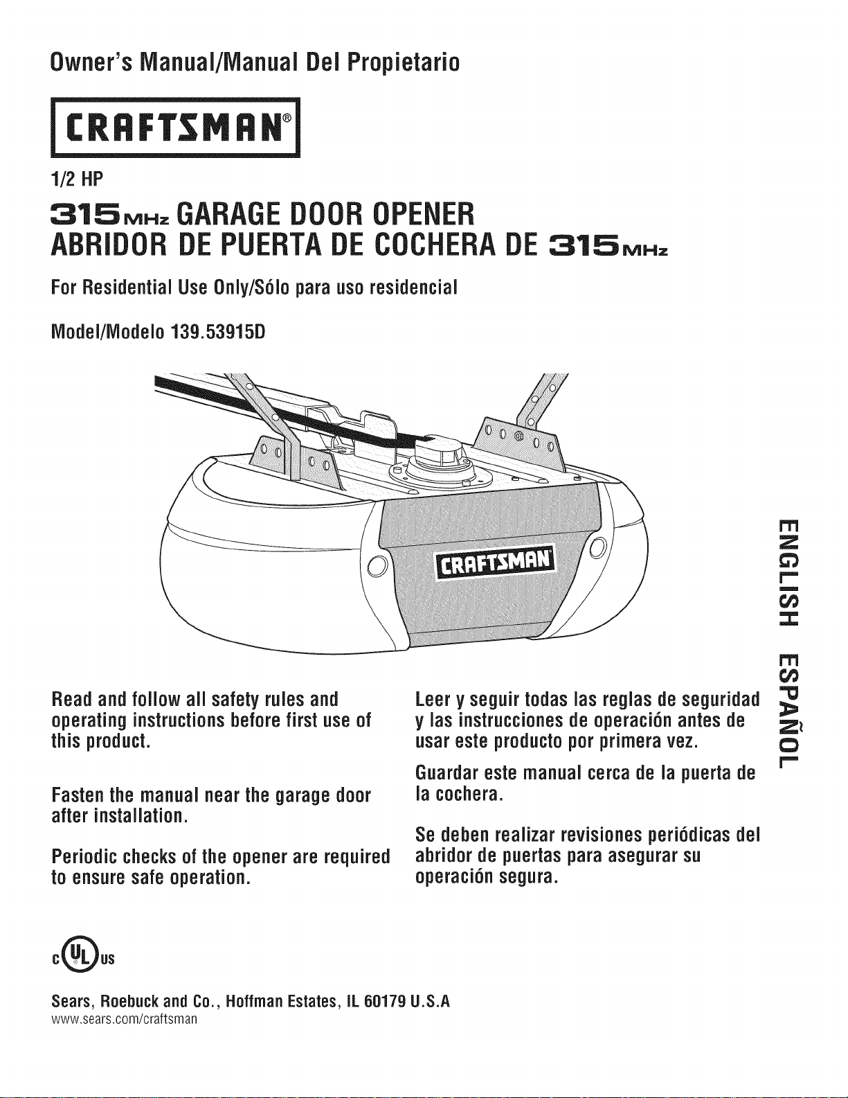
Owner'sIVianuai/iVianualDel Propietario
1/2HP
315_.=, GARAGE DOOR OPENER
ABBIDOB DE PUEBTA DE COCHEBA DE
For Residential UseOnly/S6Jopara usoresidencial
iVlodei/iVlodelo13g.53915D
31.SMNz
r'T'l
z
1,,,,,,
m
f,i}
:3:
Bead andfoiJowaiJsafety ruJesand
operating instructionsbeforefirst use of
thisproduct.
Fastenthe manualnearthegaragedoor
Leery seguirtodaslas reglasde seguridad
y las instruccionesde operaci6n antes de
usareste productoporprimeravez.
Guardareste manualcercade la puertade
la cochera.
after installation.
Sedeben realizar revisionesperi6dicasdel
Periodic checksof the opener are required
to ensure safe operation.
abridor de puertaspara asegurar su
operaci6n segura.
oQos
Sears, Roebuck and Co., HoffrnanEstates,IL 60179U.S.A
www.sears.com/craftsman
Z_
C}
I""
TABLE OF CONTENTS
Introduction 2-7
Safetysymbol and signal word review ..................... 2
Preparing your garagedoor ............................. 3
Tools needed ........................................ 3
Planning ........................................... 4-5
Carton inventory ...................................... 6
Hardware inventory.................................... 7
Assembly 8-11
Assemblethe rail and install the trolley .................... 8
Fastenthe rail to the motor unit and Install the idler pulley ..... 9
Install the belt ....................................... 10
Tighten the belt...................................... 10
Install the sprocket cover ............................. 11
Installation 11-26
Installation safety instructions .......................... 11
Determinethe headerbracket location.................... 12
Install the headerbracket .............................. 13
Attach the rail to the headerbracket...................... 14
Position the opener................................... 14
Hangthe opener ..................................... 15
Install the door control ................................ 16
Install the lights ..................................... 17
Attach the emergencyreleaserope and handle ............. 17
Electrical requirements ................................ 18
Install The Protector System®......................... 19-22
Fastenthe door bracket ............................. 23-24
Connectthe door arm to thetrolley .................... 25-26
Adjustment 27-29
Adjust thetravel limits ................................ 27
Adjust theforce ..................................... 28
Testthe safety reversalsystem.......................... 29
TestThe Protector System®............................ 29
Operation 30-34
Operationsafety instructions ........................... 30
Using your garagedoor opener ......................... 30
Using the wall-mounted door control ..................... 31
To open the door manually............................. 31
Careofyour garagedoor opener ........................ 32
Having a problem? ................................... 33
Diagnostic chart ..................................... 34
Programming 35-36
To add or reprograma hand-held remote control ........... 35
To erase all codes.................................... 35
3-Function Remotes .................................. 35
To add, reprogram or change a KeylessEntry PIN........... 36
Repair Parts 37-38
Rail assembly parts .................................. 37
Installation parts ..................................... 37
Motor unit assembly parts ............................. 38
Accessories 39
Warranty
RepairParts& Service
Back Cover
39
INTRODUCTION
SafetySymbolandSignal WordReview
This garagedoor opener hasbeen designedandtested to offer safe serviceprovided it is installed,operated, maintainedand tested in
strict accordancewith the instructions and warnings contained in this manual.
Whenyou seethese Safety Symbols andSignalWords on the
following pages,they will alertyou to the possibility of serious
Mechanical
Electrical
injury or deathif you do not comply with the warnings that
accompanythem. The hazardmaycome from something
mechanicalor from electric shock. Readthe warnings carefully.
Whenyou seethis Signal Word on the following pages,itwill
alertyou to the possibility of damageto your garagedoorand/or
the garagedoor openerifyou do not comply with the cautionary
statements that accompany it. Readthem carefully.
Preparingyourgaragedoor
Beforeyou begin:
• Disablelocks.
• Removeany ropesconnectedto garagedoor.
• Completethefollowingtestto makesure your garagedoor is
balancedand is not sticking or binding:
1. Lift the door about halfwayasshown. Releasethe door. If
balanced,it should stay in place, supported entirely by its
springs.
2. Raiseand lower the door to see if there is any binding or
sticking.
If your door binds, sticks, or is out of balance,call a trained door
systems technician.
To prevent possibleSERIOUSINJURYor DEATH:
• ALWAYScall a trained door systems technician if garage
door binds, sticks or is out of balance.An unbalanced
garagedoor may NOTreversewhen required.
• NEVERtry to loosen, move or adjust garagedoor, door
springs, cables, pulleys,brackets or their hardware,ALL of
which are under EXTREMEtension.
• DisableALL locks and removeALL ropesconnected to
garagedoor BEFOREinstalling and operatinggarage door
opener to avoid entanglement.
To preventdamage to garage door and opener:
• ALWAYSdisable locks BEFOREinstalling and operating the
opener.
• ONLYoperate garagedoor opener at 120V,60 Hzto avoid
malfunction and damage.
SectionalDoor
One-Piece Door
(Optional)
Tools needed
During assembly, installation and adjustment of the opener,
instructions will call for handtools as illustrated below.
Pencil
Hack Saw
Claw Hammer
Screwdriver
Stepladder
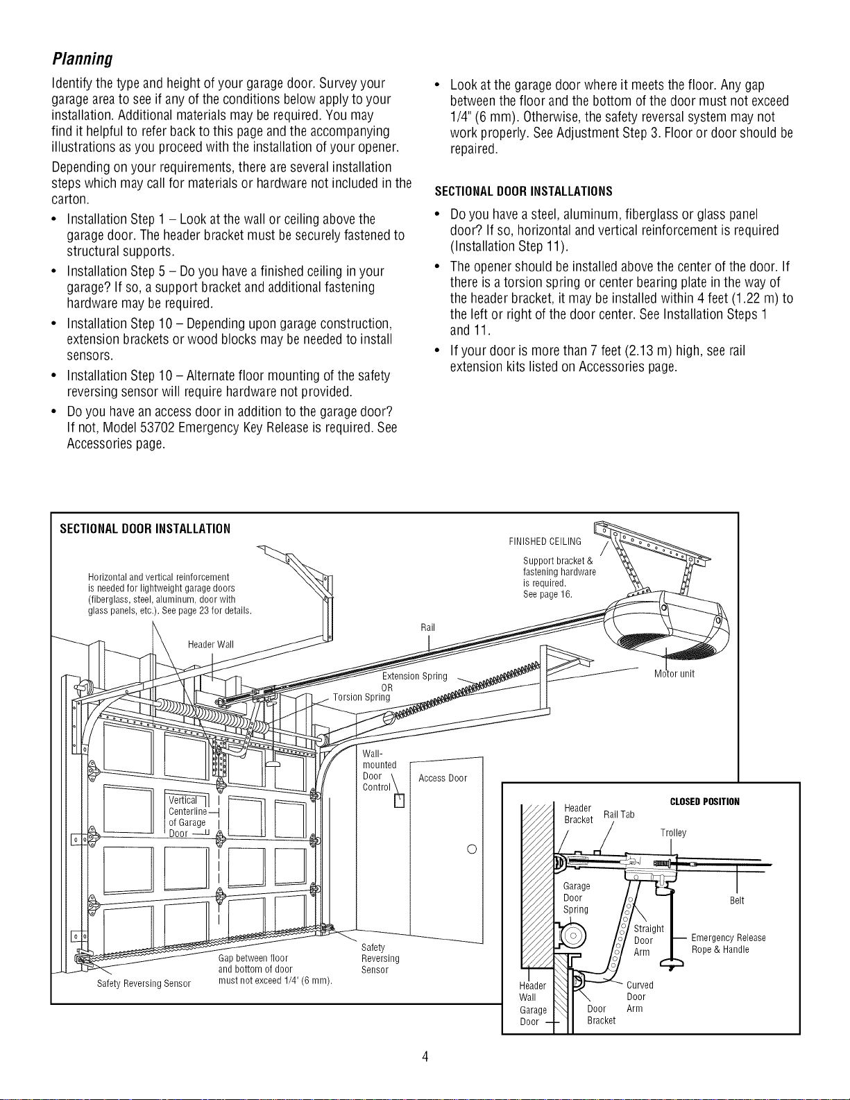
Planning
Identify the type and height ofyour garagedoor. Surveyyour
garageareato see if anyof the conditions below applyto your
installation. Additional materials may be required.You may
find it helpful to referback to this pageandthe accompanying
illustrations asyou proceed with the installation of your opener.
Dependingon your requirements,there are severalinstallation
stepswhich maycall for materials or hardwarenot included in the
carton.
• Installation Step1 - Lookat the wall or ceiling abovethe
garagedoor. The headerbracketmust besecurelyfastened to
structural supports.
• Installation Step5 - Doyou havea finished ceiling in your
garage? If so, a support bracketand additional fastening
hardwaremay be required.
• Installation Step10 - Dependingupon garageconstruction,
extension bracketsor wood blocks may be neededto install
sensors.
• Installation Step10 -Alternate floor mounting of the safety
reversing sensor will require hardwarenot provided.
• Doyou havean accessdoor in addition to the garagedoor?
If not, Model 53702 EmergencyKeyReleaseis required.See
Accessoriespage.
Look at the garage door where it meetsthe floor. Any gap
betweenthe floor and the bottom of the door must not exceed
1/4" (6 mm). Otherwise,the safety reversalsystem may not
work properly. SeeAdjustment Step3. Flooror door should be
repaired.
SECTIONALDOORINSTALLATIONS
• Doyou havea steel, aluminum, fiberglass or glass panel
door? If so, horizontal andvertical reinforcement is required
(Installation Step 11).
• Theopener should be installed abovethe center of the door. If
there is atorsion spring or center bearing plate in the way of
the headerbracket, it may be installedwithin 4 feet (1.22 m) to
the left or right of the door center.See Installation Steps 1
and 11.
• If your door is morethan 7 feet (2.13 m) high, seerail
extension kits listed on Accessories page.
SECTIONALDOORINSTALLATION
Horizontal and vertical reinforcement
is neededfor lightweight garage doors
(fiberglass, steel, aluminum, door with
glass panels, etc.). See page 23 for details.
Header Wall
Centerline--I
of Garage
Door
Gap between floor
and bottom of door
Safety Reversing Sensor
must not exceed 1/4" (6 mm).
Rail
Extension Spring
OR
Spring
Wall-
mounted
Door \ AccessDoor
Control _[]
Safety
Reversing
Sensor
FINISHEDCEILING
Support bracket &
fastening hardware
is required.
See page16.
tor unit
-- Header CLOSEDPOSITION
Bracket
RailTab
0
_ __..._._ / L Trilley
_/_ Garage _ I
V///A Door 'ol "1 Belt
Fi/A Spring /J', I
_'_ /i / :t!_ht _ EmergencyRe,ease
Aim
Header _ _ _ Curved
Wall _J \ Door
Garage _ J Door Arm
Door--I-11 Bracket
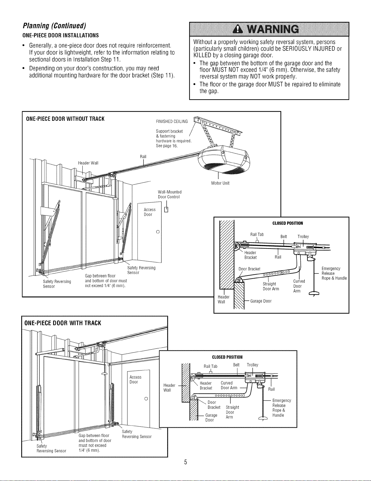
Planning(Continued)
ONE-PIECEDOORINSTALLATIONS
• Generally,aone-piecedoor does not require reinforcement.
If your door is lightweight, refer to the information relatingto
sectionaldoors in Installation Step 11.
• Dependingon your door's construction, you may need
additional mounting hardwarefor the door bracket(Step 11).
Without a properly working safety reversalsystem, persons
(particularly small children) could be SERIOUSLYINJUREDor
KILLEDby a closing garagedoor.
• Thegap betweenthe bottom of the garagedoor andthe
floor MUSTNOTexceed1/4" (6 mm). Otherwise,the safety
reversalsystem may NOTwork properly.
• Thefloor or the garagedoor MUSTbe repairedto eliminate
the gap.
ONE-PIECEDOORWITHOUTTRACK
Header Wall
Gap between floor
SafetyReversing
Sensor
andbottomofdoormust
notexceed1/4"(6 mm).
Rail
Access
Door
Safety Reversing
Sensor
FINISHEDCEILING
Support bracket
& fastening
hardware is required.
See page 16.
Wall-Mounted
Door Control
0
Motor Unit
CLOSEDPOSITION
Rail Tab Belt Trolley
.__ _ _ I
Header I
Door Bracket _ J,/ I Emergency
__ I-- pReo_eaS_Handle
_irgAhlnl iii_ed 1_
Header
flail "safety
H__oor Reversing Sensor J
Safety must not exceed |
Reversing Sensor 1/4" (6 mm). |
and bottom of door J
/
,_}-- GarageDoor °
CLOSEDPOSITION
Rail Tab Belt Trolley
II
Straight
Door
Door
Arm
Rail
Emergency
Release
Rope &
Handle

CartonInventory
Your garage door opener is packagedin one carton which contains
the motor unit and all parts illustrated below. Accessorieswill
dependon the model purchased. If anything is missing, carefully
SECURITY÷'-_
3-Function Remote Control (2)
Motion Detecting Control Console
Sprocket Cover
checkthe packing material. Hardwarefor assemblyand installation
is shown on the next page.Savethe carton and packingmaterial
until installation and adjustment iscomplete.
Trolley
SECURITY÷_
Keyless Entry
Rail
Center/Back
Sections
Rail
Front (header)
Section
Safety Reversing
Sensor Bracket (2)
Motor Unit with 2 Light Lenses
Idler Pulley
@
Header Bracket
The Protector System®
(2) Safety Reversing Sensors
(1 Sending Eye and 1 Receiving Eye)
with 2-Conductor White & White/Black
BellWire attached
Belt
Door Bracket
Curved Door
Arm Section
2-Conductor Bell Wire
White & White/Red
Safety Labels
and
Literature
Hanging Brackets
Straight Door
Arm Section
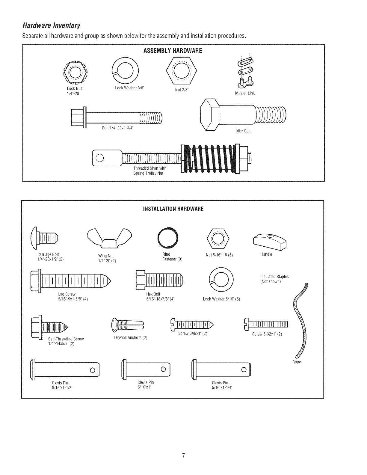
HardwareInventory
Separateall hardware andgroup as shown below for the assembly andinstallation procedures.
ASSEMBLYHARDWARE
Lock Nut Lock Washer 3/8" Nut 3/8"
1/4"-20 Master Link
Bolt 1/4"-20xl-3/4" _ [_
J
Idler Bolt
I
©
Threaded Shaft with
Spring Trolley Nut
iNSTALLATiONHARDWARE
Carriage Bolt
1/4"-20xl/2" (2)
Lag Screw Hex Bolt
5/16"-9xl-5/8" (4) 5/16"-18x7/8" (4) Lock Washer 5/16" (5)
_ng Screw
1/4"-14x5/8"(2)
{!
Clevis Pin Clevis Pin
5/16"xl -1/2" 5/16"xl"
Wing Nut Ring Nut 5/16"-18 (6)
1/4"-20 (2) Fastener (3)
Drywall Anchors (2)
Screw 6ABxl" (2)
Clevis Pin
5/16"x1-1/4"
Insulated Staples
(Not shown)
Screw 6-32x1" (2)
Rope
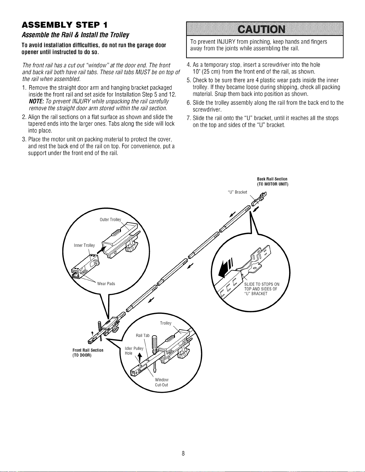
ASSEMBLY STEP 1
Assemblethe Rail & Install the Trolley
Toavoidinstallationdifficulties,do notrunthegarage door
openeruntil instructedtodoso.
To prevent INJURYfrom pinching, keephands and fingers
awayfrom thejoints while assembling the rail.
Thefront railhasa cut out "window" at the door end. Thefront
and back rail both haverail tabs. Theserail tabs MUSTbe ontop of
the rail whenassembled.
1. Removethestraight door arm and hangingbracket packaged
inside the front rail and set asidefor Installation Step5 and 12.
NOTE:Toprevent INJURY whileunpacking the rail carefully
remove the straight doorarm stored within the rail section.
2. Align the railsections on aflat surface asshown and slidethe
taperedends into the larger ones.Tabs along the side will lock
into place.
3. Placethe motor unit on packing materialto protect the cover,
and rest the back end of the rail on top. For convenience,put a
support under the front end of the rail.
Outer Trolley
4. As atemporary stop, insert a screwdriver into the hole
10"(25 cm) from the front endof the rail, asshown.
5. Checkto besurethere are4 plastic wear padsinsidethe inner
trolley. If they becamelooseduring shipping, checkall packing
material. Snapthem backinto position as shown.
6. Slide the trolley assemblyalongthe rail from the back endto the
screwdriver.
7. Slide the rail onto the "U" bracket,until it reachesall the stops
on the top andsides ofthe "U" bracket.
Back Rail Section
(TO MOTOR UNIT)
"U" Bracket
Inner Trolley
Wear Pads
FrontRail Section
(TO DOOR)
Rail Tab
Idler Pulley
Trolley
Window
Cut-Out
SLIDETO STOPS ON
TOP AND SIDESOF
"U" BRACKET
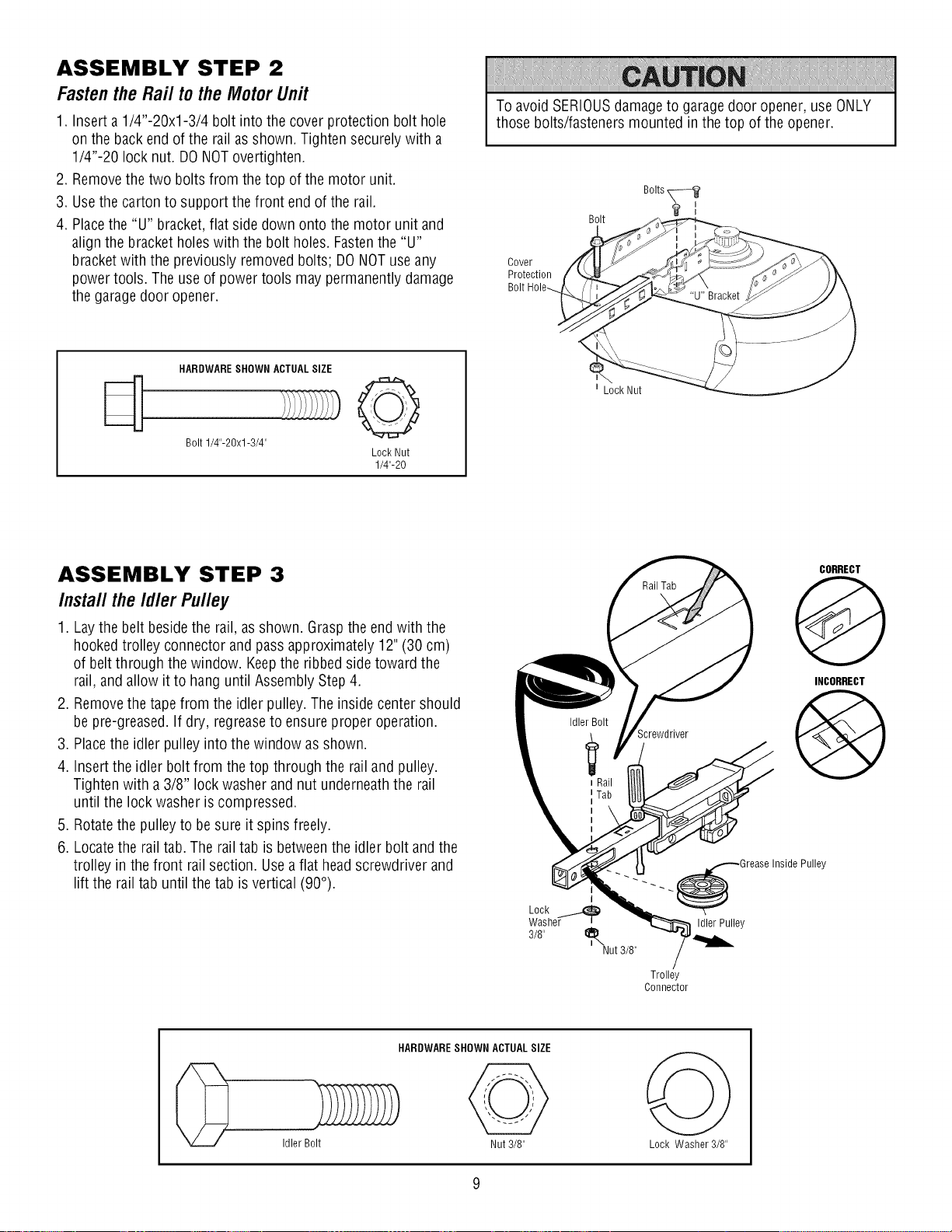
ASSEMBLY STEP 2
Fastenthe Rail to the MotorUnit
1. Inserta 1/4"-20xl-3/4 bolt into the coverprotection bolt hole
on the backend of the railasshown. Tighten securelywith a
1/4"-20 locknut. DONOTovertighten.
2. Removethe two bolts from thetop of the motor unit.
3. Usethe carton to support thefront endof the rail.
4. Placethe "U" bracket,flat side down onto the motor unit and
align the bracket holes with the bolt holes. Fastenthe "U"
bracketwith the previously removed bolts; DONOTuse any
power tools. Theuse of power tools may permanently damage
the garagedoor opener.
Toavoid SERIOUSdamageto garagedoor opener,use ONLY
those bolts/fasteners mounted in the top of the opener.
Bolts
Bolt
Cover
Protection
HARDWARESHOWN ACTUALSIZE
Bolt 1/4"-BOx1-3/4"
Lock Nut
1/4"-20
ASSEMBLY STEP 3
Install the Idler Pulley
1. Laythe belt besidethe rail, asshown. Graspthe end with the
hookedtrolley connector and pass approximately 12"(30 cm)
of beltthrough thewindow. Keepthe ribbed side toward the
rail,and allow it to hang until AssemblyStep4.
2. Removethe tapefrom the idler pulley.The insidecenter should
be pre-greased. If dry, regreaseto ensure proper operation.
3. Placethe idler pulley into the window as shown.
4. Insertthe idler bolt from the top through the rail and pulley.
Tighten with a 3/8" lock washer and nut underneaththe rail
until the lock washer is compressed.
5. Rotatethe pulleyto be sure it spins freely.
6. Locatethe railtab. The railtab is betweenthe idler bolt and the
trolley in the front rail section. Usea flat headscrewdriver and
lift the rail tab until the tab is vertical (90°).
I
t Lock Nut
CORRECT
@
INCORRECT
Screwdriver
@
Pulley
._._.. _Grease InsideI
Lock
Washer t Idler Pulley
3/8" t_Nut 3/8"
Trolley
Connector
HARDWARESHOWN ACTUALSIZE
Idler Bolt Nut 3/8" Lock Washer 3/8"
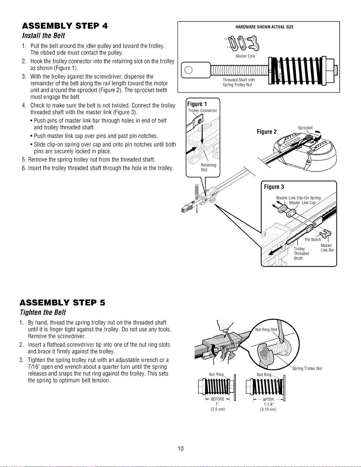
ASSEMBLY STEP 4
Install theBelt
1. Pull the belt around the idler pulley and toward the trolley.
The ribbed sidemust contact the pulley.
2. Hookthe trolley connector into the retainingslot on the trolley
as shown (Figure 1).
3. With the trolley againstthe screwdriver, dispense the
remainderof the belt along the rail lengthtoward the motor
unit and aroundthe sprocket (Figure2). The sprocket teeth
must engagethe belt.
4. Checkto makesure the belt is not twisted. Connectthe trolley
threaded shaft with the master link (Figure3).
• Pushpins of master link bar through holes in end of belt
and trolley threaded shaft.
• Pushmaster link capover pins and past pin notches.
• Slide clip-on spring over cap and onto pin notches until both
pins are securelylocked in place.
5. Removethe spring trolley nut from the threadedshaft.
6. Insertthe trolley threaded shaft through the hole inthe trolley.
HARDWARESHOWN ACTUALSIZE
Master Link
[©
Threaded Shaft with
Spring Trolley Nut
ure I
Sprocket
Figure2 -,,,
Figure3
ASSEMBLY STEP 5
Tighten the Belt
1. By hand,thread the spring trolley nut on the threaded shaft
until it is finger tight againstthe trolley. Do not use anytools.
Removethe screwdriver.
2. Insert a flathead screwdriver tip into one of the nut ring slots
and brace it firmly against the trolley.
3. Tightenthe spring trolley nut with an adjustablewrench or a
7/16" open end wrench about a quarterturn until the spring
releasesand snaps the nut ring against the trolley. This sets
the spring to optimum belt tension.
Nut Ring
I- BEFORE-I
1"
(2.5cm)
Master Link Clip-On Spring
Nut Ring _ rl
F liiiii l
1-1/4"
(3.18 cm)
Master Link Ca
"Spring Trolley Nut
10
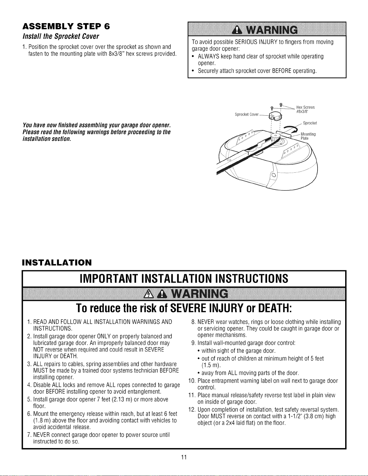
ASSEMBLY STEP 6
Install the Sprocket Cover
1. Position the sprocket cover over the sprocket as shown and
fastento the mounting plate with 8x3/8" hexscrews provided.
Youhavenowfinishedassemb/ingyourgarage dooropener.
P/easeread the fo//owingwarnings beforeproceedingtothe
insta//ationsection.
Toavoid possible SERIOUSINJURYto fingers from moving
garagedoor opener:
• ALWAYSkeep hand clearof sprocket while operating
opener.
• Securelyattach sprocket cover BEFOREoperating.
_Hex Screws
Sprocket Cover_ #8x3/8"
, / Sprocket
Plate
INSTALLATION
IMPORTANTINSTALLATIONINSTRUCTIONS
ToreducetheriskofSEVEREINJURYorDEATH:
1. READAND FOLLOWALL INSTALLATIONWARNINGSAND
INSTRUCTIONS.
2. Installgarage door openerONLYon properly balancedand
lubricated garage door. An improperly balanceddoor may
NOTreversewhen required and could result in SEVERE
INJURYor DEATH.
3. ALL repairsto cables,spring assembliesand other hardware
MUSTbe made by atrained door systemstechnician BEFORE
installing opener.
4. DisableALL locks and removeALL ropesconnected to garage
door BEFOREinstalling openerto avoid entanglement.
5. Installgarage door opener7feet (2.13 m) or moreabove
floor.
6. Mount the emergency releasewithin reach,but at least 6 feet
(1.8 m) above thefloor and avoiding contact with vehiclesto
avoid accidental release.
7. NEVERconnect garagedoor openerto power sourceuntil
instructed to do so.
8. NEVERwearwatches, rings or loose clothing while installing
or servicing opener.They could be caught in garagedoor or
opener mechanisms.
9. Installwall-mounted garagedoor control:
• within sight of the garage door.
• out of reachof children at minimum height of 5 feet
(1.5 m).
• awayfrom ALL moving parts of thedoor.
10. Placeentrapment warning labelon wall nextto garage door
control.
11. Placemanual release/safetyreversetest label in plain view
on inside of garagedoor.
12. Uponcompletion of installation, test safety reversalsystem.
Door MUST reverseon contact with a1-1/2" (3.8 cm) high
object (or a 2x4 laid flat) on the floor.
11
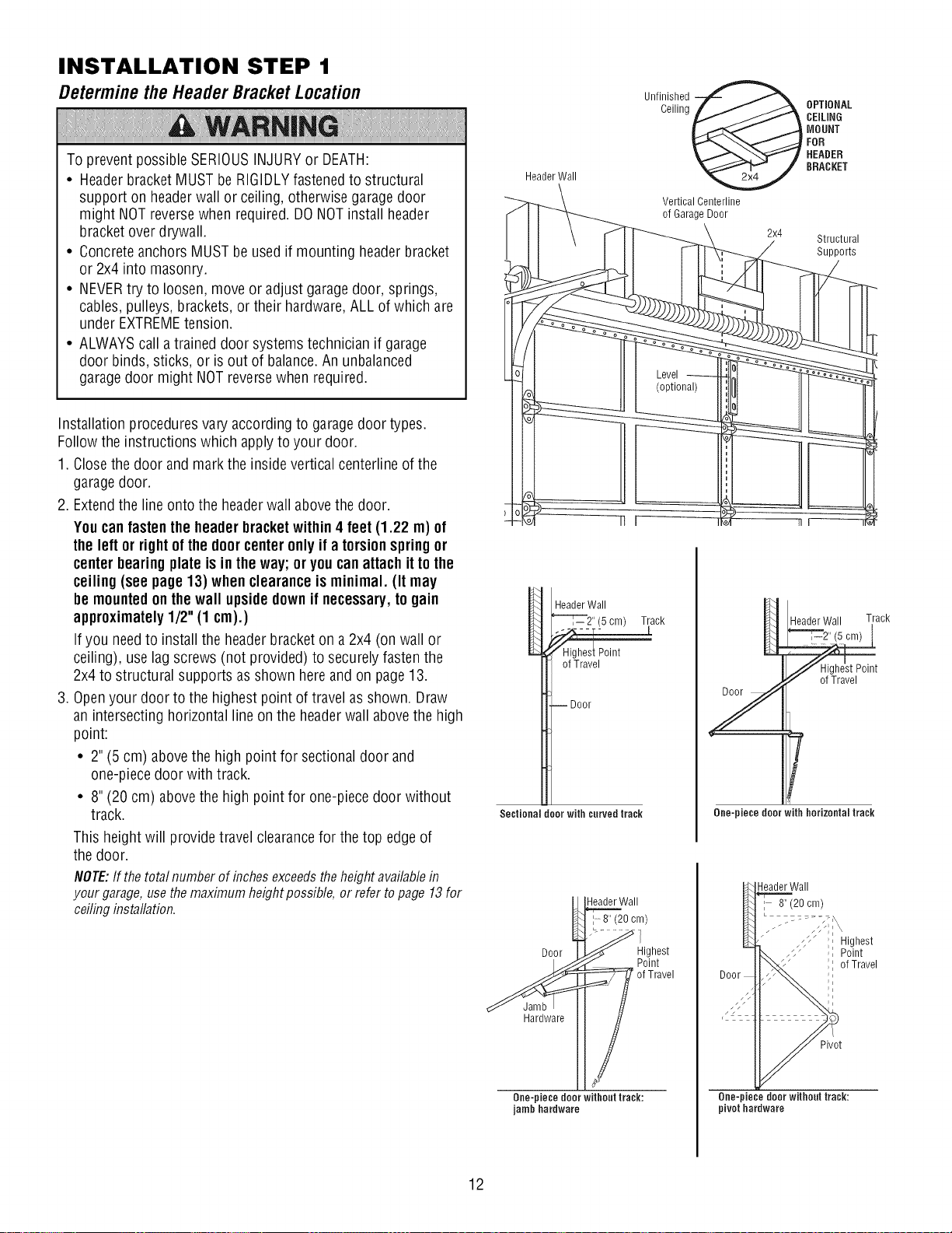
INSTALLATION STEP 1
Determinethe HeaderBracketLocation
To prevent possibleSERIOUSINJURYor DEATH:
• Headerbracket MUSTbe RIGIDLYfastenedto structural
support on headerwall or ceiling, otherwise garagedoor
might NOTreversewhen required. DONOTinstall header
bracketover drywall.
• Concreteanchors MUSTbe usedif mounting headerbracket
or 2x4 into masonry.
• NEVERtry to loosen, move or adjustgaragedoor, springs,
cables,pulleys, brackets,or their hardware, ALL of which are
under EXTREMEtension.
• ALWAYScall a trained door systems technician if garage
door binds, sticks, or is out of balance.An unbalanced
garagedoor might NOTreversewhen required.
Installation procedures vary according to garagedoor types.
Follow the instructions which applyto your door.
1. Closethe door and mark the inside vertical centerline of the
garagedoor.
2. Extendthe line onto the headerwall above the door.
Youcanfastenthe headerbracketwithin4 feet (1.22 m) of
the left or rightofthe doorcenteronlyif a torsionspringor
centerbearingplate is inthe way;or youcan attachit to the
ceiling(see page 13) whenclearanceisminimal. (It may
be mountedonthewall upsidedownif necessary,to gain
approximately1/2"(1 cm).)
Ifyou needto install the header bracketon a 2x4 (on wall or
ceiling), uselag screws (not provided)to securely fastenthe
2x4 to structural supports as shown here and onpage 13.
3. Openyour door to the highest point of travel as shown. Draw
an intersecting horizontal line on the headerwall abovethe high
point:
• 2" (5 cm) abovethe high point for sectionaldoor and
one-piecedoor with track.
• 8" (20 cm) abovethe high point for one-piecedoor without
track.
This height will provide travel clearancefor the top edge of
the door.
NOTE:If thetotalnumberofinchesexceedstheheightavailablein
yourgarage,usethemaximumheightpossible,or refertopage13for
ceilinginstallation.
HeaderWall
HeaderWall
(5cm) Track
of Travel
--Door
Sectional door with curved track
_\\Wall
U8/2°0 /
Door__J _ig_st
Ceiling OPTIONAL
Unfinished @
Vertical Centerline
of GarageDoor
CEiLiNG
MOUNT
FOR
HEADER
BRACKET
2x4 Structural
Header Wall Track
Y
T
One-piece door with horizontal track
HeaderWall
I 8" (20cm)
_;, Highest
Door
Supports
Point
of Travel
_Hardware [[ of Travel
One-piece door without track:
jamb hardware
12
Pivot
One-piece door without track:
pivothardware
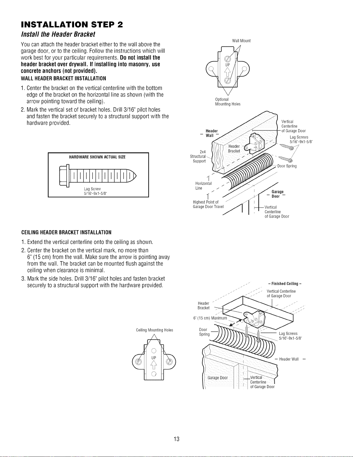
INSTALLATION STEP 2
Install theHeaderBracket
You can attachthe headerbracketeither to the wall abovethe
garagedoor, or to the ceiling. Follow the instructions which will
work best for your particular requirements. Do not installthe
header bracket over drywall. If installingintomasonry,use
concreteanchors(notprovided).
WALLHEADERBRACKETINSTALLATION
1. Centerthe bracketon the vertical centerline with the bottom
edgeof the bracketon the horizontalline asshown (with the
arrow pointing toward the ceiling).
2. Mark the vertical set of bracketholes. Drill 3/16" pilot holes
and fastenthe bracketsecurely to a structural support with the
hardwareprovided.
HARDWARESHOWN ACTUALSIZE
LagScrew
5/16"-9xl-5/8"
2x4
Structural
Support
J
1
Horizontal
Line
"[ j
Highest Point of
Garage Door Travel
Wall Mount
_p
Optional
Mounting Holes
Vertical
Centerline
Centerline
of Garage Door
GarageDoor
LagScrews
5/16"-9xl -5/8"
CEILINGHEADERBRACKETINSTALLATION
1. Extendthe vertical centerlineonto the ceiling asshown.
2. Centerthe bracketon the vertical mark, no more than
6"(15 cm) from the wall. Makesure the arrow is pointing away
from the wall. The bracketcanbe mounted flush againstthe
ceiling when clearanceis minimal.
3. Mark the side holes. Drill 3/16" pilot holes andfasten bracket
securelyto astructural support with the hardwareprovided.
Ceiling Mounting Holes
Header /
Bracket
6" (15 cm) Maximum
Door
Spring
- Finished Ceiling -
Vertical Centerline
of Garage Door
-- Lag Screws
-_ 5/16"-9xl-5/8"
- HeaderWall -
Centeriine
of GarageDoor
13
Header Wall
Header Bracket
Idler Pulley
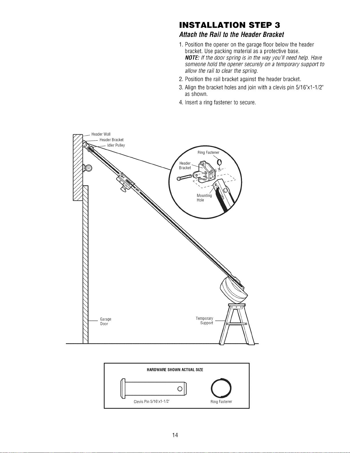
INSTALLATION STEP 3
AttachtheRail tothe HeaderBracket
1. Position the opener on the garagefloor below the header
bracket. Usepacking material as a protective base.
NOTE:If the door spring is in the wayyou'll needhelp. Have
someone hold the opener securely on a temporary support to
allow the rail to clear the spring.
2. Position the rail bracket againstthe headerbracket.
3. Align the bracket holes and join with aclevis pin 5/16"x1-1/2"
as shown.
4. Inserta ring fastenerto secure.
Rinc
\
\
__ Garage
Door
Mounting
Hole
Temporary
Support
HARDWARESHOWN ACTUALSIZE
Clevis Pin 5/16"x1-1/2"
14
0
Ring Fastener
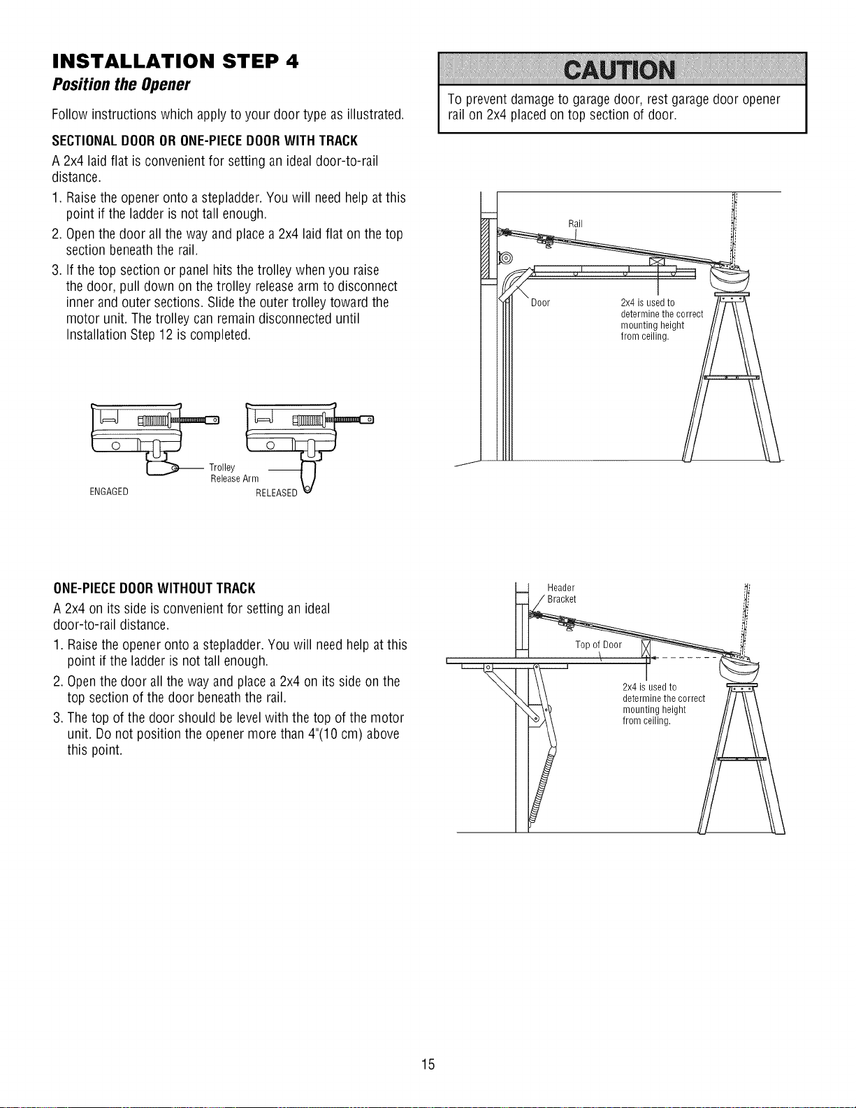
INSTALLATION STEP 4
Positionthe Opener
Follow instructions which apply to your door type as illustrated.
SECTIONALDOORORONE-PIECEDOORWITH TRACK
A 2x4 laid flat is convenient for setting an ideal door-to-rail
distance.
1. Raisethe opener onto a stepladder.You will need help at this
point if the ladder is not tall enough.
2. Openthe door all the way and placea 2x4 laid flat on the top
section beneath the rail.
3. If the top section or panelhits the trolley whenyou raise
the door, pull down on the trolley releasearm to disconnect
inner and outer sections. Slide the outer trolley toward the
motor unit. Thetrolley can remain disconnected until
Installation Step 12is completed.
Trolley
lease
ENGAGED RELEASED_._
To prevent damageto garage door, rest garage door opener
rail on 2x4 placedon top section of door.
Rail
Door 2x4 is used to
determine the correct
mounting height
from ceiling.
ONE-PIECEDOORWITHOUTTRACK
A 2x4 on its side is convenientfor setting an ideal
door-to-rail distance.
1. Raisethe opener onto a stepladder.You will need help at this
point if the ladder is not tall enough.
2. Openthe door all the way and placea 2x4 on its side on the
top section of the door beneaththe rail.
3. The top of the door should be levelwith the top of the motor
unit. Do not position the opener more than 4"(10 cm) above
this point.
Header
Bracket
Top of Door
2x4 is used to
determine the correct
mounting height
from ceiling.
15
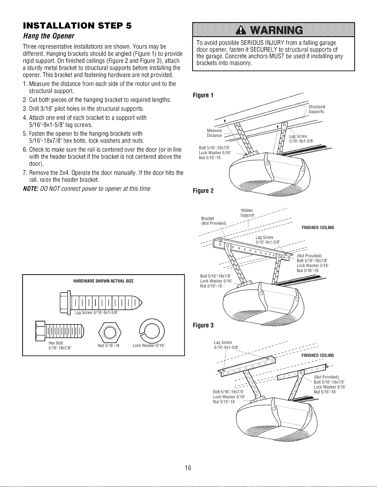
INSTALLATION STEP 5
Hangthe Opener
Threerepresentativeinstallations are shown. Yours may be
different. Hangingbrackets should be angled (Figure1) to provide
rigid support. Onfinished ceilings (Figure 2 and Figure3), attach
a sturdy metal bracketto structural supports before installing the
opener.This bracket and fasteninghardware are not provided.
1. Measurethe distancefrom eachsideof the motor unit to the
structural support.
2. Cut both pieces of the hanging bracketto required lengths.
3. Drill 3/16" pilot holes in the structural supports.
4. Attach one end of eachbracketto a support with
5/16"-9xl-5/8" lag screws.
5. Fastenthe openerto the hanging bracketswith
5/16"-18x7/8" hex bolts, lock washers and nuts.
6. Checkto makesure the rail is centeredover thedoor (or in line
with the headerbracket if the bracketis not centered abovethe
door).
7. Removethe 2x4. Operatethe door manually. If the door hits the
rail, raisethe headerbracket.
NOTE'.DO NOTconnectpower to openerat this time.
Toavoid possible SERIOUSINJURYfrom afalling garage
door opener,fasten it SECURELYto structural supports of
the garage. ConcreteanchorsMUSTbe used if installing any
brackets into masonry.
Figure1
Supports
Measure ",
Distance
Bolt 5/16"-18x7/8"
Lock Washer 5/16"
Nut 5/16"-18
LagScrew
5/16"-9xl-5/8"
Figure2
HARDWARESHOWN ACTUALSIZE
iiii]i I'hL
q Lag Screw 5/16"-9xl-5/8"
5/16"-18x7/8" Nut 5/16"-18
Lock Washer 5/16"
Bolt 5/16"-18x7/8"
Lock Washer 5/16"
Nut 5/16"-18
Figure3
Bolt 5/16"-18x7/8"
Lock Washer 5/16"
Nut 5/16"-18
(Not Provided)
Bolt 5/16"-18x7/8"
Lock Washer 5/16"
Nut 5/16"-18
16
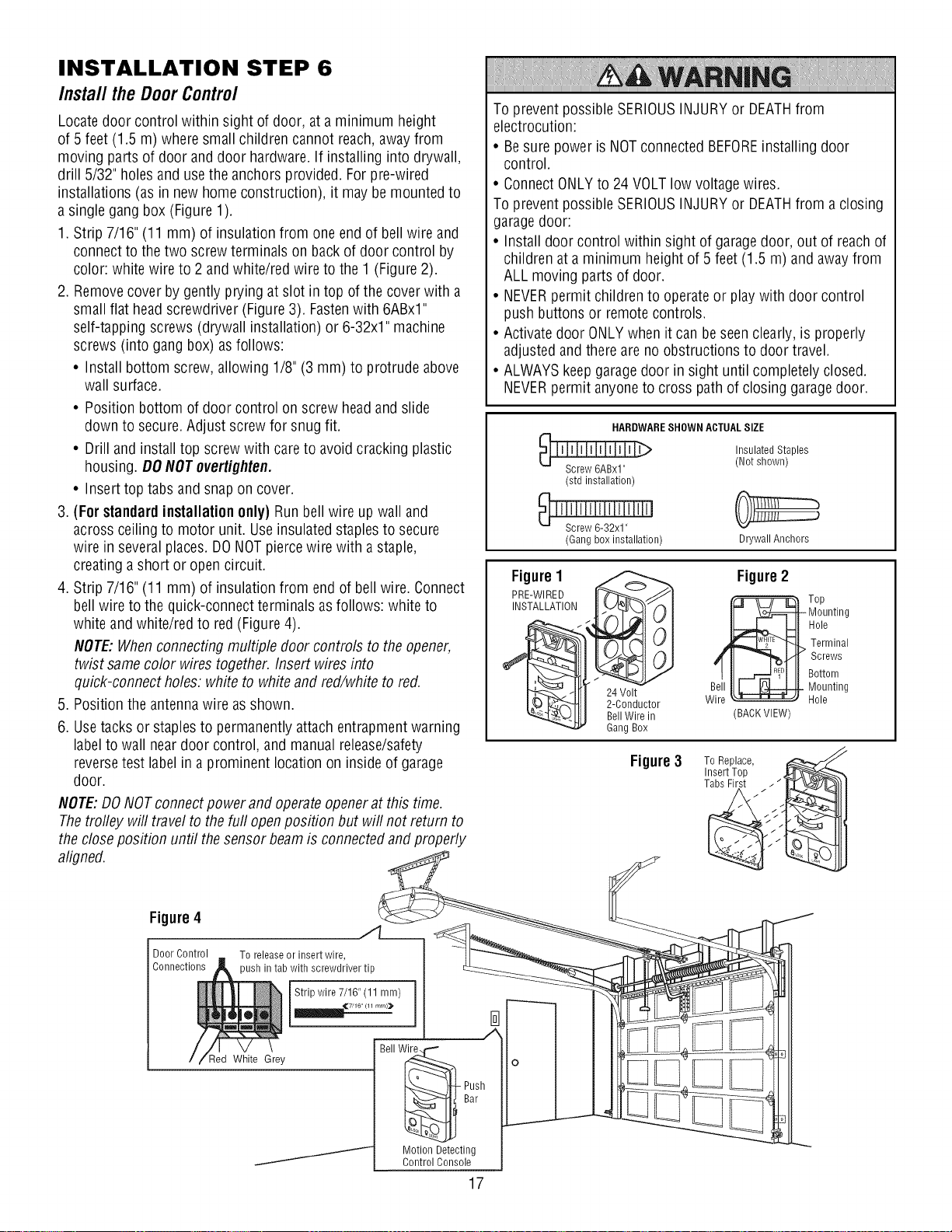
INSTALLATION STEP 6
InstalltheDoorControl
Locate door control within sight of door, ata minimum height
of 5 feet (1.5 m) where small children cannot reach, awayfrom
moving parts of door anddoor hardware.If installing into drywall,
drill 5/32" holesand use the anchorsprovided. Forpre-wired
installations (as in new home construction), it may be mounted to
a single gangbox (Figure 1).
1. Strip 7/16" (11 mm) of insulation from one end of bell wire and
connectto thetwo screwterminals on back of door control by
color: white wire to 2 and white/red wire to the 1 (Figure 2).
2. Removecover by gently prying atslot in top of the cover with a
small flat head screwdriver (Figure3). Fastenwith 6ABxl"
self-tapping screws (drywall installation) or 6-32x1" machine
screws (into gang box) asfollows:
• Install bottom screw, allowing 1/8" (3 mm) to protrude above
wall surface.
• Position bottom of door control on screw headand slide
down to secure. Adjust screw for snug fit.
• Drill and install top screwwith careto avoid cracking plastic
housing. DONOTovertighten.
• Inserttop tabs and snapon cover.
3 (For standardinstallationonly) Run bell wire up wall and
across ceiling to motor unit. Useinsulatedstaplesto secure
wire in severalplaces. DONOTpiercewire with a staple,
creating a short or open circuit.
4. Strip 7/16" (11 mm) of insulation from end of bellwire. Connect
bell wire to the quick-connect terminals asfollows: white to
white andwhite/red to red(Figure4).
NOTE:Whenconnecting multiple door controls to the opener,
twist samecolor wires together. Insert wires into
quick-connectholes: white to whiteand red/white to red.
5. Position theantennawire as shown.
6. Usetacks or staplesto permanentlyattach entrapmentwarning
label to wall near door control, and manualrelease/safety
reversetest labelin a prominent location oninside of garage
door.
NOTE:DONOTconnectpower and operateopenerat this time.
Thetrofley will travel to thefurl openposition but will not return to
the close position until the sensorbeamis connectedand properly
aligned.
To prevent possibleSERIOUSINJURYor DEATHfrom
electrocution:
• Besure power is NOTconnectedBEFOREinstalling door
control.
• ConnectONLYto 24 VOLTlow voltage wires.
To prevent possibleSERIOUSINJURYor DEATHfrom a closing
garagedoor:
• Install door control within sight of garagedoor, out of reach of
children at a minimum height of 5 feet (1.5 m) and away from
ALL moving parts of door.
• NEVERpermit children to operateor play with door control
push buttons or remotecontrols.
• Activatedoor ONLYwhen it can be seenclearly,is properly
adjusted andthere are no obstructions to door travel.
• ALWAYSkeepgaragedoor in sight until completely closed.
NEVERpermit anyoneto cross pathof closing garagedoor.
HARDWARESHOWN ACTUALSIZE
Insulated Staples
(Not shown)
(std installation)
_ ' I 'SJcJrle'_'__'3'2'_1'' '' ' ' J
(Gang box installation)
Figure1
PRE-WIREDIt_JJl
INSTALLATION __
_ 24 Volt
I__- ._._'_t I 2-Conductor
_-Llt I Bell Wire in
Gang Box
Drywall Anchors
Figure2
wB_._ T°p
(BACK VIEW)
Mounting
Hole
Terminal
Screws
Bottom
Mounting
Hole
Figure3 To Replace,
Insert Top ,
Tabs First
Figure4 ./l__
Door Control To release or insert wire,
Connections )ush in tab with screwdriver tip
Strip wire 7/16" (11 mm)
_,_7/16 (11 mrn)_
Red White Grey
J
I
Bell W_ o
Bar .---------
Motion Detecting
Control Console
17
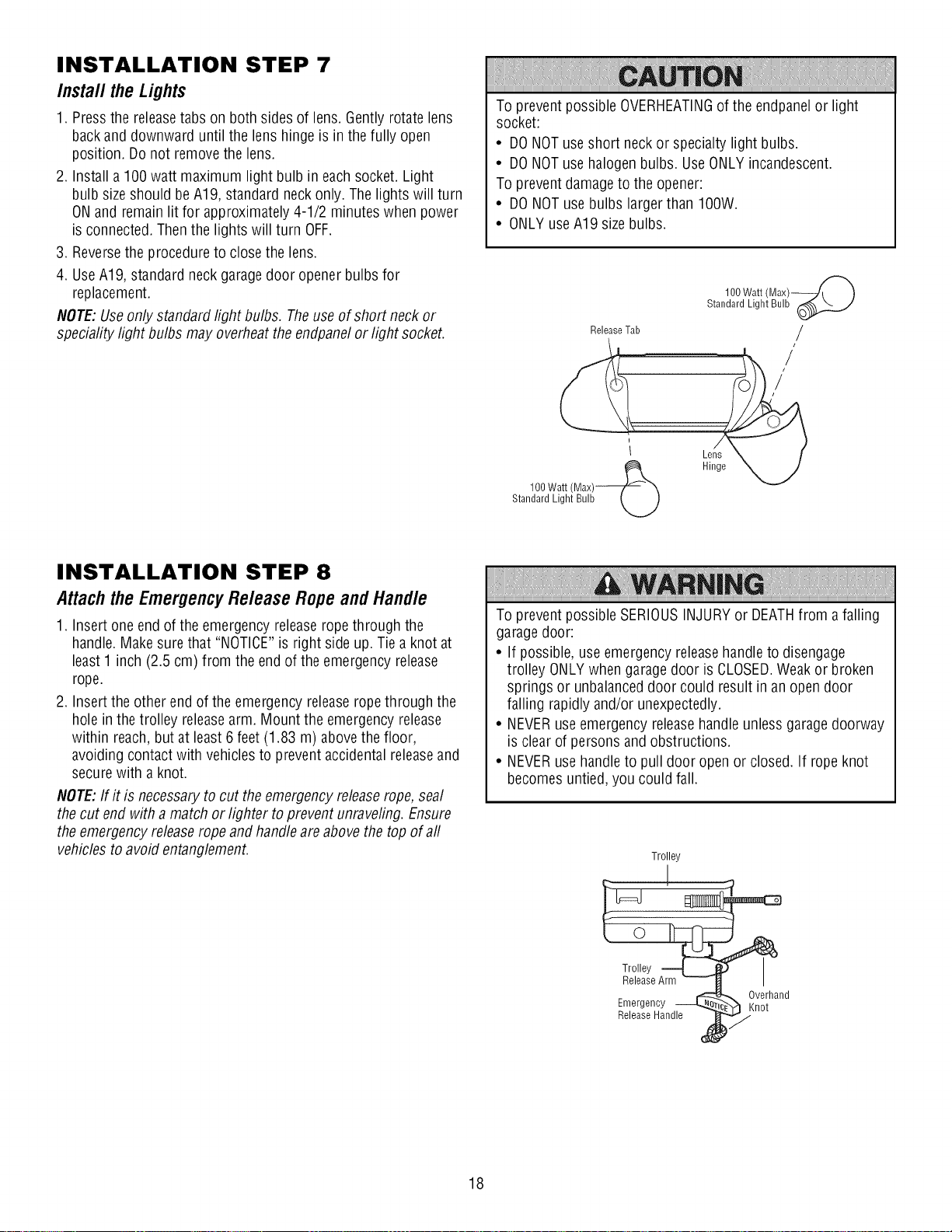
INSTALLATION STEP 7
Install the Lights
1. Pressthe releasetabs on both sides of lens. Gently rotate lens
back and downward until the lens hingeis in the fully open
position. Donot removethe lens.
2. Installa 100watt maximum light bulb in eachsocket. Light
bulb sizeshould beA19, standard neck only.Thelights will turn
ONand remain lit for approximately4-1/2 minuteswhen power
is connected. Thenthe lights will turn OFF.
3. Reversethe procedureto closethe lens.
4. UseA19, standard neck garagedoor opener bulbs for
replacement.
NOTE:Useonly standard light bulbs. Theuseof short neck or
speciafitylight bulbs may overheatthe endpanelorlight socket.
To prevent possibleOVERHEATINGof the endpanelor light
socket:
• DONOTuseshort neck or specialty light bulbs.
• DONOTusehalogen bulbs. Use ONLYincandescent.
To preventdamage to the opener:
• DONOTuse bulbs larger than IOOW.
• ONLYuseA19 sizebulbs.
100Watt (Max)_
Standard Light Bulb_
ReleaseTab /
1 Lens X f
100 Watt (Max)___., _ Hinge "XN_
Standard Light Bulb LJ
INSTALLATION STEP 8
Attach the Emergency Release Rope and Handle
1. Insertone end of the emergencyreleaseropethrough the
handle.Make sure that "NOTICE"is right side up.Tie a knot at
least 1 inch (2.5 cm) from the end of the emergencyrelease
rope.
2. Insertthe other endof the emergencyreleaseropethrough the
hole in thetrolley releasearm. Mount the emergencyrelease
within reach,but at least6 feet (1.83 m) abovethefloor,
avoiding contact with vehiclesto prevent accidental releaseand
securewith a knot.
NOTE:If it is necessaryto cut theemergencyreleaserope, seal
the cut end with a match or lighter to prevent unraveling. Ensure
the emergency releaseropeand handleare above thetop of aft
vehiclestoavoid entanglement.
To prevent possibleSERIOUSINJURYor DEATHfrom a falling
garagedoor:
• If possible, useemergency releasehandleto disengage
trolley ONLYwhen garagedoor is CLOSED.Weakor broken
springs or unbalanceddoor could result in an opendoor
falling rapidly and/or unexpectedly.
• NEVERuseemergency releasehandle unlessgaragedoorway
is clear of persons and obstructions.
• NEVERusehandleto pull door openor closed. If rope knot
becomesuntied, you could fall.
Trolley
ReleaseHandle
Emergency _ _verhandnot
18
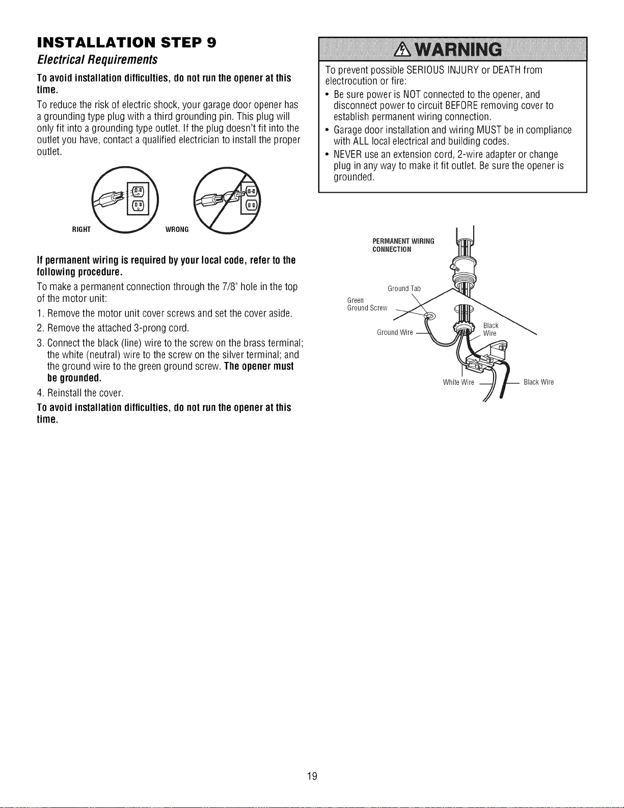
INSTALLATION STEP 9
E/ectrica/Requirements
Toavoidinstallationdifficulties,do notruntheopenerat this
time.
To reduce the risk of electricshock, your garagedoor opener has
a grounding type plug with a third grounding pin. This plug will
only fit into a grounding type outlet. If the plug doesn't fit into the
outlet you have,contacta qualified electricianto install the proper
outlet.
RIGHT_
WRONG
If permanent wiring is requiredby yourlocalcode, refer to the
followingprocedure.
To makea permanent connection through the 7/8" hole in the top
of the motor unit:
1. Removethe motor unit cover screws andset the coveraside.
2. Removethe attached3-prong cord.
3. Connectthe black(line) wire to the screw on the brass terminal;
thewhite (neutral) wire to the screw on the silver terminal; and
the ground wire to the greenground screw. The openermust
be grounded.
4. Reinstallthe cover.
Toavoidinstallationdifficulties,do notruntheopenerat this
time.
To prevent possibleSERIOUSINJURYor DEATHfrom
electrocution or fire:
• Besure poweris NOTconnected to the opener, and
disconnect power to circuit BEFOREremoving cover to
establish permanentwiring connection.
• Garagedoor installation and wiring MUSTbein compliance
with ALL local electrical and building codes.
• NEVERusean extensioncord, 2-wire adapteror change
plug in anyway to make it fit outlet. Besure the opener is
grounded.
PERMANENTWIRING
CONNECTION
Ground Tab
Green
Ground Screw
Ground Wire . Wire
White Wire Black Wire
Black
19

INSTALLATION STEP 10
Install The Protector System®
Thesafety reversingsensormustbe connectedandaligned
correctlybeforethe garagedooropenerwill move in thedown
direction.
IMPORTANTINFORMATIONABOUTTHESAFETYREVERSINGSENSOR
Whenproperly connected andaligned, thesensor will detectan
obstacle in the path of its electronic beam.Thesending eye(with
an amber indicator light) transmits an invisible light beamto
the receiving eye(with a green indicator light). If an obstruction
breaksthe light beamwhile the door is closing, the door will stop
and reverseto full open position, and the openerlights will flash
10 times.
Theunits must be installedinsidethe garageso that the sending
and receivingeyesface eachother acrossthe door, no more than
6"(15 cm) abovethe floor. Eithercan be installedon the left or
right of the door as long as the sun never shines directly into the
receiving eyelens.
Themounting brackets aredesignedto clip ontothe track of
sectionalgarage doors without additional hardware.
Besure power is NOTconnectedto the garagedoor opener
BEFOREinstalling the safety reversingsensor.
To preventSERIOUSINJURYor DEATHfrom a closing garage
door:
• Correctly connect andalign the safety reversing sensor.This
required safety device MUSTNOTbedisabled.
• Install the safety reversingsensor so beam is NOHIGHER
than 6" (15 cm) abovegaragefloor.
If it is necessaryto mount the units on the wall, the brackets must
be securelyfastened to a solid surfacesuch asthe wall framing.
Extensionbrackets (seeAccessories) are availableif needed.If
installing in masonry construction, add a pieceof wood ateach
location to avoiddrilling extraholes in masonry if repositioning is
necessary.
Theinvisible light beam pathmust be unobstructed. No part of
the garagedoor (or door tracks, springs, hinges, rollersor other
hardware) may interrupt the beamwhile the door is closing.
Safety Reversin;211111 7 2"'7ir_i_i ii [f.7;t_;tYZ 2".7"_:: 'g sor
6" (15 cm) max. abovefloor Protection Area 6" (15 cm) max. above floor
Facingthe doorfrom insidethegarage
!o! !÷[ !€
2O
INSTALLINGTHEBRACKETS
Besurepower tothe opener isdisconnected.Install and align
the brackets sothe sensors will face each other acrossthe garage
door, with the beamno higher than 6" (15 cm) abovethe floor.
They may be installed in one of three ways, asfollows.
Garagedoortrack installation (preferred):
1. Slip the curved arms overthe rounded edgeof eachdoor track,
with the curved arms facing the door. Snap into placeagainst
the side of the track. It should lie flush, with the lip hugging the
back edgeof the track, as shown in Figure1.
If your door track will not support the bracketsecurely, wall
installation is recommended.
Wall installation (Figures2 & 3):
1. Placethe bracketagainstthe wall with curved arms facingthe
door. Besurethere is enough clearancefor the sensor beamto
be unobstructed.
2. If additional depth is needed,anextension bracket
(seeAccessories)or wood blocks can be used.
3. Usebracketmounting holes asa template to locate and drill (2)
3/16" diameter pilot holes on the wall at eachside of the door,
no higher than 6" (15 cm) above the floor.
4. Attach bracketsto wall with lag screws (not provided).
5. If using extension bracketsor wood blocks, adjust right and
left assembliesto the same distance out from the mounting
surface. Makesure all door hardwareobstructions are cleared.
Floor installation (Figure 4):
1. Usewood blocks or extension brackets (seeAccessories) to
elevatesensorbrackets sothe lenses will be no higher than
6"(15 cm) abovethe floor.
2. Carefully measureand placeright and left assembliesat the
same distanceout from the wall. Besure all door hardware
obstructions are cleared.
3. Fastento the floor with concrete anchors as shown.
Figure1
DOORTRACKMOUNT (RIGHT SIDE)
i Door
l/I TraC p
_ seneo_r_
acket
Figure2
Figure 3 WALL MOUNT (RIGHT SIDE)
WALLMOUNT (RIGHT SIDE)
Fasten Wood Block to Wall with
Extension
Bracket
(See Accessories)
Indicator
Light
(Not Provided)
Indicator
Light Sensor
(Not Provided)
Lens
(Provided with
Extension Bracket)
Bracket
CarriageBolt
1/4"-20xl/2"
HARDWARESHOWN ACTUALSIZE
Wing Nut
1/4"-20
Insulated Staples
(Not Shown)
21
(Provided with
Extension
Bracket) _J
Figure4
Sensor
Bracket
Indicator
Lens Light
FLOORMOUNT (RIGHT SIDE)
¢i-- ttach with
Concrete Anchors
; (Not Provided)
Indicator
Light
J
Bracket
MOUNTINGANDWIRINGTHESAFETYREVERSINGSENSORS
1. Slide a 1/4"-20xl/2" carriage bolt headinto the slot on each
sensor. Usewing nuts to fastensensors to brackets, with
lenses pointing toward eachother across the door. Besure the
lens is not obstructed by a bracket extension (Figure5).
2. Finger tighten the wing nuts.
3. Runthe wires from both sensors to the opener. Use insulated
staplesto secure wire to wall and ceiling.
4. Strip 7/16" (11 mm) of insulation from each set of wires.
Separatewhite and white/black wires sufficiently to connect to
the opener quick-connect terminals. Twist like colored wires
together. Insert wires into quick-connect holes:white to white
and white/black to grey (Figure 6).
ALIGNINGTHESAFETYREVERSINGSENSORS
1. Plug in the opener. The indicator lights in both the sending and
receiving eyeswill glow steadilyif wiring connections and
alignment are correct.
Thesending eyeamber indicator light will glow regardlessof
alignment or obstruction. If the green indicator light in the
receiving eyeis off, dim, or flickering (and the invisible light beam
path is not obstructed), alignment is required.
2. Loosenthe sending eyewing nut and readjust, aiming directly
at the receiving eye.Lock in place.
3. Loosenthe receiving eye wing nut and adjust sensor until it
receivesthe sender's beam. Whenthe green indicator light
glows steadily, tighten the wing nut.
Figure5
Wing Nut
CarriageBolt
1/4"-20xl/2"
TROUBLESHOOTINGTHESAFETYREVERSINGSENSORS
1. If the sending eyeindicator light does not glow steadily after
installation, checkfor:
• Electric powerto the opener.
• A short inthe white or white/black wires. Thesecanoccur at
staples, or at opener connections.
• Incorrect wiring between sensors and opener.
• A broken wire.
2. If the sending eye indicator light glows steadily but the
receiving eyeindicator light doesn't:
• Checkalignment.
• Checkfor an open wire to the receiving eye.
3. If the receiving eyeindicator light is dim, realigneither sensor.
NOTE:Whenthe invisible beam path is obstructed ormisaligned
while the door is closing, the door will reverse. If the door is
already open, it will not close. The openerlights will blink 10
times. Seepage 20.
Figure6
Bell Wire Finished
, I]r ;'ff
-- Ceiling --
Connect Wire to
Quick-Connect Terminals
2. Twist like colored
wires together
3. To release or insert
wire, push intab with
screwdriver tip
- Protection Area
Safety Reversing Sensor
Safety Reversing Sensor
22
Red White Grey
Quick-Connect Terminals
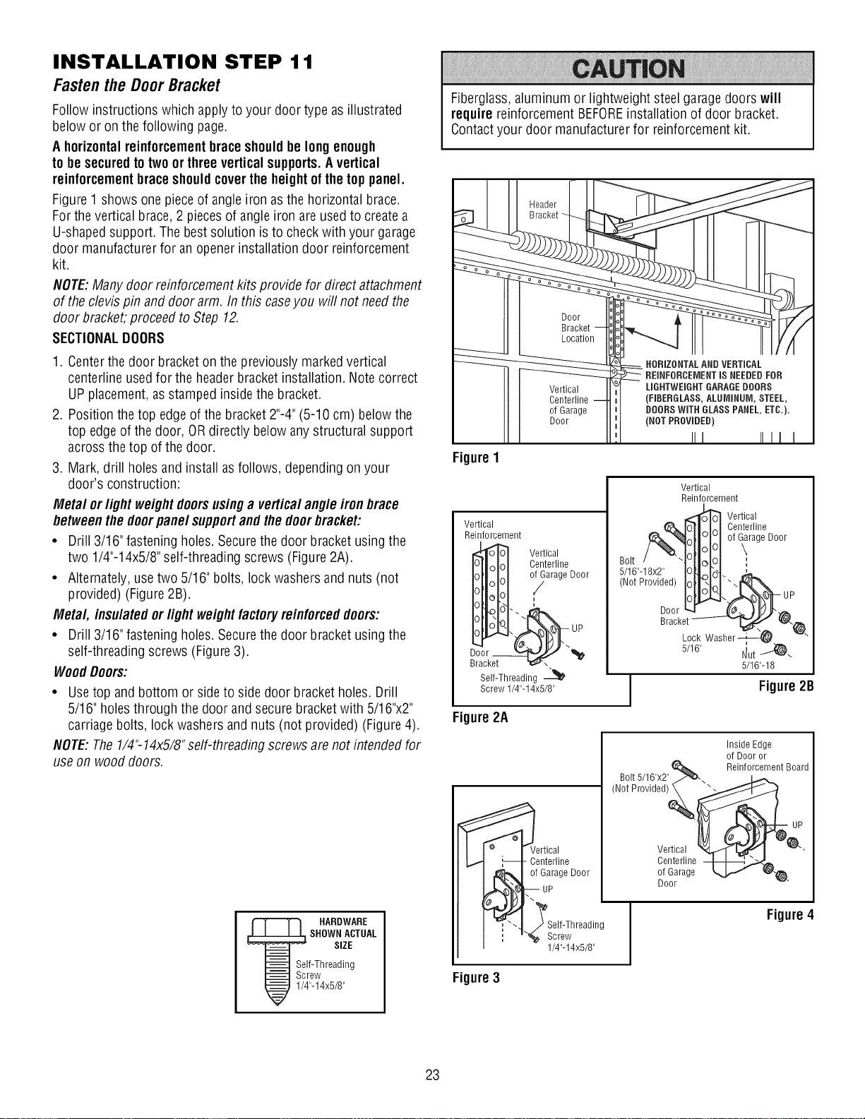
INSTALLATION STEP 11
Fastenthe DoorBracket
Follow instructions which applyto your door type as illustrated
below or on the following page.
Ahorizontalreinforcementbraceshouldbe longenough
tobe securedto twoorthree verticalsupports.A vertical
reinforcementbraceshouldcoverthe heightofthe top panel.
Figure1 shows one pieceof angle iron as the horizontal brace.
Forthe vertical brace, 2 piecesof angleiron are usedto createa
U-shapedsupport. The best solution is to checkwith your garage
door manufacturer for an openerinstallation door reinforcement
kit.
NOTE:Many door reinforcement kits provide for direct attachment
of theclevis pin and door arm. In this caseyou will not needthe
door bracket, proceedto Step 12.
SECTIONALDOORS
Fiberglass,aluminum or lightweight steel garage doors will
requirereinforcement BEFOREinstallation of door bracket.
Contactyour door manufacturer for reinforcement kit.
Door
Bracket
Location
1. Centerthe door bracketon the previously markedvertical
centerline usedfor the headerbracketinstallation. Note correct
UPplacement, as stamped inside the bracket.
2. Position thetop edgeof the bracket 2"-4"(5-10 cm) belowthe
top edge of the door, ORdirectly below anystructural support
acrossthe top of the door.
3. Mark, drill holesand install as follows, dependingon your
door's construction:
Metal or light weight doorsusinga verticalangleiron brace
betweenthe doorpanel supportandthe doorbracket:
• Drill 3/16" fastening holes. Securethedoor bracketusing the
two 1/4"-14x5/8" self-threading screws (Figure2A).
• Alternately,usetwo 5/16" bolts, lock washersand nuts (not
provided) (Figure2B).
Metal, insulatedor light weightfactoryreinforceddoors:
• Drill 3/16" fastening holes. Securethedoor bracketusing the
self-threading screws (Figure3).
WoodDoors:
• Usetop and bottom or side to side door bracketholes. Drill
5/16" holesthrough the door and secure bracketwith 5/16"x2"
carriagebolts, lock washers and nuts (not provided) (Figure4).
NOTE:The1/4"-14x5/8"self-threading screws are not intendedfor
use on wooddoors.
Figure1
Vertical
Reinforcement
Self-Threading -_
Screw 1/4"-14x5/8"
Figure2A
Vertical
Centerline
of Garage
Door
Vertical
Centerline
i
o_arage Door
HORIZONTALANDVERTICAL
REINFORCEMENTISNEEDEDFOR
LiGHTWEiGHTGARAGEDOORS
(FIBERGLASS, ALUMINUM, STEEL,
DOORSWiTH GLASSPANEL, ETC.).
(NOT PROVIDED)
III IIII
Vertical
Reinforcement
,_ Vertical
IoTl_LI Centerline
1ollololof ?rage Door
Bolt/ TIIolOl :
5/16"-18x2" IOILIbl. -
(NotProvided) HI?N
5/16" I_ut _-
5/16"-18
J Figure2B
Inside Edge
of Door or
Bolt5/16"x2"
(NotProvided)
Reinforcement Board
HARDWARE
SHOWNACTUAL
SIZE
If-Threading
rew
"-14x5/8"
23
Figure3
,_rtical
Centerline
of Garage Door
UP
Screw
1/4"-14x5/8"
Vertical
Centerline
of Garage
Door
Figure4
 Loading...