

Page 1
Owner's Manual/Manual Del Propietario
II:RRFTSMRNI
1/2 HP
315MNz GARAGE DOOR OPENER
ABRIDOR DE PUERTA DE COCHERA DE 315MN=
For Residential Use Only/Solo para uso residencial
Model/Modelo • 139.53914D
Read and follow all safety rules
and operating instructions before
first use of this product.
Fasten the manual near the garage
door after installation.
Periodic checks of the opener are
required to ensure safe operation.
rlq
m
Leer y seguir todas las reglas de _,_
seguridad y las instrucciones de Z=
operacion antes de usar este 0
producto por primera vez. r--
Guardar este manual cerca de la
puerta de la cochera.
Se deben realizar revisiones
periodicas del abridor de puertas
para asegurar su operacion
segura.
Sears, Roebuck and Co., Hoffman Estates, IL 60179 U.S.A
www.sears.com/craftsman
Page 2
TABLE OF CONTENTS
Introduction 2- 7
Safety symbol and signal word review ........................ 2
Preparing your garage door ........................................ 3
Tools needed ............................................................... 3
Planning .................................................................. 4-5
Carton inventory .......................................................... 6
Hardware inventory ..................................................... 7
Assembly 8.11
Assemble the rail and install the trolley ...................... 8
Fasten the rail to the motor unit and
Install the idler pulley ................................................... 9
Install the belt and attach the belt cap retainer ......... 10
Set the tension .......................................................... 11
Installation 11-26
Installation safety instructions .................................... 11
Determine the header bracket location ..................... 12
Install the header bracket .......................................... 13
Attach the rail to the header bracket ......................... 14
Position the opener ................................................... 15
Hang the opener ....................................................... 16
Install the door control ............................................... 17
Install the lights ......................................................... 18
Attach the emergency release rope and handle ....... 18
Electrical requirements .............................................. 19
Install The Protector System ®.............................. 20-22
Fasten the door bracket ....................................... 23-24
Connect the door arm to the trolley ..................... 25-26
Adjustment 27-29
Adjust the travel limits ............................................... 27
Adjust the force ......................................................... 28
Test the safety reversal system ................................. 29
Test The Protector System ®...................................... 29
Operation 30-34
Operation safety instructions ..................................... 30
Using your garage door opener ................................ 30
Using the wall-mounted Door Control ....................... 31
To open the door manually ........................................ 31
Care of your garage door opener .............................. 32
Having a problem? .................................................... 33
Diagnostic chart ......................................................... 34
Programming 35-36
To add or reprogram a hand-held remote control .....35
To erase all codes ..................................................... 35
3-Function Remotes .................................................. 35
To add, reprogram or change
a Keyless Entry PIN .................................................. 36
Repair Parts 37.38
Rail assembly parts ................................................... 37
Installation parts ........................................................ 37
Motor unit assembly parts ......................................... 38
Accessories 39
Warranty 39
Repair Parts & Service Back Cover
INTRODUCTION
Safety Symbol
and Signal Word Review
This garage door opener has been designed and tested to offer safe service provided it is installed, operated,
maintained and tested in strict accordance with the instructions and warnings contained in this manual.
When you see these Safety Symbols and Signal
Words on the following pages, they will alert you to
Mechanical
Electrical
the possibility of serious injury or death if you do
not comply with the warnings that accompany them.
The hazard may come from something mechanical
or from electric shock. Read the warnings carefully.
When you see this Signal Word on the following
pages, it will alert you to the possibility of damage to
your garage door and/or the garage door opener if
you do not comply with the cautionary statements
that accompany it. Read them carefully.
Page 3
Preparing your garage door
Before you begin:
• Disable locks.
• Remove any ropes connected to garage door.
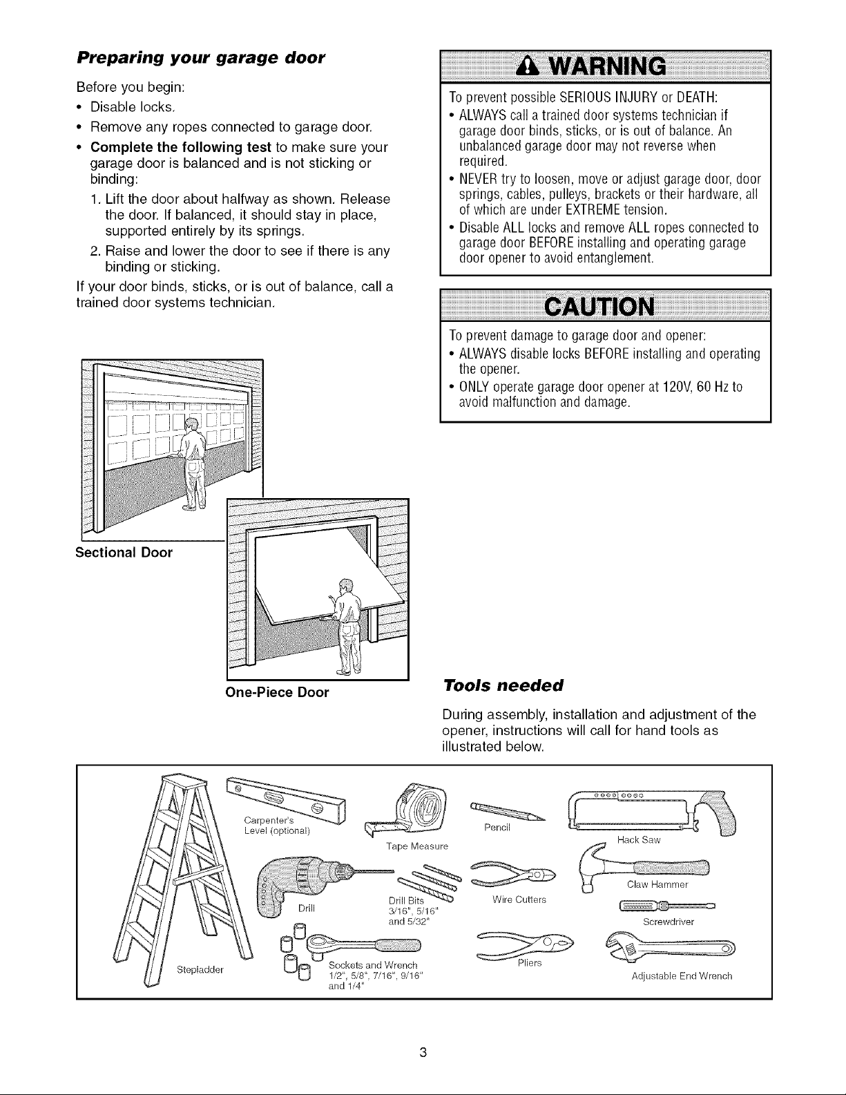
• Complete the following test to make sure your
garage door is balanced and is not sticking or
binding:
1. Lift the door about halfway as shown. Release
the door. If balanced, it should stay in place,
supported entirely by its springs.
2. Raise and lower the door to see if there is any
binding or sticking.
If your door binds, sticks, or is out of balance, call a
trained door systems technician.
To prevent possible SERIOUSINJURYor DEATH:
• ALWAYScall atrained door systems technician if
garage door binds, sticks, or is out of balance.An
unbalancedgarage door may not reverse when
required.
• NEVERtry to loosen,moveor adjust garage door,door
springs, cables, pulleys, brackets ortheir hardware,all
of which are under EXTREMEtension.
• Disable ALLlocks and removeALL ropes connectedto
garage door BEFOREinstalling and operating garage
door opener to avoid entanglement.
To prevent damageto garage door andopener:
• ALWAYSdisable locks BEFOREinstalling and operating
the opener
• ONLYoperategaragedoor opener at 120V,60 Hzto
avoid malfunction and damage
Sectional Door
One-Piece Door
Level (optional)
Drill
Tape Measure
3/16", 5/16'
and 5/32'
Tools needed
During assembly, installation and adjustment of the
opener, instructions will call for hand tools as
illustrated below.
Pencil
Hack Saw
Claw Hammer
Wire Cutters
Screwdriver
Stepladder
and 1/4"
Adjustable End Wrench
Page 4
Planning
Identify the type and height of your garage door.
Survey your garage area to see if any of the
conditions below apply to your installation. Additional
materials may be required. You may find it helpful to
refer back to this page and the accompanying
illustrations as you proceed with the installation of
your opener.
Depending on your requirements, there are several
installation steps which may call for materials or
hardware not included in the carton.
• Installation Step 1 - Look at the wall or ceiling
above the garage door. The header bracket must
be securely fastened to structural supports.
• Installation Step 5 - Do you have a finished ceiling
in your garage? If so, a support bracket and
additional fastening hardware may be required.
• Installation Step 10- Depending upon garage
construction, extension brackets or wood blocks
may be needed to install sensors.
• Installation Step 10 -Alternate floor mounting of
the safety reversing sensor will require hardware
not provided.
Do you have an access door in addition to the
garage door? If not, Model 53702 Emergency Key
Release is required. See Accessories page.
Look at the garage door where it meets the floor.
Any gap between the floor and the bottom of the
door must not exceed 1/4" (6 ram). Otherwise, the
safety reversal system may not work properly. See
Adjustment Step 3. Floor or door should be
repaired.
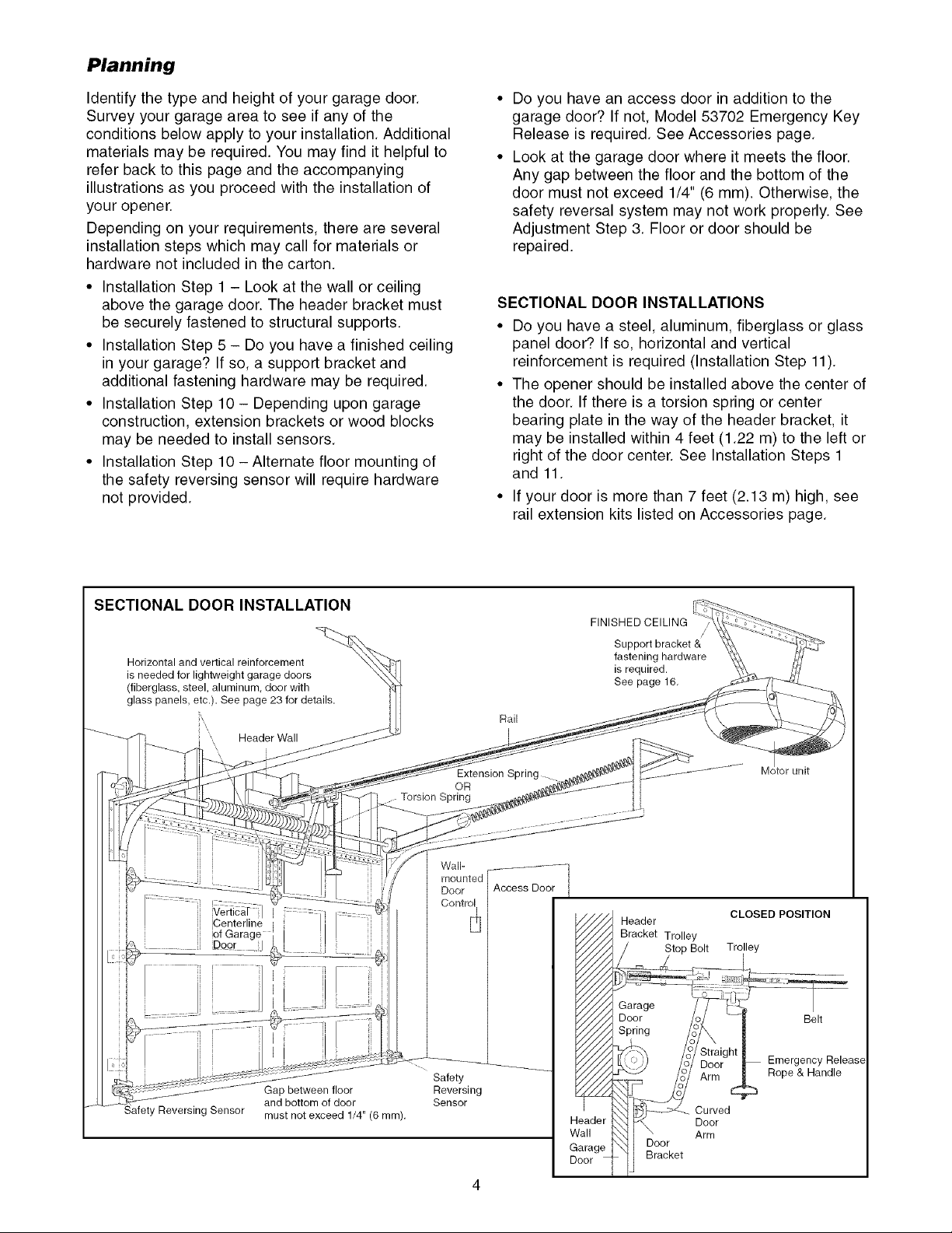
SECTIONAL DOOR INSTALLATIONS
• Do you have a steel, aluminum, fiberglass or glass
panel door? If so, horizontal and vertical
reinforcement is required (Installation Step 11).
• The opener should be installed above the center of
the door. If there is a torsion spring or center
bearing plate in the way of the header bracket, it
may be installed within 4 feet (1.22 m) to the left or
right of the door center. See Installation Steps 1
and 11.
• If your door is more than 7 feet (2.13 m) high, see
rail extension kits listed on Accessories page.
SECTIONAL DOOR INSTALLATION
Horizontal and vertical reinforcement
is needed for lightweight garage doors
(fiberglass, steel, aluminum, door with
glass panels, etc.). See page 23 for details.
\
' Header Wall
lCenterline i :: I...........
of Garage 'l I I
Door I_L_
Gap between floor
and bottom of door
must not exceed 1/4" (6 ram).
.... Torsion Spring
Wall-
mounted
Door
Control
Safety
Reversing
Sensor
Rail
Extension Spring
OR
Access Door
FINISHED CEILING
Support bracket &
fastening hardware
is required.
See page 16.
Header
Bracket Trolley
____Bolt Trolley
i _s_d
_/_ Garage /_7
F////A Door o/
_ Spring /_:
_////)_J /2/ D,
Header _ _ Door
Wall i\\_ F \ Arm
Garage HI Door
/
Straight !
Door_ _ Emergency Release
Arm _ Rope & Handle
Curved
Dooi_ ]l _a_t
unit
CLOSED POSITION
! Be,,
Page 5
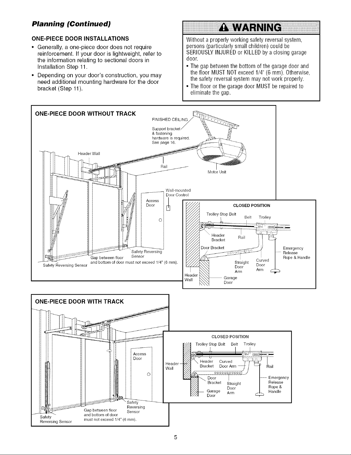
Planning (Continued)
ONE-PIECE DOOR INSTALLATIONS
• Generally, a one-piece door does not require
reinforcement. If your door is lightweight, refer to
the information relating to sectional doors in
Installation Step 11.
• Depending on your door's construction, you may
need additional mounting hardware for the door
bracket (Step 11).
ONE-PIECE DOOR WITHOUT TRACK
FINISHED
& fastening
hardware is required.
See page t6,
_-'_ HeaderWall
/
Access
Door
I
Rail
Wail-mounted
Door Control
Without a properly working safetyreversal system,
persons (particularly small children) could be
SERIOUSLYINJUREDor KILLEDby a closing garage
door.
• Thegap betweenthe bottom of the garage door and
the floor MUSTNOTexceed 1/4"(6 mm). Otherwise,
the safety reversal system maynot work properly.
• Thefloor or the garage door MUST be repairedto
eliminate the gap.
Motor Unit
CLOSED POSITION
Trolley Stop Bolt
Belt Trolley
drt1 I
Gap between floor
Safety Reversing Sensor
and bottom of door must not exceed 1/4" (6 mm).
ONE-PIECE DOOR WITH TRACK
J Safety and bottom of door
Reversing Sensor must not exceed 1/4" (6 turn),
Gap between floor Sensor
Safety Reversing
Sensor
let
Reversing
Header
Wall
_eader
Vail
Trolley Stop Bolt Belt Trolley
J_-Head_r Curved
Bracket Door Arm _- /
idh,. °°°°°°l°°°°°)_
_////'_ Bracket Straight
"//A Door
///"_1_ Garage Arm
_/I Door
Garage
Door
CLOSED POSiTiON
Door I
Straight
Door Door
Arm Arm
I --
-- Emergency
Rail
Release
Rope &
Handle
Emergency
Release
Rope & Handle
Page 6

Carton Inventory
Your garage door opener is packaged in one carton
which contains the motor unit and all parts illustrated
below. Accessories will depend on the model
purchased. If anything is missing, carefully check the
SECURITY,l, _
3-Function Remote Control (2)
Premium Control Console
Belt Cap Retainer
packing material. Parts may be stuck in the foam.
Hardware for assembly and installation is shown on
the next page. Save the carton and packing material
until installation and adjustment is complete.
Trolley
SECURITY+ ®
Keyless Entry
Rail
Center/Back
Sections
Idler Pulley
Rail
Fron! (header) /_¢v/_
j
Safety Sensor
Bracket (2)
Motor Unit with 2 Light Lenses
Header Bracket
(2) Safety Reversing Sensors
(1 Sending Eye and 1 Receiving Eye)
with 2-Conductor White & White/Black
Bell Wire attached
Belt
Door Bracket
"U" Bracket
Curved Door
Arm Section
2-Conductor Bell Wire
White & White/Red
Safety Labels
and
Literature
Hanging Brackets
Straight Door
Arm Section
Page 7
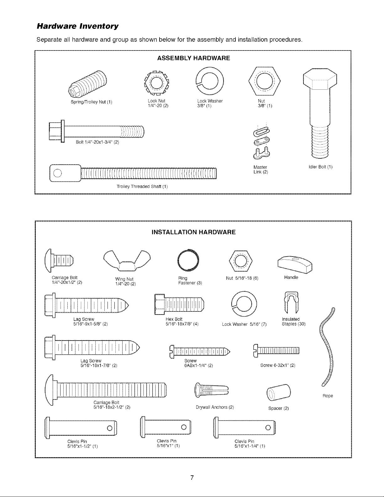
Hardware Inventory
Separate all hardware and group as shown below for the assembly and installation procedures.
ASSEMBLY HARDWARE
Spring/Trolley Nut (1)
Bolt 1/4"-20xl-3/4" (2)
Carriage Bolt
1/4"-20xl/2" (2)
Lock Nut Lock Washer Nut
1/4"-20 (2) 3/8" (1) 3/8" (1)
Trolley Threaded Shaft (1)
INSTALLATION HARDWARE
Wing Nut
1/4"-20 (2)
O
Ring
Fastener (3)
©
Nut 5/16"-18 (6)
Master
Link (2)
i
Idler Bolt (1)
Handle
Lag Screw
5/16"-9xt -5/8" (2)
Lag Screw
5/16"-18xl -7/8" (2)
Clevis Pin
5/16"xl -1/2" (1)
Carriage Bolt
5/16"-18x2-1/2" (2)
o]
©
Hex Bolt
5/16"- 18x7/8" (4)
Screw
6ABxl-1/4" (2)
Drywall Anchors (2)
Clevis Pin Clevis Pin
5/18"x1" (1) 5/16"x1-1/4" (1)
Lock Washer 5/16" (7)
Insulated
Staples (30)
Screw 6-32x1" (2)
Rope
Spacer (2)
Page 8

ASSEMBLY STEP 1
Assemble the Rail & Install the Trolley
To avoid installation difficulties, do not run the
garage door opener until instructed to do so.
The front rail has a cut out "window" at the door end
(see illustration). The hole above this window is
larger on the top of the rail than on the bottom. A
smaller hole 3-1/2" (8.9 cm) away is close to the rail
edge. Rotate the back rail so it has a similar hole
close to the opposite edge, about 4-3/4" (12 cm)
from the far end.
1. Remove the straight door arm and hanging
bracket packaged inside the front rail and set
aside for Installation Step 5 and 12. NOTE: To
prevent INJURY while unpacking the rail carefully
remove the straight door arm stored within the rail
section.
2. Align the rail sections on a flat surface as shown
and slide the tapered ends into the larger ones.
Tabs along the side will lock into place.
To prevent INJURYfrom pinching, keephandsand
fingers awayfrom the joints while assembling the rail.
3. Place the motor unit on packing material to protect
the cover, and rest the back end of the rail on top.
For convenience, put a support under the front
end of the rail.
4. As a temporary stop, insert a screwdriver into the
hole 10" (25 cm) from the front end of the rail, as
shown.
5. Check to be sure there are 4 plastic wear pads
inside the inner trolley. If they became loose
during shipping, check all packing material. Snap
them back into position as shown.
6. Slide the trolley assembly along the rail from the
back end to the screwdriver.
End
End
Trolley
_ered
End
End
ack Rails
(TO MOTOR UNIT)
)ered
Outer Trolley
Inner Trolley
\
Wear Pads
Page 9
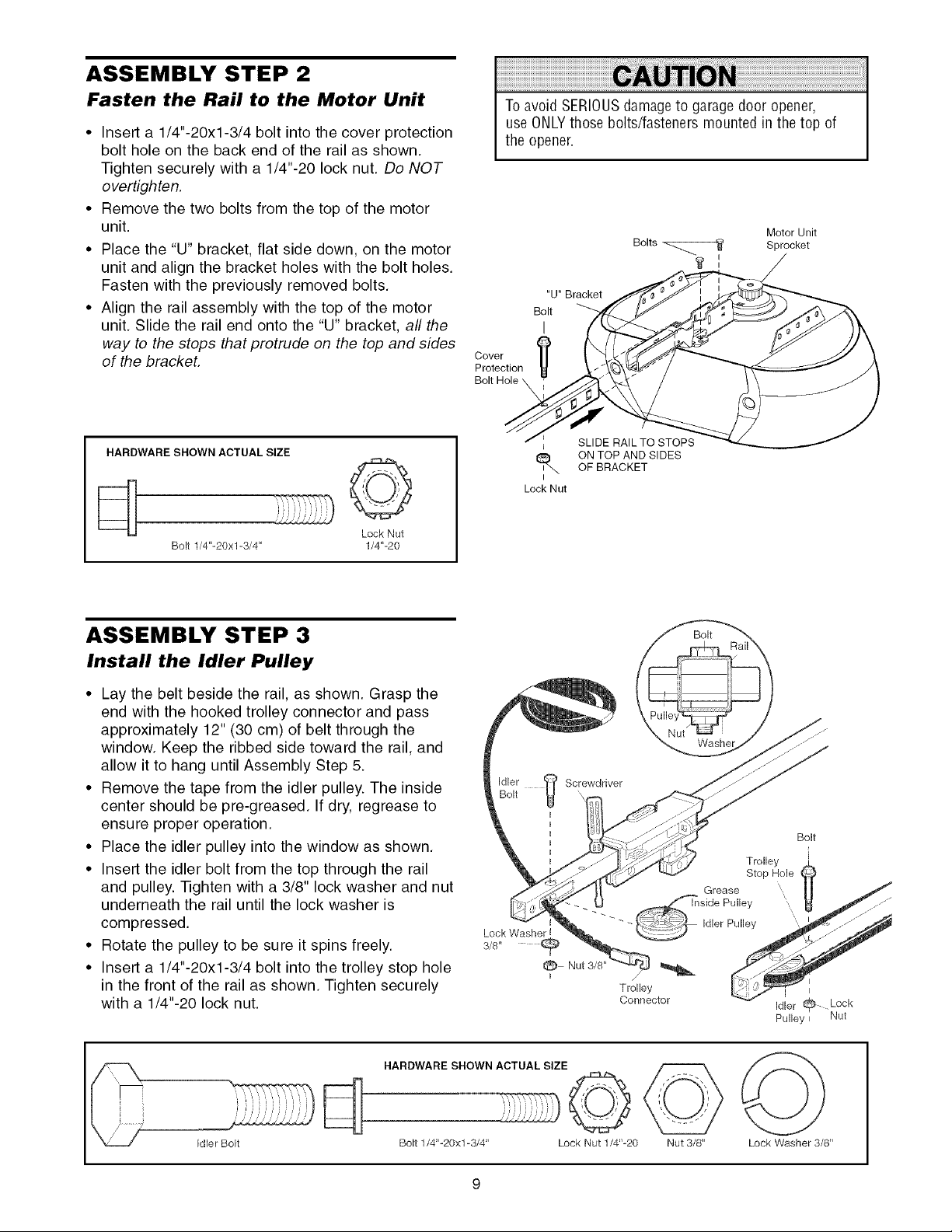
ASSEMBLY STEP 2
Fasten the Rail to the Motor Unit
• Insert a 1/4"-20xl-3/4 bolt into the cover protection
bolt hole on the back end of the rail as shown.
Tighten securely with a 1/4"-20 lock nut. Do NOT
overtighten.
• Remove the two bolts from the top of the motor
unit
• Place the "U" bracket flat side down, on the motor
unit and align the bracket holes with the bolt holes.
Fasten with the previously removed bolts.
• Align the rail assembly with the top of the motor
unit. Slide the rail end onto the "U" bracket, all the
way to the stops that protrude on the top and sides
of the bracket.
HARDWARE SHOWN ACTUAL SIZE
©
Bolt 1/4"-20xl-3/4" 1/4'L20
Lock Nut
To avoid SERIOUSdamageto garagedoor opener,
use ONLYthose bolts/fasteners mounted in the top of
the opener.
"U" Bracket
Bolt
I
Cover
Protection
Bolt Hole _
SLIDE RAIL TO STOPS
I
ON TOP AND SIDES
OF BRACKET
I
Lock Nut
Motor Unit
Sprocket
ASSEMBLY STEP 3
Install the Idler Pulley
• Lay the belt beside the rail, as shown. Grasp the
end with the hooked trolley connector and pass
approximately 12" (30 cm) of belt through the
window. Keep the ribbed side toward the rail, and
allow it to hang until Assembly Step 5.
• Remove the tape from the idler pulley. The inside
center should be pre-greased. If dry, regrease to
ensure proper operation.
• Place the idler pulley into the window as shown.
• Insert the idler bolt from the top through the rail
and pulley. -iqghten with a 3/8" lock washer and nut
underneath the rail until the lock washer is
compressed.
• Rotate the pulley to be sure it spins freely.
• Insert a 1/4"-20xl-3/4 bolt into the trolley stop hole
in the front of the rail as shown. Tighten securely
with a 1/4"-20 lock nut.
HARDWARE SHOWN ACTUAL SIZE
Connector
Bolt
Idler _ Lock
Pulley _ Nut
Idler Bolt
©
Bolt 1/4'L20x1-3/4" Lock Nut 1/4'L20 Nut 3/8" Lock Washer 3/8"
Page 10
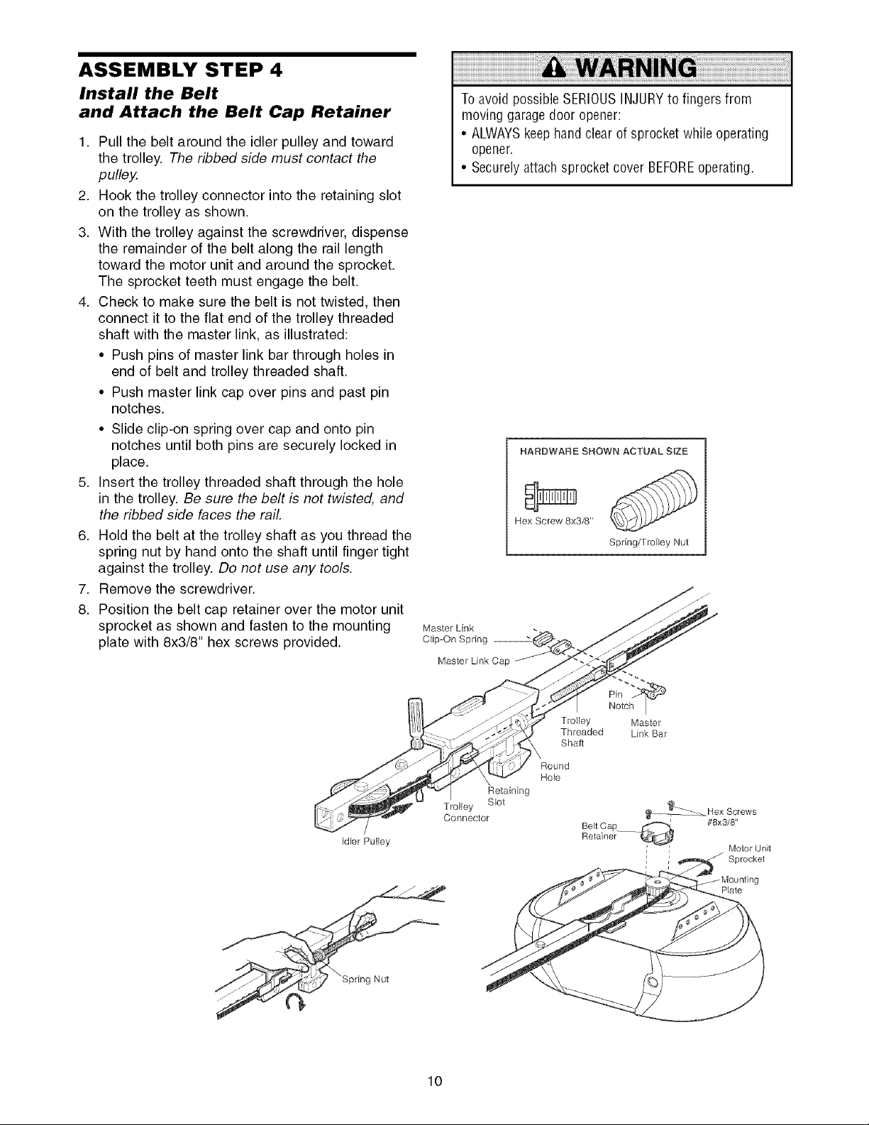
ASSEMBLY STEP 4
Install the Belt
and Attach the Belt Cap Retainer
1. Pull the belt around the idler pulley and toward
the trolley. The ribbed side must contact the
pulley.
2. Hook the trolley connector into the retaining slot
on the trolley as shown.
3. With the trolley against the screwdriver, dispense
the remainder of the belt along the rail length
toward the motor unit and around the sprocket.
The sprocket teeth must engage the belt.
4. Check to make sure the belt is not twisted, then
connect it to the flat end of the trolley threaded
shaft with the master link, as illustrated:
• Push pins of master link bar through holes in
end of belt and trolley threaded shaft.
• Push master link cap over pins and past pin
notches.
• Slide clip-on spring over cap and onto pin
notches until both pins are securely locked in
place.
5. Insert the trolley threaded shaft through the hole
in the trolley. Be sure the belt is not twisted, and
the ribbed side faces the rail.
6. Hold the belt at the trolley shaft as you thread the
spring nut by hand onto the shaft until finger tight
against the trolley. Do not use any tools.
7. Remove the screwdriver.
8. Position the belt cap retainer over the motor unit
sprocket as shown and fasten to the mounting
plate with 8x3/8" hex screws provided.
To avoid possible SERIOUSINJURYto fingers from
moving garage door opener:
• ALWAYSkeephand clear of sprocket while operating
opener.
• Securelyattach sprocket cover BEFOREoperating.
HARDWARE SHOWN ACTUAL SIZE
Hex Screw 8x3/8"
Spring/Trolley Nut
Master Link
Clip-On Spring
Master Link Cap
idler Pulley
Pin
Trolley Master
Threaded Link Bar
Shaft
Round
Hole
Retaining
Trolley Slot
Connector
///
Notc_
_- Hex Screws
Be_t Cap ___ #8x3/8
Retainer
i / Sprocket
Motor Unit
Plate
10
Page 11
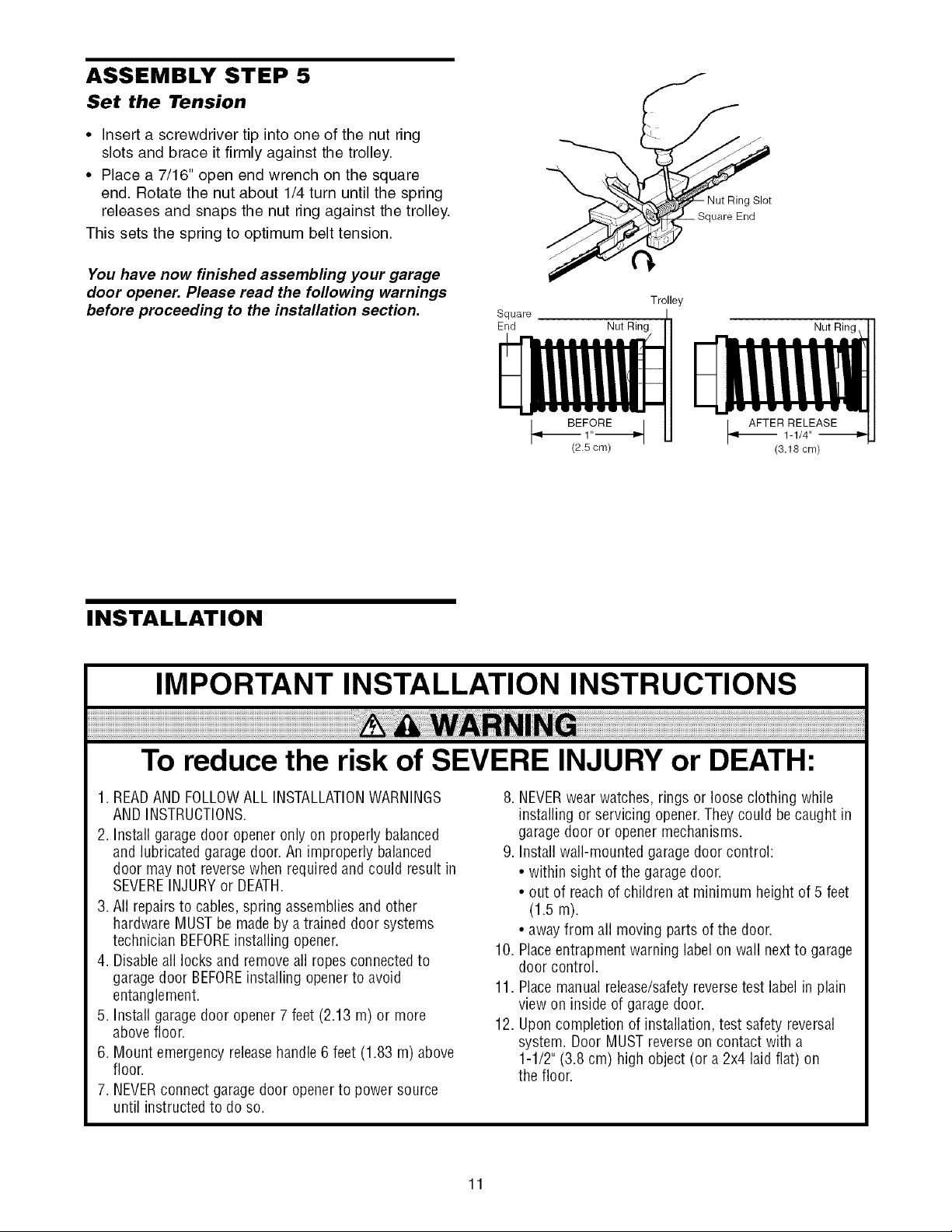
ASSEMBLY STEP 5
Set the Tension
• Insert a screwdriver tip into one of the nut ring
slots and brace it firmly against the trolley.
• Place a 7/16" open end wrench on the square
end. Rotate the nut about 1/4 turn until the spring
releases and snaps the nut ring against the trolley.
This sets the spring to optimum belt tension.
You have now finished assembling your garage
door opener. Please read the following warnings
before proceeding to the installation section.
Square
End
Trolley
Nut Ring Nut Rin(
INSTALLATION
IMPORTANT INSTALLATION INSTRUCTIONS
To reduce the risk of SEVERE INJURY or DEATH:
1. READAND FOLLOWALL INSTALLATIONWARNINGS
AND INSTRUCTIONS.
2. Install garage door openeronly on properly balanced
and lubricated garage door. An improperly balanced
door may not reversewhen required and could result in
SEVEREINJURYor DEATH.
3. All repairs to cables,spring assembliesand other
hardwareMUST be madeby atrained door systems
technician BEFOREinstalling opener.
4. Disableall locks and removeall ropesconnected to
garage door BEFOREinstalling opener to avoid
entanglement.
5. Install garage door opener7 feet (2.13 m) or more
above floor.
6. Mount emergency releasehandle 6 feet (1.83 m) above
floor.
7. NEVERconnect garage door openerto power source
until instructed to do so.
8. NEVERwearwatches, rings or loose clothing while
installing or servicing opener.They could be caught in
garage door or opener mechanisms.
9. Install wall-mounted garage door control:
• within sight of the garage door.
• out of reach of children at minimum height of 5 feet
(1.5 m).
• awayfrom all moving parts of the door.
10. Placeentrapment warning label on wall next to garage
door control.
11. Placemanual release/safetyreversetest label in plain
view on inside of garage door.
12. Uponcompletion of installation, test safety reversal
system. Door MUST reverseon contact with a
1-1/2" (3.8 cm) high object(or a 2x4 laid flat) on
the floor.
11
Page 12
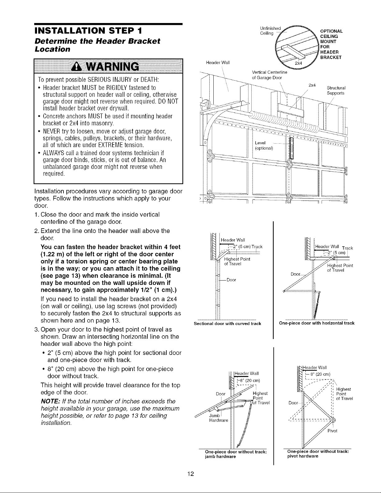
INSTALLATION STEP 1
Determine the Header Bracket
Location
Toprevent possible SERIOUSINJURYor DEATH:
• Headerbracket MUSTbe RIGIDLYfastenedto
structural support on headerwall or ceiling, otherwise
garagedoor might not reversewhen required. DONOT
install headerbracket over drywall.
• Concreteanchors MUST be usedif mounting header
bracket or 2x4 into masonry.
• NEVERtry to loosen, move or adjust garagedoor,
springs, cables, pulleys, brackets,or their hardware,
all of which are under EXTREMEtension.
• ALWAYScall a trained door systemstechnician if
garagedoor binds, sticks, or is out of balance.An
unbalancedgarage door might not reversewhen
required.
Installation procedures vary according to garage door
types. Follow the instructions which apply to your
door.
1. Close the door and mark the inside vertical
centerline of the garage door.
2. Extend the line onto the header wall above the
door.
You can fasten the header bracket within 4 feet
(1.22 m) of the left or right of the door center
only if a torsion spring or center bearing plate
is in the way; or you can attach it to the ceiling
(see page 13) when clearance is minimal. (It
may be mounted on the wall upside down if
necessary, to gain approximately 1/2" (1 cm).)
If you need to install the header bracket on a 2x4
(on wall or ceiling), use lag screws (not provided)
to securely fasten the 2x4 to structural supports as
shown here and on page 13.
3. Open your door to the highest point of travel as
shown. Draw an intersecting horizontal line on the
header wall above the high point:
• 2" (5 cm) above the high point for sectional door
and one-piece door with track.
• 8" (20 cm) above the high point for one-piece
door without track.
This height will provide travel clearance for the top
edge of the door.
NOTE: If the total number of inches exceeds the
height available in your garage, use the maximum
height possible, or refer to page 13 for ceiling
installation.
Header Wall
Vertical Centerline
of Garage Door
"_, 2" (5 cm) Track
---%--- I
Header Wall
Highest Point
of Travel
Door
Sectional door with curved track
_Wall
H ighest
Hardware
Ceiling _ CEILINGOPTIONALBRACKETHEADERFORMOUNT
Unfinished
2x4
/
Structural
Supports
/
/
"_[_, 2" (5 cm)
Header Wall Track
_Highest Point
_ of Travel
f
One-piece door with horizontal track
Header Wall
,, 8" (20 cm)
,;, ',, Highest
,, Point
Q
,, of Travel
__ PfOiTntave I
One-piece door without track:
jamb hardware
12
One-piece door without track:
pivot hardware
Page 13
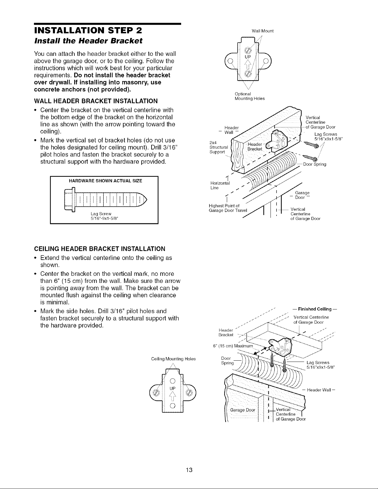
INSTALLATION STEP 2
Install the Header Bracket
You can attach the header bracket either to the wall
above the garage door, or to the ceiling. Follow the
instructions which will work best for your particular
requirements. Do not install the header bracket
over drywall. If installing into masonry, use
concrete anchors (not provided).
WALL HEADER BRACKET INSTALLATION
• Center the bracket on the vertical centerline with
the bottom edge of the bracket on the horizontal
line as shown (with the arrow pointing toward the
ceiling).
• Mark the vertical set of bracket holes (do not use
the holes designated for ceiling mount). Drill 3/16"
pilot holes and fasten the bracket securely to a
structural support with the hardware provided.
HARDWARE SHOWN ACTUAL SIZE
J EI I I EE 1,1
Lag Screw
5/16"-9xl -5/8"
Optional
Mounting Holes
Header
- Wall -
2x4
Structural
Support
I
1
Horizontal
Line / /
Highest Point of
Garage Door Travel
/
Wall Mount
\ /
Vertical
Centerline
Door Spring
Garage
- Door-
Vertical
Centerline
of Garage Door
÷ Door
Lag Screws
5/16"x9x1-5/8"
/
CEILING HEADER BRACKET INSTALLATION
• Extend the vertical centerline onto the ceiling as
shown.
• Center the bracket on the vertical mark, no more
than 6" (15 cm) from the wall. Make sure the arrow
is pointing away from the wall. The bracket can be
mounted flush against the ceiling when clearance
is minimal.
• Mark the side holes. Drill 3/16" pilot holes and
fasten bracket securely to a structural support with
the hardware provided.
Ceiling Mounting Holes
6" (15 cm) Maximum
Door
Spring
I Finished Ceiling I
Vertical Centerline
of Garage Door
Center]ine
of Garage Door
Lag Screws
5/16"x9x1-5/8"
-- Header Wall --
13
Page 14
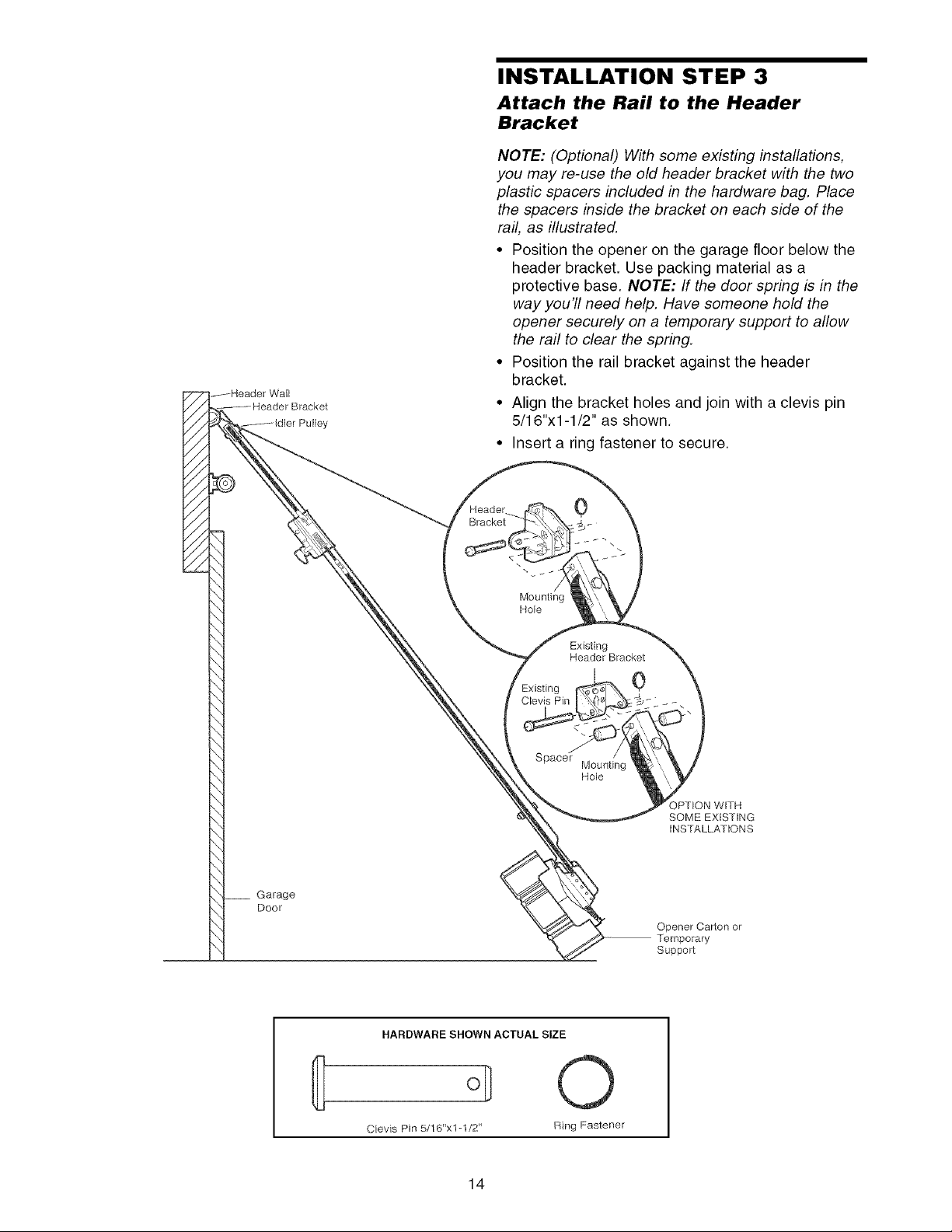
INSTALLATION STEP 3
Attach the Rail to the Header
Bracket
NOTE: (Optional) With some existing installations,
you may re-use the old header bracket with the two
plastic spacers included in the hardware bag. Place
the spacers inside the bracket on each side of the
rail, as illustrated.
• Position the opener on the garage floor below the
header bracket. Use packing material as a
protective base. NOTE: If the door spring is in the
way you'll need help. Have someone hold the
opener securely on a temporary support to allow
the rail to clear the spring.
• Position the rail bracket against the header
bracket.
//
//
//
//
//
• Align the bracket holes and join with a clevis pin
5/16"xl-1/2" as shown.
• Insert a ring fastener to secure.
Garage
Door
Bracket
\
\
Mounting
Hole
Clevis Pin
Spacer Mounting
0
\
Existing
Header Bracket
Hole
0
)PTION WITH
SOME EXISTING
iNSTALLATIONS
Opener Carton or
Temporary
Support
HARDWARE SHOWN ACTUAL SIZE
C{evis Pin 5/16"xl -1/2" Ring Fastener
14
Page 15
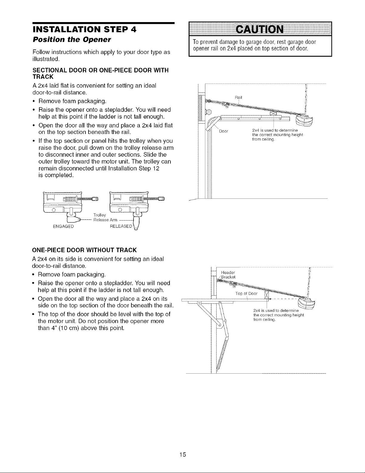
INSTALLATION STEP 4
Position the Opener
Follow instructions which apply to your door type as
illustrated.
SECTIONAL DOOR OR ONE-PIECE DOOR WITH
TRACK
A 2x4 laid flat is convenient for setting an ideal
door-to-rail distance.
• Remove foam packaging.
• Raise the opener onto a stepladder. You will need
help at this point if the ladder is not tall enough.
• Open the door all the way and place a 2x4 laid flat
on the top section beneath the rail.
• If the top section or panel hits the trolley when you
raise the door, pull down on the trolley release arm
to disconnect inner and outer sections. Slide the
outer trolley toward the motor unit. The trolley can
remain disconnected until Installation Step 12
is completed.
To prevent damageto garage door, rest garagedoor
opener rail on 2x4 placed on top section of door.
ENGAGED
ONE-PIECE DOOR WITHOUT TRACK
A 2x4 on its side is convenient for setting an ideal
door-to-rail distance.
• Remove foam packaging.
• Raise the opener onto a stepladder. You will need
help at this point if the ladder is not tall enough.
• Open the door all the way and place a 2x4 on its
side on the top section of the door beneath the rail.
• The top of the door should be level with the top of
the motor unit. Do not position the opener more
than 4" (10 cm) above this point.
i tfhemCOrr_ Ctgr_o u n t i ng height
15
Page 16
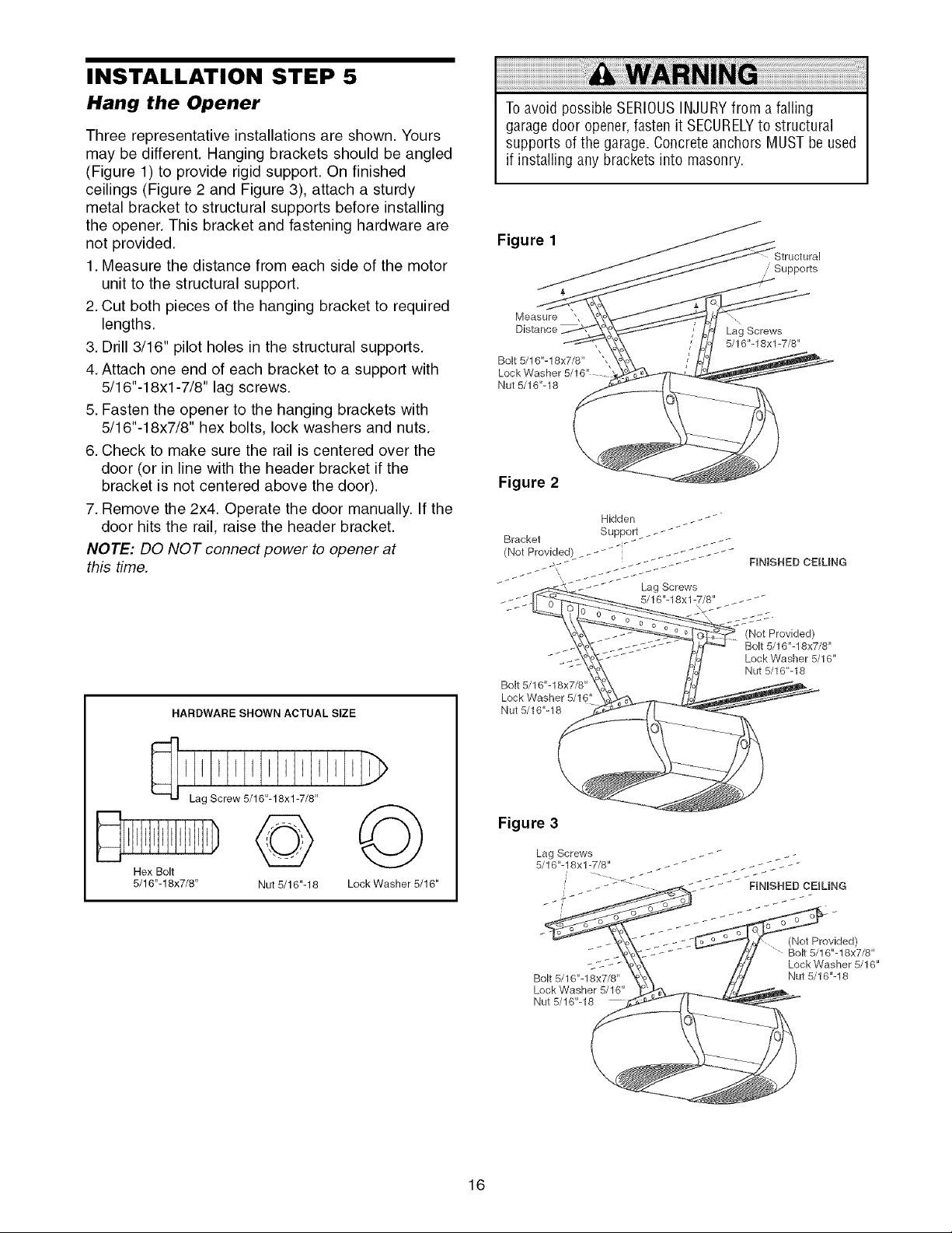
INSTALLATION STEP 5
Hang the Opener
Three representative installations are shown. Yours
may be different. Hanging brackets should be angled
(Figure 1) to provide rigid support. On finished
ceilings (Figure 2 and Figure 3), attach a sturdy
metal bracket to structural supports before installing
the opener. This bracket and fastening hardware are
not provided.
1. Measure the distance from each side of the motor
unit to the structural support.
2. Cut both pieces of the hanging bracket to required
lengths.
3. Drill 3/16" pilot holes in the structural supports.
4. Attach one end of each bracket to a support with
5/16"-18xl -7/8" lag screws.
5. Fasten the opener to the hanging brackets with
5/16"-18x7/8" hex bolts, lock washers and nuts.
6. Check to make sure the rail is centered over the
door (or in line with the header bracket if the
bracket is not centered above the door).
7. Remove the 2x4. Operate the door manually. If the
door hits the rail, raise the header bracket.
NOTE: DO NOT connect power to opener at
this time.
Toavoid possible SERIOUSINJURYfrom a falling
garage door opener,fasten it SECURELYto structural
supports of the garage.Concrete anchors MUSTbe used
if installing any brackets into masonry.
Figure 1
,,' Supports
Measure ',
Distance
Bolt 5/16"-18x7/8"
Lock Washer 5/16"
Nut 5/16"-18
'X
Lag Screws
5/16"-18xl -7/8"
Figure 2
FINISHED CEILING
Lag Screws
5/16"-18xl-7/8" -_-_
HARDWARE SHOWN ACTUAL SIZE
Hex Bolt
5/16"-18x7/8" Nut 5/16"-18 Lock Washer 5/16"
Bolt 5/16"-18x7/8
Lock Washer 5/16"
Nut 5/16"-18
Figure 3
Lag Screws
5/16"-18xl -7/8"
i'
Bolt 5/16"-18x7/8"
Lock Washer 5/16"
Nut 5/16"-18
(Not Provided)
Bolt 5/16"-18x7/8"
Lock Washer 5/16"
Nut 5/16"-18
(Not Provided)
Bolt 5/16"-18x7/8"
Lock Washer 5/16"
Nut 5/16"-18
16
Page 17
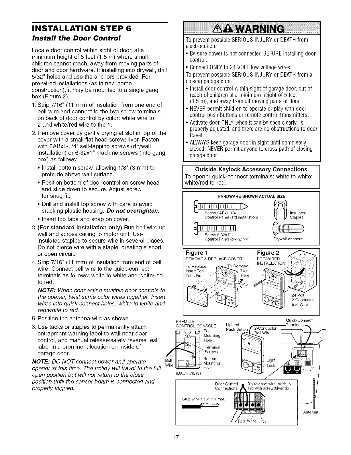
INSTALLATION STEP 6
Install the Door Control
Locate door control within sight of door, at a
minimum height of 5 feet (1.5 m) where small
children cannot reach, away from moving parts of
door and door hardware. If installing into drywall, drill
5/32" holes and use the anchors provided. For
pre-wired installations (as in new home
construction), it may be mounted to a single gang
box (Figure 2).
1.Strip 7/16" (11 mm) of insulation from one end of
bell wire and connect to the two screw terminals
on back of door control by color: white wire to
2 and white/red wire to the 1.
2. Remove cover by gently prying at slot in top of the
cover with a small flat head screwdriver. Fasten
with 6ABx1-1/4" self-tapping screws (drywall
installation) or 6-32xl" machine screws (into gang
box) as follows:
• Install bottom screw, allowing 1/8" (3 mm) to
protrude above wall surface.
• Position bottom of door control on screw head
and slide down to secure. Adjust screw
for snug fit.
• Drill and install top screw with care to avoid
cracking plastic housing. Do not overtighten.
• Insert top tabs and snap on cover.
3. (For standard installation only) Run bell wire up
wall and across ceiling to motor unit. Use
insulated staples to secure wire in several places.
Do not pierce wire with a staple, creating a short
or open circuit.
4. Strip 7/16" (11 mm) of insulation from end of bell
wire. Connect bell wire to the quick-connect
terminals as follows: white to white and white/red
to red.
NOTE: When connecting multiple door controls to
the opener, twist same color wires together. Insert
wires into quick-connect holes: white to white and
red/white to red.
5. Position the antenna wire as shown.
6. Use tacks or staples to permanently attach
entrapment warning label to wall near door
control, and manual release/safety reverse test
label in a prominent location on inside of
garage door.
NOTE: DO NOT connect power and operate
opener at this time. The trolley will travel to the full
open position but will not return to the close
position until the sensor beam is connected and
properly aligned.
Toprevent possible SERIOUSINJURYor DEATHfrom
electrocution:
• Besure power is not connected BEFOREinstalling door
control.
• ConnectONLYto 24VOLTlow voltagewires.
Toprevent possible SERIOUSINJURYor DEATHfrom a
closing garage door:
• Install door control within sight of garage door,out of
reachof children at a minimum height of 5 feet
(1.5 m), and awayfrom all moving parts of door.
• NEVERpermit children to operate or playwith door
control push buttons or remote control transmitters.
• Activate door ONLYwhen it can beseenclearly, is
properly adjusted,and there are no obstructions to door
travel.
• ALWAYSkeepgarage door in sight until completely
closed. NEVERpermit anyone to cross path of closing
garage door.
Outside Keylock Accessory Connections
To opener quick-connect terminals: white to white;
white/red to red.
Control Panel (std installation)
Control Panel (pre-wired)
Figure 1
REMOVE & REPLACE COVER
To Replace,
Insert Top Twist
Tabs First _ / _' Here
PREMIUM
CONTROL CONSOLE
Top
Mounting
Hole
Terminal
Screws
Bottom
..... _ Hole
(BACK VIEW)
Mounting
HARDWARE SHOWN ACTUAL SIZE
Drywall Anchors
Figure 2
PRE-WIRED
INSTALLATION
Lighted
Push Button
\
Door Control To release wire, push in
Connections tab with screwdriver tip
Bell Wire
Insulated
Staples
24 Volt
2-Conductor
Bell Wire
Quick-Connect
17
Antenna
Red White Grey
Page 18
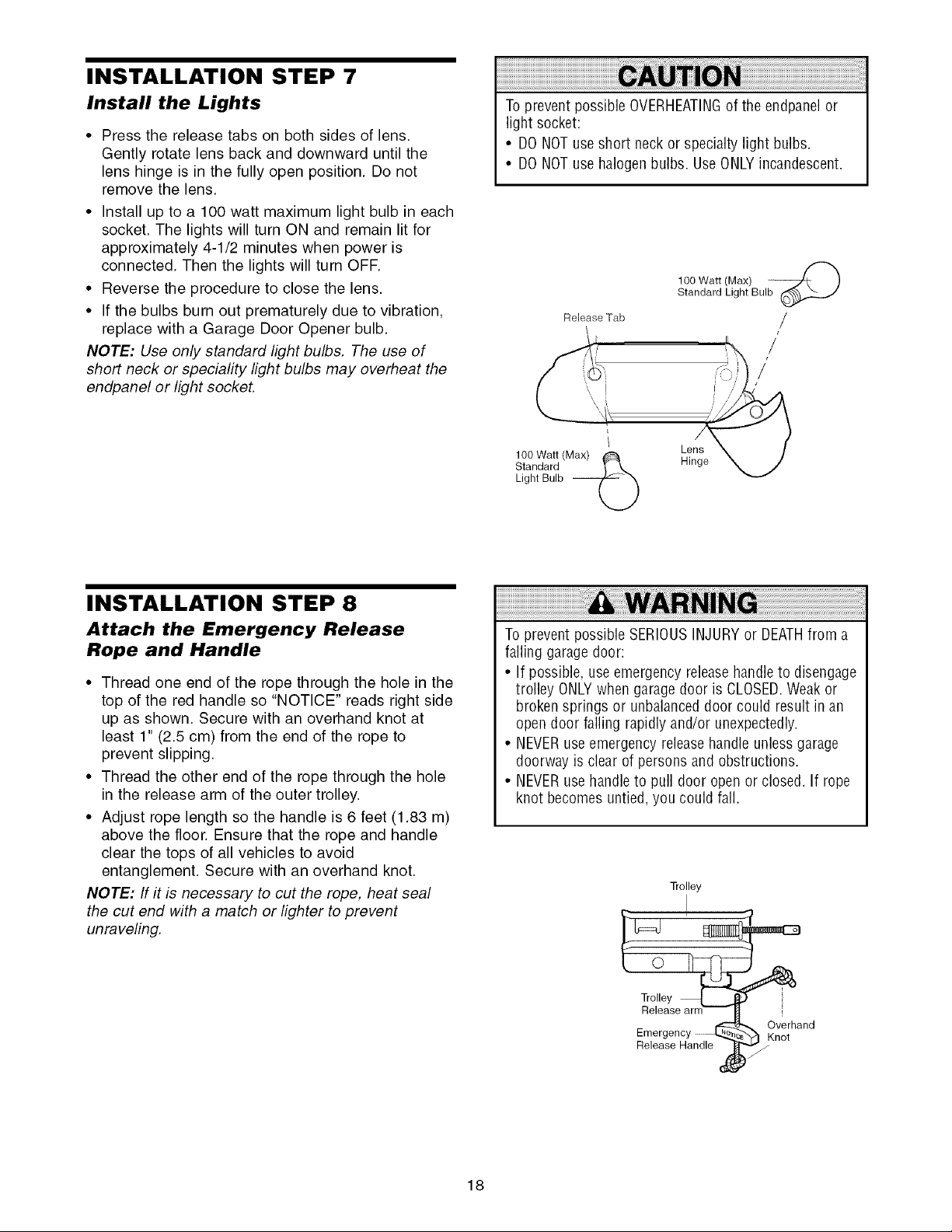
INSTALLATION STEP 7
Install the Lights
• Press the release tabs on both sides of lens.
Gently rotate lens back and downward until the
lens hinge is in the fully open position. Do not
remove the lens.
• Install up to a 100 watt maximum light bulb in each
socket. The lights will turn ON and remain lit for
approximately 4-1/2 minutes when power is
connected. Then the lights will turn OFF.
• Reverse the procedure to close the lens.
• If the bulbs burn out prematurely due to vibration,
replace with a Garage Door Opener bulb.
NOTE: Use only standard light bulbs. The use of
short neck or speciafity light bulbs may overheat the
endpanel or light socket.
Toprevent possible OVERHEATINGof the endpanelor
light socket:
• DONOTuseshort neckor specialty light bulbs.
• DONOTuse halogenbulbs. UseONLYincandescent.
100 Watt (Max)
Standard Light Bulb
Release Tab
/
/
/
100 Watt (Max) _ Lens
Standard Hinge
Light Bulb --
©
INSTALLATION STEP 8
Attach the Emergency Release
Rope and Handle
• Thread one end of the rope through the hole in the
top of the red handle so "NOTICE" reads right side
up as shown. Secure with an overhand knot at
least 1" (2.5 cm) from the end of the rope to
prevent slipping.
• Thread the other end of the rope through the hole
in the release arm of the outer trolley.
• Adjust rope length so the handle is 6 feet (1.83 m)
above the floor. Ensure that the rope and handle
clear the tops of all vehicles to avoid
entanglement. Secure with an overhand knot.
NOTE: If it is necessary to cut the rope, heat seal
the cut end with a match or lighter to prevent
unraveling.
To prevent possible SERIOUSINJURYor DEATHfrom a
falling garage door:
• If possible, useemergency releasehandleto disengage
trolley ONLYwhen garage door is CLOSED.Weakor
brokensprings or unbalanced door could result in an
open door falling rapidly and/or unexpectedly.
• NEVERuseemergencyreleasehandle unless garage
doorway is clear of persons and obstructions.
• NEVERusehandleto pull door open orclosed. If rope
knot becomes untied, you could fall.
Trolley
Q
Emergency _ Overhand
Release Handle f
} Knot
18
Page 19
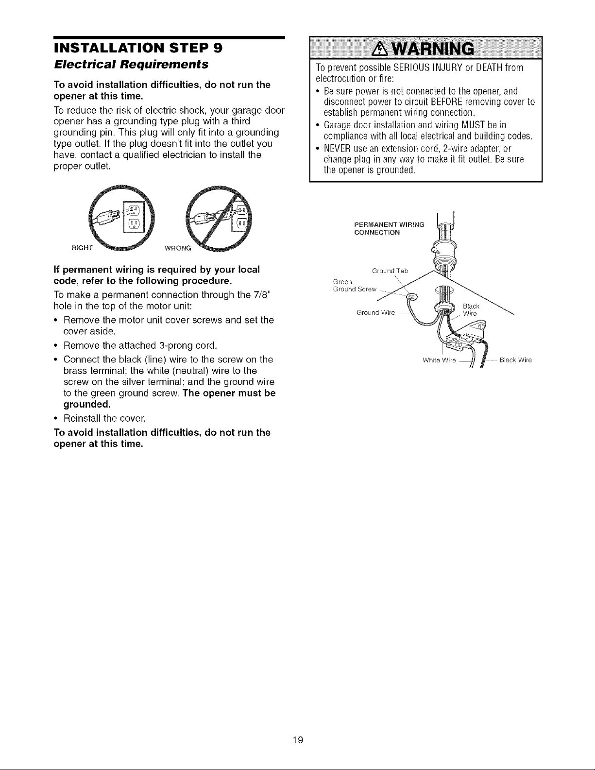
INSTALLATION STEP 9
Electrical Requirements
To avoid installation difficulties, do not run the
opener at this time.
To reduce the risk of electric shock, your garage door
opener has a grounding type plug with a third
grounding pin. This plug will only fit into a grounding
type outlet. If the plug doesn't fit into the outlet you
have, contact a qualified electrician to install the
proper outlet.
WRONG
If permanent wiring is required by your local
code, refer to the following procedure.
To make a permanent connection through the 7/8"
hole in the top of the motor unit:
• Remove the motor unit cover screws and set the
cover aside.
• Remove the attached 3-prong cord.
• Connect the black (line) wire to the screw on the
brass terminal; the white (neutral) wire to the
screw on the silver terminal; and the ground wire
to the green ground screw. The opener must be
grounded.
• Reinstall the cover.
To avoid installation difficulties, do not run the
opener at this time.
To prevent possible SERIOUSINJURYor DEATHfrom
electrocution or fire:
• Besure power is not connected to the opener,and
disconnect power to circuit BEFOREremoving cover to
establish permanentwiring connection.
• Garagedoor installation and wiring MUSTbe in
compliance with all localelectrical and building codes.
• NEVERusean extension cord, 2-wire adapter,or
changeplug in any way to makeit fit outlet. Besure
the opener is grounded.
PERMANENT WiRiNG
CONNECTION
Ground Tab
Green
Ground Screw
Ground Wire Wire
N\
Black
White Wire BJack Wire
19
Page 20
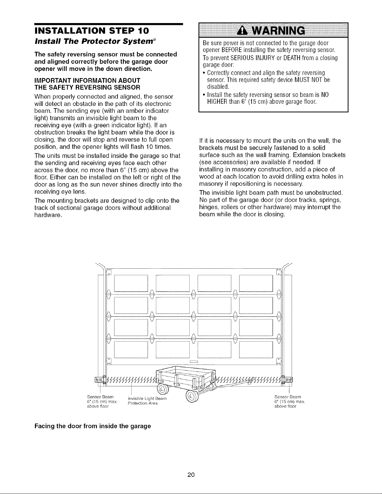
INSTALLATION STEP 10
Install The Protector System ®
The safety reversing sensor must be connected
and aligned correctly before the garage door
opener will move in the down direction.
IMPORTANT INFORMATION ABOUT
THE SAFETY REVERSING SENSOR
When properly connected and aligned, the sensor
will detect an obstacle in the path of its electronic
beam. The sending eye (with an amber indicator
light) transmits an invisible light beam to the
receiving eye (with a green indicator light). If an
obstruction breaks the light beam while the door is
closing, the door will stop and reverse to full open
position, and the opener lights will flash 10 times.
The units must be installed inside the garage so that
the sending and receiving eyes face each other
across the door, no more than 6" (15 cm) above the
floor. Either can be installed on the left or right of the
door as long as the sun never shines directly into the
receiving eye lens.
The mounting brackets are designed to clip onto the
track of sectional garage doors without additional
hardware.
Be sure power is not connectedto the garage door
opener BEFOREinstalling the safety reversingsensor.
To prevent SERIOUSINJURYor DEATHfrom a closing
garage door:
• Correctly connect andalign the safety reversing
sensor.This required safety device MUSTNOTbe
disabled.
• Install the safety reversingsensor so beam is NO
HIGHERthan 6" (15 cm) above garage floor.
If it is necessary to mount the units on the wall, the
brackets must be securely fastened to a solid
surface such as the wall framing. Extension brackets
(see accessories) are available if needed. If
installing in masonry construction, add a piece of
wood at each location to avoid drilling extra holes in
masonry if repositioning is necessary.
The invisible light beam path must be unobstructed.
No part of the garage door (or door tracks, springs,
hinges, rollers or other hardware) may interrupt the
beam while the door is closing.
Sensor Beam invisible Light Beam
6" (15 cm) max, Protection Area
above floor
Facing the door from inside the garage
2O
Sensor Beam
6" (15 cm) max,
above floor
Page 21
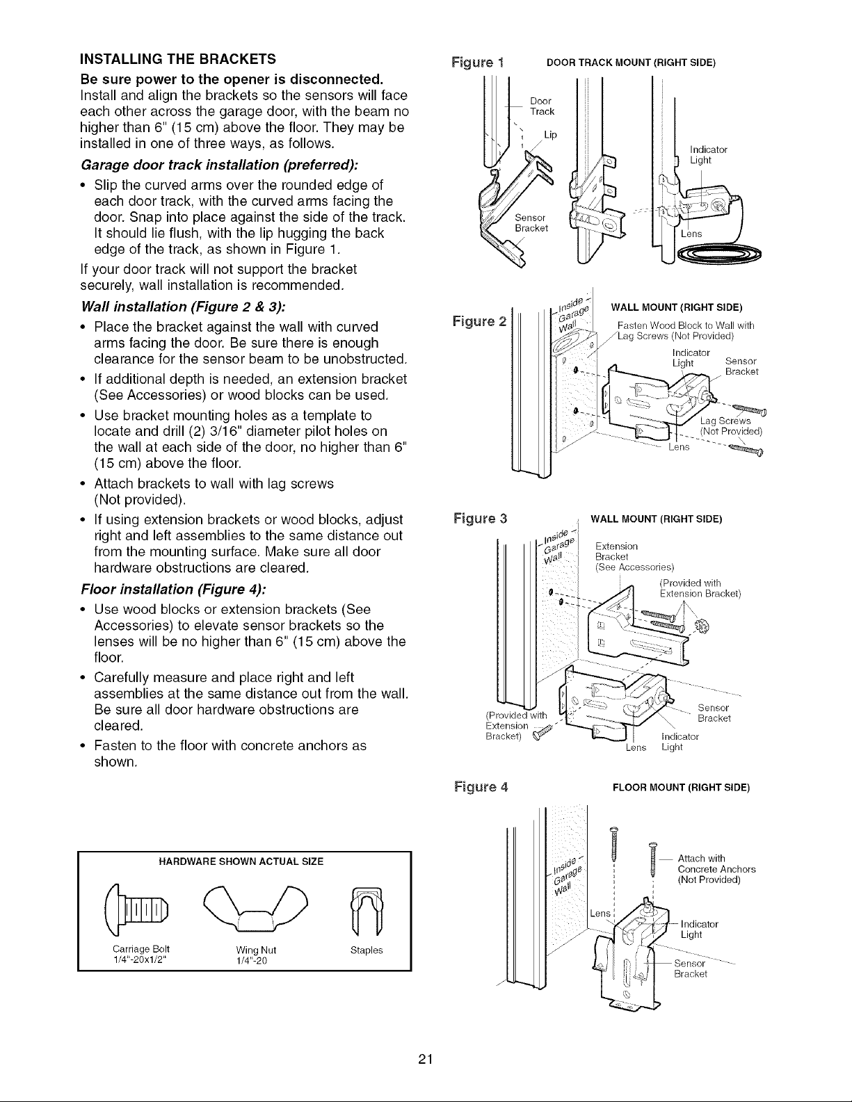
INSTALLING THE BRACKETS
Be sure power to the opener is disconnected.
Install and align the brackets so the sensors will face
each other across the garage door, with the beam no
higher than 6" (15 cm) above the floor. They may be
installed in one of three ways, as follows.
Garage door track installation (preferred):
• Slip the curved arms over the rounded edge of
each door track, with the curved arms facing the
door. Snap into place against the side of the track.
It should lie flush, with the lip hugging the back
edge of the track, as shown in Figure 1.
If your door track will not support the bracket
securely, wall installation is recommended.
Wall installation (Figure 2 & 3):
• Place the bracket against the wall with curved
arms facing the door. Be sure there is enough
clearance for the sensor beam to be unobstructed.
• If additional depth is needed, an extension bracket
(See Accessories) or wood blocks can be used.
• Use bracket mounting holes as a template to
locate and drill (2) 3/16" diameter pilot holes on
the wall at each side of the door, no higher than 6"
(15 cm) above the floor.
• Attach brackets to wall with lag screws
(Not provided).
• If using extension brackets or wood blocks, adjust
right and left assemblies to the same distance out
from the mounting surface. Make sure all door
hardware obstructions are cleared.
Floor installation (Figure 4):
• Use wood blocks or extension brackets (See
Accessories) to elevate sensor brackets so the
lenses will be no higher than 6" (15 cm) above the
floor.
• Carefully measure and place right and left
assemblies at the same distance out from the wall.
Be sure all door hardware obstructions are
cleared.
• Fasten to the floor with concrete anchors as
shown.
Figure DOOR TRACK MOUNT (RIGHT SIDE)
Door
Track
\
Indicator
Light
Sensor
Bracket
%
WALL MOUNT (RIGHT SIDE)
Figure 2
_.:_ _ L,_, Bracket
Figure 3 WALL MOUNT (RIGHT SIDE)
(Provided with
Extension
Bracket) _ ¢_"
Fasten Wood Block to Wall with
_Lag Screws (Not Provided)
Indicator
Light Sensor
Lens "--_
Extension
Bracket
(See Accessories)
(Provided with
Extension Bracket)
indicator
Lens
Light
Sensor
Bracket
HARDWARE SHOWN ACTUAL SIZE
Carriage Bolt Wing Nut
1/4"-20xl/2" 1/4"-20
Staples
Figure 4 FLOOR MOUNT (RIGHT SIDE)
I Attach with
i (Not Provided)
21
Concrete Anchors
Light
Bracket
Page 22
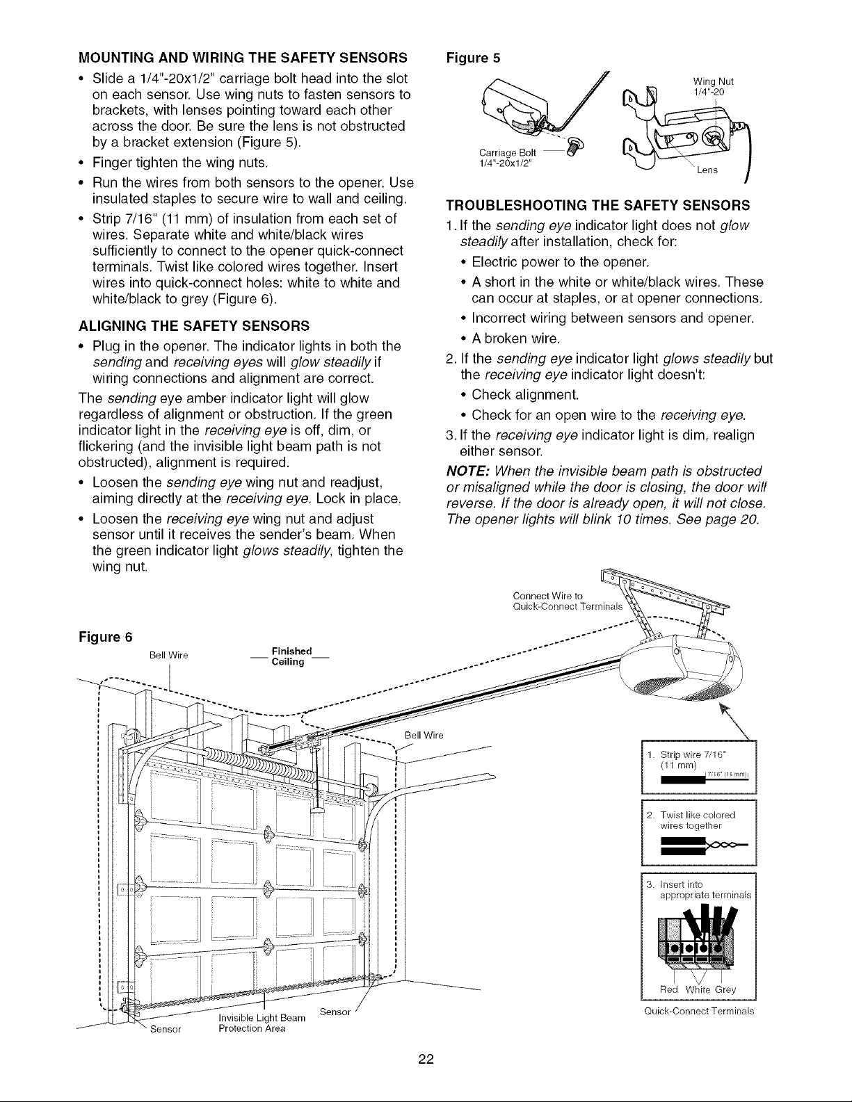
MOUNTING AND WIRING THE SAFETY SENSORS
• Slide a 1/4"-20xl/2" carriage bolt head into the slot
on each sensor. Use wing nuts to fasten sensors to
brackets with lenses pointing toward each other
across the door. Be sure the lens is not obstructed
by a bracket extension (Figure 5).
• Finger tighten the wing nuts.
• Run the wires from both sensors to the opener. Use
insulated staples to secure wire to wall and ceiling.
• Strip 7/16" (11 mm) of insulation from each set of
wires. Separate white and white/black wires
sufficiently to connect to the opener quick-connect
terminals. Twist like colored wires together. Insert
wires into quick-connect holes: white to white and
white/black to grey (Figure 6).
ALIGNING THE SAFETY SENSORS
• Plug in the opener. The indicator lights in both the
sending and receiving eyes will glow steadily if
wiring connections and alignment are correct.
The sending eye amber indicator light will glow
regardless of alignment or obstruction. If the green
indicator light in the receiving eye is off, dim, or
flickering (and the invisible light beam path is not
obstructed), alignment is required.
• Loosen the sending eye wing nut and readjust,
aiming directly at the receiving eye. Lock in place.
• Loosen the receiving eye wing nut and adjust
sensor until it receives the sender's beam. When
the green indicator light glows steadily, tighten the
wing nut.
Figure 5
Wing Nut
%
Carriage Bolt _)
1/4"-20xl/2"
TROUBLESHOOTING THE SAFETY SENSORS
1. If the sending eye indicator light does not glow
steadily after installation, check for:
• Electric power to the opener.
• A short in the white or white/black wires. These
can occur at staples, or at opener connections.
• Incorrect wiring between sensors and opener.
• A broken wire.
2. If the sending eye indicator light glows steadily but
the receiving eye indicator light doesn't:
• Check alignment.
• Check for an open wire to the receiving eye.
3. If the receiving eye indicator light is dim, realign
either sensor.
NOTE: When the invisible beam path is obstructed
or misaligned while the door is closing, the door will
reverse. If the door is already open, it will not close.
The opener lights will blink 10 times. See page 20.
Figure 6
Bell Wire
Sensor
Invisible Light Beam
Protection Area
Sensor
Bell Wire
1. Strip wire 7/16"
(11 ram)
2. Twist like colored
wires together
3. Insert into
appropriate terminals
Red White Grey
Quick-Connect Terminals
17/16" {11 mm)l
22
Page 23
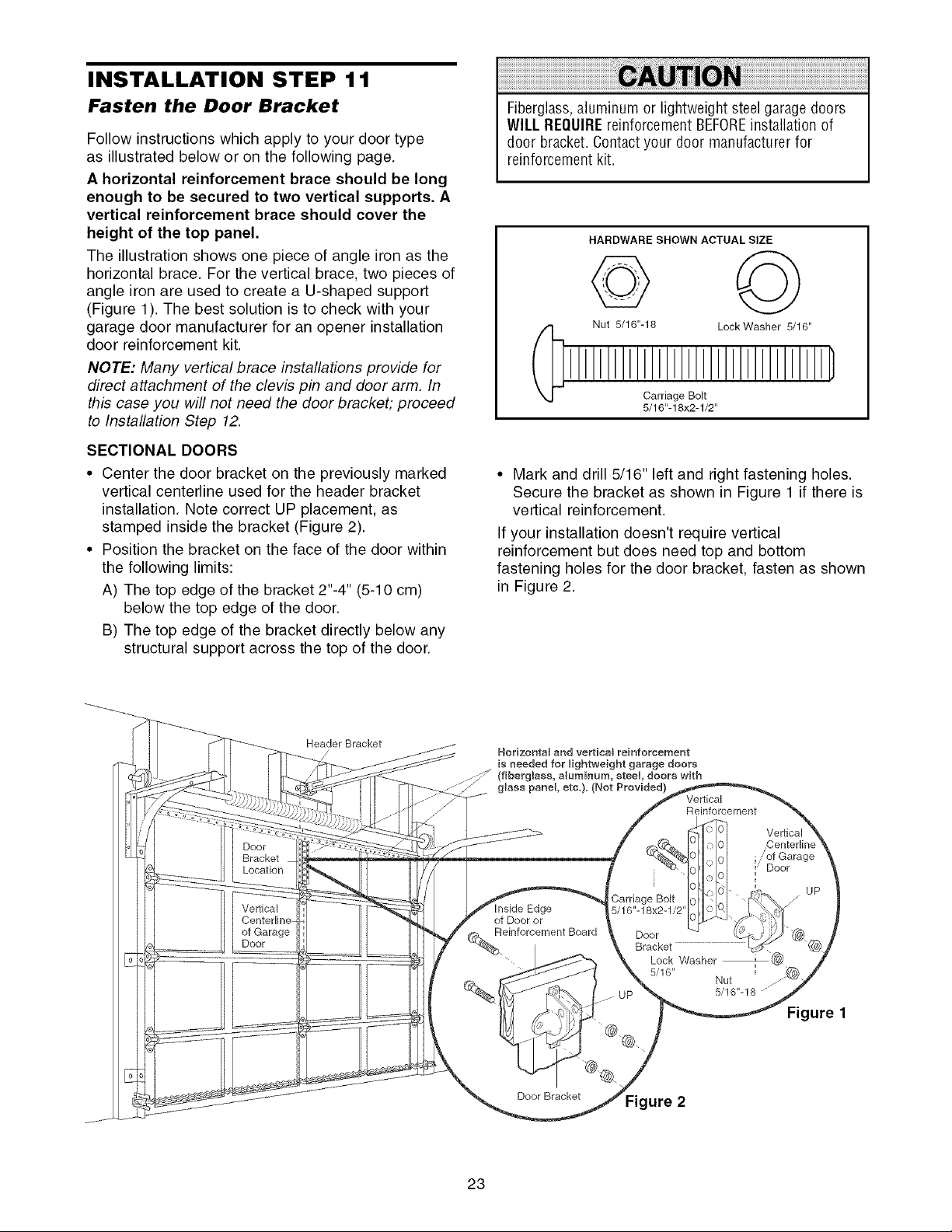
INSTALLATION STEP 11
Fasten the Door Bracket
Follow instructions which apply to your door type
as illustrated below or on the following page.
A horizontal reinforcement brace should be long
enough to be secured to two vertical supports. A
vertical reinforcement brace should cover the
height of the top panel.
The illustration shows one piece of angle iron as the
horizontal brace. For the vertical brace, two pieces of
angle iron are used to create a U-shaped support
(Figure 1). The best solution is to check with your
garage door manufacturer for an opener installation
door reinforcement kit.
NOTE: Many vertical brace installations provide for
direct attachment of the clevis pin and door arm. In
this case you will not need the door bracket; proceed
to Installation Step 12.
SECTIONAL DOORS
• Center the door bracket on the previously marked
vertical centerline used for the header bracket
installation. Note correct UP placement, as
stamped inside the bracket (Figure 2).
• Position the bracket on the face of the door within
the following limits:
A) The top edge of the bracket 2"-4" (5-10 cm)
below the top edge of the door.
B) The top edge of the bracket directly below any
structural support across the top of the door.
Fiberglass,aluminum or lightweight steel garage doors
WILL REQUIREreinforcement BEFOREinstallation of
door bracket. Contactyour door manufacturer for
reinforcement kit.
HARDWARE SHOWN ACTUAL SIZE
© ©
Nut 5/16"-18 Lock Washer 5/16"
Carriage Bolt
5/16"-18x2-1/2"
• Mark and drill 5/16" left and right fastening holes.
Secure the bracket as shown in Figure 1 if there is
vertical reinforcement.
If your installation doesn't require vertical
reinforcement but does need top and bottom
fastening holes for the door bracket, fasten as shown
in Figure 2.
Door
Bracket
Location
Vertical
of Garage
Door
Header Bracket
/
Horizontal and vertical reinforcement
is needed for lightweight garage doors
lass, aluminum, steel, doors with
glass panel, etc.}. (Not Provided)
Edge
of Door or
%Reinforcement Board
Door Bracket Figure 2
.Carriage Bolt
5/16"-18x2-1/2
23
Door
Bracket
Lock Washer
5/16"
Vertical
Reinforcement
Nut
5/16"-18 '''j
Vertical
.'of Garage
Door
Figure
UP
Page 24

ONE-PIECEDOORS
Please read and comply with the warnings and
reinforcement instructions on the previous page.
They apply to one-piece doors also.
• Center the door bracket on the top of the door, in
line with the header bracket as shown. Mark either
the left and right, or the top and bottom holes.
• Drill 5/16" pilot holes and fasten the bracket with
hardware supplied.
If the door has no exposed framing, drill 3/16" pilot
holes and fasten the bracket with 5/16"x1-1/2" lag
screws (not provided) to the top of the door.
NOTE: The door bracket may be installed on the top
edge of the door if required for your installation.
(Refer to the dotted line optional placement drawing.)
Drill 3/16" pilot holes and substitute 5/16"xl- 1/2" lag
screws (not provided) to fasten the bracket to the
door.
HARDWARE SHOWN ACTUAL SIZE
© ©
Nut 5/16"-16 Lock Washer 5/16"
Carriage Bolt
5/16"-18x2-1/2"
Header Wall
Header
Bracket
Optional
Placement
of Door
Bracket
2x4
Door
Bracket
Vertical
Centerline
of Garage
Door
HodzontaU and verticaU
reinforcement is needed for
(fiberglass, aUuminum, steel,
door with gUass panel etc.).
(Net Provided)
garage doors
JJJ_
5/16"-18
Door
Bracket
®
' 5/16"
i
i
i
Carriage Bolt
Lock
Washer
Top of Door
Top Edge
Optional
Placement
For a door with no exposed framing,
or for the optional installation, use
5/16"x1-1/2" lag screws (Not Provided)
to fasten door bracket.
24
5/16"-18x2-1/2"
Page 25

INSTALLATION STEP 12
Connect Door Arm to Trolley
Follow instructions which apply to your door type as
illustrated below and on the following page.
SECTIONAL DOORS ONLY
• Make sure garage door is fully closed. Pull the
emergency release handle to disconnect the outer
trolley from the inner trolley. Slide the outer trolley
back (away from the pulley) about 8" (20 cm) as
shown in Figures 1,2 and 3.
• Figure 1:
- Fasten straight door arm section to outer trolley
with the 5/16"x1" clevis pin. Secure the
connection with a ring fastener.
- Fasten curved section to the door bracket in the
same way, using the 5/16"x1-1/4" clevis pin.
• Figure 2:
- Bring arm sections together. Find two pairs of
holes that line up and join sections. Select holes
as far apart as possible to increase door arm
rigidity.
• Figure 3, Hole alignment alternative:
- If holes in curved arm are above holes in straight
arm, disconnect straight arm. Cut about 6"
(15 cm) from the solid end. Reconnect to trolley
with cut end down as shown.
- Bring arm sections together.
- Find two pairs of holes that line up and join with
bolts, lock washers and nuts.
• Pull the emergency release handle toward the
opener at a 45° angle so that the trolley release
arm is horizontal. Proceed to Adjustment Step 1,
page 27. Trolley will re-engage automatically when
opener is operated.
Figure 1
Door Bracket
Figure 2
©
Nut 5/16"-18
Clevis Pin
5/16"xl" (Trolley)
HARDWARE SHOWN ACTUAL SIZE
Lock Washer 5/16" Ring Fastener
o-1{ el
Clevis Pin Hex Bolt
5/16"x1-1/4" (Door Bracket) 5/16"-18x7/8"
25
Figure 3
Pulley
",, i i
"ie-_" (2ocm)_i_,.-..-)i
Trolley / / L
Lock /o/
Nuts 5/16" /o7
Washers/o-/
//
ot_ _ Cut this end
// I
Page 26

ALL ONE-PIECE DOORS
1.Assemble the door arm, Figure 4:
• Fasten the straight and curved door arm sections
together to the longest possible length (with a 2
or 3 hole overlap).
• With the door closed, connect the straight door
arm section to the door bracket with the
5/16"x1-1/4" clevis pin.
• Secure with a ring fastener.
2. Adjustment procedures, Figure 5:
• On one-piece doors, before connecting the door
arm to the trolley, the travel limits must be
adjusted. Limit adjustment screws are located on
the left side panel as shown on page 27. Follow
adjustment procedures below.
• Open door adjustment: decrease UP
travel limit
- Turn the UP limit adjustment screw
counter-clockwise 4 turns.
- Press the Door Control push button. The trolley
will travel to the fully open position.
- Manually raise the door to the open position
(parallel to the floor), and lift the door arm to the
trolley The arm should touch the trolley just in
back of the door arm connector hole. Refer to
the fully open trolley/door arm positions in the
illustration. If the arm does not extend far
enough, adjust the limit further. One full turn
equals 2" (5 cm) of trolley travel.
• Closed door adjustment: decrease DOWN
travel limit
- Turn the DOWN limit adjustment screw
clockwise 4 complete turns.
Figure 5
inner Trolley
Door
Bracket
Clevis Pin Straight
5/16"x1-1/4" Arm
Figure 4
Bolts
5/16"-18x7/8
Fastener
Lock
Washers
5/16"
Nuts
5/16"-18
Curved
Door Arm
- Press the Door Control push button. The trolley
will travel to the fully closed position.
- Manually close the door and lift the door arm to
the trolley. The arm should touch the trolley just
ahead of the door arm connector hole. Refer to
the fully closed trolley/door arm positions in the
illustration. If the arm is behind the connector
hole, adjust the limit further. One full turn equals
2" (5 cm) of trolley travel.
3. Connect the door arm to the trolley:
• Close the door and join the curved arm to the
connector hole in the trolley with the remaining
clevis pin It may be necessary to lift the door
slightly to make the connection.
• Secure with a ring fastener.
• Run the opener through a complete travel cycle.
If the door has a slight "backward" slant in full
open position as shown in the illustration,
decrease the UP limit until the door is parallel
to the floor.
NOTE: When setting the up limit on the following
page, the door should not have a "backward" slant
when fully open as illustrated below. A slight
backward slant will cause unnecessary bucking
and/or jerking operation as the door is being opened
or closed from the fully open position.
Release Handle
cy
Inner Trolley
Correct Angle _r _
Open Door (Incorrect)
26
Outer Trolley
Page 27

ADJUSTMENT STEP 1
Adjust the UP and DOWN Travel
Limits
Limit adjustment settings regulate the points at which
the door will stop when moving up or down.
To operate the opener, press the Door Control push
bar. Run the opener through a complete travel cycle.
• Does the door open and close completely?
• Does the door stay closed and not reverse
unintentionally when fully closed?
If your door passes both of these tests, no limit
adjustments are necessary unless the reversing test
fails (Adjustment Step 3, page 29).
Adjustment procedures are outlined below. Read the
procedures carefully before proceeding to
Adjustment Step 2. Use a screwdriver to make limit
adjustments. Run the opener through a complete
travel cycle after each adjustment.
NOTE: Repeated operation of the opener during
adjustment procedures may cause the motor to
overheat and shut off. Simply wait 15 minutes and
try again.
NOTE: If anything interferes with the door's upward
travel, it will stop. If anything interferes with the
door's downward travel (including binding or
unbalanced doors), it will reverse.
Without a properly installed safety reversalsystem,
persons (particularly small children) could be
SERIOUSLYINJUREDor KILLEDby a closing garage
door.
• Incorrect adjustment of garage doortravel limits will
interfere with proper operation of safety reversal
system.
• If onecontrol (force or travel limits) is adjusted, the
other control may also need adjustment.
• After ANYadjustments are made,the safety reversal
system MUSTbe tested. Door MUST reverse on
contact with 1-1/2" high (3.8 cm) object (or 2x4 laid
flat) on floor.
Toprevent damageto vehicles, be surefully open door
provides adequateclearance.
Cover Protection Bolt
LY
HOW AND WHEN TO ADJUST THE LIMITS
• If the door does not open completely but opens
at least five feet (1.5 m):
Increase up travel. Turn the UP limit adjustment
screw clockwise. One turn equals 2" (5 cm) of
travel.
NOTE: Toprevent the trolley from hitting the cover
protection bolt, keep a minimum distance of 2-4"
(5 cm - 10 cm) between the trolley and the bolt.
• If door does not open at least 5 feet (1.5 m):
Adjust the UP (open) force as explained in
Adjustment Step 2.
• If the door does not close completely:
Increase down travel. Turn the down limit
adjustment screw counterclockwise. One turn
equals 2" (5 cm) of travel.
If door still won't close completely and the trolley
bumps into the pulley bracket (page 4), try
lengthening the door arm (page 25) and
decreasing the down limit.
• If the opener reverses in fully closed position:
Decrease down travel. Turn the down limit
adjustment screw clockwise. One turn equals 2"
(5 cm) of travel.
Left Panel Limit Adjustment
ADJUSTMENT LABEL
If the door reverses when closing and there is
no visible interference to travel cycle:
If the opener lights are flashing, the Safety
Reversing Sensors are either not installed,
misaligned, or obstructed. See Troubleshooting,
page 22.
Test the door for binding: Pull the emergency
release handle. Manually open and close the door.
If the door is binding or unbalanced, call for a
trained door systems technician. If the door is
balanced and not binding, adjust the DOWN
(close) force. See Adjustment Step 2.
Screws
27
Page 28

ADJUSTMENT STEP 2
Adjust the Force
Force adjustment controls are located on the right
panel of the motor unit. Force adjustment settings
regulate the amount of power required to open and
close the door.
If the forces are set too light, door travel may be
interrupted by nuisance reversals in the down
direction and stops in the up direction. Weather
conditions can affect the door movement, so
occasional adjustment may be needed.
The maximum force adjustment range is about
3/4 of a complete turn. Do not force controls
beyond that point. Turn force adjustment controls
with a screwdriver.
NOTE: If anything interferes with the door's upward
travel, it will stop. If anything interferes with the
door's downward travel (including binding or
unbalanced doors), it will reverse.
Without a properly installed safety reversalsystem,
persons (particularly small children) could be
SERIOUSLYINJUREDor KILLEDby a closing garage
door.
• Too much force on garagedoor will interfere with
proper operation of safety reversalsystem.
• NEVERincreaseforce beyond minimum amount
requiredto close garage door.
• NEVERuseforce adjustments to compensate for a
binding or sticking garagedoor.
• If onecontrol (forceor travel limits) is adjusted,the
othercontrol may also need adjustment.
• After ANYadjustments are made,the safety reversal
system MUSTbetested. Door MUST reverseon
contact with 1-1/2" high (3.8 cm) object (or 2x4 laid
flat) on floor.
HOW AND WHEN TO ADJUST THE FORCES
1.Test the DOWN (close) force
• Grasp the door bottom when the door is about
halfway through DOWN (close) travel. The door
should reverse. Reversal halfway through down
travel does not guarantee reversal on a 1-1/2"
(3.8 cm) obstruction. See Adjustment Step 3,
page 29. If the door is hard to hold or doesn't
reverse, DECREASE the DOWN (close) force by
turning the control counterclockwise. Make small
adjustments until the door reverses normally.
After each adjustment, run the opener through a
complete cycle.
• If the door reverses during the down (close)
cycle and the opener lights aren't flashing,
INCREASE DOWN (close) force by turning the
control clockwise. Make small adjustments until
the door completes a close cycle. After each
adjustment, run the opener through a complete
travel cycle. Do not increase the force beyond the
minimum amount required to close the door.
2. Test the UP (open) force
• Grasp the door bottom when the door is about
halfway through UP (open) travel. The door
should stop. If the door is hard to hold or
doesn't stop, DECREASE UP (open) force by
turning the control counterclockwise. Make small
adjustments until the door stops easily and opens
fully. After each adjustment, run the opener
through a complete travel cycle.
• If the door doesn't open at least 5 feet (1.5 m),
INCREASE UP (open) force by turning the
control clockwise. Make small adjustments until
door opens completely. Readjust the UP limit if
necessary. After each adjustment, run the opener
through a complete travel cycle.
ADJUSTMENT LABEL
Open Force
Force Adjustment
Controls
Close Force
Antenna
28
Page 29

ADJUSTMENT STEP 3
Test the Safety Reversal System
TEST
• With the door fully open, place a 1-1/2" (3.8 cm)
board (or a 2x4 laid flat) on the floor, centered
under the garage door
• Operate the door in the down direction The door
must reverse on striking the obstruction
ADJUST
• If the door stops on the obstruction, it is not
traveling far enough in the down direction.
Increase the DOWN limit by turning the DOWN
limit adjustment screw counterclockwise 1/4 turn.
NOTE: On a sectional door, make sure limit
adjustments do not force the door arm beyond a
straight up and down position. See the illustration
on page 25.
• Repeat the test.
• When the door reverses on the 1-1/2" (3.8 cm)
board, remove the obstruction and run the opener
through 3 or 4 complete travel cycles to test
adjustment.
• If the unit continues to fail the Safety Reverse Test,
call for a trained door systems technician.
IMPORTANT SAFETY CHECK:
Test the Safety Reverse System after:
• Each adjustment of door arm length, limits, or
force controls.
• Any repair to or adjustment of the garage door
(including springs and hardware).
• Any repair to or buckling of the garage floor.
• Any repair to or adjustment of the opener.
Without a properly installed safety reversalsystem,
persons (particularly small children) could be
SERIOUSLYINJUREDor KILLEDby a closing garage
door.
• Safety reversalsystem MUST betested every month.
• If onecontrol (forceor travel limits) is adjusted,the
other control mayalso needadjustment.
• After ANYadjustments are made,the safety reversal
system MUSTbetested. Door MUST reverseon
contact with 1-1/2" high (3.8 cm) object (or 2x4 laid
flat) on the floor.
J .....
i
1/2 (3 8 cm) board
(or a 2x4 laid flat)
ADJUSTMENT STEP 4
Test The Protector System ®
• Press the remote control push button to open the
door.
• Place the opener carton in the path of the door.
• Press the remote control push button to close the
door. The door will not move more than an inch
(2.5 cm), and the opener lights will flash.
The garage door opener will not close from a remote
if the indicator light in either sensor is off (alerting
you to the fact that the sensor is misaligned or
obstructed).
If the opener closes the door when the safety
reversing sensor is obstructed (and the sensors
are no more than 6" (15 cm) above the floor), call
for a trained door systems technician.
Without a properly installed safety reversing sensor,
persons (particularly small children) could be
SERIOUSLYINJUREDor KILLEDby a closing garage
door.
Safety Reversing Sensor
29
Page 30

OPERATION
IMPORTANT SAFETY INSTRUCTIONS
To reduce the risk of SEVERE INJURY or DEATH:
1. READAND FOLLOWALL WARNINGSAND
INSTRUCTIONS.
2. ALWAYSkeep remote controls out of reach of children.
NEVERpermit children to operate or playwith garage
door control push buttons or remotecontrols.
3. ONLYactivategaragedoor when it can be seenclearly, it
is properly adjusted, and there are no obstructions to
door travel.
4. ALWAYSkeepgarage door in sight until completely
closed. NOONESHOULDCROSSTHEPATHOFTHE
MOVINGDOOR.
5. NOONESHOULDGOUNDERA STOPPED,PARTIALLY
OPENEDDOOR.
6. If possible, use emergency releasehandle to disengage
trolley ONLYwhen garage door is CLOSED.Weakor
brokensprings or unbalanced door could result in an
open door failing rapidly and/or unexpectedly.
7. NEVERuse emergencyreleasehandle unlessgarage
doorway is clear of persons and obstructions.
8. NEVERuse handleto pull garagedoor open or closed. If
rope knot becomes untied,you could fall.
Using Your Garage Door Opener
Your Security+ ®opener and hand-held remote
control have been factory-set to a matching code
which changes with each use, randomly accessing
over 100 billion new codes. Your opener will operate
with up to eight Security+ ®remote controls and one
Security+ ®Keyless Entry System. If you purchase a
new remote, or if you wish to deactivate any remote,
follow the instructions in the Programming section.
Activate your opener with any of the following:
• The hand-held Remote Control: Hold the large
push button down until the door starts to move.
• The wall-mounted Door Controh Hold the push
button or bar down until the door starts to move.
• The Keyless Entry (See Accessories): If provided
with your garage door opener, it must be
programmed before use. See Programming.
When the opener is activated (with the safety
reversing sensor correctly installed and aligned)
1. If open, the door will close. If closed, it will open.
2. If closing, the door will reverse.
3. If opening, the door will stop.
4. If the door has been stopped in a partially open
position, it will close.
5. If obstructed while closing, the door will reverse. If
the obstruction interrupts the sensor beam, the
opener lights will blink for five seconds.
9. If one control (force or travel limits) is adjusted, the
other control may also needadjustment.
10. After ANYadjustments are made,the safety reversal
system MUSTbe tested.
11. Safety reversalsystem MUSTbe tested every month.
Garagedoor must reverseon contact with 1-1/2" high
(3.8 cm) object (or a 2x4 laid flat) on the floor.
12. ALWAYSKEEPGARAGEDOORPROPERLYBALANCED
(see page3). An improperly balanceddoor may not
reversewhen required and could result in SEVERE
INJURYor DEATH.
13. All repairs to cables,spring assemblies and other
hardware, all of which are under EXTREMEtension,
MUSTbe madeby a trained door systemstechnician.
14. ALWAYSdisconnectelectric power to garage door
opener BEFOREmaking any repairs or removing
covers.
1sSAVETHESEINSTRUCTIONS.
6. If obstructed while opening, the door will stop.
7. If fully open, the door will not close when the beam
is broken. The sensor has no effect in the opening
cycle.
If the sensor is not installed, or is misaligned, the
door won't close from a hand-held remote. However,
you can close the door with the Door Control, the
Outdoor Key Switch, or Keyless Entry, if you activate
them until down travel is complete. If you release
them too soon, the door will reverse.
The opener lights will turn on under the following
conditions: when the opener is initially plugged in;
when power is restored after interruption; when the
opener is activated.
They will turn off automatically after 4-1/2 minutes or
provide constant light when the Light feature on the
Premium Control Console is activated. Bulb size is
1O0 watts maximum.
Security.I _ light feature: Lights will also turn on
when someone walks through the open garage door.
With a Premium Control Console, this feature may be
turned off as follows: With the opener lights off, press
and hold the light button for 10 seconds, until the
light goes on, then off again. To restore this feature,
start with the opener lights on, then press and hold
the light button for 10 seconds until the light goes off,
then on again.
30
Page 31

Using the Wall.Mounted To Open the Door Manually
Door Control
CONSOLE Push Button
THE PREMIUM CONTROL _Lighted
Press the lighted push button to L_ /_l
again to reverse the door during -Button
the closing cycle or to stop the Button
open or close the door. Press _Light
-Lock
door while it's opening.
Light feature
Press the Light button to turn the opener light on or
off. It will not control the opener lights when the door
is in motion. If you turn it on and then activate the
opener, the light will remain on for 4-1/2 minutes.
Press again to turn it off sooner. The 4-1/2 minute
interval can be changed to 1-1/2, 2-1/2, or 3-1/2
minutes as follows: Press and hold the Lock button
until the light blinks (about 10 seconds). A single blink
indicates that the timer is reset to 1-1/2 minutes.
Repeat the procedure and the light will blink twice,
resetting the timer to 2-1/2 minutes. Repeat again for
a 3-1/2 minute interval, etc., up to a maximum of four
blinks and 4-1/2 minutes.
Lock feature
Designed to prevent operation of the door from
hand-held remote controls. However, the door will
open and close from the Door Control, the Outdoor
Key Switch and the Keyless Entry Accessories.
To activate, press and hold the Lock button for 2
seconds. The push button light will flash as long as
the Lock feature is on.
To turn off, press and hold the Lock button again for
2 seconds. The push button light will stop flashing.
The Lock feature will also turn off whenever the
"learn" button on the motor unit panel is activated.
Additional feature when used with the 3-Function
hand-held remote
To control the opener lights:
In addition to operating the door,
you may program the remote to
operate the lights.
1.With the door closed, press and hold a small
remote button that you want to control the light.
2. Press and hold the Light button on the door
control.
3. While holding the Light button, press and hold the
Lock button on the door control.
4. After the opener lights flash, release all buttons.
Toprevent possible SERIOUSINJURYor DEATHfrom a
falling garagedoor:
• If possible, useemergencyrelease handleto
disengagetrolley ONLYwhen garage door is CLOSED.
Weakor broken springs or unbalanceddoor could
result in anopen door falling rapidlyand/or
unexpectedly.
• NEVERuseemergency releasehandle unless garage
doorway is clear of persons and obstructions.
• NEVERusehandle to pull door open or closed. If rope
knot becomes untied, you could fall.
DISCONNECT THE TROLLEY:
The door should be fully closed if possible. Pull down
on the emergency release
handle (so that the trolley
release arm snaps into a
vertical position) and lift the
door manually. The lockout
feature prevents the trolley
from reconnecting
automatically, and the door
can be raised and lowered
Trolley--- .L2:'
Release Arm /
(In Manual
Disconnect
Position)
manually as often as
necessary.
Lockout position
TO RE-CONNECT THE
TROLLEY:
Pull the emergency
release handle toward the
opener at an angle so that
the trolley release arm is
horizontal. The trolley will
reconnect on the next UP
or DOWN operation,
either manually or by
using the door control or
remote.
(Manual disconnect)
'L=J t
Emergency ""__
Release Handle _ _'_ ._
(Down and Back) "_ 2_'
To reconnect
Trolley
Trolley
_ARelm ease
%:
31
Page 32

CARE OF YOUR OPENER
LIMIT AND FORCE ADJUSTMENTS:
Weather conditions may FORCECONTROLS
cause some minor changes
in door operation requiring
some re-adjustments,
particularly during the first
year of operation.
Pages 27 and 28 refer to the LIMITCONTROLS
limit and force adjustments.
Only a screwdriver is _ Q_L(_ _
required. Follow the
instructions carefully.
Repeat the safety reverse test (Adjustment
Step 3, page 29) after any adjustment of limits or
force.
MAINTENANCE SCHEDULE
Once a Month
• Manually operate door. If it is unbalanced or
binding, call a trained door systems technician.
• Check to be sure door opens & closes fully. Adjust
limits and/or force if necessary. (See pages 27
and 28)
• Repeat the safety reverse test. Make any
necessary adjustments. (See Adjustment Step 3)
Once a Year
• Oil door rollers, bearings and hinges. The opener
does not require additional lubrication. Do not
grease the door tracks.
THE REMOTE CONTROL BATTERY
Toprevent possible SERIOUSINJURYor DEATH:
• NEVERallow small children near batteries
• If battery is swallowed, immediately notify doctor.
The lithium battery should
produce power for up to
5 years. To replace battery,
use the visor clip or
screwdriver blade to pry open
the case as shown. Insert
Open this end
first to avoidJ _...._
crac!_ing _ C_--_;,,_.JJ
hous_
battery matching polarity
instructions inside the remote cover or on the printed
circuit board.
Dispose of old battery properly.
NOTICE:To comply with FCC and or industry Canada rules (IC), adjustment or
modifications of this receiverand/or transmitter are prohibited, except for changing the
codesetting or replacingthe battery THEREARENOOTHERUSERSERVICEABLEPARTS
Testedto Complywith FCCStandardsFORHOMEOROFFICEUSE Operationissubject to
the following two conditions: (1) this device may not cause hanrlful interference, and
(2) this device must acceptany interference received, including interference that may
causeundesiredoperation.
32
Page 33

HAVING A PROBLEM?
1. My door will not close and the light bulbs blink
on my motor unit: The safety reversing sensor
must be connected and aligned correctly before the
garage door opener will move in the down direction.
• Verify the safety sensors are properly installed,
aligned and free of any obstructions. Refer to
Installation Step 10: Install The Protector
Systerr£.
• Check diagnostic LED for flashes on the motor
unit then refer to the Diagnostic Chart on the
following page.
2. My remotes will not activate the door:
• Verify your Premium Control Console is not
blinking. If it is blinking, deactivate the Lock Mode
following the instructions for Using the Premium
Control Console.
• Reprogram remotes following the programming
instructions. Refer to Programming.
• If remote will still not activate your door, check
diagnostic LED for flashes on motor unit then
refer to Diagnostic Chart on the following page.
Safety Sensor
Sending Eye Safety Sensor
(Amber Indicator Light)
Bell Wire
Receiving Eye Safety Sensor
(Green Indicator Light)
,;
/
3. My door reverses for no apparent reason:
Repeat safety reverse test after adjustments to
force or travel limits. The need for occasional
adjustment for the force and limit settings is normal.
Weather conditions in particular can affect door
travel.
• Manually check door for balance or any binding
problems.
• Refer to Adjustment Step 2, Adjust the Force.
4. My door reverses for no apparent reason after
fully closing and touching the floor: Repeat
safety reverse test after adjustments to force or
travel limits. The need for occasional adjustment for
the force and limit settings is normal. Weather
conditions in particular can affect door travel.
• Refer to Adjustment Step 1,Adjust the UP and
DOWN Travel Limits. Decrease down travel by
turning down limit adjustment screw clockwise.
5. My lights will not turn off when door is open:
• The garage door opener is equipped with a
security light feature. This feature activates the
light on when the safety sensor beam has been
obstructed. Refer to Operation section; Using the
Wall Mounted Door Control, Light Feature.
6. My motor unit hums briefly:
• First verify that the trolley is against the stop bolt.
• Release the door from the opener by pulling the
Emergency Release Rope.
• Manually bring the door to a closed position.
• Loosen the belt by adjusting the outer nut 4 to 5
turns. This relieves the tension.
• Run the motor unit from the remote control or
door control. The trolley should travel towards
the door and stop. If the trolley re-engages with
the door, pull the Emergency Release Rope to
disengage.
• Decrease the UP travel by turning the UP Travel
adjustment screw 2 full turns away from
the arrow.
_1_ 1-1/4"
(3.18 cm)
• Re-Tighten the outer nut until the trolley spring is
approximately 1-1/4" (3.18 cm) in length.
• If the trolley does not move away from the bolt,
repeat the steps above.
33
Page 34

Bell Wire
Safety Sensor
Diagnostic Chart
Safety sensors wire open
(broken or disconnected).
OR
Safety sensors wire
shorted or black/white
wire reversed.
Your garage door opener is programmed with
self-diagnostic capabilities. The "Learn" button/diagnostic
LED will flash a number of times then pause signifying it
has found a potential issue. Consult Diagnostic Chart below.
"0 Symptom: One or both of the Indicator lights on the safety sensors do
not glow steady.
• Inspect sensor wires for a short (staple in wire), correct wiring polarity
(black/white wires reversed), broken or disconnected wires, replace/attach
as needed.
• Disconnect all wires from back of motor unit.
• Remove sensors from brackets and shorten sensor wires to 1-2 ft (30-60 cm)
from back each of sensor.
• Reattach sending eye to motor unit using shortened wires. If sending eye
indicator light glows steadily, attach the receiving eye.
• Align sensors, if the indicator lights glow replace the wires for the sensors. If
the sensor indicator lights do not light, replace the safety sensors.
Door control or
wire shorted.
Safety Sensors
slightly misaligned
(dim or flashing LED).
Motor overheated or
possible RPM sensor
failure. Unplug to reset.
Motor Circuit Failure.
Replace Receiver
Logic Board.
"0 Symptom: LED is not lit on door control.
• Inspect door control/wires for a short (staple in wire), replace as needed.
• Disconnect wires at door control, touch wires together. If motor unit activates,
replace door control.
• If motor unit does not activate, disconnect door control wires from motor unit.
Momentarily short across red and white terminals with jumper wire. If motor
unit activates, replace door control wires.
"0 Symptom: Sending indicator light glows steadily, receiving indicator light
is dim or flashing.
• Realign receiving eye sensor, clean lens and secure brackets.
• Verify door track is firmly secured to wall and does not move.
• Symptom: Motor has overheated; the motor unit does not operate or
'" trolley is stuck on stop bolt = Motor unit hums briefly; RPM Sensor =
Short travel 6-8" (15-20 cm).
• Unplug unit to reset. Try to operate motor unit, check diagnostic code.
• If it is still flashing 5 times and motor unit moves 6-8" (15-20 cm), replace RPM
sensor.
• If motor unit doesn't operate, motor unit is overheated. Wait 30 minutes and
retry. If motor unit still will not operate replace logic board.
"0 Symptom: Motor unit doesn't operate.
• Replace logic board because motor rarely fails.
34
Page 35

PROGRAMMING
NOTICE: If this Security.l_ garage door opener is operated with a non-rolling code transmitter, the technical
measure in the receiver of the garage door opener, which provides security against code-theft devices, will be
circumvented. The owner of the copyright in the garage door opener does not authorize the purchaser or
supplier of the non-rolling code transmitter to circumvent that technical measure,
Your garage door opener has already been programmed at the factory to operate with your hand-held remote
control, The door will open and close when you press the large push button,
Below are instructions for programming your opener to operate with additional Security+ ® remote controls,
To Add or Reprogram a Hand-held Remote Control
USING THE "LEARN" BUTTON USING THE PREMIUM CONTROL CONSOLE
1, Press and release the "learn"
button on the motor unit. The learn
indicator light will glow steadily for
30 seconds.
2, Within 30 seconds, press and hold
the button on the hand-held
remote* that you wish to operate
your garage door.
3. Release the button when the motor
unit lights blink, It has learned the
code, If light bulbs are not
installed, two clicks will be heard.
To Erase All Codes From Motor
Unit Memory
To deactivate any unwanted remote, first erase all
codes:
Press and hold the "learn" button on
motor unit until the learn indicator light
goes out (approximately 6 seconds). All
previous codes are now erased,
Reprogram each remote or keyless
entry you wish to use,
/
[
1. Press and hold the button on the
hand-held remote* that you wish
to operate your garage door,
2. While holding the remote button,
press and hold the LIGHT button
on the Premium Control Console,
3. Continue holding both buttons
while you press the push bar on
//
the Premium Control Console (all
three buttons are held).
4. Release buttons when the motor
unit lights blink, It has learned the
code. If light bulbs are not
installed, two clicks will be heard,
*3.Function Remotes
If provided with your garage door opener, the large
button is factory programmed to operate it. Additional
buttons on any _ _.__
Security+ ® 3-Function
remote or compact
remote can be ,_ ,
programmed to operate
other Security+ ®garage
door openers.
35
Page 36

To Add, Reprogram or Change a Keyless Entry PIN
NOTE: Your new Keyless Entry must be programmed to operate your garage door opener.
USING THE "LEARN" BUTTON USING THE PREMIUM CONTROL CONSOLE
1. Press and release the "learn"
button on motor unit. The learn
indicator light will glow steadily for
30 seconds,
2, Within 30 seconds, enter a four
digit personal identification
number (PIN) of your choice on
the keypad. Then press and hold
the ENTER button,
3. Release the button when the
motor unit lights blink. It has
learned the code, If light bulbs are
not installed, two clicks will be
heard,
To change an existing, known PiN
If the existing PIN is known, it may be changed by one
person without using a ladder,
1.Press the four buttons for the present PIN, then
press and hold the # button,
The opener light will blink twice. Release the #
button,
2. Press the new 4-digit PIN you have chosen, then
press ENTER,
The motor unit lights will blink once when the PIN has
been learned,
Test by pressing the new PIN, then press ENTER, The
door should move,
To set a temporary PIN
You may authorize access by visitors or service people
with a temporary 4-digit PIN. After a programmed
number of hours or number of accesses, this temporary
PIN expires and will no longer open the door, It can be
used to close the door even after it has expired, To set
a temporary PIN:
1,Press the four buttons for your personal entry PIN
(not the last temporary PIN), then press and hold the
button.
The opener light will blink three times, Release the
button,
/
NOTE: This method requires two people ff the Keyless
Entry is already mounted outside the garage,
1,Enter a four digit personal
identification number (PIN) of your
choice on the keypad, Then press
and hold ENTER,
2, While holding the ENTER button,
press and hold the LIGHT button
on the Premium Control Console.
Continue holding the ENTER and
LIGHT buttons while you press
the push bar on the Premium
Control Console (all three buttons
are held).
Release buttons when the motor
unit lights blink, It has learned the
code, If light bulbs are not
installed, two clicks will be heard,
2. Press the temporary 4-digit PIN you have chosen,
then press ENTER,
The opener light will blink four times,
3. To set the number of hours this temporary PIN will
work, press the number of hours (up to 255), then
press _.
OR
3. To set the number of times this temporary PIN will
work, press the number of times (up to 255), then
press #,
The opener light will blink once when the temporary PIN
has been learned,
Test by pressing the four buttons for the temporary PIN,
then press ENTER. The door should move, If the
temporary PIN was set to a certain number of openings,
remember that the test has used up one opening, To
clear the temporary password, repeat steps 1-3, setting
the number of hours or times to 0 in step 3,
36
Page 37

REPAIR PARTS
Rail Assembly Parts
6
Installation Parts
10
16
12
15
KEY
NO.
1
2
3
4
5
6
7
PART
NO. DESCRIPTION
4A1008 Master link kit
41C5141-1 Complete trolley assembly
41A5665-2 Complete rail
41B4103 Spring trolley nut
144C54 Idler pulley
41A5250 Full belt assembly
12D598-1 "U" bracket
NOT SHOWN
183A163 Wear pads
I
KEY
PART
NO.
NO.
1
41A4884
2
41A6140-1
3
10A20
4
29B137
5
31D431
6
31B430
7
10A2
8
41A2828
41A4494-1
lO
41A5047-2
14
/
ioi
11
12
13
14
15
16
41A5047
178B35
178B34
12B776
41A5034
41A5266-1
41A5257-5
114A3127
114A3127SP
DESCRIPTION
Premium control console
3-Function remote control case
(no circuit board)
3V 2032 Lithium battery
Visor clip
Keyless entry keypad cover
Keyless entry battery cover
9V battery
Emergency release rope and handle
assembly
2-Conductor bell wire: white and
white/red
Header bracket w/clevis pin and
fastener
Door bracket w/clevis pin and fastener
Curved door arm section
Straight door arm section
Hanging bracket
Safety sensor kit: receiving and sending
eyes with 3' (.9 m) 2-conductor bell wire
attached
Safety sensor bracket
NOT SHOWN
Installation hardware bag
(includes hardware listed on page 7)
Owner's manual
Owner's manual - Spanish
37
Page 38

Motor Unit Assembly Parts
6
\
\
\
\
17
18
19
KEY
NO.
1
2
4
5
6
7
8
9
10
11
PART
NO.
41A4371
41A4885-4
41A2817
41 B4245
41 D178-1
4A1344
108D77
30B532
12A373
41A3150
41C4842
DESCRIPTION
Belt Cap Retainer
Gear and sprocket assembly.
Complete with: Spring washer,
thrust washer, retaining ring,
bearing plate, roll pins (2), drive
gear and worm gear, helical gear
w/retainer and grease
Drive/worm gear kit w/grease,
roll pins (2)
Line cord
End panels w/all labels
Light socket
Lens
Capacitor - 1/2 HP
Capacitor bracket
Terminal block w/screws
Universal replacement motor &
bracket a_sembly.
Complete with: Motor, worm,
bracket, bearing assembly, RPM
sensor
KEY PART
NO. NO.
12 41A5525-36
13 41A2818
14 41 D3452
15 41A2822-1
16 41 C4398A
17 41AB150
18 41 C5499
41 C5500
19 41A5484-3
41A2826
41A2825
Contact Contact Wire
DESCRIPTION
Cover
Limit swi"ch drive & retainer
Limit switch assembly
Interrupter cup
RPM sensor assembly
Receiver logic board assembly.
Complete with: Logic board,
end panel w/all labels, light
socket
High voltage wire harness
Low voltage wire hamess
End panel w/all labels
NOT SHOWN
Motor shaft bearing kit
Opener assembly hardware kit
(includes screws not designated
by a number in illustration)
38
Page 39

ACCESSORIES
Emergency Key Release:
Required for a garage with NO
access door. Enables homeowner
to open garage door manually from
outside by disengaging trolley.
139.53728
8 Foot (2.40 m) Rail Extension:
To allow an 8 foot (2.40 m) door to
open fully.
139.53753
139.53752
SECURITY÷ _3-Function Remote
Control:
Includes visor clip.
SECURITY÷ _Compact
3-Function Remote Control:
With loop for attaching key ring.
139.53729
139.53589
41A5281
139.53709
10 Foot (3 m) Rail Extension:
To allow a 10 foot (3 m) door to
open fully.
Support Brackets:
For finished ceilings or where
additional support is required, based
on garage construction. Includes
brackets and fastening hardware.
Extension Brackets:
(Available only through Sears
Parts & Service)
(Optional) For safety sensor
installation onto the wall or floor.
Door Clearance Brackets:
(For Sectional Doors Only)
Replaces top brackets and rollers on
door to reduce height of door travel.
For use when installing opener in
garage with low headroom clearance.
139.53754
139.53687
139.53749
SECURITY÷ _ Keyless Entry:
Enables homeowner to operate
garage door opener from outside by
entering a password. Also can add a
temporary password for visitors or
service persons.
Premium Control Console:
Provides a lock feature to prevent
operation of garage door from portable
remotes. A light feature controls the
opener lights. Can be used to program
the opener to accept additional remotes.
Plug-In Light Control:
Enables homeowner to turn on a
lamp, television or other appliance
from car, bedside, or anywhere in the
home with a remote.
WARRANTY
CRAFTSMAN GARAGE DOOR OPENER LIMITED WARRANTY
90-DAY IN-HOME FULL WARRANTY ON PRODUCT
For 90 days from the date of purchase, this product will be repaired, free of charge, if defective in material or workmanship.
From the 91st day up to 1 year from the date of purchase, replacement parts for any defective parts on this product will be furnished,
From the 91st day and through 10 years, if the motor on this product is defective, a replacement motor will be furnished free of charge.
This Craftsman Garage Door Opener Limited Warranty does not cover light bulbs or repair parts necessary because of operator abuse
or negligence, including the failure to install, adjust and operate this garage door opener according to instructions contained in the
owner's manual. This limited warranty also does not cover any problems caused by interference.
Seller will not be liable for loss or damage to property or any incidental or consequential loss or expense from property damage due
directly or indirectly to the use of this product. Some states do not allow the exclusion or limitation of incidental or consequential
Except for the motor, all implied warranties for this product, including but not limited to any implied warranties of merchantability and
fitness for a particular purpose, are limited in duration to the 91st day through 1-year limited warranty period set forth above. All implied
warranties with respect to the motor are limited in duration to the 91st day through 10-year limited warranty period set forth above. No
implied warranties will exist or apply after such periods. Some States do not allow limitations on how long an implied warranty lasts, so
WARRANTY SERVICE IS AVAILABLE BY CALLING 1-800-4-MY-HOME ®.
This warranty applies only while this product is in use in the United States.
This warranty gives you specific legal rights, and you may also have other rights which vary from state to state.
ADDITIONAL LIMITED WARRANTY ON PARTS
free of charge. You pay for labor.
ADDITIONAL LIMITED WARRANTY ON MOTOR
You pay for labor.
WARRANTY RESTRICTION
LIMITATION ON LIABILITY
damages, so the above limitation or exclusion may not apply to you.
DISCLAIMER OF IMPLIED WARRANTIES
the above limitations may not apply to you.
Sears, Roebuck and Co., Dept. 817WA, Hoffman Estates, IL 60179
39
Page 40

CONTENIDO
Introducci6n 2-7
Revisi6n de los simbolos y t_rminos de seguridad ......... 2
Preparaci6n de la puerta de su cochera ......................... 3
Herramientas necesarias ................................................. 3
Planificaci6n ................................................................. 4-5
Inventario de la caja de cart6n ........................................ 6
Inventario de piezas ......................................................... 7
Montaje 8.11
Monte el riel y instale el trole ........................................... 8
Fije el riel al motor e instale la polea Ioca ....................... 9
Fije el riel a la unidad del motor y instale la polea Ioca ,,9
Instale la banda y sujete el ret_n
de la cubierta de la banda ............................................ 10
Fije la tensi6n de la banda ............................................. 11
Instalaci6n 11.26
Instrucci6nes de seguridad para la instalaci6n .............. 11
Determine d6nde va a instalar
la m_nsula del cabezal .................................................. 12
Instale la m_nsula del cabezal ...................................... 13
Coloque el riel en la m_nsula del cabezal ..................... 14
Coloque el abridor en posici6n ...................................... 15
Cuelgue el abridor ......................................................... 16
Instale la unidad de control de la puerta ....................... 17
Instale las luces ............................................................. 18
Instale la manija y la cuerda de emergencia ................. 18
Requisitos para la instalaci6n el_ctrica ......................... 19
Instale La Sistema de Protecci6n ®........................... 20-22
Fije la m_nsula de la puerta ..................................... 23-24
Conecte el brazo de la puerta al trole ...................... 25-26
Ajustes 27.29
Ajuste el I[mite del recorrido .......................................... 27
Ajuste la fuerza .............................................................. 28
Pruebe el sistema de retroceso de seguridad ...............29
Pruebe La Sistema de Protecci6n ®................................ 29
Operaci6n 30.34
Instrucci6nes de seguridad para la operaci6n ...............30
C6mo usar su abridor de puerta de cochera ................. 30
C6mo usar la unidad de control de pared ..................... 31
C6mo abrir la puerta manualmente ............................... 31
Mantenimiento de su abridor de puerta de cochera ......32
Si tiene algun problema ................................................. 33
Tabla de diagn6stico ...................................................... 34
C6mo Programar el Abridor 35.36
C6mo agregar o reprogramar un
control remoto manual ................................................... 35
C6mo borrar todos los c6digos ...................................... 35
Controles remotos de 3 funciones ................................. 35
C6mo agregar, reprogramar o cambiar un
c6digo de entrada sin Ilave............................................ 36
Accesorios 37
Garantia 37
Nbmeros de Servicio Contratapa
INTRODUCClON
Revisi6n de los Simbolos y T_rminos
de Seguridad
Este abridor de puerta de cochera ha sido diseSado y probado para un funcionamiento seguro, siempre y cuando se instale,
se pruebe, se opere y se le de mantenimiento como se indica en este manual, cumpliendo al pie de la letra con todas las
advertencias e instrucciones generales aquf contenidas.
Estas advertencias y/o s[mbolos de seguridad que
aparecen en este manual le alertaran de que existe el
Mecanica
Electrica
riesgo de una lesidn seria o de muerte si no se siguen
las instrucciones correspondientes. El peligro puede ser
electrico (electrocucidn) o mecanico. Lea las instrucciones
con mucho cuidado.
Cuando vea esta palabra y/o s[mbolo de seguridad en este
manual, le alertara de que existe el riesgo de daSar la
puerta de la cochera y/o el abridor si no se siguen las
instrucciones correspondientes. Lea las instrucciones con
mucho cuidado.
Page 41

Preparaci6n de la puerta de
su cochera
Antes de comenzar:
• Quite los seguros.
• Retire cualquier cuerda o cable que este conectado
a la puerta.
• Haga la siguiente prueba con su puerta para verificar
que este balanceada y que no se atore ni se pandee:
1. Levante la puerta hasta la mitad de su recorrido
como se muestra. Suelte la puerta. Siesta
balanceada, debera mantenerse en esa posici6n con
s61o el soporte de los resortes.
2. Suba y baje la puerta; observe si se atora con algo o
si se pandea.
Si su puerta se atora o se pandea, o no esta
balanceada Ilame a un tecnico especializado en
sistemas de puertas.
Paraevitar una LESIONGRAVEo INCLUSOLA MUERTE:
• SIEMPREIlame a unt_cnico profesional para que le d6
servicio a su puerta de cochera si 6sta se atora,se pandea o
est,. desbalanceada.Unapuerta de cocheraque no est_ bien
balanceadapuede que no retroceda como se requiere.
• NUNCAintente aflojar, mover ni ajustar la puerta de su
cochera, los resortes de la puerta, los cables, las poleas, las
m6nsulas ni la tornilleria, puestodos estos elementos est_n
bajo tensi6n EXTREMA.
• QuiteTODOSlos seguros y retire TODASlas cuerdas
conectadasa la puerta de cocheraANTESde instalar y
operar el abridor de la puerta de cochera paraevitar que
se enreden.
Paraevitar que se da_en el puertay elabridor:
• SIEMPREquite los segurosANTESde instalar y/o de operar
el abridor.
• SOLAMENTEopere el abridor de puerta de cochera con
corriente de 120V,60Hz con objeto de evitar su real
funcionamiento y queel abridor se dane.
Puerta seccional
Puerta de una sola pieza
Taladro Brocasde3/16,5/16
Cintade medir
y 5/32 de pulgada
Herramientas necesarias
Durante el montaje, instalacidn y ajuste del abridor, las
instrucciones le indicaran crime usar las herramientas que
aparecen en la siguiente ilustraci6n.
Lapiz
Sierrade mano
Cortadorade alambre
Destornillador
Escalera
UO 7/16, 9/16 yl/4 de pulgad'a
Uaveinglesa
Page 42

Planificaci6n
Identifique la altura y el tipo de su puerta de cochera.
Revise el Area de su cochera y observe si alguna de
las siguientes instalaciones corresponden a la suya.
A veces se requieren materiales adicionales, asf que tal
vez sea conveniente tenet esta hoja y las ilustraciones
correspondientes a mano cuando inicie la instalaci6n de su
abridor.
Dependiendo de sus necesidades individuales, es posible
queen algunos casos vaya a necesitar materiales o
herramientas que no se incluyen con este producto.
• Instalacion Paso 1- Observe la pared o el cielo raso
justo por encima de la puerta de la cochera. La mensula
del cabezal debe estar firmemente sujeta a los soportes
de la estructura.
• Instalacion Paso 5 - Si el plafon o cielo raso de su
cochera tiene acabado, es posible que necesite una
mensula de soporte y/o mas pemos y tomilleffa para la
instalacion.
• Instalacion Paso 10 - Dependiendo del tipo de
construccion de su cochera, es posible que necesite
mensulas de extensidn o bloques de madera para
instalar los sensores.
• Instalacion Paso 10 - El montaje en el piso del sensor
que activa el sistema de retroceso de seguridad podria
requerir piezas que no se incluyen.
/_,Hayotra puerta que de acceso a la cochera? Si no es
asf, ser_t necesario contar con el sistema de Ilave de
emergencia Modelo 53702. Vea la pagina de Accesorios.
Observe el punto donde la puerta hace contacto con el
piso. El espacio entre la base de la puerta y el piso no
debe exceder 6 mm (1/4 de pulgada). Si no es asf, se
corre el riesgo de que el sistema de retroceso de
emergencia no funcione correctamente. Vea Ajustes,
Paso 3. Ser_t necesario reparar ya sea el piso o la
puerta.
INSTALACION CON UNA PUERTA SECCIONAL
• Si tiene una puerta de acero, aluminio, fibra de vidrio o
con paneles de vidrio, necesitarA refuerzos verticales y
horizontales en la puerta. (Instalacidn, Paso 11.)
• El abridor se debe instalar pot encima del centro de la
puerta, pero si existe algQn resorte de tensidn o placa de
apoyo en el paso de la mensula del cabezal, se puede
instalar hasta a 1.22 m (4 pies) a la derecha o a la
izquierda del centro de la puerta. Vea Instalacidn, Pasos
del 1 a111.
• Si su puerta es de mdts de 2.13 m (7 pies) de altura, vea
Extensiones de riel en la seccion de Accesorios.
INSTALAClON CON UNA PUERTA SECClONAL
Los refuerzosveCficalesyhorizontalesson
necesadospara1aspuertasde cocherade
materia[esm_s Dianos (fibra devidrio, acero,
aluminioo puertasconpaneles de vidrio),
Vea [a pagina 23,donde encontraff_m_sdetalles,
Pareddelantera
[apuertade
garage J
E[espacio entre[a basede
Sensordelsistema
de retroceso de seguddad
la puertay el piso no debe
exceder6 mm (1/4de pulg,),
ResoCfedeextensbn
Unidad de
control de
[a puerta,
instalada
en la pa_J
0
aooeso
Resortede torsi6n
Sensorde[sistema
de retroceso de seguridad
CIELORASOCON ACABADO /
Serequiere mensuLade
soportey tomilloso
sujetadores,Veala pagina 16,
M_nsula ENPOSIClONCERRADA
delcabezal Pemode
parode[trole Trole
_red
_lanterat
Jerta -4
)[a
ichera
de la
puerta
Brazo
curvode
[apue_a
[
Unidadde1motor
Cuerday manija
de[ sistemade
[iberaci6n
de emergencia
Banda
Page 43

Planificaci6n (continba)
INSTALACION CON PUERTAS DE UNA SOLA PIEZA
• Generalmente una puerta de una sola pieza no requiere
refuerzos adicionales Si usted tiene una puerta de
material liviano y quiere reforzarla, consulte la
informacion respecto a puertas seccionales, contenida
en Instalacion, Paso 11
• Dependiendo del disefio de su puerta, tal vez necesite
piezas de montaje adicionales para la mensula de la
puerta (Paso 11)
PUERTA DE UNA SOLA PIEZA
SIN CARRIL
CIELORASOCONACABADO /
Se requierem6nsula desoporte'
ytorniHoso sujetadores.
Vea ]apagina 16.
Sinun sistemaderetrocesodeseguridadquefuncione
debidamente,a]cerrar la puertade la cochera secorre el
riesgo de que las personas (y en particular los niSos
pequeSos)sufran LESIONESGRAVESo INCLUSOLA MUERTE.
• Elespacioentre la basede la puerta de la cochera y el piso
NODEBEexceder6mm (1/4depulgada).De noserasi,el
sistema de retroceso de seguridad nova afuncionar
debidamente.
• Elpiso o lapuerta de la cochera SE DEBEreparar para
eliminar este espacio.
/
/
Unidaddelmotor
Unidadde control de la puerta,
Elespacioentre la base retroeesode seguridad
Sensordelsistema de
retrocesode segufidad
la puerta y el pisono debede
exeeder6 mm (1/4 de pLIIg.).
I PUERTA DE UNA PIEZA CON CARRIL
t ]apuertay el pisono debede
Sensordel sistemade exceder6 mm (1/4de pulg.).
retrocesode segufidad
Elespacioentre la base de
instalada en ]apared
Sensordelsistemade
Puertade
acceso
o
Sensordel
sistemade
retrocesode seguridad
[]
Pared
delantera _
EN POSICl0N CERRADA
Pernode paro
Brazo recto Brazo
dela puerta dela
Puertade
]acochera
ENPOS_C_0NCERRADA
Pemo de pare Banda Trole
de]trole_ I
_)""-M 6nsu_a Brazo de la
del cabezal puerta curvo_-/
/ia_ oooooo,ooooo)_
_ Mensulade X
////_ la puerta Brazorecto
,_/A de]apuerta
Y/'/'_ Puertade
-//A la cochera
J/
Banda Trole
i
pue_a
curve
Riel
--Cuerda y manija
delsistema de
liberacion
de emergencia
Cuerday manija
delsistema de
liberacionde
emergencia
Page 44

Inventario de la Caja de Cart6n
Su abridor viene empacado en una caja de carton que
contiene el motor y las piezas que se muestran en la
siguiente ilustracion. Tome nota de que los accesorios
dependeran del modelo que haya comprado. Si falta
alguna pieza, revise con cuidado el material de empaque
ya que en ocasiones las piezas se atoran en el mismo.
SECURITY+_'
Centrobs remotode 3 funciones(2)
Consoladecontrol premium
Cubiertade la banda
Toda la tornilleria y las piezas necesarias para el montaje e
instalacidn de su puerta se ilustran en la siguiente pgtgina.
Conserve la caja y los materiales de empaque hasta que la
instalacidn y el ajuste se hayan terminado.
Trob
SECURITY+'_
Entradasin Ilave
Seccionescentral
y posteriordel riel
Unidaddelmotorcon dos bnte
PoleaLoca
M6nsulaspara los sensoresdel
sistemade retrocesodeseguridad (2)
@
Banda
M@suB delcabezal
Sensoresdel sbtema de
retrocesode segundad(un ejoember
y un ojoreceptor}conectadosa uncable
de campana dedos conductores,
Blancoy blanco/negro(2)
M_,nsuladela puerta
Cablede campanade 2 conductores
Blancoy blancoirojo
M@sulaen 'U'
Secci6ncurva del
brazede la puerta
@-
Etiquetas de
seguridad y
literatura
M@suBs paracolgar
Secd6n recta
del brazode
la puerta
Page 45

Inventario de Piezas
Antes de la instalaci6n, organice todas las piezas en grupos come se muestra en la siguiente ilustracion.
TORNILLERJA Y PIEZAS PARA EL MONTAJE
©
Resorte/ tuerca deltrole (1) 1/4-20de pulg.(2) 3/8 de pulg. (1) 3/8 de pulg.(1)
Pemo de
1/4-20xl-3/4 de pulg. (2)
Tuerca de Arandela de Tuerca de
i
Pernode coche
de 1/4-20xl/2 de pulg. (2)
Tornillo de cabezacuadrada
de 5/16-9xl-5/8 de pulg.(2)
I I ] J I ] I ] I ] ] I_)
Tornillode cabezacuadrada
de 5/16-18xl-7/8 de pulg. (2)
Tuercade maripcsa
1/4-20de pulg. (2)
Flecharoscadadeltrole (1)
TORNILLER|A Y PIEZAS PARA LA INSTALACION
O
Anil]osujetador(3)
Pernohexagonal
de 5/16-18x7/8de pulg. (4)
Enlacemaestro(2)
©
Tuercade
5/16-18de pulg. (6)
©
Arandelade 5/16de pulg.(7)
Tomillo de6-32xl de pulg.(2)
Pemo Ioco(1)
Manija
Grapas con
aiclamiento (30)
Pernode ccche de 5/16-18x2-1/2de pulg. (2)
Taqueteparamuro falso (2)
Espaciadcr(2)
ol
Pasadordechaveta Pasadorde chaveta Pasadorde chaveta
de 5/16x1-1/2depulg.(1) de 5/16xl de pulg. (1) de 5/16x1-1/4de pulg. (1)
Cuerda
Page 46

MONTAJE, PASO 1
Monte el Riel e instale el Trole
No encienda ni use el abridor hasta que Ilegue al
paso de la instalacibn correspondiente, de otra
manera corre el riesgo de complicar el proceso de
instalacibn.
El riel delantero tiene una "ventana" cortada en el
extremo de la puerta (vea la ilustracidn). El orificio que
se encuentra per eneima de esta ventana es mas
grande en la parte superior del riel queen/a parte
inferio_ Hay un orificio mas peque_o que se encuentra a
8.9 cm (3-1/2 de pulg.) y esta cerca de la orilla del riel.
Gire el riel posterior de manera que tenga un orificio
similar cerca de la orilla opuesta, mas o menos a 12 cm
(4-3/4 de pulg.) del extremo.
1. Quite el brazo recto de la puerta, las mensulas para
colgar y el pasador de chaveta que viene empacado
dentro del riel delantero y p6ngalos a un lado para
usarlos en el Paso 5 y 12 de la Instalacion. NOTA:
Para no sufrir una LESION al desempacar el riel,
mueva con cuidado el brazo recto de la puerta que
esta almacenado dentro de la seccidn de riel.
2. Alinee las secciones del riel sobre una superficie
plana exactamente como se indica y luego deslice los
extremos ma.speque_os dentro de los mas grandes.
Las pesta_as que se encuentran a Io largo de los
lados del rie! se van a ajustar en su lugar.
ParaevitarQUESEPELLIZQUE,conservelos manosyded0s
lejosdelasjuntascuandomonteelreil.
3. Coloque el motor sobre el material de empaque para
proteger la cubierta del mismo y apoye el extremo
posterior del riel encima. Para que le resulte mas
comodo, ponga algOn tipo de apoyo bajo e! extremo
delantero del riel.
4. Ponga en el riel un destornillador como tope temporal
del trole a 25 cm (10 pulg.) del centro del orificio de la
polea Ioca, como se indica en la ilustraci6n.
5. Revise y cerci6rese de que haya 4 cojinetes de
desgaste dentro del trole interno, estos cojinetes son de
plastico. Si los cojinetes se han soltado durante el
transporte, revise todo el material de empaque. Ponga
los cojinetes de desgaste en su lugar como se indica.
6. Deslice el trole a Io largo del riel desde
el extremo posterior hacia el destornillador.
Extremomas
pequeSo
Extremomas
pequeSo
Trole interno
Extremomas
peque_o
Troleextemo
\
Extremomgs
pequd_o
ieIes posteriores
(AL MOTOR}
Trole
Cojinetesde desgaste
Page 47

MONTAJE, PASO 2
Fije el Riel a la Unidad del Motor
• Coloque un perno de 1/4-20xl-3/4 de pulg. dentro del
orificio de la cubierta de protecci6n que se encuentra en
el extreme posterior del riel come se indica en la
ilustracion Apriete bien el pemo con tuerca de
1/4-20 de pulg NO ajuste demasiade la tuerca
• Quite dos pemos de la parte superior del motor
• Ponga la mensula en U sobre el motor con el lade
piano hacia abajo y alinee los orificios de la mensula
con los orificios de los pernos. Sujete con los pernos
que quito antes.
• Alinee el riel con la parte superior del motor. Deslice el
extremo del riel en la mensula en 'U', hasta los topes
que sobresalen en la parte superior y a los lades de la
m#nsula.
ESTAS PIEZAS SE MUESTRAN EN SU TAMAI_IO REAL
_"_"_4z_J Tuerca de
Pemo de 1/4-20xl-3/4 de pulg. 1/4-20de pulg.
Use SOLOel perno y latuerca que vienen montados en la parte
superior del abridor para evitar que el abridor de la puerta de
cocherase dafieSERIAMENTE.
Ruedadentadadel motor
j/
Mensulaen 'U'
Pemo
I
Orificio para
el pernoen
la cubierta
DESLICEELRIEL HASTA
LOSTOPESQUE ESTANEN
LAPARTE SUPERIORY ALOS
LADOSDE LA MENSULA
TLleroa
MONTAJE, PASO 3
Instale la Polea Loca
• Ponga la cadena y cable a un lado del riel como se
muestra en la ilustraci6n. Tome el extremo del cable y
pase por la ventana aproximadamente 30 cm (12 pulg.)
Dejelo que cuelgue hasta que Ileque al Paso 5 de
Montaje.
• Retire la cinta de la polea Ioca. El interior del centro
debe estar engrasado. Si se ha secado, vuelva a
engrasarlo para asegurar que la operacion sea
adecuada.
• Coloque la polea Ioca dentro de la ventana como se
muestra en la ilustraci6n.
• Inserte el perno Ioco desde la parte superior y a traves
del riel y la polea. Apriete con una arandela y una tuerca
de 3/8 de pulg. por debajo del riel hasta que la arandela
quede comprimida.
• Haga girar la polea para cerciorarse de que da vuelta
libremente.
• Pase un perno de 1/4-20xl-3/4 de pulg. pot el orificio de
paro del trole que se encuentra en la parte delantera del
riel, como se muestra en la ilustraci6n. Apriete bien con
una tuerca de 1/4-20 de pulg.
ESTAS PIEZAS SE MUESTRAN EN SU TAMA_IO REAL
Arandelade
3/8de
3/8 de pulg.
deltrole
Pemo
Orificiode
Polealoca _ Tuerca
Pernoloco
©
Pernode 1/4-20xl-3/4 de pulg. Tuercade
1/4-20de pulg.
Tuercade
3/8 de pulg.
Arandelade
3/8de pulg.
Page 48

MONTAJE, PASO 4
Instale la banda y sujete el ret6n de
la cubierta de la banda
1. Jale la banda alrededor de la polea Ioca hacia el trole.
El lado acanalado debe estar en contacto con la polea.
2. Enganche el conectador del trole en la ranura de
retencion que se encuentra en el trole como se indica
en la ilustracion.
3. Ponga el trole contra las pinzas y alimente el resto de la
banda a todo Io largo del riel hacia la unidad del motor y
alrededor de la rueda dentada. Los dientes de la rueda
dentada deben retener la polea.
4. Verifique que la banda no este torcida y luego conectela
al lado piano de la flecha dentada del trole con el
eslab6n maestro, como aparece en la ilustraci6n.
• Ponga los pasadores de la barra del eslabon maestro
a traves de los orificios que se encuentran en el
extremo de la banda y por la flecha dentada del trole.
• Ponga la cubierta del eslabon maestro sobre los
pasadores y m&s all& de las ranuras de los pasadores.
• Deslice el resorte de clip sobre la cubierta yen las
ranuras de los pasadores hasta que ambos pasadores
queden firmes y seguros en su lugar.
5. Inserte la flecha dentada del trole en el orificio del trole.
CerciSrese de que la banda no est# torcida y que el
lado acanalado est# hacia el riel.
6. Sostenga la banda en la flecha del trole a medida que
atornilla la tuerca de resorte manualmente en la flecha
hasta que este bien ajustada contra el trole. No use
herramientas para hacer esto.
7. Quite el destornillador.
8. Coloque el reten de la cubierta de la banda sobre la
rueda dentada del abridor como se muestra en la
ilustracion, y sujete la placa de montaje con los tornillo
hexagonales de 8x3/8 de pulg. que se incluyen.
Paraevitar posibles LESIONESGRAVESenlos dedos causadas
por las partes mdviles del abridor de puerta de cochera:
• SIEMPREmantengalas manos lejos de la rueda dentada
mientras est6funcionando elabridor.
• Fije bien el desplegador de cadena ANTESde operar
el abridor.
ESTAS PJEZAS SE MUESTRAN
EN SU TAMANO NORMAL
Tornillohexagonal
8x3/8 de pulg. Resorte/ tuerca del trole
Resortede clip
delenlace maestro
Tapadel
enlacemaestro
Polea
Ioca
Ejeroecado delperno Barradel
de1trole enlacemaestro
Orificio Tornillo hexagonals
redondo
Orificio
Collector COR raRura
del trole Polea
Ret6nde la
cubiertade la banda
10
Plata de
Page 49

MONTAJE, PASO 5
Fije la tensibn de la banda
• Ponga la punta de un destomiNador dentro de una de
las ranuras del anillo de la tuerca y sujetelo firmemente
contra el trole
• Ponga una Ilave abierta de 7/16 de pulg en el extremo
cuadrado De vuelta a la tuerca mas o menos un 1/4 de
su giro completo hasta que se suelte el resorte y el
aniNo de la tuerca quede contra el trole
Esto fija el resorte a la tensi6n 6ptima de la banda
Ranura del anillo de la tuerca
Extremocuadrado
Ya termino de armar su abridor de puerta de cochera.
Lea les siguientes advertencias antes de continuar a
la secci6n de instalaci6n.
INSTALAClON
INSTRUCCIONES IMPORTANTES PARA
LA INSTALACION
Extremo
cuadrado
Anillode la tuerca
_ ANTES
2.5 cm
(1 pulg.)
Trole
Anillo de la tuerca
SPUES DESUELTE
3.18 cm
(1-1/4 de pulg.)
Para reducir el riesgo de una LESION GRAVE o
la MUERTE:
1.LEAY SIGAAL PIEDE LA LETRATODASLAS
INSTRUCCIONESPARA LA INSTALACION.
2. Instaleel abridor de puerta de cochera s61osi la puerta de la
cochera est,. debidamente balanceaday lubricada. Si lapuerta
no est&debidamente balanceadaes posible que no retroceda
cuando se requiera, Io quepodria ocasionar una LESION
GRAVEo INCLUSOLA MUERTE.
3. Todaslas reparaciones de los cables, resortes y otras piezas
las DEBEIlevar a cabo un t6cnico especializado en sistemas
de puertas, ANTESde instalar elabridor.
4. Quite todos los seguros y retiretodas lascuerdas conectadas
a la puerta de la cochera ANTESde instalar el abridor para de
evitar que seenreden.
5. Instaleel abridor de lapuerta de cochera a una distancia de
2.13 m (7 pies) del piso.
6. Monte la manija de liberaci6n de emergenciaa una distancia
de 1.83 m (6 pies) del piso.
7. NUNCAconecteel abridor de la puertadecochera a una fuente
de energiael6ctricahasta queasi se indique.
8. NUNCAIlevepuestos relojes,anillos ni ropa muy floja
mientras est_ instalando odando servicio al abridor, pues
podrian atorarseen la puerta de la cochera o en los
mecanismos del abridor.
9. Instaleel control de pared de la puerta de cochera:
• de manera que quede a lavista desdela puerta de
la cochera.
• fuera del alcancede los nifios y a unaaltura minima de
5 pies (1.5 m).
• lejosde todas las partes m6viles de la puerta.
10. Coloquelacalcomaniaqueadviertesobreel riesgode atraparse
cercadel controlde lapuertadela cochera,en lapared.
11. Coloque la calcomania que contieoe la prueba de retroceso
de seguridad y liberaci6n de emergencia aplena vista en la
parte interior de la puerta de la cochera.
12. AI concluir la instalaci6n, pruebe el sistema de retrocesode
seguridad. La puerta DEBEretroceder alentrar en contacto
con un objeto de 3.8 cm (1-1/2 de pulg.) o bien con un
pedazode madera de 5x10 cm (2x4 pulg.) puestopiano
sobre el piso.
11
Page 50

I NSTALACl ON, PASO 1 INSTALACIONOPCIONALDE
Determine ddnde va a instalar
la M_nsula del Cabezal
LAMENSULADEL CABEZAL
EN EL ClELO RASO
Cieloraso
sin acabado
ParaevitarunaposibleLESIONGRAVEo INCLUSOLAMUERTE:
• Lam@suladelcabezalDEBEquedarRiGIDAMENTEsujeta
alsoporteestructuralenla pareddelanteraoenelcielo
raso,deno serasiesposiblequela puertadelacocherano
retrocedacuandoserequiera.NOinstalelam@suladel
cabezalen murosfalsos.
• SeDEBENusarsujetadoresparaconcretesiel montajedela
m@suladelcabezalo delpedazodemaderade5x10cm
(2x4pulg.)sehaceenmamposteria.
• NUNCAtratedeaflojar,moverniajustarlapuertadela
cochera,los resortes,loscables,laspoleas,lasm@sulasni
latornilleria,puestodasestaspiezasest@bajounatension
EXTREMA.
• SIEMPREIlameaunt_cnicoespecializadoensistemasde
puertassila puertadecocherasepan@a,seatorao siestA
desbalanceada.Unapuertadecocheraquenoest6
balanceadapuedenoretrocedercuandoserequiera.
El proceso de instalaci6n varfa dependiendo de los
diferentes tipos de puerta de cochera. Siga las
instrucciones que correspondan a su puerta.
1. Cierre la puerta y marque la linea central vertical del
interior de la puerta.
2. Contint]e marcando esta linea hacia arriba hasta Ilegar
a la pared delantera, per encima de la puerta.
Es poeible instalar la m_nsula del cabezal hasta una
distancia maxima de 1.22 m (4 pies) a cada lado del
centro de la puerta, pero unicamente ei un reeorte
de torsion o un placa central de apoyo se encuentra
en el recorrido. Tambien cuando el espacio es
reducido, se puede instalar la meneula en el cielo
raso o plafon de la cochera (vea la pagina 13).
(Asimismo, se puede instalar invertida sobre la
pared ei ee neceeario, eeto le dara aproximadamente
1 cm (1/2 pulg.) de eepacio).
Si necesita instalar la mensula del cabezal en un
pedazo de madera de 5x10 cm (2x4 pulg.) (ya sea en la
pared o en el techo), use tornillos de cabeza cuadrada o
pijas (no se incluyen) para sujetar el pedazo de madera
a los soportes estructurales, come se indica aqui yen la
pagina 13.
3. Abra la puerta hasta el punto mas alto de su recorrido
come se muestra. Marque una linea horizontal que
intersecte en la pared delantera y adel punto mas alto
del recorrido:
• 5 cm (2 pulg.) per encima del punto mas alto en el
case de puertas seccionales y puertas de una sola
pieza con riel.
• 20 cm (8 pulg.) per encima del punto mas alto en el
case de puertas de una sola pieza sin riel.
A esta altura, el extreme superior de la puerta tendra
suficiente espacio para su recorrido.
NOTA: Si el ndmero total de cenffmetros excede la
altura disponible en su cochera, use la altura maxima
posible o consulte la pagina 13 para la Instalacidn en el
ciele rase e plafdn.
Pared
delantera
I Pareddelantera
Puerta eeoeione,icon,ce,rri[ce,rvo
Puerta
Tornillerie,
de[
montante
Puerta de ue,e,soia 9ieza sin,e,arri[:
tomi[ieria de[ moe,te,nte,
cm(2 pulg.) zCarri I
Punto m_salto
de[recorrido
Puerta
Pareddele,ntera
20 cm (8 pulg,}
de[ re,ee,rride,
Linen,centra[
verticalde le,
puertade gare,je, Pe,dazode me,dera
\\ de 5x10 cm(2x4 pulg.)
Paredde,Bntere,
_.,,_:L-F:::::Z Carri[
/
Paertaade ue,e,sole,pieze,con,
ne,rri[horizente,[
Pareddelantera
20 cm (8 pulg,)
Puerte, de une, pieza sin, ce,rril:
torniHerie, de[ pivote
Soportesde
in,estructura
Punlo [TI_e,[te,
delre,ce,rride,
Pivote,
12
Page 51

INSTALACION, PASO 2
Instale la M6nsula del Cabezal
La mensula del cabezal se puede fijar a la pared justo por
encima de la puerta de la cochera o en el cielo raso. Siga
las instrucciones que sean mas adecuadas para su
cochera. No inetale la mensula del cabezal en un muro
falso. Si va a fijar la mensula del cabezal a ladrillo o
mamposteria, asegt_reee de utilizar sujetadores de
cemento (no se incluyen).
INSTALAClON DE LA M#NSULA DEL CABEZAL EN LA
PARED DELANTERA
• Coloque la mensula sobre la Ifnea central vertical con el
borde inferior sobre la Ifnea horizontal, come se muestra
en la ilustracion (con la fiecha de la mensula apuntando
hacia el techo).
• Marque los orificios de la mensula que van en Ifnea
vertical. Taladre los orificios con una broca de 3/16 de
pulgada y sujete la mensula al soporte de la estructura
con la tornilleria que se incluye.
ESTAS PIEZAS SE MUESTRAN EN SU
TAMAI_IO REAL
Pared
delantera
Pedazode
maderade
5x10crn
Linea
horizontales
i
Punto masalto del
recorrido de la puerta
de la cochera
Montajeen la pared
Orifidosopcionales
paralainstalacbn
/
/
Unea central
vertical de la
puerta de garaje
,Tornillos de cabeza
cuadradade
5/16x9x1-5/8de pulg.
//
Resortede la puerta
-- Puertade la cochera-
Linea central
pLlertadegaraje
de 5/16 por 9xl-5/8 de pulgadas
INSTALACION DE LA M#NSULA DEL CABEZAL EN EL
ClELO RASO
• Extienda la Ifnea central vertical sobre el cielo raso
come se muestra en la ilustracion.
• Coloque la mensula en el centre de la Ifnea a no ma.s
de 15 cm (6 pulg.) de la pared. Cerci6rese de que la
flecha de la mensula apunte hacia el lado opuesto de la
pared. La mensula puede set instalada pegada al cielo
raso cuando el espacio es muy reducido.
• Marque donde va a taladrar los orificios laterales.
Taladre los orificios con una broca de 3/16 de pulgada y
fije la mensula firmemente al soporte de la estructura
con la tornillerfa que se incluye.
Orificiospara la instalaci6n
enel cieloraso
Resortede
la puerta
cuadradade
pulg.
- Pareddelantera-
13
Page 52

/ /
/ /
/ /
//
/ /
Pareddelantera
_-Polea Iota
\m
\l
INSTALACION, PASO 3
Coloque el Riel en la M_nsula
del Cabezal
NOTA: (Opcienal) Con algunas instalaciones anteriores
puede reutilizar la antigua mensula del cabezal con los dos
espaciadores de plastice que se incluyen en la belsa de
componentes. Coloque los espaciadores en el interior de
la mensula, a cada lade del riel, tal y come se muestra en
la ilustracidn.
• Coloque el abridor sobre el piso de la cochera debajo
de la mensula del cabezal. Use el material de empaque
come base para protegerlo. NOTA: Si el resorte de la
puerta esta obstruyendo, va a necesitar ayuda. Otra
persona tendra que sostener el abridor firmemente
sobre un soporte temporal para permitir que el riel
pueda librar el resorte.
• Coloque el extreme del riel delantero dentro de la
mensula del cabezal y una ambos elementos con un
pasador de chaveta de 5/16 por 1-1/2 pulg., como se
muestra en la ilustraci6n.
• Sujetelos con un anillo sujetador.
Mensula 0
de(
cabezal ;-_"
\
/
OrU(dode
montaje
M6nsulade
cabezalex)stente
chaveta 0
existente
Espadador Orific)o
ESTAS PIEZAS SE MUESTRAN EN SU TAMAI_IO REAL
de montaje
OPCIONPARAALGUNAS
iNSTALACIONESPREVIA
Cajade( abridor
o soportetemporal
Pasadorde chavetade Anillosujetador
5/16 pot 1-1/2pulg,
14
Page 53

INSTALACI6N, PASO 4
Coloque el Abridor en Posici6n
Siga las instrucciones correspondientes al tipo de puerta
de su cochera, como se muestra en la ilustracion.
PUERTA SECClONAL O PUERTA DE UNA SOLA PIEZA
CON CARRIL
Un pedazo de madera de 5x10 cm (2x4 pulg.) le sera de
ayuda al determinar la distancia ideal entre la puerta
y el riel.
• Retire la espuma de embalaje.
• Ponga el abridor sobre la escalera; si la escalera no es
Io suficientemente alta, va a necesitar ayuda.
• Abra completamente la puerta y coloque el pedazo de
madera de 5x10 cm (2x4 pulg.) en la seccion superior,
de manera que quede debajo del riel.
• Si el panel superior golpea el trole al levantar la puerta,
tire hacia abajo el braze de liberaci6n del trole para
desconectar las secciones intema y extema del mismo.
Deslice el trole extemo hacia el motor. El trole puede
permanecer desconectado hasta el final del Paso 12 de
la secci6n de Instalaci6n.
Paraevitar que la puerta de cochera sufra da5os, apoye el riel
del abridor de la misma sobre un pedazode madera de 5x10
cm (2x4 pulg.) colocado enla secciOnsuperior de la puerta.
o de
PUERTA DE UNA SOLA PIEZA SIN CARRIL
Coloque un pedaze de madera de 5x10 cm (2x4 pulg.)
sobre su lade de ayuda al determinar la distancia ideal
entre la puerta y el riel.
• Retire la espuma de embalaje.
• Ponga el abridor sobre la escalera; si la escalera no es
Io suficientemente alta, va a necesitar ayuda.
• Abra completamente la puerta y coloque un pedazo de
madera de 5x10 cm (2x4 pulg.) sobre su lade en la
seccion superior, de manera que quede debajo del riel.
• La parte superior de la puerta debe estar alineada con
la parte superior de la unidad del motor. No instale el
abridor amas de 10 cm (4 pulg.) per encima de este
punto.
Elpedazode madera de
5x10cm (2x4pulg.)se utilizaparadeterminar
la distanciacorrecta de instalaci6ndesdeel techo,
15
Page 54

INSTALACION, PASO 5
Cuelgue el Abridor
Aquf se muestran tres ejemplos distintos para la
instalacidn; sin embargo, es posible que su cochera no
concuerde con ninguno de ellos. Las mensulas de soporte
deben estar en a.ngulo (Figura 1), para que proporcionen
un soporte rfgido. En case de tener un cielo raso acabado
(Figura 2 y Figura 3), instale una mensula de metal
resistente en algt]n soporte de la estrucura antes de
instalar el abridor. No se incluye esta mensula ni la
tornilleria.
1. Mida la distancia desde cada lado de la unidad del
motor hasta el soporte de la estructura.
2. Corte las dos partes de las mensulas colgantes a la
medida adecuada.
3. Taladre los orificios de 3/16 de pulgada en los soportes
de la estructura.
4. Fije un extremo de cada mensula al soporte con
tornillos de cabeza cuadrada de 5/16 -18xl-7/8 de pulg.
5. Fije el abridor alas mensulas colgantes con pernos
hexagonales de 5/16 -18x7/8 de pulg., y sus tuercas y
arandelas correspondientes.
6. Verifique que el abridor este centrado sobre la puerta (o
alineado con la mensula del cabezal, si la mensula no
esta centrada sobre la puerta).
7. Quite el pedazo de madera de 5x10 cm (2x4 pulg.).
Haga funcionar la puerta manualmente. Si la puerta
golpea el riel, suba la mensula del cabezal.
NOTA: NO conecte el abridor a la fuente de energfa
electrica en este momento.
Paraevitar la posibilidad de una LESIONGRAVEsi se caeel
abridor de la puerta de cochera, suj6telo FIRMEMENTEalos
soportes estructurales de la cochera. Se DEBENusar
sujetadorespara concreto si alguna de las m_nsulas se va a
instalar en mamposteria.
Figura ..'la estructura
Midala ", Tomillosdecabeza
distancia cuadradade
Pernosde 8
5/16-18x7/8de pulg. ',
Arandelasde
5/16de pulg.
Tuercasde
5/16-18de pulg.
5/16-18xl-7/8 de pulg.
Figura 2
Soportede la _ _
M_nsula _ _ __
(no se incluye) _ _ _ _ _i_
_ " de5/16-18xl-7/8 depulg..___
estructurano visible _ __
ESTAS PIEZAS SE MUESTRAN EN SU
TAMAi_IO REAL
Tomiilo de cabezacuadrada
de 5/16-18xl-7/8 de pulg.
Pemo hexagonal
de 5/16-18x7/8de pulg.
Tuerca de
5/16-18de pulg.
©
Arandelade 5/16de pulg.
Pernosde
5/16-18x7/8de pulg.
Arandelasde
5/16 de pulg. ........
Tuercasde
5/16-18de pulg.
Figura 3
Tornillosde cabezaeuadrada _ _ _ _ _ _ _ _ C___-_--
de 5/16-18xl-7/8 de pulg. _ _ _ _ _,
, ._ _ _ _ _ _ _ _ ClELO RASOCON ACABADO
_ " (No seincluyen)
Pernosde
5/16-18x7/8pulg.
5/16de pulg.
Tuercasde
5/16-18depulg.
Pernosde
5/16-18x7/8de pulg.
Arandelasde 5/16 de pulg.
Tuercasde 5/16-18de pulg.
Pernos de
5/16-18x7/8de pulg.
Arandelasde 5/16 de pulg.
Tuercas de 5/16-18 de pulg.
16
Page 55

INSTALACION, PASO 6
Instale la Unidad de Control de la Puerta
Ubique el control de la puerta de manera que quede a la
vista desde la puerta y a una altura minima de 15 m
(5 pies) donde los nihos pequeffos no Io puedan alcanzar y
lejos de las partes mdviles de la puerta y de la tornillerfa Si
se va a instalar en un muro falso, taladre dos orificios de
5/32 de pulg y use los sujetadores que se incluyen Para
una instalaci6n precableada, (por ejemplo, en una casa en
construccion) los modelos de consola se pueden instalar en
una caja mQItiple estandar (Figura 2)
1 Pele 11 mm (7/16 de pulg) del extremo del cable de
campana y con6ctelo a las terminales de tomillo
correspondientes al color del cable en la parte posterior de
la unidad de control de la puerta; blanco a 2 y blanco y
rojo a 1
2 Con un destomillador abra la tapa pot el costado Sujete
con un tornillo autorroscante de 6AB por 1-1/4 pulgadas
(instalacion en muro falso) o con un tornillo para metales
de 6-32 por 1 pulgadas (dentro de la caja multiple) como
se indica a continuacion:
• Instale el tomillo de la parte inferior de manera que
sobresalga por Io menos 3 mm (1/8 de pulg) de la pared
• Coloque la parte inferior de la unidad de control de la
puerta sobre la cabeza del tomillo y deslicelo para
sujetarlo, vuelva a apretar el tornillo para un ajuste
firme
• Taladre y coloque el tomillo de la parte superior con
precaucidn de no romper la cubierta plastica de la
unidad No apriete en exce$o.
• Inserte las lengeetas superiores y cierre la cubierta
3 (Onicamente para las instalaciones estandar) Corra el
cable de campana al motor a Io largo de la pared y
el techo; use grapas con aislamiento en varios puntos
a Io largo del cable para sujetarlo Tenga cuidado de no
perforar el cable al engraparlo, creando asi un corto
circuito o un circuito abierto
4 Pele 11 mm (7/16 pulg) del aislamiento en un extremo del
cable de campana Conecte el cable alas terminales de
conexidn rapida de acuerdo a su color, como sigue: el
blanco al blanco y el blanco/rojo al rojo
NOTA: AI conectar controles mEfltiples de la puerta al
abridor de puerta, tuerza juntos los cables del mismo
colo_ Inserte los cables en los orificios de conexiSn
rapida: blanco a blanco y rojo/blanco a rojo
5 Coloque el cable de la antena como se indica
6 Use tachuelas o grapas para sujetar permanentemente
la calcomanfa de advertencia sobre el riesgo de quedar
atrapado; esta calcomanfa debe estar en la pared y
cerca del control de la puerta La calcomania de
advertencia de la prueba de retroceso de seguridad
y liberaci6n manual debe colocarse en un punto
prominente del interior de la puerta de la cochera
NOTA: NO conecte el abridor a la energfa
electrica ni Io haga funcionar en este momento
El trole hara el recorrido hasta flegar a la posiciSn
completamente abierta, pero no regresara a la
posiciSn cerrada hasta que el rayo del sensor
este conectado y afineado debidamente
Paraevitar la posibilidad de una LESIONGRAVEo INCLUSOLA
MUERTEpor electrocuci6n:
• ANTESde instalar el control de la puerta, cerci6rese de que la
energia el6ctrica no est6 conectada.
• Conecteel control SOLOa cablesde bajovoltaje de24
VOLTIOS.
Paraevitar la posibilidad de una LESIONGRAVEe INCLUSO
LA MUERTEcuando la puerta de lacocherase est_ cerrando:
• Instale el control de la puertade manera que quede ala vista
desde la puerta de la cochera, fuera del alcancede los nifios a
una altura minima de 1.5 m (5 pies), y alejadode las partes
m6viles de la puerta.
• NUNCApermita que los nifios hagan funcionar o jueguencon
los botones de control de la puerta ni con los transmisores de
control remoto.
• Hagafuncionar la puerta SOLOsi la puede ver claramente, si
la puerta est_ debidamenteajustada, y si no no hay ninguna
obstrucci6n en su recorrido.
• SIEMPREtenga a la vista la puerta de la cochera hastaque
est_ completamente cerrada. NUNCApermita que alguien se
atravieseen el recorrido de la puerta de lacochera cuando se
est_ cerrando.
Conexiones para la Unidad de Control Exterior
Conecte alas terminales de conexi6n r&pida: el blanco al
blanco; blanco/rojo al rojo.
ESTAS PIEZAS SE MUESTRAN EN SUTAMAI_IOREAL
_ol de
6AB por 1-1/4 pulg.(instalaci6nestAndar)
_de controlde
6-32pot 1 puig,(instalaci6nprecableada)
_ Grapascon
Su)etadorespara muro falso
Figura 1 Figura 2 INSTALACIONPRECABLEADA
QUITARY VOLVERA
PONERLA TAPA I_T_.-_ _ ._
Paravolver a ponerla, I :_S:_]_z_ _, I
primeroinserte _ Paraquitarla, 4 _//m _-',_;_ I
laslengOetas _i_._ doble
superiores / _ _ <>_'}l aqui "___ '1 _7"T,_ _; k_ I
CaNe de campanade
24 voltJos de dos conductores
CONSOLADE
CONTROLPREMIUM
Cable d inferior
campana dernontaje
VISTAPOSTERIOR
Para soltar el cable,empuje Conexionesdelcontrol
la [eng(Jetahada dentrocon de la puerta
la puntadeun
destornillador
Peleel cable
11 rnm(7/16pulg.)
I/rrrr ,716 i)u19,_
Bot6n con luz conexi6n r@ida
Orificio
superior
de rnontaje
Tornillos
terminales
Orificio
Rojo Blanco Gris
de dos
conductores
Seguro
Luz
17
aisJamiento
/
TermJnalesde
Antena
Page 56

INSTALACION, PASO 7
Instale las Luces
• Oprima las leng(Jetas de liberacion a ambos lados
de la lente. Rote la lente suavemente hacia atras y
hacia abajo hasta que la bisagra quede en la posici6n
totalmente abierta. No quite la lente.
• Instale bombillos de hasta 100 vatios como maximo en
cada portalampara. En cuanto se conecte la
electricidad, las luces se ENCENDERAN y
permaneceran encendidas por aproximadamente cuatro
minutos y medio; luego las luces se APAGAN.
• Invierta el procedimiento para cerrar la lente.
• Si los bombillos se funden prematuramente debido a la
vibraci6n, use los bombillos para el abridor de puerta
de cochera.
NOTA: Sdlo utilice bombillos est4nda_ El uso de bombillos
de cuello corto o especiales puede sobrecalentar el panel
o la portalampara.
Paraevitar un posible SOBRECALENTAMIENTOdel
portabombillas:
• NOutilice bombillas de cuello cortoni detipo especial.
• NOutilice bombillas hal6genas. Utilice SOLObombillas
incandescentes.
de 100 ratios --
(m_'aximo}
Bombilloest_:ndar(_)
Leng(Jeta
de liberaci6n
Bisagra
de la lente
INSTALACION, PASO 8
Coloque la Manija y la Cuerda
de Emergencia
• Pase un extremo de la cuerda a traves del orificio que
se encuentra en la parte superior de la manija roja de
manera que la palabra "NOTICE" (aviso) sea legible,
como se indica en la ilustracion. Asegt]rela con un
nudo por Io menos a 2.5 cm (1 pulg.) del extremo de la
cuerda para evitar que se resbale.
• Pase el otro extremo de la cuerda a traves del orificio
del brazo de liberaci6n del trole exterior.
• Ajuste el largo de la cuerda de tal manera que la
manija quede a 1.83 m (6 pies) del piso. Haga un nudo
para asegurarla. Para evitar que la cuerda o la manija
se enganche en algo, asegt_rese de que no toquen el
techo de ningt]n vehiculo.
IVOTA: Si es necesario cortar la cuerda, queme con un
cerillo o un encendedor el extremo que cortd para sellarla
y evitar que se desenrede.
Paraevitar la posibilidad de una LESIONGRAVEo INCLUSO
LA MUERTEsi la puertade la cochera se cae:
• Deser posible, use la manijade emergenciapara soltar el
trole SOLOcuandola puerta de la cocheraest6 CERRADA.
Si los resortes esterd6biles o rotos, o bien si la puerta est_
desbalanceada,la puertaabierta podria caerser_pida y/o
inesperadamente.
• NUNCAusela manijade emergencia a menos que laentrada
a la cochera est_ libre deobstrucciones y no haya ninguna
persona presente.
• NUNCAusela manija paratirar de la puerta para abrirla o
cerrarla. Si el nudo de la cuerda se suelta, usted podria
caerse.
irole
L=4
0
Brazode
liberaci6n
Manijade _
emergencia
Nudo
d
18
Page 57

INSTALACION, PASO 9
Requisitos para la Instalaci6n El6ctrica
Para evitar dificultades con la instalacion, no encienda
ni use el abridor en este momento.
Para reducir el riesgo de cheque electrico, su abridor para
puerta de cochera viene con una clavija de conexidn a
tierra de tres patas. Esta clavija solo se puede conectar a
una toma de corriente puesta a tierra y con tres entradas.
Si la clavija no entra en la toma de corriente que usted
tiene, dirfjase a un electricista profesional para que le
instale la toma de corriente correcta.
CORRECQNCORRECQ
Si la reglamentacion local exige que su abridor tenga
cableado permanente, eiga los siguientes pasos.
Para conectar el abridor a la corriente electrica de forma
permanente a traves del orificio de 7/8 pulg. Iocalizado en
la parte superior del motor:
• Quite los tornillos de la cubierta de la unidad del motor y
deje la cubierta a un lade.
• Quite el cable de tres entradas.
• Conecte el cable negro (Ifnea) al tornillo de la terminal de
cobre, el cable blanco (neutral) al tomillo de la terminal
color plata, y el cable verde (tierra) al tornillo verde de la
puesta a tierra. El abridor debe eetar puesto a tierra.
• Vuelva a poner la cubierta en su lugar y atornfllela.
Para evitar dificultades con la instalacion, no encienda
ni use el abridor en este momento.
ParaevitarlaposibilidaddeunaLESIONGRAVEo INCLUSO
LA MUERTEpor electrocuci6n o incendio:
• CerciOresedequeel abridor no est6 conectado a la energia
el6ctrica, y desconecte la alimentaci6n el6ctricaal circuito
ANTESde quitar la cubierta para establecer la conexi6n del
cableadopermanente.
• Taotola instalaci6o como el cableadode la puerta de
cochera DEBENcumplir con todos los c6digos locales de
construcciOny el6ctricos.
• NUNCAuse una extensi6n ni un adaptador de dos hilos,
tampoco modifique la clavija para poder eochufarla.
Aseg_iresede que elabridor est6 puesto a tierra.
CONEXlONCON
CABLEADO PERMANENTE
Lengeeta
dela tierra
Tornilloverde
Cablea tierra
Cableblanco Cable
Cable
/ negro
negro
19
Page 58

INSTALACION, PASO 10
Instale La Sistema de Protecci6n ®
El sensor del sistema de retroceso de seguridad debe
estar instalado y alineado correctamente, antes de que
el abridor de la puerta de cochera mueva la puerta
hacia abajo.
INFORMACION IMPORTANTE CON RESPECTO
AL SENSOR DEL SISTEMA DE RETROCESO
DE SEGURIDAD
Si se instala y se alinea correctamente, el sensor del
sistema de retroceso de seguridad detectarA cualquier
obstAculo que se cruce en el recorrido del rayo electr6nico.
El ojo emisor (el que tiene la luz indicadora de color
Ambar) envfa un rayo electr6nico invisible al ojo receptor
(el que tiene la luz indicadora de color verde).
Si algQn objeto ebstruyera este rayo invisible mientras la
puerta se esta cerrando, la puerta se detendrA
automAticamente, retrocederA hasta abrirse per
completo, y la luz del abridor parpadearA diez veces.
Estos sensores se deben instalar en el interior de la
cochera de manera que el ojo emisor y el ojo receptor
esten uno frente al otto a ambos lades de la puerta y a
una distancia maxima de 15 cm (6 pulg.) del piso. Ambos
sensores se pueden instalar en cualquiera de los dos
lades de la puerta, ya sea el derecho o el izquierdo,
siempre y cuando nunca le de el sol directamente a la
lente del ejo receptor.
Cerci6resede que la energia el@trica no est6conectada al
abridor de la puerta de la cocheraANTESde instalar el sensor
del sistema de retroceso de seguridad.
Paraevitar una LESIONGRAVEo INCLUSOLA MUERTE
cuando la puerta de lacochera seest_ cerrando:
• Conectey alineecorrectamente el sensor del sistema de
retroceso de seguridad. Estedispositivo de seguridad es
necesarioy NOSEDEBEdesactivar.
• Instale el sensor del sistema de retrocesode seguridad de
manera que el rayo NOESTI_ a m_,sde 15 cm (6 pulg.)
del piso.
Las mensulas para la instalaci6n han sido disehadas para
que se sujeten directamente al carril de la puerta, sin la
necesidad de tomillerfa ni piezas adicienales.
Si es necesario instalar las unidades sobre la pared,
asegt]rese de que todas las mensulas esten sujetas a una
superficie s61ida, per ejemplo, uno de los soportes de la
pared. Las mensulas de extension estan disponibles, si se
necesitan (vea la seccion de accesorios). Siva a instalar
los sensores sobre ladrillo o mamposteria, use un pedazo
de madera para evitar hacer erificios innecesarios sobre la
mamposteria en caso que necesite cambiarles de lugar.
El trayecto del rayo elecronico invisible debe estar libre de
cualquier ebstrucci6n. Ninguna de las partes de la puerta
(los carriles, resortes, bisagras, rodillos, u otras piezas o
tomilleria) debe interrumpir el rayo cuando la puerta se
este cerrando.
ode,sonsora l/
ii,_6i__ I r 0 / _c_/ _ - _ _iiiu_i'iima
Areadoprotocei6ndel _._))
rayo electronicoinvisible
Vista de la puerta desde el interior de la cochera
2O
Page 59

INSTALACION DE LAS MCNSULAS
Asegurese de que el abridor no este conectado a la
corriente electrica.
Instaie y alinee ias mensulas de manera que los sensores
esten uno frente al otto en los lados opuestos de la
puerta, a una distancia maxima de 15 cm (6 pulg.) del
piso. Instale las mensulas de una de las tres maneras
siguientes:
Instalacion en el carril de la puerta de la cochera
(recomendada):
• Deslice los brazos curvos sobre la orilla redondeada de
cada uno de los carriles de la puerta, con los brazos
curvos apuntando hacia la puerta. Col6quelos en su
posici6n contra el costado del carril. Debe quedar ras,
con el reborde pegado a la orilla posterior del carril,
como se ilustra en la Figura 1.
Si el carril de su puerta no soporta la mensula firmemente,
se recomienda que la instale sobre la pared.
Instalacion en la pared (Figura 2 y 3):
• Coloque la mensula contra la pared con los brazos
curvos apuntando hacia ia puerta. Cerci6rese de que
haya suficiente espacio para que el rayo del sensor no
este obstruido.
• Si es necesario tenet mas profundidad, puede usar
mensuias de extensi6n (Vea Accesorios) o bloques
de madera.
• Use los orificios de montaje de la mensula para marcar
y taladrar los (2) orificios de 3/16 de pulgada de
diametro a cada lado de la puerta a una distancia
mAxima de 15 cm (6 pulg.) del piso.
• Fije la mensula a la pared con tornillos de cabeza
cuadrada (no se incluyen).
• SiestA usando mensulas de extensi6n o bioques de
madera por ia faita de espacio, asegurese de que las
dos unidades queden a la misma distancia de la
superficie de montaje. Asimismo, asegurese de
que no haya ninguna obstruccion.
Instalacion en el piso (Figura 4):
• Use bloques de madera o mensulas de extensi6n (Yea
Accesorios) para elevar las mensuias de los sensores
de manera que las lentes queden a una distancia
maxima de 15 cm (6 pulg.) del piso.
• Cuidadosamente mida e instaie las unidades derecha y
izquierda a la misma distancia con respecto a la pared.
Asegurese de que no haya ninguna obstruccion.
• Fije al piso las mensuias para los sensores con los
sujetadores para cemento, como se muestra en
la ilustracion.
Figura "_ INSTALAClON ENEL CARRIL DELAPUERTA (LADODERECHO)
Cardlde
\
" Reborde
Luz
indicadora
M_nsula
delsensor
Figura2
Figura3
INSTALAClON EN LA PARED(LADO DERECHO)
Fije el bloquede maderaala pared con tornillosde
_ cabezacuadrada(Nose incluyen)
INSTALAClON ENLA PARED (LADO DERECHO)
Mensulade extensi6n
(Vea Accesodos)
T.;-L,. rrlo_suhsde extensi6n)
Luz
indicadora
(Seinduye en el
paquetede las
Mensula
(No seinduyen)
Figura4 INSTALAClON ENEL PISO (LADO DERECHO)
ESTAS PIEZAS SE MUESTRAN EN SU TAMAI_IO REAL
Pemode coche Tuercade mariposa Grapascon
de 1/4-20xl/2 de pulg. 1/4-20 de pulg. aislamiento
l '_ Usesujetadores
°oPerrn_tspara
, (Noseincluyen)
Luz
delsensor
21
Page 60

MONTAJE Y CABLEADO DE LOS SENSORES DEL
SISTEMA DE RETROCESO DE SEGURIDAD
• Deslice la cabeza de un perno de coche de 1/4-20xl/2 de
pulgada dentro de la ranura de los sensores. Use tuercas
de mariposa para sujetar los sensores alas mensulas,
con las lentes de cada sensor frente a frente a ambes
lades de la puerta. Cerci6rese de que la extensi6n de la
mensula no obstruya las lentes (Figura 5).
• Apriete las tuercas de mariposa a mane.
• Lleve los cables de los dos sensores al abridor. Utilice
grapas con aislamiento para sujetar el cable a la pared y
al cielo raso.
• Pele 11 mm (7/16 pulg.) del aislamiento en cada juego de
cables. Separe los alambres blanco y blanco/negro los
suficiente para que pueda conectarlos alas terminales de
conexi6n ra.pida del abridor, de la forma siguiente. Tuerza
juntos los cables del mismo color. Inserte los cables en
los orificios de conexi6n rapida: el blanco al blanco y el
blanco/negro al gris (Figura 6).
COMe ALINEAR LOS SENSORES DE SEGURIDAD
• Conecte el abridor; las luces del sensor emisory del
sensor receptor se deben de encender y permanecer
encendidas si todas las conexiones del cableado y la
alineaci6n se han hecho correctamente.
La luz ambar del sensor que emite el rayo se
encendera aunque este obstruido o fuera de alineaci6n,
pete si la luz verde del sensor receptor del rayo esta.
apagada, parpadea o se ve baja, (y no hay ninguna
obstruccion en el recorrido del rayo de luz invisible), sera
necesario alinearlos.
• Afloje la tuerca de mariposa del sensor emisory reajuste
el sensor. Apunte directamente al otro sensory apriete la
tuerca de maripesa.
• Afloje la tuerca de mariposa del sensor receptor del rayo,
y reajuste hasta que reciba el rayo del sensor emisor.
Una vez que la luz verde brille centinuamente, apriete la
tuerca de maripesa.
Figura 6
Figura 5
Pernode coche
de 1/4-20xl/2 de pulg.
Tuercade mariposa
Lente
DIAGNOSTICO DE FALLAS CON RESPECTO
A LOS SENSORES DEL SlSTEMA DE REVERSA
DE SEGURIDAD
1. Si la luz verde del sensor que emite el rayo no
permanece encendida despues de la instalacion,
verifique Io siguiente:
• El suministro de corriente electrica al abrider.
• Que haya un corto circuito en alguno de los cables,
ya sea el blanco, o el blanco/negro. Esto ocurre
frecuentemente donde hay alguna grapa.
• Algun error en la conexi6n de los cables de los
sensores al abridor.
• Algun cable rote.
2. Si la luz indicadora del sensor que emite el rayo
enciende y permanece encendida, pero la luz del otro
sensor no enciende:
• Verifique que esten correctamente alineados.
• Verifique que no haya un alambre rote en el cable del
sensor receptor.
3. Si la luz indicadora del sensor receptor esta debil o
baja, verifique la alineaci6n de los sensores.
NOTA: Si la trayectoria del rayo invisible se ve obstruida o
esta fuera de alineacidn, al tratar de cerrar la puerta esta
se abrira automaticamente. Si la puerta esta abierta,
simplemente no se podra cerrar, y las luces de
abridor parpadearan diez veces. Vea la pagina 20.
Conecte el cablea las
terminalesde conexi6nrApida
Cablede campana
SeRsor
-- Cielo raso con aoabado -- _-_"
,_,readeprotecci6ndel
rayo electr6nicoinvisible
Cablede campana
1, Pele el cable
11 mm (7/16 pulg.)
?y16 pub (11 P_)
delmismocolor
2. Tuerzajuntoslos cables
3, Inserteen las
terminales apropiadas
SeRsor
Rojo Blanco Gds
Terminalesde conexi6nr_'_pida
22
Page 61

INSTALACION, PASO 11
Fije la MCnsula de la Puerta
Siga las instrucciones que correspondan al tipo de puerta
de cochera que usted tenga, como se muestra en la
ilustracion o en la pagina siguiente
Si usa un puntal horizontal, este debe set Io
suficientemente largo para sujetarlo a dos soportes
verticales. Si usa un puntal vertical, este debe ser
de la altura del panel superior.
La ilustracidn muestra una pieza de hierro en angulo como
puntal horizontal Para el puntal vertical se deben usar dos
piezas de hierro en angulo con objeto de crear un soporte
en "U" (Figura 1) La mejor solucion es ponerse en
contacto con la compahfa fabricante de la puerta de su
cochera e informarse acerca de los juegos de refuerzos de
puertas para la instalacion de un abridor
NOTA: Muchas de las instalaciones con soporte o
puntal vertical toman en cuenta la instalaciSn directa de los
pasadores de chaveta y el brazo de la puerta En este
caso, no necesitara instalar la mensula para la puerta;
proceda al Paso 12
PUERTAS SECClONALES
• Coloque la mensula para la puerta sobre la Ifnea
central vertical que habfa marcado previamente para
la instalaciCn de la mensula del cabezal Asegt]rese
de que la leyenda "UP" (arriba) este en la posicion
correcta, como estA indicado en la parte interior de
la mensula (Figura 2)
• Coloque la mensula sobre la parte frontal de la puerta,
dentro de los Ifmites siguientes:
A) El borde superior de la mensula 5-10 cm (2-4 pulg)
debajo del borde superior de la puerta
Enelcasodepuertasdefibra devidrio,aluminioo acero
ligero,ESNECESARIOcolocarunrefuerzoANTESdeinstalar
elmarcodelapuerta.PCngaseencontactoconelfabricante
desupuertaparaobtenerunkit derefuerzo.
ESTAS PIEZAS SE MUESTRAN EN SU TAMAI_IO REAL
de pulg. Arandelade 5/16 de pulg.
Pernodecache de
5/16-18par 2-1/2de pulg.
B) La orilla superior de la mensula debe estar
directamente debajo de algun soporte de la
estructura a Io largo de la parte superior de la puerta
• Marque y taladre dos orificios de 5/16 pulg para los
sujetadores a la derecha y a la izquierda Sujete la
mensula al refuerzo vertical (si este existe), como se
muestra en la Figura 1
Si el tipo de instalacion de su cochera no requiere
refuerzos verticales, pero sf necesita los orificios para
los sujetadores de la mensula, taladre y fijelos como se
muestra en la Figura 2
Ubicacionde
de la puerta
inea central
puertade garaje
Mensuladel cabezal
Si supuertaes de metal,aluminio,
fibra devidrioo conpaaeles devidrio,
siampre son necesarios refuerzos
verticales y horizoatalas,
(No sa incluyea)
puertao delrefuerzo
J Arandelade I
i_ Figura 1
M_,nsuladela puerta
23
Pernode cache
de 5/16-18x2-1/2
de pulg.
Mensulade
ARRIBA
@
Figura 2
verticalde la
puertade gamje
HACIAARRIBA
5/16de pulg. Tuercade .........."
5/16-18de pulg.
Page 62

PUERTAS DE UNA SOLA PIEZA
Lea y respete todas las advertencias e instrucciones
respecto a los refuerzos, contenidas en la pa.gina anterior,
Instalacidn de puertas seccionales, ya que todos los
refuerzos para su puerta de una sola pieza son
los mismos.
• Coloque la mensula de la puerta en el centro de la parte
superior de la misma, alineada con la mensula del
cabezal, segt]n se indica en la ilustracidn. Marque ya
sea los orificios derecho e izquierdo o superior y inferior.
• Taladre los orificios piloto de 5/16 de pulg. y sujete la
mensula con la torniller/a que se incluye.
Si la puerta no tiene un marco exterior expuesto, taladre
dos orificios de 3/16 de pulg. y sujete la mensula a la
parte superior de la puerta con tornillos de cabeza
cuadrada de 5/16x1-1/2 de pulg. (no se incluyen).
NOTA: La mensula para la puerta puede ser instalada
sobre la orilla superior de la puerta si es necesario para su
instalacidn en particular. (Vea la ilustracidn de colocacidn
opcional, se#alada con la Ifnea punteada). Taladre dos
orificios de 3/16 de pulg. y sujete la mensula a la parte
superior de la puerta con tomillos de cabeza cuadrada de
5/16x1-1/2 de pulgadas (no se incluyen).
ESTAS PIEZAS SE MUESTRAN EN SU TAMAI_IO REAL
Tuerca de 5/16-18
de pulg. Arandelade5/16 de pulg.
Pernode coche de
5/16-18per2-1/2 de pulg.
Paredde[antera
M_nsulade[cabezal
Colocad6n
opdonal, para
la mensula
de lapuerta
Maderade 5x10 cm
(2x4 pulg.)
Mensulade
la paerta
Unea central
vertical de la
puerta de garaje
Si su puertano fieneun marcoexterior
expuesto,oen case de qua tengaque
recurrira h instalaci6noptional, usetornillos
de cabezacuadrada de 5/16x1-1/2depulg.
parasujetarla m_nsulade la puerta(Estos
tornillosno seincluyen,)
-- Cielo raso con acabado --
Si su 9uerta es de metal, aluminio,
fibra de viddo o con paneles de
refuerzos verticales y hor_zoetates
{No se inclayen.)
pre son eecesarios
de 5/16-18
de pulg,
Arandela
de 5/18de pulg.
Extreme
superiorde la
puerta(interior
de la cochera)
de la puerta
Colocaci6n
opcional
Pernode coche
de 5/16-18por
2-1/2 de pulg,
24
Page 63

INSTALACION, PASO 12
Conecte el Brazo de la Puerta al Trole
Siga las instrucciones que correspondan al tipo de puerta
de cochera que usted tenga, come se muestra
a continuacidn yen la p_.gina siguiente.
SOLO PARA PUERTAS SECClONALES
• Cercidrese de que la puerta de la cochera este
completamente cerrada. Tire de la manija de emergencia
para desconectar el trole exterior del trole interior.
Deslice el trole exterior hacia atras (en direccion opuesta
a la polea) per Io menos 20 cm (8 pulg.) come se indica
en las Figuras 1,2 y 3.
• Figura 1:
- Fije la seccidn recta del braze de la puerta al trole
exterior usando un pasador de chaveta de 5/16xl pulg.
Asegure la conexidn con el anillo sujetador.
- Fije la seccidn curva del braze a la mensula de
la puerta de la misma manera, con un pasador de
chaveta de 5/16 per 1-1/4 de pulg.
• Figura 2:
- Junte las dos secciones del braze, Iocalizando dos
pares de orificios que se puedan alinear. Seleccione
dos orificios que esten tan separados come sea
posible para aumentar la rigidez del braze de la
puerta.
• Figura 3, Opciones para alinear los orificios:
- En case de que los orificios del braze curve no se
puedan alinear con los orificios del braze recto,
desconecte el braze recto y corte aproximadamente
15 cm (6 pulg.) del extreme que no tiene orificios.
Vuelva a conectarlo al trole, con el extreme cortado
hacia abajo, come se muestra.
- Junte las dos secciones de los brazes.
- Localice dos pares de orificios de ambas secciones
que se puedan alinear y Qnalos con tomillos,
arandelas y tuercas.
• Tire de la manija de emergencia hacia el abridor en
un angulo de 45 grades, de manera que el braze de
liberacion del trole este en posicidn horizontal. Proceda
a la seccidn de Ajustes, Paso 1, en la pagina 27. El trole
volvera a estar listo automa.ticamente, cuando se opere
el abridor.
Figura 1
Figura 2
Polea
_ Lomenos20 cm kk
Pasadordechaveta
de 5/16x1-1/4de pulg.
M_nsulade la puerta
Polea
Pernosde
-' 5/16-18x7/8
de pulg,
ESTAS PIEZAS SE MUESTRAN EN SU TAMAI_IO REAL
©
I! o II o
Pasadorde chaveta de Pasadordechaveta de hexagonalde
5/16xl pulg. (para el tro[e) d16x1-1i4 depulg.(para 5/16-18x7/8
r.
[am_nsulade,la puerta) de pulgada
25
Figura 3
Corte este extreme
Pernosde
5/16-18x7/8
depulg.
Page 64

TODAS LAS PUERTAS DE UNA SOLA PIEZA
1.Arme el brazo de la puerta, Figura 4:
• Sujete las dos secciones de los brazes de la puerta
(recto y curve) a la mayor distancia posible, de manera
que dos o tres de los orificios se sobrepongan uno al
otto.
• Cierre la puerta y fije la secci6n recta del braze a la
mensula de la puerta con el pasador de chaveta de
5/16x1-1/4 de pulgada.
• Aseg0relos con un anillo sujetador.
2. Procedimiento de ajuste, Figura 5:
• Si tiene una puerta de una sola pieza, debera ajustar
los Ifmites del recorrido antes de conectar el braze de
la puerta. Los tornillos de ajuste del Ifmite de recorrido
se encuentran en el panel del lade izquierdo, come se
muestra en la ilustraci6n que aparece en la pa.gina 27.
Siga el procedimiento de ajuste que aparece a
continuaci6n.
• Ajuste de la puerta al abrirla: Disminuya el limite
del recorrido HACIA ARRIBA
- Ajuste el tornillo para ajustar el Ifmite del recorrido
HAClAARRIBA, d_.ndole 4 vueltas hacia la izquierda.
- Oprima el bot6n de control de la puerta. El trole
debera, ir hasta la posici6n completamente abierta.
- Abra la puerta manualmente de manera que este
paralela con el piso y suba el brazo de la puerta al
trole. El brazo de la puerta debera tocar el trole justo
en la parte posterior del orificio conector. Consulte la
ilustraci6n correspondiente al brazo de la puerta y al
trole en su posici6n completamente abierta. Si el
braze no se extiende Io suficiente, ajuste el limite del
recorrido de la puerta; cada vuelta completa del
tornillo equivale a 5 cm (2 pulg.) del recorrido del trole.
• Ajuete de la puerta al cerrarla: Disminuya el limite
del recorrido HACIA ABAJO
- Ajuste el tomillo para ajustar el Ifmite del recorrido
HAClAABAJO, d_.ndole 4 vueltas completas hacia la
derecha.
Figura 5
Trole inte,rno
Mensulade la puerta
Pasadorde Brazo recto
chavetade
5/16x1-1/4
de pulg. Pernosde
Figura 4 depulg.
5/16-18x7/8
Anillo sujetador
Arandelade 5/16-18
5/16 de pulg, de pulg,
Tuercade
Brazo curvo
- Oprima el bot6n de control de la puerta, el trole
debera ir hasta la posici6n completamente cerrada.
- Cierre la puerta manualmente y suba el brazo de la
puerta al trole. El brazo de la puerta debera tocar el
trole justo delante del orificio conector del braze de la
puerta. Consulte la ilustraci6n correspondiente al
brazo de la puerta y al trole en su posici6n
completamente cerrada. Si el braze queda detra.s del
orificio conector, ajuste el Ifmite del recorrido de la
puerta; cada vuelta completa del tornillo equivale a
5 cm. (2 pulg.) de recorrido del trole.
3. Conecte el brazo de la puerta al trole:
• Cierre la puerta y sujete el braze curvo al orificio
conector del trole con el 01timo pasador de chaveta.
Es posible que necesite levantar un poco la puerta
manualmente para poder hacer esta conexi6n.
• Asegure con un anillo sujetador.
• Opere el abridor durante un ciclo complete del
recorrido. Si la puerta parece estar en cierto a.ngulo
(hacia atra.s) cuando esta completamente abierta,
come se muestra en la siguiente ilustraci6n, disminuya
el Ifmite del recorrido hacia arriba hasta que la puerta
quede paralela al piso.
NOTA: AI establecer el ffmite hacia arriba come se indica
en la pagina siguiente, la puerta no debe tener una
inclinacidn "hacia atras" cuando este totalmente abierta,
come se ilustra abajo. Una ligera inclinacidn hacia atras
ecasionara que la puerta se pandee innecesariamente 3//o
que la operacidn no sea uniforme al abrir o cerrar la puerta
desde la posicidn totalmente abierta.
Trole interno
PuertaaNerta
Trole externo
• ,--22222J
Angulo de la puerta
(incorrecto)
26
Page 65

AJUSTES, PASO 1
Ajuste el Limite del Recorrido
HACIA ARRIBA y HACIA ABAJO
AI ajustar el Ifmite del recorrido de la puerta, se regula
hasta que punto esta se detendra al abrir y al cerrar.
Para poner en marcha el abridor, optima el boton de
control de la puerta. Haga funcionar el abridor durante
un ciclo completo del recorrido.
• &La puerta se abre y se cierra completamente?
• &La puerta se mantiene cerrada y no retrocede
indebidamente cuando esta completamente cerrada?
Si su puerta pasa estas dos pruebas, no necesitara hacer
mas ajustes al Ifmite del recorrido. Pero si no pasa la
prueba de la retroceso, tendra que ajustar el Ifmite del
recorrido. (Vea Ajustes, Paso 3, en la pagina 29.)
El procedimiento de ajuste se explica a continuacion: Lea
el procedimiento con cuidado antes de continuar con el
Paso 2 de la seccion de Ajustes. Use un destomillador
para hacer los ajustes al Ifmite del recorrido. Despues de
Ilevar a cabo un ajuste, haga funcionar el abridor
durante un ciclo completo del recorrido.
NOTA: El abrir y cerrar la puerta varias veces durante el
procedimiento de ajuste puede causar que el abridor se
sobrecaliente y al sobrecalentarse se apagara. Sdlo
espere quince minutos y continue con los ajustes
necesarios.
NOTA: Si algo interfiere con el recorrido de la puerta en su
trayectoria hacia arriba, esta se detendra. Pero si algo la
obstruye en su trayectoria hacia abajo (incluyendo un
posible desnivel o desbalanceo), la puerta retrocedera.
Si el sistema de retrocesode seguridad no se ha instalado
debidamente,laspersonas (y los niSospequeSosen
particular) podrian sufrir LESIONESGRAVESo INCLUS0 LA
MUERTEcuando se cierra la puerta de la cochera.
• Elajuste incorrecto de los limites del recorrido de la puerta
de la cocherainterferir_ con laoperaciOnadecuadadel
sistema de retroceso de seguridad.
• Si seajusta uno de los controles (limites de la fuerza o del
recorrido), es posible que sea necesarioajustar tambi_n el
otro control.
• Despu_sde Ilevar acaboCUALQUIERajuste, SE DEBE
probar el sistema de retroceso de seguridad. Lapuerta DEBE
retrocederal entrar en contacto con un objeto de3.8 cm
(1-1/2 de pulg.) de altura (o bien un pedazo de madera de
5x10 cm (2x4 pulg.) acostado) en el piso.
Paraevitar que los vehiculos sufran daSos,cerci6rese de que
cuando la puerta est6 completamente abierta haya espacio
suficiente.
Pernode lacubiertade protecci6n
U
COMO Y CUANDO AJUSTAR LOS L|MITES
• Si la puerta no se abre completamente, pero abre
por Io menos 1.5 m (5 pies):
Aumente el Ifmite del recorrido HACIAARRIBA.
De vuelta al tornillo de ajuste del Ifmite hacia arriba,
girandolo hacia la derecha. Cada vuelta del tomillo
equivale a 5 cm (2 pulg.) del recorrido.
NOTA: Para evitar que el trole golpee el perno de la
cubierta de protecciSn, mantenga una distancia mfnima
de 5 a 10 cm (2 a 4 pulg.) entre el trole y el pemo.
• $i la puerta no se abre por Io menos 1.5 m (5 pies):
Ajuste la fuerza del movimiento hacia arriba de la puerta
(abierta), como se indica en el Paso 2 de la seccion
de Ajustes.
• $i la puerta no cierra completamente:
Aumente el Ifmite del recorrido hacia abajo. De vuelta
al tornillo de ajuste del Ifmite del recorrido hacia la
izquierda, (direcci6n opuesta alas manecillas del reloj);
cada vuelta del tornillo equivale a .5 cm (2 pulg) del
recorrido.
Si at]n despues de este ajuste y del trole contra
mensula de la polea del cable (pagina 4), la puerta
contint]a sin cerrar completamente, alargue el brazo de
la puerta (pagina 25) y disminuya el Ifmite del recorrido
hacia abajo.
Panelde11adoizquierdo Tornillosparael ajuste
$i la puerta retrocede cuando esta en la posicion
completamente cerrada:
Disminuya el Ifmite del recorrido hacia abajo. De vuelta
al tornillo de ajuste del Ifmite del recorrido hacia la
derecha (direccion de las manecillas del reloj); cada
vuelta del tornillo equivale a 5 cm (2 pulg.) del recorrido.
$i la puerta retrocede al cerrar y no hay ninguna
interferencia visible en el ciclo del recorrido:
Si la luces del abridor parpadean, esto significa que los
sensores del sistema de retroceso de seguridad no
estan instalados, no estan alineados correctamente
o hay alguna obstruccion. Vea la secci6n de
Diagn6stico de fallas en la pagina 22.
Pruebe la puerta para verificar que no se doble ni se
pandee. Tire de la manija de liberacion de emergencia,
y abra y cierre la puerta manualmente. Si la puerta se
pandea, Ilame a un tecnico especializado en sistemas
de puertas. Si la puerta no parece estar desbalanceada
ni se pandea, contint]e con el ajuste de la fuerza del
movimiento HAClAABAJO de la puerta (cerrada), como
se indica en el Paso 2 de de la seccion de Ajustes.
/
de[limite de[ recorrido
CALCOMANiADE AJUSTES
27
Page 66

AJUSTES, PASO 2
Ajuste la Fuerza
Los controles para el ajuste de la fuerza del abridor se
encuentran en el panel de posterior de la unidad del motor.
Estos ajustes controlaran la fuerza que sera necesaria para
abrir y cerrar la puerta.
Si la fuerza es muy debil, es posible que la puerta haga
esos molestos retrocesos al cerrarla (movimiento hacia
abajo) y que se detenga al abrirla (movimiento hacia
arriba). El clima puede afectar el movimiento de la puerta,
asi que es posible que tenga que hacer algunos ajustes
ocasionalmente.
El maximo margen de ajuste de la fuerza es 3/4 de una
vuelta, no trate de forzar el control mas alia de este
punto. Use un destornillador para hacer los ajustes.
NOTA: Si algo interfiere con el recorrido de la puerta en su
trayectoria hacia arriba, #sta se detendra. Pero si algo la
obstruye en su trayectoria hacia abajo (incluyendo un
posible desnivel o desbalanceo), esto activara la retroceso
y la puerta retrocedera.
COMO Y CUANDO AJUSTAR LA FUERZA
DEL ABRIDOR
1. Pruebe la fuerza del recorrido HACIA ABAJO (cerrar)
• Sujete la puerta manualmente agarrandola per la parte
inferior y detengala mas o menos a la mitad del
recorrido HAClAABAJO (cerrar); la puerta debera
retroceder. Si la puerta retrocede a la mitad del
recorrido, esto no garantiza que la puerta retrocedera al
teparse con una ebstruccidn de 3.8 cm (1-1/2 de pulg).
Dirfjase al Paso 3 de la seccidn de Ajustes, en la
pagina 29. Si ee dificil eostener la puerta o bien ei la
puerta no retrocede, DISMINUYA la fuerza del
movimiento HACIAABAJO (cerrar), con el control de
ajuste dandole vuelta hacia la izquierda. Haga
peque_os ajustes hasta que la puerta retroceda
correctamente. Despues de Ilevar a cabo un ajuste,
haga funcionar el abridor durante un ciclo complete
del recorrido.
• Si la puerta retrocede automaticamente en la
trayectoria hacia abajo (cerrar), y la luces del
abridor no estan parpadeando, AUMENTE la fuerza
de la trayectoria HACIAABAJO (cerrar) con el control
de ajuste dandole vuelta hacia la derecha. Haga
pequeSos ajustes hasta que la puerta complete un ciclo
de cerrado. Despues de Ilevar a cabo el ajuste, haga
funcionar el abridor durante un ciclo complete del
recorrido. No aumente la fuerza mas del mfnimo
necesario para cerrar la puerta.
2. Pruebe la fuerza del recorrido HACIA ARRIBA (abrir)
• Sujete la puerta manualmente agarrandola per la parte
inferior y detengala mas o menos a la mitad del
recorrido HAClAARRIBA (abrir); la puerta deber&
detenerse. Si la puerta no se detiene o ee dificil
eostenerla, DISMINUYA la fuerza de la puerta HAClA
ARRIBA con el control de ajuste, dandole vuelta hacia
la izquierda. Haga pequeSos ajustes hasta que la
puerta pare facilmente y abra completamente. Despues
de Ilevar a cabo cada ajuste, haga funcionar el abridor
durante un ciclo complete del recorrido.
Si el sistema de retrocesode seguridad no se ha instalado
debidamente,laspersonas (y los ni_os peque_os en
particular) podrian sufrir LESIONESGRAVESo INCLUS0 LA
MUERTEcuando se cierra la puerta de la cochera.
• Si el limite de lafuerza de lapuerta de la cochera es excesivo
interferirA con la operaciOnadecuadadel sistema de
retrocesode seguridad.
• NUNCAaumentela fuerza m_s all_ de la cantidad minima
que se requiera para cerrar la puerta de lacochera.
• NUNCAuselos ajustes de la fuerza para compensar si la
puerta de la cochera se pandea o se atora.
• Si seajusta uno de los controles (limites de la fuerza o del
recorrido), es posible que sea necesarioajustar tambi_n el
otro control.
• Despu_sde Ilevar acaboCUALQUIERajuste, SE DEBE
probar el sistema de retroceso de seguridad. Lapuerta DEBE
retrocederal entrar en contacto con un objeto de3.8 cm
(1-1/2 de pulg.) de altura (o bien un pedazo de madera de
5x10 cm (2x4 pulg.) acostado) en el piso.
Controlespara el ajuste
de la fuerza dela puerta
Paneldel lade derecho
_Z'O O O
@ _Antena
CALCOMANJADEAJUSTES
Lafuerza de abrir La fuerzade cerrar
• Si la puerta no ee abre por Io menos 1.5 m
(5 pies), AUMENTE la fuerza del RECORRIDO
HACIAARRIBA (abrir) con el control de ajuste,
dandole vuelta hacia la derecha. Haga pequehos
ajustes hasta que la puerta abra completamente.
Reajuste el limite del recorrido HACIAARRIBA si es
necesario. Despues de Ilevar a cabo cada ajuste,
haga funcionar el abridor durante un ciclo completo
28
Page 67

AJUSTES, PASO 3
Pruebe el Sistema de Retroceso de
Seguridad
PRUEBA
• Abra completamente la puerta coloque un pedazo de
madera de 38 cm (11/2 de pulg) (o un pedazo de
madera de 5x10 cm (2x4 pulg) acostado sobre el piso)
en el centre de la puerta de la cochera
• Opere la puerta en la direcci6n hacia abajo La puerta
deber;_ retroceder automaticamente al hacer
contacto con la obstrucci6n
AJUSTE
• Si la puerta se detiene al toparse con la obstrucci6n
esto significa que el recorride HACIAABAJO (cerrar) no
es suficiente Aumente el Ifmite del recorfido HACIA
ABAJO con el tomille correspondiente haciendolo girar
1/4 de vuelta hacia la izquierda
NOTA: Si su puerta es seccional aseg#rese de que los
ajustes al Ifmite no hagan que el braze de la puerta se
mueva m&s all& de una posiciSn recta hacia arriba y
hacia abajo Vea la ilustraciSn en la p&gina 25
• Repita la prueba
• Si la puerta retrocede automaticamente al hacer
contacto con el pedazo de madera de 38 cm
(1-1/2 de pulg) quite la obstruccion y abra y cierre la
puerta completamente per Io menos tres o cuatro veces
para verificar que el ajuste sea adecuado
• Si la unidad sigue fallando la prueba del sistema de
reversa de seguridad Ilame a un tecnico en sistemas de
puertas
VERIFICAClON IMPORTANTE DE SEGURIDAD:
Cempruebe el sistema de reversa de segufidad despues
de que:
• Se hagan ajustes al largo del brazo de la puerta los
l/mites del recorrido o los controles de la fuerza
• Se hagan reparaciones o ajustes a la puerta de la
cochera (incluyendo los resortes y la tornillerfa)
• Se hagan reparaciones al piso de la cochera porque
este desnivelado etc
• Se hagan reparaciones o ajustes al abridor
Si el sistemade retroceso de seguridad no se ha instalado
debidamente, las personas (y los nifios pequefios en
particular) podrian sufrir LESIONESGRAVESo INCLUSO
LA MUERTEcuando secierra la puerta de la cochera.
• Elsistema de retroceso de seguridad SE DEBEprobar
cada rues.
• Si seajusta uno de los controles (limites de la fuerza odel
recorrido), esposible que sea necesarioajustar tambi_n el
otro control.
• Despu6sde Ilevar acabo CUALOUIERajuste, SE DEBE
probar el sistema de retrocesode seguridad. La puerta DEBE
retrocederal entrar en contacto con un objeto de 3.8 cm
(1-1/2 de pulg.) de altura (o bien un pedazo de madera de
5x10 cm (2x4 pulg.) acostado) en el piso.
(2x4 pulg.) acostado sobre el piso)
AJUSTES, PASO 4
Pruebe La Sistema de Protecci6n ®
• Optima el boton de la unidad de control remoto para
abrir la puerta
• Coloque la caja de carton del abridor en la trayectoria
de la puerta
• Optima de nuevo el beton de la unidad de control
remote para cerrar la puerta; esta no se deber& mover
mAs de una pulgada 25 cm (1 pulg) y las luces del
abridor empezaran a parpadear
La puerta no se podra cerrar con ninguno de los controles
remotos si las luces indicadoras de cualquiera de los
sensores estan apagadas (indicandole que los sensores
estan fuera de alineaci6n o que existe alguna obstrucci6n)
Si el abridor cierra la puerta cuando el sensor del
sistema de retroceso de seguridad esta obstruido (y los
sensores no est;_n a m;_s de 15 cm (6 pulg) del piso),
Ilame a un tecnico especializado en sistemas de puertas
Si el sensor de retroceso de seguridad no seha instalado
debidamente,laspersonas (y los nifios pequefios en
particular) podrian sufrir LESIONESGRAVESo INCLUSO
LA MUERTEcuando secierra la puerta de la cochera.
=_
Sensordelsistema de Sensordel sistemade
retrocesode seguridad retrocesode seguddad
29
Page 68

OPERACION
INSTRUCCIONES IMPORTANTES DE SEGURIDAD
Para reducir el riesgo de LESIONES GRAVES o la
MUERTE:
1. LEAY SIGATODASLASADVERTENCIASYLAS
INSTRUCCIONESDEOPERACION.
2. SIEMPREconserveloscontrolesremotosfueradelalcance
delosni_os.NUNCApermitaquelos ni_osoperenojueguen
conlos botonesdelcontroldela puertadelacocheranicon
loscontrolesremotos.
3. SOLOactivelapuertadela cocherasiemprey cuandola
puedaverconclaridad,est6debidamenteajustaday nohaya
ningunaobstrucciOnenel recorridode lapuertaalcerrarse.
4. SIEMPREtengalapuertadelacocheraalavistahastaque
est6completamentecerrada.NADIEDEBEATRAVESAREL
RECORRIDODELAPUERTACUANDOEST',ENMOVIMIENTO.
5. NADIEDEBEPASARPORDEBAJODELAPUERTASIESTA
DETENIDAYPARCIALMENTEABIERTA.
6. Deserposible,usela liberaci6ndeemergenciaparasoltarel
troleSOLOcuandolapuertadela cocheraest6CERRADA.Si
losresortesestAndObileso rotos,o biensi la puertaestA
desbalanceada,puedequelapuertasecaigarApiday/o
inesperadamentecuandoest_abierta.
7. NUNCAuselamanijadeliberaci6ndeemergenciaa menos
quelaentradaala cocheraest6libredeobstruccionesy no
bayaningunapersonapresente.
8. NUNCAuselamanijaparatirardelapuertaparaabrirlao
cerrarla.Si elnudodelacuerdasesuelta,ustedpodriacaerse.
C6mo Usar su Abridor de Puerta de
Cochera
Su abridor Security÷ ®y el control remoto manual han sido
programados en la fabrica con un cOdigo coincidente que
cambia cada vez que se usa, accesando al azar ma.s de
100,000 millones de codigos nuevos. Su abridor funcionara
hasta con 8 controles remotos Security÷ ®y un sistema de
entrada sin Ilave Security÷ ®.Si compra un control remoto
nuevo, o si desea desactivar algt_n control remoto, siga las
instrucciones que aparecen en la seccion sobre Cdmo
programar el abridon
Active su abridor de alguna de las siguientes maneras:
• El Control remoto manual: Mantenga oprimido el bot6n
grande hasta que la puerta se empiece a mover.
• El Control de pared de la puerta: Mantenga oprimido el
botOn hasta que la puerta se empiece a mover.
• La Entrada sin Ilave (Vea Accesorios): Si su abridor de
puerta de cochera viene con este accesorio, debera
estar programado antes de usarlo. Vea Cdmo programar
el abridon
Una vez activado el abridor (con el sensor de seguridad
de retroceso correctamente instalado y alineado)
1. Si la puerta esta abierta se va a cerrar. Si la puerta esta
cerrada se va a abrir.
2. Si la puerta se esta cerrando va a retroceder.
3. Si la puerta se esta abriendo se va a detener.
4. Si la puerta se ha detenido en un punto parcialmente
abierta, se va a cerrar.
5. Sial cerrarse la puerta se top6 con alguna obstrucci6n,
va a retroceder. Si la obstrucci6n interrumpe el rayo del
sensor, las luces del abridor van a parpadear durante
cinco segundos.
9. Si ajusta uno de los controles (limites de la fuerza o del
recorrido), esposible que seanecesario ajustar tambi_n el
otro control.
10. DespuOsde Ilevara cabo CUALQUIERajuste,SE DEBE
probar el sistema de retroceso de seguridad.
11. Elsistema de retrocesode seguridad SEDEBEprobar cada
mes.La puerta DEBEretroceder al entrar en contacto con
un objeto de 3.8 cm (1-1/2 de pulg.) de altura (o bien un
pedazode madera de 5x10 cm (2x4 pulg.) acostado)en el
piso.
12. SIEMPREMANTENGALA PUERTADELA COCHERA
DEBIDAMENTEBALANCEADA(veala pAgina3). Sila puerta
no estAdebidamente balanceadapodria no retroceder
cuando se requiera, Io quepodria ocasionar una LESION
GRAVEo INCLUSOLA MUERTE.
13. Todas las reparacionesnecesariasen los cables, resortes y
otras piezaslas DEBEIlevara caboun t_cnico especializado
en sistemas de puertas, pues todas estas piezasest_n bajo
unatensidn EXTREMA.
14. SIEMPREdesconecteel suministro de energia el_ctrica al
abridor de la puerta de la cocheraANTESde Ilevara cabo
cualquier reparaci6no de quitar las cubiertas.
15.CONSERVEESTASINSTRUCCIONES.
6. Sial abrirse la puerta se top6 con alguna obstruccion,
se va a detener.
7. Si la puerta esta completamente abierta, no va a cerrar
si el rayo esta interrumpido. El sensor no tiene ningt]n
efecto en el ciclo de apertura.
Si el sensor no se ha instalado o esta desalineado, la
puerta no se cerrara con el control remoto manual. Sin
embargo, la puerta se puede cerrar con el Control de la
puerta, el Interruptor de Ilave externo, o la Entrada sin
Ilave, siempre y cuando los active hasta que el recorrido
hacia abajo haya terminado. Si los suelta demasiado
pronto, la puerta va a retroceder&
Las luces de/abridor se encenderan en los siguientes
casos: Siempre que conecte el abridor inicialmente;
cuando se restaura el suministro de energfa despues de
una interrupcion; cuando el abridor se activa.
Las luces se apagan automaticamente despues de 4
minutos y 1/2 o se quedan encendidas cuando se activa
Luz en la consola de control premium. Los bombillos
deben ser de 100 vatios maximo.
La funcion de la luz del Security.l._: Las luces se
encenderan tambien si alguien camina por la puerta de la
cochera cuando esta abierta. Si tiene la consola de control
premium, esta funciOn puede desactivarse como sigue:
Con las luces del abridor apagadas, oprima y mantenga
oprimido el bot6n de la luz durante 10 segundos hasta que
la luz se encienda y se apague de nuevo. Para volver a
activar esta funcion, empiece el procedimiento con las
luces encendidas, luego oprima y mantenga oprimido el
boton de la luz durante 10 segundos hasta que la luz se
apague y luego se encienda de nuevo.
30
Page 69

C6mo Usar la Unidad de Control C6mo Abrir la Puerta Manualmente
de Pared
LA CONSOLA DE CONTROL
PREMIUM
Oprima el botSn iluminado para abrir
o cerrar la puerta. Oprima de nuevo
para que la puerta retroceda en el
ciclo de cierre o para detener la
puerta cuando se esta abriendo.
_ IkJminado
_._ Bot6n
,t,uz
_ Bot6n
_ Bot6n
_) segtlro
Luz
Oprima el bot6n de Luz para encender o apagar la luz del
abridor. Este bot6n no controla las luces del abridor cuando
la puerta esta en movimiento. Si usted enciende la luz y
luego activa el abridor, la luz permanecera, encendida
durante cuatro minutos y medio. Oprima el bot6n
nuevamente para que la luz se apague antes. El intervalo
de 4 minutos y 1/2 puede cambiarse a 1 minuto y 1/2, 2
minutos y 1/2 o 3 minutos y 1/2, como sigue: Optima y
mantenga oprimido el boton del seguro (Lock) hasta que la
luz empiece a parpadear (alrededor de 10 segundos). Si
parpadea una vez, esto indica que el medidor de tiempo se
ha fijado a un minuto y medio. Repita el procedimiento y la
luz parpadeara, dos veces, Io que significa que el intervalo
se ha fijado en 2 minutos y 1/2. Repita una vez ma.s si
desea un intervalo de 3 minutos y 1/2, etc., hasta un
ma.ximo de 4 minutos y 1/2, en cuyo caso la luz
parpadeara cuatro veces.
$eguro
Esta funcion esta. diseffada para evitar la operaci6n de la
puerta con los controles remotos manuales. No obstante, la
puerta se puede abrir y cerrar con los siguientes
accesorios: el Control de la puerta, el Interruptor de Ilave
extemo, y la Entrada sin llave.
Para activar esta funci6n, oprima y mantenga oprimido el
bot6n del seguro (Lock) por dos segundos. La luz del boton
va a parpadeara.n mientras este activado el seguro.
Para desactivar la funci6n, oprima y mantenga oprimido el
bot6n del seguro por dos segundos. La luz del boton dejara
de parpadear. La funci6n del seguro tambien se apaga
siempre que el bot6n "aprender" del panel del motor este
activado.
Funcion adicional cuando se usa con el control remoto
manual de tres funciones
Para controlar las luces del abridor.
Ademas de la operaci6n de la puerta,
tambien puede programar el control
remoto para el funcionamiento de las
luces.
1. Con la puerta cerrada, oprima y mantenga oprimido un
boton pequeffo del control remoto que desee usar para
el control de la luz.
2. Optima y mantenga oprimido el boton de Luz del control
de la puerta.
3. Mientras mantiene oprimido el boton de Luz, optima y
mantenga oprimido el boton del seguro (Lock) del control
de la puerta.
4. Despues de que las luces del abridor se enciendan
brevemente, suelte todos los botones.
Paraevitar la posibilidad de una LESIONGRAVEo INCLUSO
LA MUERTEsi la puertade la cochera se cae:
• Deser posible, use la manija de liberaciOnde emergencia
para soltar el trole SOLOcuando la puerta de la cochera est6
CERRADA.Si los resortes estAnd_bileso rotos, o bien si la
puertaestAdesbalanceada,la puerta abierta podrfa caerse
r_,piday/o ioesperadamente.
• NUNOAuse la manija de liberaci6n de emergenciaa menos
quela entrada a la cochera est_libre de obstrucciones y no
hayanioguna personapreseote.
• NUNCAuse lamanija paratirar de la puerta para abrirla o
cerrarla.Si el nudo de lacuerda sesuelta, usted podria
caerse.
COMO DESCONECTAR EL TROLE:
La puerta debe estar
Tro[e
completamente cerrada si es
posible. Tire de la manija de
liberacion de emergencia (de
manera que el brazo de
liberacion del trole quede en
una posici6n vertical) y levante
la puerta manualmente.
La funci6n de seguro evita que
el trole se vuelva a conectar
Brazode -- ...J
[iberad6n
(en[a posici6n
de desconexi6r
manua0
automa.ticamente, y la puerta
pueda subirse y bajarse
manualmente con la Posici6ncon el seguro
frecuencia que sea necesaria. (desconexi6n manual)
COMO RECONECTAR EL TROLE:
Tire de la manija de
liberacion de emergencia
Trole
hacia el abridor en un angulo
que el brazo de liberaci6n del
trole quede horizontal. El
trole se reconecta en la
siguiente operacion HACIA
ARRIBA o HAClAABAJO, ya
sea manual o mediante el
Manijade \._,. deltrole
liberaci6nde
_ Brazode
uso del control de la puerta o
del control remoto.
(pordebajoypordetrfis)_'
Para reconectar
[iberacidn
31
Page 70

MANTENIMIENTO DE SU
ABRIDOR DE PUERTA DE
COCHERA
AJUSTES DE L|MITE Y FUERZA:
Las condiciones
climatol6gicas pueden
ocasionar cambios menores
en la operacion de la puerta,
los cuales van a requerir
algunos reajustes,
en particular durante el primer
afio de operacion. CONTROLESDEL|MITE
En las paginas 27 y 28 se
encuentra la informaci6n _ (_)_L@ _/_
sobre los ajustes de Ifmite y
de fuerza. Lo On|co que
necesita es un destornillador. Siga las instrucciones con
cuidado.
Repita la prueba de retroceso de seguridad (Ajustes,
Paso 3, Pagina 29) despues de hacer ajustes a los
limites o la fuerza.
CALENDARIO DE MANTENIMIENTO
Una vez al rues
• Haga funcionar la puerta manualmente Siesta
desbalanceada o se pan(lea, Name a un tecnico
especializado en sistemas de puertas
• Revise para cerciorarse de que la puerta se abra y se
cierre completamente Ajuste los Ifmites y/o la fuerza de
ser necesario (Vea las paginas 27 y 28)
• Repita la prueba de la retroceso de seguridad Haga los
ajustes necesarios (Yea Ajustes, Paso 3)
Una vez al a_o
• Ponga aceite en los rodillos, los cojinetes y las bisagras
de la puerta El abridor no necesita lubricaci6n adicional
No lubrique los carriles de la puerta
CONTROLES DE FUERZA
LA BATERiA DEL CONTROL REMOTO
Paraevitar la posibilidad de LESIONESGRAVESo INCLUSO
LA MUERTE:
• NUNCApermita que los nifios pequefios est6n cerca de
las hater|as.
• Si alguien setraga una bateria,Nameal m6dico de
inmediato.
La baterfa de litio debe producir
energfa durante cinco a_os. Para Abraeste extremo
cambiar la baterfa use el clip del evltarque / (
prirneropara
visor o un destornillador para abrir lacaja.. _ ._.,_/se/_c::_...._-"--_Sii
la caja, come se indica en la agrle__/
ilustracion. Inserte la baterfa de
acuerdo con las instrucci6nes de
polar|dad indicadas en el cubierto
del control o en el tablero electron|co.
Deseche las baterfas viejas de la manera adecuada.
AVISO: Para curnplir con las reglas de la FCCy/o de Canada (IC), ajustes o rnodificaciones de este
receptor y/o ernisor est£n prohibidos, excepto pot el carnbio de la graduaci6n del cSdigo o el
reemplazo de la pila. NO HAY OTRAS PIEZAS REPARABLES DEL USUARIO.
Se ha probado para curnplir con las norrnas de la FCC para USO DEL HOGAR 0 DE LA OFICINA.
La operaci6n est£ sujeta alas dos condiciones siguientes:(1) este dispositivo no puede causar
interferencia perjudicial, y (2) este dispositivo debe aceptar cualquier interferencia recibida,
nc uyendo a nter erenc a que puede causar una operac o11ilo deseab e.
32
Page 71

SI TIENE ALGON PROBLEMA
1. La puerta no cierra y las luces de la unidad del motor
parpadean: El sensor del sistema de retroceso de
seguridad debe estar instalado y alineado correctamente
para que el sistema de apertura de la puerta de la
cochera se mueva en sentido descendente.
• AsegQrese de que los sensores de seguridad esten
instalados y alineados correctamente, y que esten
libres de obstrucciones. Consulte la seccion Instalaci6n,
Paso 10: Instale La Sistema de ProtecciSn ®.
• Compruebe los LED de diagn6stico de la unidad del
motor para ver si parpadean. Luego consulte la tabla
de diagndstico en la siguiente pagina.
2. El control remoto no activa la puerta:
• Compruebe el control puerta de premium para ver si
parpadea. En case afirmativo, desactive el mode de
bloqueo segun las instrucciones sobre el use della
Consola de Control Premium.
• Vuelva a programar el control remote segt]n las
instruccienes. Consulte la secci6n sobre su
programa ciSn.
• Si el control remote sigue sin activar la puerta,
compruebe el LED de diagn6stico de la unidad del
motor para vet si parpadea; luego consulte la tabla de
diagndstico en la siguiente pagina.
I
I
J
Sensorde seguirdad sensor emisor
(Luzindicadorag_mbar)
Cablede campana
\
Sensorde seguirdad sensor recepto
(Luz indicadoraverde)
3. La puerta invierte el movimiento sin ninguna razon
aparente: ajuste la fuerza o los Ifmites del recorrido y
repita la prueba de retroceso de seguridad. Es normal
tenet que ajustar la fuerza y los Ifmites del recorrido
peri6dicamente. Las condiciones atmosfericas pueden
afectar al recorrido de la puerta.
• Compruebe manualmente si la puerta tiene problemas
de equilibrado o si queda atascada.
• Consulte el apartado Ajustes, Paso 2: Ajuste la fuerza.
4. La puerta se cierra completamente, toca el suelo y se
vuelve a abrir, sin ningt3n motivo aparente: ajuste la
fuerza o los Ifmites del recorrido y repita la prueba de
retroceso de seguridad. Es normal tener que ajustar la
fuerza y los I[mites del recorrido peri6dicamente. Las
condiciones atmosfericas pueden afectar al recorrido de
la puerta.
• Consulte el apartado Ajustes, Paso 1:Ajuste los ffmites
del recorrido hacia ARRIBA y hacia ABAJO. Reduzca el
recorrido hacia abajo, girando el tornillo de ajuste en
sentido horario.
5. Lae luces no se apagan cuando la puerta se abre:
• El sistema de apertura de la puerta de la cochera
cuenta con una funci6n de seguridad de luz. Esta
funci6n activa la luz cuando el haz del sensor esta
obstruido. Consulte la seccion Operacion; Cdmo usar la
unidad de control de puerta, funcidn Luz.
6. La unidad del motor emite un breve zumbido:
• En primer lugar, compruebe si el trole esta atascado
en el perno de tope.
• Libere la puerta del abridor tirando de la cuerda de
emergencia.
• Cierre la puerta manualmente.
• Afloje la cadena haciendo girar la tuerca exterior 4 6 5
vueltas. Se aliviara la tensi6n.
• Haga funcionar la unidad del motor con el control
remote o con el conmutador de pared. El trole debe
desplazarse hacia la puerta, y detenerse. Si se
engrana con la puerta, tire de la cuerda de liberacion
de emergencia para desengranarlo.
• Reduzca el recorrido hacia arriba, girando el tornillo
del recorrido hacia ARRIBA dos vueltas completas, en
direcci6n opuesta a la flecha.
_1_ 3,18cm
(1-1/4 de pulg.)
• Vuelva a apretar la tuerca exterior hasta que el resorte
del trole este aproximadamente a 3.18 cm
(1-1/4 de pulg.) de Iongitud.
• Repita estos pasos si el trole no se libera del perne
de tope.
33
Page 72

Cablede campana
x
Tabla de Diagn6stico
El circuito de los sensores
de seguridad esta abierto
(cable roto o desconectado).
0 BIEN
Hay un cortocircuito en el
cable de los sensores de
seguridad, o los cables
blanco y negro estan
invertidos.
El control de la puerta o el
cable tienen un
cortocircuito.
Los sensores de seguridad
estan ligeramente mal
alineados (LED debil o
parpadeante).
El motor se calienta o hay
un posible fallo de RPM.
Desconectelo para
reiniciarlo.
[.tI _ ,_V:!_ ,_VJ] =[*I-It ..............
Falla el circuito impreso
del motor. Cambie el circuito
impreso del receptor.
El sistema de apertura de la puerta cuenta con una funcidn de
autodiagndstico. El botdn "Aprender"/LED de diagndstico
parpadeara varias veces antes de detenerse, indicando que ha
encontrado un posible problema. Consulte la tabla de diagndstico
a centinuacidn.
.._ Sfntoma: Una o ambas luces indicadoras de los sensores de seguridad no
permanecen encendidas.
• Inspeccione los cables de los sensores para determinar si presentan un cortocircuito
(grapa en el cable), corrija la polaridad de los cables (cables blanco y negro invertidos),
cables rotos o desconectados, sustituir/conectar segt]n proceda.
• Desconecte todos los cables en el dorso de la unidad del motor.
• Quite los sensores de sus soportes y acorte sus cables a 30-60 cm (1-2 pies) desde la
parte posterior de cada sensor.
• Vuelva a conectar la celula transmisora con la unidad del motor, utilizando los cables
cortos. Si la luz indicadora de la celula transmisora permanece encendida, conecte la
celula receptora.
• Alinee los sensores. Si las luces indicadoras se encienden, sustituya los cables de los
sensores. Si las luces de los sensores no se encienden, sustituya los sensores de
seguridad.
"'_ Sfntoma: El LED del control de la puerta no se enciende.
• Inspeccione la unidad de control de la puerta/cable para ver si tienen un cortocircuito
(grapa clavada en el cable) y sustituya Io que proceda.
• Desconecte los cables de la unidad de control de la puerta y haga puente con los
cables. Si la unidad del motor se activa, sustituya la unidad de control.
• Si el motor no se activa, desconecte del motor los cables de control de la puerta. Con
un cable, haga puente entre los terminales rojo y blanco. Si el motor se activa, cambie
los cables de control de la puerta.
.._ Sfntoma: La luz indicadora de la celula transmisora permanece encendida; la luz
de la celula receptora es debil o parpadea.
• Vuelva a alinear la celula del sensor del receptor, limpie la lente y asegure el soporte.
• Asegurese de que el riel de la puerta este fijado firmemente a la pared y que no se
mueva.
Sfntoma: El motor esta muy caliente; El motor no funciona correctamente o el trole
.._ esta atascado en el perno de tope = El motor emite un breve zumbido; Sensor de
RPM = Recorrido corto 15-20 cm (6-8 pulg.).
• Desconecte la unidad para reiniciarla. Intente hacer funcionar el motor, compruebe el
c6digo de diagn6stico.
• Si sigue parpadeando 5 veces y el motor se mueve 15-20 cm (6-8 pulg.), cambie el
sensor de RPM.
• Si el motor no funciona, significa que est,. muy caliente. Deje pasar 30 minutos y
vuelva a intentarlo. Si el motor sigue sin funcionar, cambie el circuito impreso.
.._ Sfntoma: El motor no funciona.
• Cambie el circuito impreso ya que es raro que falle el motor.
34
Page 73

C()MO PROGRAMAR EL ABRIDOR
AVI$O: Si utiliza este abre puertas de garaje Security÷ _ con un transmisor no dorado de un sistema de cddigos de salto
(cddigo aleatorio), se veran circunvenidas las medidas t#cnicas incorporadas en el receptor del abridor para proteger contra
los aparatos de captura de cddigos. El propietario de los derechos propiedad intelectual del abridor no autoriza ni al
comprador ni al proveedor de un transmisor no dorado de un sistema de cddigos de salto (cddigo aleatorio) a circunvenir
dichas medidas t#cnicas.
Su abridor de puerta de cochera ya viene programado de fabrica para operar con su control remoto manual. La puerta se
abrira y se cerrara cuando oprima el boton grande.
A continuaci6n se proveen las instrucciones para programar su abridor para que opere con controles remotos
Security÷ ®adicionales.
C6mo Agregar o Reprogramar un Control Remoto Manual
COMO USAR EL BOTON LEARN (APRENDER) COMO USAR LA CONSOLA DE CONTROL PREMIUM
1. Oprima y suelte el botdn "Aprender"
de la unidad del motor. La luz
indicadora de este boton estara.
encendida por 30 segundos.
2. En los 30 segundos, oprima y
mantenga oprimido el bot6n del
control remoto manual* que desee
usar para su puerta de cochera.
3. Suelte el bot6n cuando las luces de
la unidad del motor empiecen a
parpadear. Ya aprendio el c6digo.
Si no se han puesto bombillos, se
escuchara.n dos chasquidos.
/
Para Borrar Todos los C6digos de la
Memoria de la Unidad del Motor
Para desactivar cualquier control remoto que no desee usar,
antes que nada borre todos los codigos:
Oprima y mantenga oprimido el boton I L"_e)_ I
"Aprender" de la unidad del motor, hasta que
la luz del indicador de Aprender se apague I
(aproximadamente 6 segundos), Ya estaran /
borrados todos los codigos anteriores. L
Vuelva a programar cada uno de los controles remotos o la
entrada sin Ilave que desee usar.
I
1. Optima y mantenga oprimido el boton
del control remoto manual* que
desee usar para la puerta de su
cochera.
2. Mientras mantiene oprimido el bot6n,
oprima el bot6n de la luz (LIGHT) de
la Consola de Control Premium.
3. Contint_e oprimiendo los dos botones,
mientras oprime tambien la barra de
la Consola de Control Premium
(con los tres botones oprimidos).
4. Suelte los botones cuando las luces
de la unidad del motor empiecen a
parpadear. Ya aprendio el c6digo.
Si no se han puesto bombillos, se
escucharan dos chasquidos.
*Controles Remotos de 3 Funciones
Si es provisto con su abridor de puerta de la cochera, el
botdn grande ha side programado en lafabrica para
operacion de su abridor. Los botones adicionales de
cualquier control remoto de
funciones mt]ltiples
Security÷ ®o de un
minicontrol remoto pueden
programarse para operar
otros abridores de puerta
de cochera Security÷ ®.
35
Page 74

C6mo Agregar, Reprogramar o Cambiar un C6digo de Entrada sin Llave
NOTA: Su nueva Entrada sin Ilave debe programarse para que opere el abridor de la puerta de su cochera.
COMO USAR EL BOTON LEARN (APRENDER) COMO USAR LA CONSOLA DE CONTROL PREMIUM
1. Oprima y suelte el bot6n "Aprender"
de la unidad del motor. La luz
indicadora de este boton estara
encendida por 30 segundos.
2. En los 30 segundos, introduzca un
nt]mero de identificaci6n personal
(PIN) que haya elegido, usando el
teclado. Luego oprima y mantenga
oprimido el bot6n ENTER.
3. Suelte el bot6n cuando las luces de
la unidad del motor empiecen a
i
i /
parpadear. Ya aprendio el c6digo. Si
no ha instalado bombillos, se
escucharan dos chasquidos.
Para cambiar un PIN existente
Si el PIN existente ya es conocido, una persona Io puede
cambiar sin usar una escalera.
1. Optima los cuatro botones que correspondan al PIN
actual, luego oprima y mantenga oprimido el bot6n #.
La luz del abridor parpadeara dos veces. Suelte el
boton #.
2. Optima el nuevo PIN de cuatro digitos y luego oprima
ENTER.
Las luces de la unidad del motor parpadeara.n una vez
cuando el PIN se haya aprendido.
Pruebe oprimiendo el nuevo PIN, luego oprima ENTER.
La puerta debe moverse.
Para poner un PIN temporal
Usted puede autorizar el acceso a sus visitas o a personal
de servicio con un PIN temporal de cuatro dfgitos.
Despues de un determinado nQmero de horas
programadas, o nt]mero de accesos, este PIN temporal
expira y no vuelve a abrir la puerta. Se puede usar para
cerrar la puerta at]n despues de que haya expirado. Haga
Io siguiente para porter un PIN temporal:
1. Optima los cuatro botones correspondientes a su PIN
de entrada personal (no el t]ltimo PIN temporal); luego
oprima y mantenga oprimido el boton _.
La luz del abridor va a parpadear tres veces. Suelte el
boton.
NOTA: Este metodo requiere dos personas si la Entrada
sin Ilave ya esta montada fuera de la cochera.
1. Introduzca un nOmero de
identificaci6n personal (PIN) que
haya elegido, usando el teclado.
Luego oprima y mantenga oprimido
el boton ENTER.
2,
Mientras mantiene oprimido el bot6n
ENTER, oprima y mantenga
oprimido el bot6n de la luz (LIGHT)
de la Consola de Control Premium.
3,
Contint]e oprimiendo los dos
botones, ENTER y LIGHT, mientras
oprime tambien la barra de la
Consola de Control Premium
(con los tres botones oprimidos).
4. Suelte los botones cuando las luces
de la unidad del motor empiecen a
parpadear. Ya aprendi6 el c6digo.
Si no ha instalado bombillos, se
escucharan dos chasquidos.
2. Oprima los cuatro digitos del PIN temporal que haya
elegido, luego oprima ENTER.
La luz del abridor va a parpadeara cuatro veces.
3. Para fijar el nt]mero de horas que el PIN temporal debe
funcionar, oprima el nt_mero de horas (hasta 255), luego
oprima =_.
O
3. Para fijar el nt]mero de veces que el PIN temporal debe
funcionar, oprima el nQmero de veces (hasta 255), luego
oprima #.
La luz del abridor parpadeara una vez cuando el PIN
temporal haya side aprendido.
Pruebe oprimiendo los cuatro botones correspondientes al
PIN temporal, luego oprima ENTER. La puerta debe
moverse. Si el PIN temporal se ha fijado para abrir la
puerta un determinado nQmero de veces, recuerde que la
prueba constituye una vez. Para borrar la contraseSa
temporal, repita los pasos del 1 al 3; fijando el nt]mero de
horas o de veces en 0, en el paso 3.
36
/
Page 75

ACCESORIOS
139.53702
f
139.53728
Liberador de la Ilave de emergencia:
Se requiere en las cocheras que NO
tienen puerta de acceso. Permite al
duefio de la casa abrir la puerta de la
cochera manualmente desde el exterior,
desconectanclo el trole.
Extension del riel de 2.40 m (8 pies):
Permite que una puerta de 2.40 m
(8 pies) se abra cempletamente.
139.53753
139.53752
SECURITY+ ®Control remoto de
3 funciones:
Incluye el clip del visor.
SECURITY+ ®Control remoto compacto de
3 funciones:
Con lazada para ponerse en el Ilavero.
139.53729
139.53589
41A5281
139.53709
Extension del riel de 3 m (10 pies):
Permite que una puerta de 3 m (10 pies)
se abra completamente.
Mensulas de soporte:
Para cielos rases sin acabados o en los
cases en que se necesite soporte
adicional, basado en la construccion de
la cochera. Incluye las mensulas y los
sujetadores.
Mensulas de extension:
(Solo estan disponibles a traves de
Refacciones y Servicio Sears)
(Opcionales) Para la instalaci6n del sensor
de seguridad en la pared o en el piso.
Mensulas para la altura de la puerta:
(Solo para puertas seccionales)
Sustituyen a las mensulas superiores y los
rodillos de la puerta para reducir la altura
del recorrido de la puerta. Para usarse
cuando se instala el abridor en una cochera
con poca tolerancia (altura).
139.53754
139.53687
139.53749
SECURITY+ ®Entrada sin Ilave:
Permite al duefio de la casa operar la
puerta de la cochera desde el exterior,
ingresando una contrasefia. Tambien
puede agregarse una contrasefia temporal
para visitas o personal de servicio.
Consola de control Premium:
Cuenta con una funci6n de seguro para
evitar que la puerta de la cochera funcione
desde controles remotos porta.tiles. Cuenta
tambien con una funcion de luz que
controla las luces del abridor. Se puede
usar para programar el abridor para
aceptar controles remotos adicionales.
Control de luz enchufable:
Permite al duefio de la casa encender una
lampara, la television, u otto aparato
domestico con el control remote desde el
coche, la cama, o dondequiera que se
encuentre en la casa.
GARANTJA
EL ABRIDOR DE PUERTA DE COCHERA TIENE UNA GARANT i A COMPLETA DE 90 DIAS
Durante 90 dfas a partir de la fecha de compra, las reparaciones de su abridor de puerta de cochera seran sin costo para usted si el abridor tiene
Desde el dfa 91 hasta 1 afio, a partir de la fecha de compra, partes de repuestos seran proveidas si el abridor tiene defectos en materiales, sin
Desde el dfa 91 hasta 10 aflos, si el motor del abridor de puerta de cochera estb. defectuoso, se le proporcionara un motor de repuesto, sin costo
Esta garantia no cubre focos ni piezas de repuesto necesarias cuando este producto se ha tratado indebidamente o con negligencia, incluyendo
no Ilevar a cabo la instalaci6n, ajuste y operaci6n de este abridor de puerta de cochera de acuerdo alas instrucciones contenidas en el instructivo
EL VENDEDOR NO SERA RESPONSABLE POR LAS PC:RDIDAS O DANOS QUE SUFRA LA PROPIEDAD, NI POR PC:RDIDAS O GASTOS
INClDENTALES O CONSECUENTES DERIVADOS DE DANOS A LA PROPIEDAD QUE PUDIERAN DIRECTA O INDIRECTAMENTE SER EL
RESULTADO DEL USAR ESTE PRODUCTO. En algunos estados no esta permitido la exclusion o limite de los daflos incidentales o
Excepto el motor, todas las garanfias implicadas para este producto, incluyendo pero no limitando alas garantias implicadas de mercadeo y
propiedad para todos los efectos, son limitados a una duraci6n de el dfa 91 hasta 1 afio de garantia limitada mencionada arriba. Todas las
garantias implicadas para el motor son limitadas a una duraci6n de el dfa 91 hasta 10 aflos de garantia limitada mencionada arriba. Ninguna
garantia implicada sera valida despues de dichos periodos. Algunos estados no permiten la limitaci6n de duraci6n de garantias de manera que el
Esta garanfia le otorga derechos legales especificos, y usted podrfa tener otros derechos que pueden ser diferentes en cada estado.
consecuentes, de manera que el limite o exclusi6n arriba citado puede no aplicar en su caso.
Esta garanfia aplica solamente mientras este producto se este usando en los Estados Unidos.
del propietario. Esta garantia no cubre problemas de interferencia alguna
Ifmite o exclusi6n arriba citado puede no aplicar en su caso.
SERVIClO DE GARANTIA ES DISPONIBLE LLAMANDO 1-800-4-MY-HOME ®
Sears, Roebuck and Co., Dept. 817WA, Hoffman Estates, IL 60179
defectos en materiales o mano de obra.
GARANTiA LIMITADA
costo. Usted paga la mano de obra.
GARANTiA LIMITADA DEL MOTOR
alguno. Usted paga la mano de obra.
LiMITE DE LA RESPONSABILIDAD
37
Page 76

Your Home iiiiiiiiiiiiiiiiii_
iiiiiiiiiiiiiiiii
For repair-in your home-of all major brand appliances, iiiiiiiiiiiiiiiiii
lawn and garden equipment, or heating and cooling systems, iiiiiiiiiiiiiiiiii
iiiiiiiiiiiiiiiii
iiiiiiiiiiiiiiiii
iiiiiiiiiiiiiiiii
no matter who made it, no matter who sold it! iiiiiiiiiiiiiiiiii
owner's manuals that you need to do-it-yourself, iiiiiiiiiiiiiiiiii
For Sears professional installation of home appliances iiiiiiiiiiiiiiiiii
and items like garage door openers and water heaters, iiiiiiiiiiiiiiiiii
iiiiiiiiiiiiiiiii
iiiiiiiiiiiiiiiii
iiiiiiiiiiiiiiiii
iiiiiiiiiiiiiiiii
iiiiiiiiiiiiiiiii
iiiiiiiiiiiiiiiiiii
iiiiiiiiiiiiiiiiiii
iiiiiiiiiiiiiiiiiii
iiiiiiiiiiiiiiiiiii
iiiiiiiiiiiiiiiiiii
iiiiiiiiiiiiiiiiiii
iiiiiiiiiiiiiiiiiii
iiiiiiiiiiiiiiiiiii
For repair of carry-in items like vacuums, lawn equipment, iiiiiiiiiiiiiiiiii
and electronics, call or go on-line for the location of your nearest !!!!!!!!!!!!!!!iii
iiiiiiiiiiiiiiiiii
iiiiiiiiiiiiiiiiii
For the replacement parts, accessories and iiiiiiiiiiiiiiiiii
HHHHHHHHH
HHHHHHHHH
HHHHHHHHH
iiiiiiiiiiiiiiiiii
1-800-4-MY-HOME ® (1-800-469-4663) iiiiiiiiiiiiiiiiii
HHHHHHHHH
www.sears.com www.sears.ca iiiiiiiiiiiiiiiiii
............................................................................................................................................iiiiiiiiiiiiiiiiii
OurHome iiiiiiiiiiiiiiiiii
Sears Parts & Repair Center. iiiiiiiiiiiiiiiii
1-800-488-1222 iiiiiiiiiiiiiiiii
Callanytime, dayornight(U.S.A, only) iiiiiiiiiiiiiiiii
www.sears.corn iiiiiiiiiiiiiiiii
iiiiiiiiiiiiiiiiii
114A3127C
1-888-SU-HOGAR SM
(1-888-784-6427)
® Registered Trademark / TMTrademark / s_ Service Mark of Sears, Roebuck and Co.
® Marca Registrada / TMMarca de Fabrica / sMMarca de Servicio de Sears, Roebuck and Co.
McMarque de commerce / MDMarque deposed de Sears Roebuck and Co.
1-800-LE-FOYER Mc
© 2005 Sears, Roebuck and Co.
Printed in Mexico
 Loading...