


Service Manual
ForceTriad
Energy Platform
TM


Service Manual
ForceTriad
Energy Platform
TM
Part Number: 1040472

Preface
This manual and the equipment it describes are for use only by qualified personnel
trained in the particular technique and surgical procedure to be performed. It is intended
as a guide for servicing the Covidien ForceTriad energy platform only. Additional users
information is available in the ForceTriad Energy Platform User’s Guide.
Additional technical information may be available from Covidien Technical Service (see
page 9-4).
For a complete list of service centers world wide, please refer to the Covidien web site:
http://www.valleylab.com
Equipment covered in this manual:
ForceTriad Energy Platform
Conventions Used in this Guide
Warning
Indicates a potentially hazardous situation which, if not avoided, could result in death or serious
injury.
Caution
Indicates a hazardous situation which, if not avoided, may result in minor or moderate injury.
Notice
Indicates a hazard which may result in product damage.
Important
Indicates an operating tip or maintenance suggestion.
ii ForceTriad Energy Platform Service Manual

Limited Warranty
Covidien warrants each covered product listed below to be free from defects in material
and workmanship for normal use and service for the period(s) set forth below. Covidien’s
obligation under this warranty is limited to the repair or replacement, at its sole option,
of any product, or part thereof, which has been returned to it (or its authorized
distributor) within the applicable time period shown below after delivery of the product
to the original purchaser, and which examination discloses, to Covidien’s satisfaction, that
the product is defective. This limited warranty does not apply to any product, or part
thereof, which has been repaired or altered in a way so as, in Covidien’s judgment, to
affect its stability or reliability, or which has been subjected to misuse, neglect, or
accident.
The warranty periods for Covidien products are as follows:
ForceTriadTM Energy Platform One year from date of shipment
Electrosurgical Generators One year from date of shipment
TM
Cool-tip
EvidentTM MWA Generator One year from date of shipment
LigaSure
LigaSure
RFA Generator One year from date of shipment
TM
Vessel Sealing System One year from date of shipment
TM
Reusable Instruments One year from date of shipment
Mounting Fixtures (all models) One year from date of shipment
Footswitches (all models) One year from date of shipment
TM
Valleylab
RapidVac
LigaSure
Cool-tip
Argon Gas Delivery Unit II One year from date of shipment
TM
Smoke Evacuator One year from date of shipment
TM
Sterile Single Use Items Sterility only as stated on packaging
TM
Sterile Single Use Items Sterility only as stated on packaging
Sterile Single Use Items Sterility only as stated on packaging
Patient Return Electrodes Shelf life only as stated on packaging
All purchased or supplemental
90 days from delivery
software programs or updates
Notwithstanding any other provision herein or in any other document or communication,
Covidien’s liability with respect to this limited warranty and the products sold hereunder
shall be limited to the aggregate purchase price for the products sold to the customer.
This limited warranty is non-transferable and runs only to the original purchaser of the
ForceTriad Energy Platform Service Manual iii

covered product(s). There are no warranties which extend beyond the terms hereof.
Covidien disclaims any liability hereunder or elsewhere in connection with the sale of
products and for any form of indirect, tort, or consequential damages.
This limited warranty and the rights and obligations hereunder shall be construed under
and governed by the laws of the State of Colorado, USA. The sole forum for resolving
disputes arising under or relating in any way to this limited warranty is the District Court
of the County of Boulder, State of Colorado, USA.
Covidien reserves the right to make changes in covered products built or sold by it at any
time without incurring any obligation to make the same or similar changes to equipment
previously built or sold by it.
THE OBLIGATION TO REPAIR OR REPLACE A DEFECTIVE OR NONPERFORMING PRODUCT
IS THE SOLE REMEDY OF THE CUSTOMER UNDER THIS LIMITED WARRANTY. EXCEPT AS
EXPRESSLY PROVIDED HEREIN, COVIDIEN DISCLAIMS ALL OTHER WARRANTIES,
WHETHER EXPRESS OR IMPLIED, ORAL OR WRITTEN, WITH RESPECT TO
PRODUCTS, INCLUDING WITHOUT LIMITATION ALL IMPLIED WARRANTIES,
WARRANTIES OF MERCHANTABILITY OR FITNESS FOR A PARTICULAR PURPOSE.
Software License
COVIDIEN AG, Tyco Healthcare Group LP, and its affiliate EbD (collectively called
“COVIDIEN” herein) own the entire right, title, and interest in and to all of the computer
programs and all portions thereof, and associated documentation (collectively, the
“Software”) provided to Customer as may be installed in the Products and equipment
addressed herein or provided separately, and it has the sole right to grant licenses
hereunder.
The evaluation allowance herein and any ultimate price paid by Customer for the
products incorporating the Software include as a portion of that evaluation allowance, or
price, a license fee granting Customer only the rights set forth in this Software License.
Customer further acknowledges and agrees that the Software is owned exclusively by
COVIDIEN. The Software is licensed to be used on only one computing device or Product,
and a valid license must be purchased for each computing device on which the Software
is installed.
Single User License Grant: COVIDIEN grants to Customer a limited, nonexclusive, nonsublicensable, nontransferable and revocable license to use the Software, exclusively at
Customer’s location as identified by Customer as the ship-to location of the Product,
solely in machine-readable object code form only on a single central processing unit
owned or leased by Customer or otherwise embedded in equipment provided by
COVIDIEN, and for the sole purpose of Customer’s internal business purpose in the
operation of the Product or equipment purchased from, other otherwise provided by,
COVIDIEN or its affiliates.
Except to the extent expressly authorized in this Software License or by law, Customer
shall not and shall not cause any third party to: (i) decompile, disassemble, or reverse
engineer the Software; (ii) modify or create any derivative works (including, without
limitation, translations, transformations, adaptations or other recast or altered versions)
based on the Software, or alter the Software in any way; (iii) merge the Software with
any other software or product not supplied by Supplier; (iv) use, copy, sell, sublicense,
iv ForceTriad Energy Platform Service Manual

lease, rent, loan, assign, convey or otherwise transfer the Software except as expressly
authorized by the Agreement; (v) distribute, disclose or allow use of the Software, in any
format, through any timesharing service, service bureau, network or by any other means,
to or by any third parties; (vi) remove or modify any copyright, confidential and/or
proprietary markings, legends or restriction which are in the Software originally supplied
to Customer; or (vii) violate any obligations with regard to COVIDIEN’s Confidential
Information. To the extent that Customer is expressly permitted by applicable mandatory
law to undertake any of the activities listed in the preceding sentence, Customer will not
exercise those rights until Customer has given COVIDIEN thirty (30) days written notice of
Customer’s intent to exercise any such rights unless an order of a government agency of
competent jurisdiction will not so allow.
Except for the limited license rights expressly granted in this Software License, COVIDIEN
reserves all rights in and to the Software and any modifications thereto and derivations
thereof, including, but not limited to, all title, ownership, intellectual property rights and
all other rights and interests. Customer will own only the hardware or physical media on
which the Software is stored or processed, if any.
Customer agrees that the Software, including the specific design and structure of
individual programs, constitute confidential information and trade secrets of COVIDIEN,
whether or not the programs may be copyrighted or copyrightable, and/or patented or
patentable. Customer agrees not to disclose, provide, or otherwise make available such
confidential information, trade secrets or copyrighted material in any form to any third
party. Customer agrees that it will make the Software available only to employees,
contractors, or consultants with a need to know, who are obligated to comply with all
license restrictions contained in this Software License Agreement and to maintain the
secrecy of the Software and all other Confidential Information. Customer is responsible
for the compliance of all users with these obligations.
Customer may, from time to time, request that COVIDIEN incorporate certain features,
enhancements or modifications into the Software. COVIDIEN may, in its sole discretion,
undertake to incorporate such changes and distribute the Software so modified to all or
any of COVIDIEN's customers. All such error corrections, bug fixes, patches, updates or
other modifications provided to COVIDIEN shall be the sole property of COVIDIEN.
This Software License is effective until terminated. Customer may terminate this License
at any time by destroying all copies of Software including any documentation. This
License will terminate immediately upon notice from COVIDIEN if Customer fails to
comply with any provision of this License or any supplier agreement. COVIDIEN may
terminate the Software licenses granted herein and exercise all available rights by giving
written notice, effective immediately, if within ten (10) business days of Customer’s
receipt of a reasonably detailed written request to cure, Customer has not cured all
breaches of this License’s limitations or restrictions. Upon such termination, Customer will
immediately pay all undisputed fees outstanding, cease use of all Software, return or
delete, at COVIDIEN’s request, all copies of the Software in Customer’s possession, and
certify compliance with all of the obligations herein to COVIDIEN in writing.
Limited Warranty: COVIDIEN represents and warrants to Customer that the Software
will perform substantially as described in COVIDIEN's then current documentation for
such Software for the longer of (a) the remaining warranty applicable to the product with
which such Software was delivered (not to exceed one year) or (b) ninety (90) days from
the date such Software was shipped or first made available to Customer for electronic
ForceTriad Energy Platform Service Manual v

download from COVIDIEN’s service site. If you notify COVIDIEN of defects during the
warranty period, COVIDIEN will replace the Software or, at its option, refund the
purchase price. Your remedy for breach of this limited warranty shall be limited to
replacement or refund and shall not encompass any other damages. No dealer,
distributor, agent or employee of COVIDIEN is authorized to make any modification or
addition to the warranty and remedies stated above.
Notwithstanding these warranty provisions, all of COVIDIEN's obligations with respect to
such warranties shall be contingent on Customer’s use of the Software in accordance
with this Agreement and in accordance with COVIDIEN's instructions as provided by
COVIDIEN in the documentation, as such instructions may be amended, supplemented,
or modified by COVIDIEN from time to time. COVIDIEN shall have no warranty
obligations with respect to any failures of the Software which are the result of accident,
abuse, misapplication, extreme power surge or extreme electromagnetic field.
This warranty does not apply to any damages, malfunctions, or non-conformities caused
to or by: (i) Customer’s use of Software in violation of the license granted under the
Agreement or in a manner inconsistent with any provided documentation; (ii) use of nonCOVIDIEN furnished equipment, software, or facilities with its equipment or Products; (iii)
Customer’s failure to follow COVIDIEN’s installation, operation, repair or maintenance
instructions; (iv) Customer’s failure to permit COVIDIEN timely access, remote or
otherwise, to Products; (v) failure to implement all new Updates to Software provided
under the Agreement; (vi) Products or equipment with their original manufacturer’s serial
numbers altered, defaced or deleted; (vii) Products or equipment that have been altered,
serviced or modified by a party other than COVIDIEN; or (viii) Software that has been
subjected to abnormal physical or electrical stress, misuse, negligence or accident by
Customer or a third party.
DISCLAIMER: EXCEPT AS SPECIFIED IN THIS WARRANTY, ALL EXPRESS OR IMPLIED
CONDITIONS, REPRESENTATIONS, AND WARRANTIES INCLUDING, WITHOUT
LIMITATION, ANY IMPLIED WARRANTY OF MERCHANTABILITY, FITNESS FOR A
PARTICULAR PURPOSE, OR ARISING FROM A COURSE OF DEALING, USAGE, OR TRADE
PRACTICE, ARE HEREBY EXCLUDED TO THE EXTENT ALLOWED BY APPLICABLE LAW.
IN NO EVENT WILL EITHER PARTY BE LIABLE FOR ANY LOST REVENUE, PROFIT, OR DATA,
OR FOR SPECIAL, INDIRECT, CONSEQUENTIAL, INCIDENTAL, OR PUNITIVE DAMAGES
HOWEVER CAUSED AND REGARDLESS OF THE THEORY OF LIABILITY ARISING OUT OF
THIS SOFTWARE LICENSE EVEN IF SUCH PARTY HAS BEEN ADVISED OF THE POSSIBILITY
OF SUCH DAMAGES. IN NO EVENT SHALL ONE PARTY’S LIABILITY TO THE OTHER PARTY,
WHETHER IN CONTRACT, TORT (INCLUDING NEGLIGENCE), OR OTHERWISE, EXCEED
THE PRICE PAID OR TO HAVE BEEN PAID BY CUSTOMER. THE FOREGOING LIMITATIONS
SHALL APPLY EVEN IF THE ABOVE-STATED WARRANTY FAILS OF ITS ESSENTIAL PURPOSE.
SOME STATES DO NOT ALLOW LIMITATION OR EXCLUSION OF LIABILITY FOR
CONSEQUENTIAL OR INCIDENTAL DAMAGES.
U.S. Government Rights. The Software is a “commercial item” developed exclusively at
private expense, consisting of “commercial computer software” and “commercial
computer software documentation” as such terms are defined or used in the applicable
U.S. acquisition regulations. The Software is licensed hereunder (i) only as a commercial
item and (ii) with only those rights as are granted to all other customers pursuant to the
vi ForceTriad Energy Platform Service Manual

terms and conditions of this License. Customer shall not use, duplicate, or disclose the
Software in any way not specifically permitted by this License. Nothing in this License
requires COVIDIEN to produce or furnish technical data for or to Customer.
If any provision of this Agreement shall be held by a court of competent jurisdiction to be
illegal, invalid or unenforceable, the remaining provisions shall remain in full force and
effect.
This License Agreement contains the entire understanding and agreement between the
parties respecting the Software. This Agreement may not be supplemented, modified,
amended, released or discharged except by an instrument in writing signed by each
party's duly authorized representative. All captions and headings in this Agreement are
for purposes of convenience only and shall not affect the construction or interpretation
of any of its provisions. Any waiver by either party of any default or breach hereunder
shall not constitute a waiver of any provision of this Agreement or of any subsequent
default or breach of the same or a different kind.
The construction and performance of this Agreement will be governed by the laws of the
State of Colorado without reference to its choice of law principles. The parties hereby
submit to the jurisdiction of the courts of the State of Colorado.
ForceTriad Energy Platform Service Manual vii


Table of Contents
Preface . . . . . . . . . . . . . . . . . . . . . . . . . . . . . . . . . . . . . . . . . . . . . . . ii
Conventions Used in this Guide . . . . . . . . . . . . . . . . . . . . . . . . . . . ii
Limited Warranty . . . . . . . . . . . . . . . . . . . . . . . . . . . . . . . . . . . . . . iii
Software License . . . . . . . . . . . . . . . . . . . . . . . . . . . . . . . . . . . . . . .iv
Chapter 1. Overview and General Features
Introduction . . . . . . . . . . . . . . . . . . . . . . . . . . . . . . . . . . . . . . . . . 1-2
ForceTriad Energy Platform Front Panel. . . . . . . . . . . . . . . . . . . 1-3
ForceTriad Energy Platform Back Panel . . . . . . . . . . . . . . . . . . . 1-4
System Conventions . . . . . . . . . . . . . . . . . . . . . . . . . . . . . . . . . . . 1-5
Touchscreens . . . . . . . . . . . . . . . . . . . . . . . . . . . . . . . . . . . . . 1-5
Common Symbols . . . . . . . . . . . . . . . . . . . . . . . . . . . . . . . . . 1-5
Power Modes . . . . . . . . . . . . . . . . . . . . . . . . . . . . . . . . . . . . . . . . 1-7
Monopolar Modes . . . . . . . . . . . . . . . . . . . . . . . . . . . . . . . . . 1-7
Bipolar Modes . . . . . . . . . . . . . . . . . . . . . . . . . . . . . . . . . . . . 1-8
LigaSure Mode. . . . . . . . . . . . . . . . . . . . . . . . . . . . . . . . . . . . 1-9
Chapter 2. Patient and Operating Room Safety
General . . . . . . . . . . . . . . . . . . . . . . . . . . . . . . . . . . . . . . . . . . . . . 2-2
Setting Up the System . . . . . . . . . . . . . . . . . . . . . . . . . . . . . . 2-2
Fire/Explosion Hazard . . . . . . . . . . . . . . . . . . . . . . . . . . . . . . 2-4
ForceTriad Energy Platform . . . . . . . . . . . . . . . . . . . . . . . . . 2-5
Active Instruments. . . . . . . . . . . . . . . . . . . . . . . . . . . . . . . . . 2-5
Implanted Electronic Devices (IEDs) . . . . . . . . . . . . . . . . . . . 2-6
After Surgery . . . . . . . . . . . . . . . . . . . . . . . . . . . . . . . . . . . . . 2-6
Monopolar . . . . . . . . . . . . . . . . . . . . . . . . . . . . . . . . . . . . . . . . . . 2-7
Patient Return Electrodes . . . . . . . . . . . . . . . . . . . . . . . . . . . 2-7
Inadvertent Radio Frequency (RF) Burns . . . . . . . . . . . . . . . 2-8
Laparoscopic Procedures . . . . . . . . . . . . . . . . . . . . . . . . . . . . . . . 2-9
Bipolar . . . . . . . . . . . . . . . . . . . . . . . . . . . . . . . . . . . . . . . . . . . . 2-10
LigaSure . . . . . . . . . . . . . . . . . . . . . . . . . . . . . . . . . . . . . . . . . . . 2-10
LigaSure in Laparoscopic Procedures . . . . . . . . . . . . . . . . . 2-11
Servicing . . . . . . . . . . . . . . . . . . . . . . . . . . . . . . . . . . . . . . . . . . . 2-11
Shunt Cords . . . . . . . . . . . . . . . . . . . . . . . . . . . . . . . . . . . . . . . . 2-11
Conductive Fluid in the Surgical Site . . . . . . . . . . . . . . . . . . . . 2-12
Chapter 3. Principles of Operation
Block Diagram . . . . . . . . . . . . . . . . . . . . . . . . . . . . . . . . . . . . . . . 3-2
Functional Overview . . . . . . . . . . . . . . . . . . . . . . . . . . . . . . . . . . 3-4
ForceTriad Energy Platform Service Manual ix

TissueFect Tissue Sensing Technology . . . . . . . . . . . . . . . . . 3-4
REM Contact Quality Monitoring System . . . . . . . . . . . . . . 3-4
High-Voltage DC (HVDC PCBA) Power Supply Principles
of Operation. . . . . . . . . . . . . . . . . . . . . . . . . . . . . . . . . . . . . . . . . 3-5
RF PCBA Principles of Operation . . . . . . . . . . . . . . . . . . . . . . . . . 3-6
REM . . . . . . . . . . . . . . . . . . . . . . . . . . . . . . . . . . . . . . . . . . . . 3-6
Autobipolar . . . . . . . . . . . . . . . . . . . . . . . . . . . . . . . . . . . . . . 3-6
Leakage Current Monitor . . . . . . . . . . . . . . . . . . . . . . . . . . . 3-6
Sensor Circuit . . . . . . . . . . . . . . . . . . . . . . . . . . . . . . . . . . . . . 3-7
Steering Relay PCBA Principles of Operation . . . . . . . . . . . . . . . 3-8
Circuit Descriptions for the ForceTriad Display PCBA . . . . . . . . 3-9
Hotlink Transceiver U1 . . . . . . . . . . . . . . . . . . . . . . . . . . . . . 3-9
Liquid Crystal Display (LCD) Driver Inside the FPGA U28 . . 3-9
Touchscreen Driver . . . . . . . . . . . . . . . . . . . . . . . . . . . . . . . . 3-9
Barcode Driver . . . . . . . . . . . . . . . . . . . . . . . . . . . . . . . . . . . 3-10
Power Supply . . . . . . . . . . . . . . . . . . . . . . . . . . . . . . . . . . . . 3-10
Footswitch/Audio PCBA Circuitry Description . . . . . . . . . . . . . 3-10
Overview . . . . . . . . . . . . . . . . . . . . . . . . . . . . . . . . . . . . . . . 3-10
Power Supplies. . . . . . . . . . . . . . . . . . . . . . . . . . . . . . . . . . . 3-11
Communications . . . . . . . . . . . . . . . . . . . . . . . . . . . . . . . . . 3-11
Audio Data. . . . . . . . . . . . . . . . . . . . . . . . . . . . . . . . . . . . . . 3-11
Footswitch Data. . . . . . . . . . . . . . . . . . . . . . . . . . . . . . . . . . 3-12
Expansion Port DAC Data . . . . . . . . . . . . . . . . . . . . . . . . . . 3-12
DAC Amplifier . . . . . . . . . . . . . . . . . . . . . . . . . . . . . . . . . . . 3-12
Isolated Footswitch and Expansion Port Circuitry . . . . . . . 3-12
Controller PCBA Principles of Operation . . . . . . . . . . . . . . 3-12
Host Processor . . . . . . . . . . . . . . . . . . . . . . . . . . . . . . . . . . . 3-13
Digital Signal Processor (DSP) Controlled Data Converters 3-13
Interface Control Logic PLD . . . . . . . . . . . . . . . . . . . . . . . . 3-14
Data Converters . . . . . . . . . . . . . . . . . . . . . . . . . . . . . . . . . . 3-14
External Peripherals. . . . . . . . . . . . . . . . . . . . . . . . . . . . . . . 3-14
Chapter 4. Technical Specifications
Performance Characteristics . . . . . . . . . . . . . . . . . . . . . . . . . . . . 4-2
General. . . . . . . . . . . . . . . . . . . . . . . . . . . . . . . . . . . . . . . . . . 4-2
Dimensions and Weight . . . . . . . . . . . . . . . . . . . . . . . . . . . . 4-2
Operating Parameters . . . . . . . . . . . . . . . . . . . . . . . . . . . . . . 4-3
Transport and Storage . . . . . . . . . . . . . . . . . . . . . . . . . . . . . 4-3
Internal Memory . . . . . . . . . . . . . . . . . . . . . . . . . . . . . . . . . . 4-3
Activation Tone . . . . . . . . . . . . . . . . . . . . . . . . . . . . . . . . . . . 4-4
x ForceTriad Energy Platform Service Manual

Alarm Tone . . . . . . . . . . . . . . . . . . . . . . . . . . . . . . . . . . . . . . 4-4
REM Contact Quality Monitor . . . . . . . . . . . . . . . . . . . . . . . 4-5
Autobipolar . . . . . . . . . . . . . . . . . . . . . . . . . . . . . . . . . . . . . . 4-5
Duty Cycle . . . . . . . . . . . . . . . . . . . . . . . . . . . . . . . . . . . . . . . 4-8
Low-Frequency (50/60 Hz) Leakage Current . . . . . . . . . . . . 4-8
High-Frequency (RF) Leakage Current . . . . . . . . . . . . . . . . . 4-8
Input Power . . . . . . . . . . . . . . . . . . . . . . . . . . . . . . . . . . . . . . 4-9
Power Cord Specification . . . . . . . . . . . . . . . . . . . . . . . . . . . 4-9
Input Frequency. . . . . . . . . . . . . . . . . . . . . . . . . . . . . . . . . . 4-10
Input Current . . . . . . . . . . . . . . . . . . . . . . . . . . . . . . . . . . . . 4-10
Backup Power . . . . . . . . . . . . . . . . . . . . . . . . . . . . . . . . . . . 4-10
Equipotential Ground Connection . . . . . . . . . . . . . . . . . . . 4-10
ECG Blanking . . . . . . . . . . . . . . . . . . . . . . . . . . . . . . . . . . . . 4-10
Standards and IEC Classifications . . . . . . . . . . . . . . . . . . . . . . . 4-11
Symbols. . . . . . . . . . . . . . . . . . . . . . . . . . . . . . . . . . . . . . . . . . . . 4-12
Class I Equipment (IEC 60601-1) . . . . . . . . . . . . . . . . . . . . . 4-13
Type CF Equipment (IEC 60601-1)/Defibrillator Proof . . . . 4-13
Liquid Spillage (IEC 60601-2-2 Clause 44.3) . . . . . . . . . . . . 4-13
Voltage Transients (Emergency System Mains Transfer). . 4-13
Electromagnetic Compatibility (IEC 60601-1-2 and
IEC 60601-2-2) . . . . . . . . . . . . . . . . . . . . . . . . . . . . . . . . . . . 4-13
Output Characteristics . . . . . . . . . . . . . . . . . . . . . . . . . . . . . . . . 4-19
Maximum Output for Bipolar, Monopolar, and LigaSure
Modes. . . . . . . . . . . . . . . . . . . . . . . . . . . . . . . . . . . . . . . . . . 4-19
Available Power Settings in Watts . . . . . . . . . . . . . . . . . . . 4-20
Output Waveforms . . . . . . . . . . . . . . . . . . . . . . . . . . . . . . . 4-23
Output Power vs. Resistance Graphs. . . . . . . . . . . . . . . . . . . . . 4-24
Monopolar Graphs . . . . . . . . . . . . . . . . . . . . . . . . . . . . . . . 4-24
Bipolar Graphs . . . . . . . . . . . . . . . . . . . . . . . . . . . . . . . . . . . 4-32
Bipolar Standard . . . . . . . . . . . . . . . . . . . . . . . . . . . . . . . . . 4-33
LigaSure . . . . . . . . . . . . . . . . . . . . . . . . . . . . . . . . . . . . . . . . 4-37
Chapter 5. System Setup
Setup. . . . . . . . . . . . . . . . . . . . . . . . . . . . . . . . . . . . . . . . . . . . . . . 5-2
Before Startup . . . . . . . . . . . . . . . . . . . . . . . . . . . . . . . . . . . . 5-2
Powering Up the ForceTriad Energy Platform . . . . . . . . . . . 5-2
System Functions . . . . . . . . . . . . . . . . . . . . . . . . . . . . . . . . . . . . . 5-3
Adjusting Display Brightness . . . . . . . . . . . . . . . . . . . . . . . . 5-3
Activation Log . . . . . . . . . . . . . . . . . . . . . . . . . . . . . . . . . . . . 5-3
Service Display . . . . . . . . . . . . . . . . . . . . . . . . . . . . . . . . . . . . 5-3
Restore . . . . . . . . . . . . . . . . . . . . . . . . . . . . . . . . . . . . . . . . . . 5-3
ForceTriad Energy Platform Service Manual xi

Setup . . . . . . . . . . . . . . . . . . . . . . . . . . . . . . . . . . . . . . . . . . . 5-4
Features Menu . . . . . . . . . . . . . . . . . . . . . . . . . . . . . . . . . . . . 5-5
Demo Mode . . . . . . . . . . . . . . . . . . . . . . . . . . . . . . . . . . . . . . 5-9
Chapter 6. Setup, Tests, and Adjustments
Setting Up the ForceTriad Energy Platform . . . . . . . . . . . . . . . . 6-2
Calibrating the ForceTriad Energy Platform. . . . . . . . . . . . . . . . 6-4
Periodic Safety Check (Routine Maintenance) . . . . . . . . . . . . . . 6-9
Recommended Test Equipment . . . . . . . . . . . . . . . . . . . . . 6-11
Inspecting the System and Accessories. . . . . . . . . . . . . . . . 6-12
Inspecting the Internal Components . . . . . . . . . . . . . . . . . 6-13
Testing the System. . . . . . . . . . . . . . . . . . . . . . . . . . . . . . . . 6-15
Enable Demo Mode. . . . . . . . . . . . . . . . . . . . . . . . . . . . . . . 6-15
Entering Debug Mode. . . . . . . . . . . . . . . . . . . . . . . . . . . . . 6-16
Testing the Low-Voltage Power Supply . . . . . . . . . . . . . . . 6-17
Verifying the Audio. . . . . . . . . . . . . . . . . . . . . . . . . . . . . . . 6-17
Verifying REM Function . . . . . . . . . . . . . . . . . . . . . . . . . . . 6-18
Verifying Autobipolar Mode . . . . . . . . . . . . . . . . . . . . . . . 6-18
Verifying Cross Coupling. . . . . . . . . . . . . . . . . . . . . . . . . . . 6-19
Confirming Power Delivery at Receptacle . . . . . . . . . . . . . 6-21
Verifying Power Output . . . . . . . . . . . . . . . . . . . . . . . . . . . 6-25
Checking High-Frequency Leakage Current . . . . . . . . . . . 6-28
Safety Testing in Accordance with IEC601 . . . . . . . . . . . . . . . . 6-29
Checking Low-Frequency Leakage Current . . . . . . . . . . . . 6-30
Ground Bond Testing . . . . . . . . . . . . . . . . . . . . . . . . . . . . . 6-31
Docking to Valleylab Exchange . . . . . . . . . . . . . . . . . . . . . 6-31
Preventive Maintenance Check Sheet. . . . . . . . . . . . . . . . . . . . 6-32
Chapter 7. Troubleshooting
Inspecting the ForceTriad Energy Platform . . . . . . . . . . . . . . . . 7-2
Responding to System Errors. . . . . . . . . . . . . . . . . . . . . . . . . . . . 7-2
System-Error Descriptions . . . . . . . . . . . . . . . . . . . . . . . . . . . 7-3
Non-Recoverable Error Descriptions. . . . . . . . . . . . . . . . . . . 7-3
Chapter 8. Replacement Procedures
Removing and Reinstalling the Front Panel . . . . . . . . . . . . . . . . 8-2
Fuse Replacement . . . . . . . . . . . . . . . . . . . . . . . . . . . . . . . . . . . . 8-4
Battery Replacement . . . . . . . . . . . . . . . . . . . . . . . . . . . . . . . . . . 8-5
Low-Voltage Power Supply (LVPS) Replacement . . . . . . . . . . . . 8-6
Footswitch/Audio PCBA Replacement . . . . . . . . . . . . . . . . . . . . 8-8
Controller PCBA Replacement. . . . . . . . . . . . . . . . . . . . . . . . . . 8-10
xii ForceTriad Energy Platform Service Manual

High-Voltage DC (HVDC) PCBA Replacement . . . . . . . . . . . . . 8-12
RF PCBA Replacement . . . . . . . . . . . . . . . . . . . . . . . . . . . . . . . . 8-14
Steering-Relay PCBA Replacement . . . . . . . . . . . . . . . . . . . . . . 8-16
Display PCBA Replacement . . . . . . . . . . . . . . . . . . . . . . . . . . . . 8-18
Barcode Scanner Replacement . . . . . . . . . . . . . . . . . . . . . . . . . 8-20
Output Receptacle Replacement. . . . . . . . . . . . . . . . . . . . . . . . 8-22
Barcode-Scanner Cables. . . . . . . . . . . . . . . . . . . . . . . . . . . . . . . 8-25
System Displays . . . . . . . . . . . . . . . . . . . . . . . . . . . . . . . . . . . . . 8-26
System Display Cables . . . . . . . . . . . . . . . . . . . . . . . . . . . . . . . . 8-28
System Fans . . . . . . . . . . . . . . . . . . . . . . . . . . . . . . . . . . . . . . . . 8-31
Scan Stand Label . . . . . . . . . . . . . . . . . . . . . . . . . . . . . . . . . . . . 8-33
Chapter 9. Maintenance and Repair
Responsibility of the Manufacturer . . . . . . . . . . . . . . . . . . . . . . 9-2
Routine Maintenance and Periodic Safety Checks. . . . . . . . . . . 9-2
Cleaning . . . . . . . . . . . . . . . . . . . . . . . . . . . . . . . . . . . . . . . . . . . . 9-3
Product Service. . . . . . . . . . . . . . . . . . . . . . . . . . . . . . . . . . . . . . . 9-3
Returning the System for Service . . . . . . . . . . . . . . . . . . . . . 9-3
Adjustment to Factory Specification (Calibration). . . . . . . . . . . 9-4
Software Upgrades . . . . . . . . . . . . . . . . . . . . . . . . . . . . . . . . . . . 9-4
Covidien Technical Service. . . . . . . . . . . . . . . . . . . . . . . . . . . . . . 9-4
Chapter 10. Service Parts
Ordering Replacement Parts . . . . . . . . . . . . . . . . . . . . . . . . . . . 10-2
Replacement Components. . . . . . . . . . . . . . . . . . . . . . . . . . . . . 10-3
Replacing Cable Assemblies . . . . . . . . . . . . . . . . . . . . . . . . 10-4
ForceTriad Energy Platform Service Manual xiii


Chapter 1
Overview and General Features
This chapter provides an overview of the features and functions of the ForceTriad
energy platform.
Caution
Read all warnings, cautions, and instructions provided with this system before use.
Read the instructions, warnings, and cautions provided with electrosurgical instruments before
use. Specific instructions for electrosurgical instruments are not included in this manual.
ForceTriad Energy Platform Service Manual 1-1

Introduction
Introduction
The ForceTriad energy platform is designed to provide radio frequency (RF) energy for
monopolar and bipolar surgical applications and tissue-fusion applications. It features
three touchscreen user interfaces, and has the ability to automatically detect handsets
and to configure the system accordingly. Safety and diagnostic functionality include
automatic fail-safe functions.
The system is a self-contained unit, consisting of a main enclosure (cover and base) and a
power cord. Details about the interaction of the main components and PCBA
descriptions are provided in Chapter 3, Principles of Operation.
1-2 ForceTriad Energy Platform Service Manual
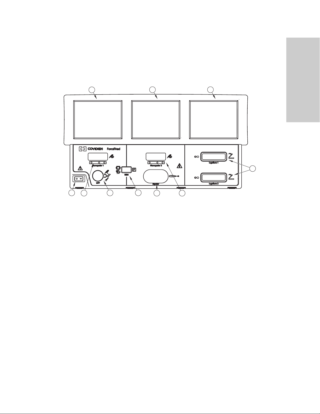
ForceTriad Energy Platform Front Panel
2
4
5
6
7
8
9
2
3
1
10
ForceTriad Energy Platform Front Panel
Overview and General Features
Monopolar 1 and Accessory Touchscreen
Monopolar 2 and Bipolar Touchscreen
LigaSure and System Tray Touchscreen
Power Switch
Monopolar-Instrument Receptacle
Universal-Footswitching-Accessory Receptacle
REM™ Patient Return Electrode Receptacle
Bipolar-Instrument Receptacle
Monopolar 2-Instrument Receptacle
LigaSure 1 and 2 Receptacles
ForceTriad Energy Platform Service Manual 1-3
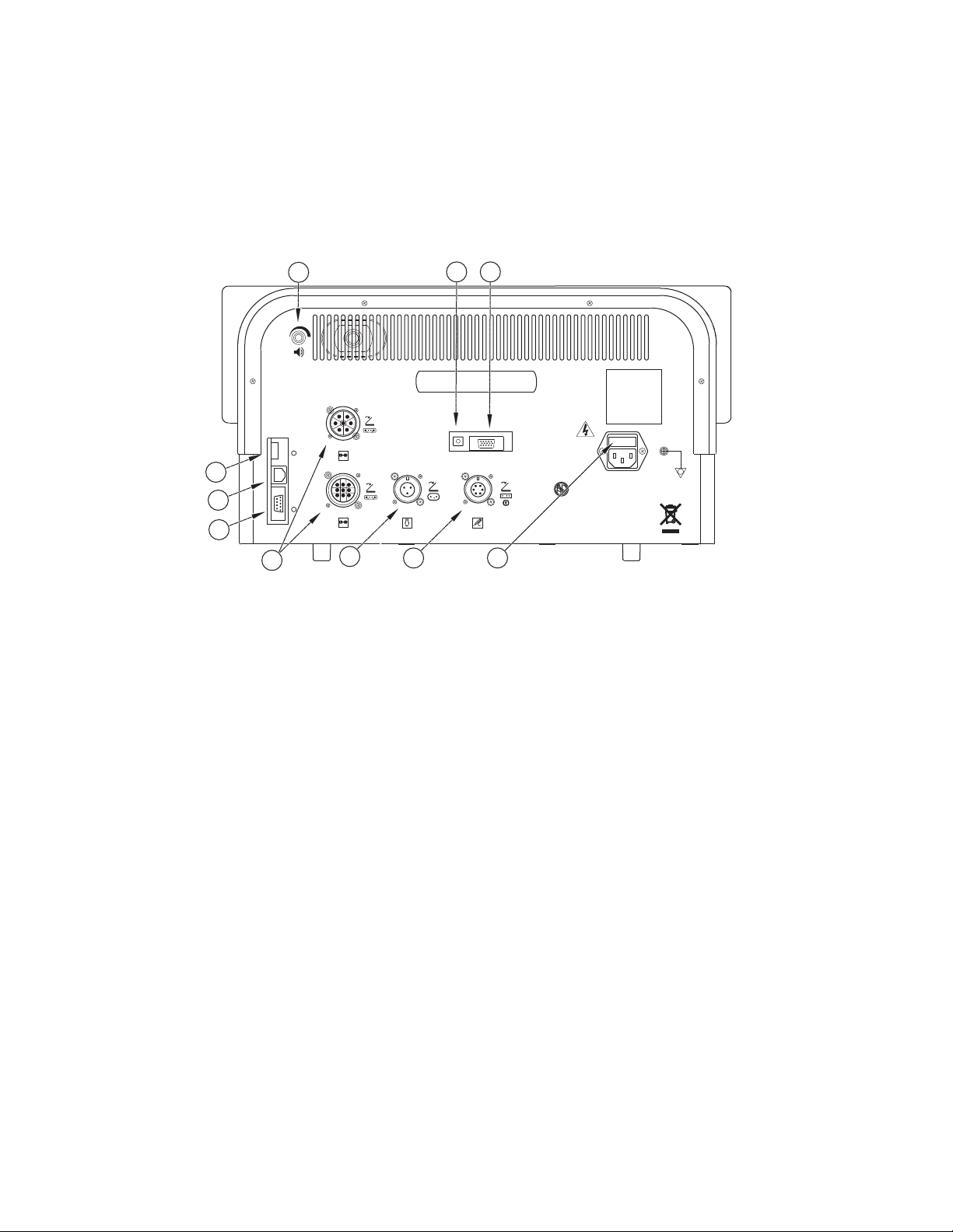
ForceTriad Energy Platform Back Panel
CAUTION
Monopolar
LigaSure 1
LigaSure 2
Bipolar
U.S. and foreign patents pending.
Warning: Risk of Fire.
Replace Fuse as Marked.
250V, F8.0A (100-240)
1
2
3
4
5
67
9
10
8
Avertissement: Risque du feu.
Remplacez les fusibles comme marqués.
250 V F8.0A (100-240)
ForceTriad Energy Platform Back Panel
USB Port
Ethernet Port
RS232 Port
LigaSure 1 and 2 Footswitch Port
Bipolar-Footswitch Receptacle
Monopolar-Footswitch Receptacle (requires adapter to connect standard
four-pin monopolar footswitch)
Fuse Port
Audio-Volume Knob
Link-Cable Port (ECG Receptacle)
Expansion Port
1-4 ForceTriad Energy Platform Service Manual
System Conventions
Touchscreens
The ForceTriad energy platform features a user-friendly interface with three touchscreens
that allow the user to control system functions. The active touchscreen or touchscreens
illuminate, and the unavailable touchscreens dim.
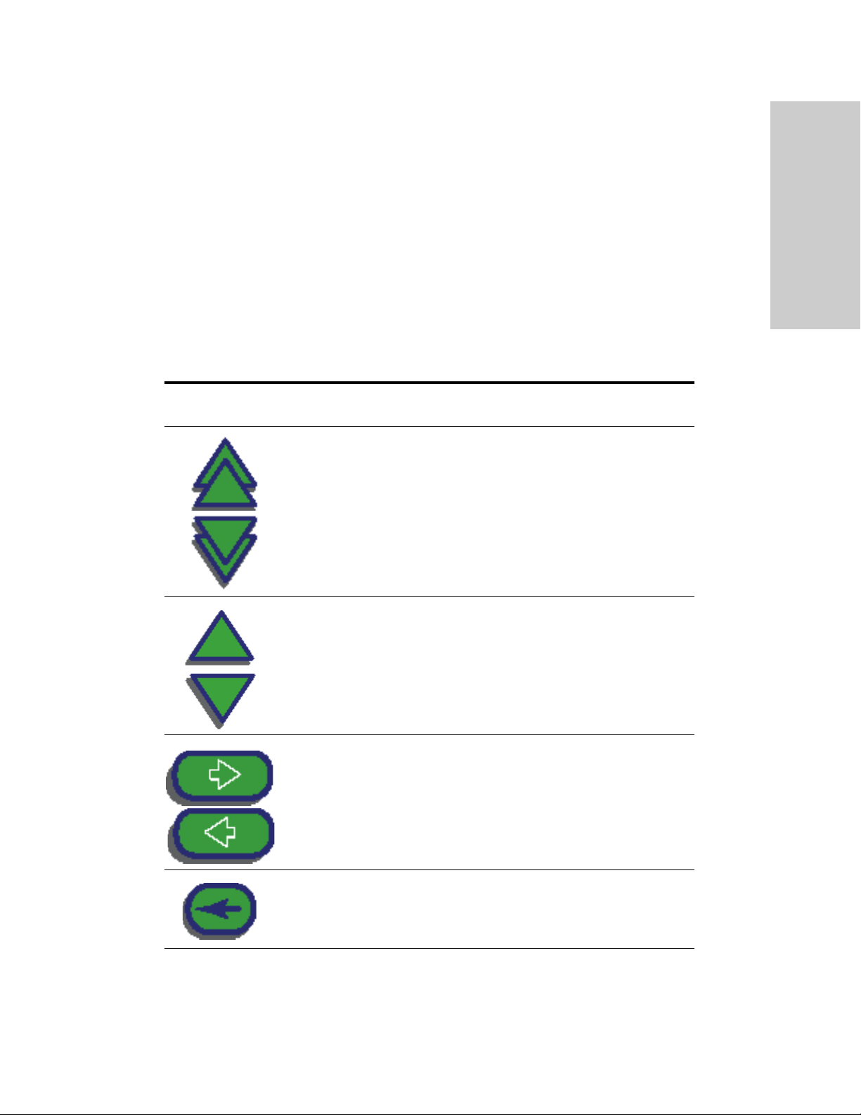
Common Symbols
Symbol Name Description
System Conventions
Overview and General Features
Page Up/Page Down
Up/Down
Next/Back
Scrolls through blocks of options that
cannot be displayed on a single screen.
Pressing once increases/decreases the
associated value or moves highlighted
selection up/down one line. Pressing and
holding scrolls up/down.
Progresses to the next screen, or returns
to the previous screen.
Back Space
ForceTriad Energy Platform Service Manual 1-5
Regresses one character.
System Conventions
Symbol Name Description
Bipolar Mute On/Off
Cancel
Enter
System Tray
Turns on/off the audio tones produced by
the system that indicate the increase or
decrease of current during a bipolar
procedure.
Cancels current screen and returns to the
previous screen.
Accepts and initiates current selections.
Accesses and adjusts system settings
including screen brightness and mainmenu options as well as a connection
indicator.
Brightness
Each selection of this button alternately
adjusts between two available brightness
settings. When maximum brightness is
reached, next selection resets to the least
bright setting.
Wrench
Selects access to the Main Menu, which
provides user-selected options for
language, appearance, and operation.
1-6 ForceTriad Energy Platform Service Manual
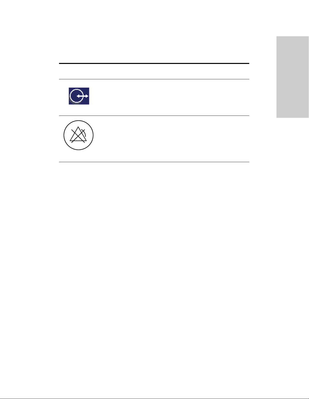
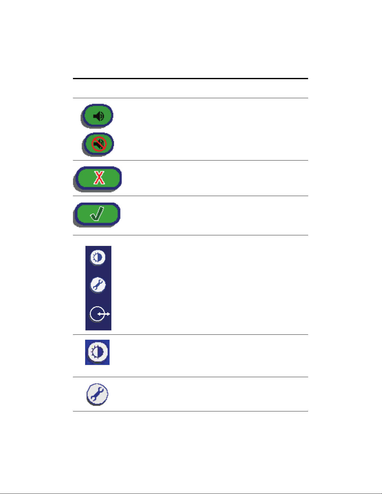
Symbol Name Description
Power Modes
Overview and General Features
Connection Indicator
Errors Disabled
Note: Additional information on symbols may be found in Chapter 4, Technical
Specifications.
Indicates active communication with
another system such as Valleylab
Exchange Remote Software System or a
third-party system.
This icon on a yellow background overlays
the screen when error warnings have
been disabled using the service menu. The
system does not alarm or give error
conditions when this symbol is activated.
Touching the screen removes the icon for
five seconds.
Power Modes
As a safety feature, simultaneous activation of multiple instruments is not possible on the
system.
Monopolar Modes
The system produces five modes of power output.
Note: To provide expected hand-piece functionality, proper insertion of the hand piece is
required. Refer to the orientation drawing on the front of the system for proper insertion
orientation.
Cut Modes
Pure cut provides a clean, precise cut in any tissue with little or no hemostasis.
Blend cut is a conventional blended waveform that provides slower cutting with
simultaneous hemostasis.
Valleylab Mode
Valleylab mode is a unique combination of hemostasis and dissection that allows the user
to slow down for more hemostasis and speed up for faster dissection. Thermal spread is
equal to or less than cut or blend modes.
ForceTriad Energy Platform Service Manual 1-7

Power Modes
Coag Modes
Fulgurate coagulates tissue by sparking from the active electrode, through air, to the
patient tissue. Because sparks may spray unpredictably from the electrode during
fulguration, using fulguration for delicate tissue or in confined areas can complicate
surgery. Accidental sparking to adjacent areas can occur as tissue at the surgical site dries
and becomes more resistant to current flow.
Spray delivers wider fulguration; penetration is shallower and the affected tissue area is
larger than with the Fulgurate mode.
Bipolar Modes
Three bipolar modes are available: low, standard, and macrobipolar.
Low delivers precision and fine control over the amount of desiccation.
Standard is a conventional bipolar output at low voltage.
Macro (macrobipolar) may be used for bipolar cutting or rapid coagulation. Power
remains constant over a wide range of tissue types.
Autobipolar
The autobipolar feature senses tissue impedance between the two bipolar electrodes,
then uses the impedance information to automatically start or stop bipolar RF energy
delivery. Optionally, the user may choose between footswitch start and auto start, or
program a delay between auto start and RF activation.
Note: When using autobipolar, the tissue in the grasp of the bipolar device must have an
impedance within 20 Ω and 1,000 Ω. The activation impedance safety feature does not
deliver RF power to the tissue if it is not within the specified range. This is a factory-set
value that cannot be reset by the user.
1-8 ForceTriad Energy Platform Service Manual

LigaSure Mode
The LigaSure tissue-fusion mode can be used on arteries, veins, pulmonary vasculature,
and lymphatics up to and including 7 mm in diameter and tissue bundles. This system
provides precise energy delivery and electrode pressure to vessels for a controlled time
period to achieve a complete and permanent fusion of the vessel lumen. The system has
been designed to produce minimal sticking, charring, or thermal spread to adjacent
tissue.
Warning
Do not attempt to fuse lung tissue with LigaSure mode or instruments.
LigaSure Instruments
The LigaSure instruments that complete the ForceTriad tissue-fusion system include
multiple reusable and single-use instruments for open and laparoscopic procedures. Each
reusable instrument requires a corresponding single-use electrode. The LigaSure function
is available only when using LigaSure instruments.
Power Modes
Overview and General Features
ForceTriad Energy Platform Service Manual 1-9


Chapter 2
Patient and Operating Room Safety
The safe and effective use of electrosurgery depends to a large degree upon
factors solely under the control of the operator. There is no substitute for a
properly trained and vigilant surgical team. It is important that the operating
instructions supplied with this or any electrosurgical equipment be read,
understood, and followed.
Electrosurgery has been used safely in millions of procedures. Before starting any
surgical procedure, the surgeon should be trained in the particular technique and
surgical procedure to be performed, should be familiar with the medical
literature related to the procedure and potential complications, and should be
familiar with the risks versus the benefits of utilizing electrosurgery in the
procedure.
ForceTriad Energy Platform Service Manual 2-1

General
General
Setting Up the System
Warning
Electric Shock Hazard Connect the system power cord to a properly grounded power
receptacle. Do not use power plug adapters.
Fire Hazard Do not use extension cords.
Patient Safety Use the system only if the power-up self-test has been completed as described in
this manual, otherwise inaccurate power outputs may result.
Warning
Hazardous Electrical Output This equipment is for use only by trained, licensed physicians.
Do not use electrosurgical equipment unless properly trained to use it in the specific procedure
being undertaken. Use of this equipment without such training can result in serious, unintended
patient injury, including bowel perforation and unintended, irreversible tissue necrosis.
Always use the lowest power setting that achieves the desired surgical effect. The active electrode
should be utilized only for the minimum time necessary in order to lessen the possibility of
unintended burn injury. Accidental and unintended burn injury has occurred during procedures in
small surgical fields and on small appendages. Pediatric applications and/or procedures performed
on small anatomic structures may require reduced power settings. The higher the current flow
and the longer the current is applied, the greater the possibility of unintended thermal damage to
tissue, especially during use on small structures.
Do not wrap the instrument cords or patient return electrode cords around metal objects. This
may induce currents that could lead to shocks, fires, or injury to the patient or surgical team.
Electric Shock Hazard Do not connect wet instruments to the energy platform. Ensure that all
instruments and adapters are correctly connected and that no metal is exposed at any connection
points.
Confirm proper power settings before proceeding with surgery. If the proper power settings are
not known, set the power to a low setting and slowly increase the power until the desired effect
is achieved. If increased power settings are requested, check the patient return electrode and all
instrument connections before making major power setting adjustments.
Contact between the active electrode and any metal greatly increases current flow and can result
in unintended surgical effect.
2-2 ForceTriad Energy Platform Service Manual

Warning
While using electrosurgery, the patient should not be allowed to come into direct contact with
grounded metal objects (e.g., surgical table frame, instrument table, etc.). If this is not possible
during certain procedures (e.g., those in which non-insulated head frames are used), use extreme
caution to maximize patient safety:
• Use the lowest power setting that achieves the desired effect.
• Place the patient return electrode as close to the surgical site as possible.
• Place dry gauze between the patient and the grounded object if possible.
• Continually monitor the contact point(s).
• Do not use metal needle monitoring electrodes.
General
Patient and Operating Room
Caution
Read all warnings, cautions, and instructions provided with this system before using.
Read the instructions, warnings, and cautions provided with electrosurgical instruments before
using. Specific instructions for electrosurgical instruments are not included in this manual.
For surgical procedures where the current could flow through delicate parts of the body, the use
of bipolar techniques may be desirable in order to avoid unwanted coagulation.
Examine all instruments and connections to the system before using. Ensure that the instruments
function as intended. Improper connection may result in arcs, sparks, instrument malfunction, or
unintended surgical effects.
Do not turn the activation tone down to an inaudible level. The activation tone alerts the surgical
team when the system is delivering RF energy.
When using a smoke evacuator in conjunction with the system, set the system volume control at
a level that ensures that the activation tones can be heard.
Connect only Covidien-approved footswitches. Using footswitches from other manufacturers may
cause equipment malfunction.
A non-functioning system may cause interruption of surgery. A backup system should be available
for use.
Studies have shown that smoke generated during electrosurgical procedures can be potentially
harmful to patients and the surgical team. These studies recommend adequately ventilating the
smoke by using a surgical smoke evacuator or other means.
a
Safety
Inadvertent activation may occur while installing, removing, or bending electrodes. Ensure that
the instrument cord is not connected to the system or that the system is OFF.
a. U.S. Department of Health and Human Services. National Institute for Occupational Safety and
Health (NIOSH). Control of Smoke from Laser/Electric Surgical Procedures. HAZARD
CONTROLS, Publication No. 96-128, September, 1996.
ForceTriad Energy Platform Service Manual 2-3

General
Notice
Connect the power cord to a properly grounded power receptacle having the correct voltage;
otherwise, product damage may result.
Important
If required by local codes, connect the system to the hospital equalization connector with an
equipotential cable.
Fire/Explosion Hazard
Warning
Explosion Hazard Do not use electrosurgery in the presence of flammable anesthetics.
Fire Hazard Do not place active instruments near or in contact with flammable materials (such
as gauze or surgical drapes). Electrosurgical instruments that are activated or hot from use can
cause a fire. When not in use, place electrosurgical instruments in a safety holster or safely away
from patients, the surgical team, and flammable materials.
Fire Hazard Sparking and heating associated with electrosurgery can be an ignition source.
Keep gauze and sponges wet. Keep electrosurgical electrodes away from flammable materials
and oxygen (O
Use of electrosurgery in O2 rich environments increases the risk of fire. Therefore, take measures
to reduce the O2 concentration at the surgical site.
Avoid enriched O2 and nitrous oxide (N2O) atmospheres near the surgical site. Both O2 and N2O
support combustion and may result in fires and burns to patients or surgical personnel.
If possible, stop supplemental oxygen at least one minute before and during use of electrosurgery.
Do not activate the system until flammable vapors from skin prep solutions and tinctures have
dissipated.
Avoid the accumulation of naturally occurring flammable gases that may accumulate in body
cavities such as the bowel.
Prevent pooling of flammable fluids and the accumulation of flammable or oxidizing gases or
vapors under surgical drapes or near the surgical site.
Tissue buildup (eschar) on the tip of an active electrode may create embers that pose a fire
hazard, especially in oxygen enriched environments. Keep the electrode clean and free of all
debris.
Facial and other body hair is flammable. Water soluble surgical lubricating jelly may be used to
cover hair close to the surgical site to decrease flammability.
Verify that all anesthesia circuit connections are leak free before and during use of electrosurgery.
) enriched environments.
2
2-4 ForceTriad Energy Platform Service Manual

Warning
Fire Hazard During Oropharyngeal Surgery
Verify endotracheal tubes are leak free and that the cuff seals properly to prevent oxygen leaks.
If an uncuffed tube is in use, pack the throat with wet sponges around the uncuffed tube, and be
sure to keep sponges wet throughout the procedure.
Question the need for 100% O2 during oropharyngeal or head and neck surgery.
If necessary, scavenge excess O
with separate suction.
2
ForceTriad Energy Platform
General
Patient and Operating Room
Warning
Each instrument receptacle on this system is designed to accept only one instrument at a time.
Follow the instructions provided with electrosurgical instruments for proper connection and use.
Caution
Do not stack equipment on top of the system or place the system on top of electrical equipment.
This is an unstable configuration and does not allow for adequate cooling.
Provide as much distance as possible between the system and other electronic equipment (such as
monitors). Do not cross or bundle electronic-device cords. This system may cause interference
with other electronic equipment.
Active Instruments
Caution
Read the instructions, warnings, and cautions provided with electrosurgical instruments before
using. Specific instructions for electrosurgical instruments are not included in this manual.
Inspect instruments and cords for breaks, cracks, nicks, and other damage before every use. If
damaged, do not use. Damaged instruments or cords may result in injury or electrical shock to the
patient or surgical team.
Safety
Use only instruments that can withstand the maximum output (peak) voltage for each output
mode as listed in Chapter 4, Technical Specifications. Using an instrument with a voltage rating
that is lower than the maximum output voltage may result in injury to the patient or the operator,
or damage to the instrument.
All Covidien instruments have voltage ratings that are greater than the maximum output voltages
in the system and are thus fully compatible.
Information on voltage ratings for non-Covidien instruments should be obtained from the
instrument’s manufacturer.
ForceTriad Energy Platform Service Manual 2-5

General
Implanted Electronic Devices (IEDs)
IEDs include, but are not limited to, pacemakers, neurostimulators, implantable
cardioverter defibrillators (ICDs), ventricular assist devices (VAD), spinal cord stimulators,
cochlear implants, infusion pumps and bone growth stimulators.
Warning
If the patient has an implanted electronic device (IED), contact the IED manufacturer for
instructions before performing an electrosurgical or tissue-fusion procedure. Electrosurgery or
tissue fusion may cause multiple activations of ICDs, or interfere with the intended function of
other IEDs.
If the patient has an implanted electronic device (IED), contact the IED manufacturer for
instructions before performing an electrosurgical or tissue-fusion procedure. Electrosurgery or
tissue fusion may cause multiple activations of ICDs, or interfere with the intended function of
other IEDs.
After Surgery
Warning
Electric Shock Hazard Always turn off and unplug the ForceTriad energy platform before
cleaning.
Caution
Do not reprocess, reuse or resterilize instruments labeled “disposable” or “single use only.”
Notice
Do not clean the system with abrasive cleaning or disinfectant compounds, solvents, or other
materials that could scratch the panels or damage the system.
2-6 ForceTriad Energy Platform Service Manual

Monopolar
Warning
Simultaneously activating suction/irrigation and electrosurgical current may result in increased
arcing at the electrode tip, burns to unintended tissues, or shocks and burns to the surgical team.
Some surgeons may elect to “buzz the hemostat” during surgical procedures. It is not
recommended, and the hazards of such a practice probably cannot be eliminated. Burns to the
surgeon’s hands are possible. To minimize the risk take these precautions:
• “Buzz the hemostat” below hand level (as close as possible to the patient) to reduce the
opportunity for current to follow alternate paths through the surgeon’s hands.
• Do not “buzz the hemostat” with a needle electrode.
• Do not lean on the patient, the table, or the retractors while buzzing the hemostat.
• Activate cut rather than coag. Cut has a lower voltage than coag.
• Firmly grasp as much of the hemostat as possible before activating the system. This disperses
the current over a larger area and minimizes the current concentration at the finger tips.
• Use the lowest power setting possible for the minimum time necessary to achieve hemostasis.
• Activate the system after the instrument makes contact with the hemostat. Do not arc to the
hemostat.
• When using a coated- or nonstick-blade electrode, place the edge of the electrode against the
hemostat or other metal instrument.
Monopolar
Patient and Operating Room
Safety
Patient Return Electrodes
Warning
Do not attempt to use patient return electrodes that disable the REM system. The REM system
functions correctly only with contact quality monitoring (CQM) split-style patient return
electrodes. Any other patient return electrode products may cause patient injury or product
damage.
The safe use of monopolar electrosurgery requires proper placement of the patient return
electrode. To avoid electrosurgical burns beneath the patient return electrode, follow all directions
provided with the product.
Do not cut a patient return electrode to reduce its size. Patient burns due to high current density
may result.
A patient return electrode is not necessary in bipolar or LigaSure procedures.
To avoid patient burns, ensure that the patient return electrode firmly and completely contacts
the skin. Always check the patient return electrode periodically and after the patient is
repositioned and during procedures involving long periods of activation.
Use of duty cycles greater than 25% (10 seconds active followed by 30 seconds inactive) increases
the risk that heat build-up under a return electrode may be high enough to injure the patient. Do
not continuously activate for longer than one minute.
ForceTriad Energy Platform Service Manual 2-7

Monopolar
Notice
Capacitive pads and other non-CQM patient return electrodes may not work with the system.
Important
A statement of compatibility from the CQM patient return electrode manufacturer should be
obtained prior to the use of a non-Covidien CQM patient return electrode.
Inadvertent Radio Frequency (RF) Burns
Warning
Electrodes and probes used with monitoring, stimulation, and imaging devices (or similar
equipment) can provide a path for high-frequency current even if the electrodes or probes are
isolated at 50 Hz to 60 Hz, insulated, and/or battery operated.
Do not use needles as monitoring electrodes during electrosurgical procedures. Inadvertent
electrosurgical burns may result.
To reduce the risk of an inadvertent electrosurgical burn at the electrode or probe site, place the
electrode and/or probe as far away as possible from the electrosurgical site and/or patient return
electrode. Protective impedances (resistors or RF inductors) installed in the monitoring leads may
reduce the risk of such burns. Consult the hospital biomedical engineer for further information.
In some circumstances, the potential exists for alternate site burns at points of skin contact (e.g.,
between the arm and the side of the body). This occurs when electrosurgical current seeks a path
to the patient return electrode that includes the skin-to-skin contact point. Current passing
through small skin-to-skin contact points is concentrated and may cause a burn. This is true for
ground referenced and isolated output electrosurgical energy systems.
To reduce the potential for alternate site burns, do one or more of the following:
• Avoid skin-to-skin contact points, such as fingers touching leg or knee touching knee when
positioning the patient.
• Place insulation, such as dry gauze or towel, between contact points to ensure that contact
does not occur.
• Position the patient return electrode to provide a direct current route between the surgical site
and the return electrode which avoids skin-to-skin contact areas.
• In addition, place patient return electrodes according to the manufacturer’s instructions.
2-8 ForceTriad Energy Platform Service Manual

Laparoscopic Procedures
Laparoscopic Procedures
Warning
For laparoscopic procedures, be alert to these potential hazards:
• Laparoscopic surgery may result in gas embolism due to insufflation of gas in the abdomen.
• The electrode tip may remain hot enough to cause burns after the electrosurgical current is
deactivated.
• Inadvertent activation or movement of the activated electrode outside of the field of vision may
result in injury to the patient.
• Localized burns to the patient or physician may result from electrical currents carried through
conductive objects (such as cannulas or scopes). Electrical current may be generated in
conductive objects through direct contact with the active electrode, or by the active instrument
(electrode or cable) being in close proximity to the conductive object.
• Do not use hybrid trocars that have a non-conductive locking anchor placed over a conductive
sleeve. For the operative channel, use all-metal or all-plastic systems. At no time should
electrical energy pass through hybrid systems. Capacitive coupling of RF current may cause
unintended burns.
• When using laparoscopic instrumentation with metal cannulas, the potential exists for
abdominal-wall burns to occur due to direct electrode contact or capacitive coupling of RF
current. This is most likely to occur in instances where the system is activated for extended
periods at high power levels inducing high current levels in the cannula.
• Ensure that the insulation of single-use and reusable laparoscopic instrumentation is intact and
uncompromised. Compromised insulation may lead to inadvertent metal-to-metal sparking and
neuromuscular stimulation and/or inadvertent sparking to adjacent tissue.
• Do not activate electrodes while in contact with other instruments as unintended tissue injury
may occur.
Patient and Operating Room
Safety
Do not activate the system in an open-circuit condition. To reduce the chances of unintended
burns, activate the system only when the active electrode is near or touching the target tissue.
• Use the lowest power setting that achieves the desired surgical effect and use a low-voltage
waveform (Pure Cut, Blend, or Valleylab mode) to lessen the potential for the creation of
capacitive currents.
• Carefully insert and withdraw active electrodes from cannulas to avoid possible injury to the
patient or damage to the devices.
Covidien recommends against the use of laparoscopic surgery on pregnant patients.
ForceTriad Energy Platform Service Manual 2-9

Bipolar
Bipolar
Caution
Bipolar instruments must be connected to the bipolar instrument receptacle only. Improper
connection may result in inadvertent system activation.
LigaSure
Warning
LigaSure instruments are intended for use ONLY with the ForceTriad energy platform and the
LigaSure vessel sealing system. Use of these instruments with other Covidien generators or with
generators produced by other manufacturers may not result in electrical output for which these
instruments were designed and thus may not result in the desired clinical effect.
If the seal-complete tone has not sounded, an optimal seal may not have been achieved.
Reactivate the RF energy until a seal-complete tone is heard.
The LigaSure tissue-fusion function has not been shown to be effective for tubal sterilization or
tubal coagulation for sterilization procedures. Do not use this function for these procedures.
Use caution during surgical cases in which patients exhibit certain types of vascular pathology
(atherosclerosis, aneurysmal vessels, etc.). For best results, apply the seal to unaffected
vasculature.
Do not activate the system in the LigaSure mode until the tissue-fusion instrument has been
applied with the proper pressure. Activating the system before this is done results in an improper
seal and may increase thermal spread to tissue outside the surgical site.
Tissue fusion requires the application of RF energy and pressure from the instrument. Tissue to be
sealed must be firmly grasped between the instrument jaw electrodes. Tissue in the jaw hinge or
outside the instrument jaw will not be sealed even if thermal blanching occurs.
Do not use LigaSure instruments on vessels in excess of 7 mm in diameter.
LigaSure instruments that require single-use electrodes must be used with the correct electrode
type. Use of these instruments with any other electrodes could result in injury to the patient or
surgical team, or cause damage to the instrument.
Conductive fluids (e.g, blood or saline) in direct contact with LigaSure instruments or in close
proximity may carry electrical current or heat, which may cause unintended surgical effects or
burns.
Caution
Energy based devices, such as electrosurgical pencils or ultrasonic scalpels, that are associated
with thermal spread should not be used to transect seals.
Avoid placing fingers in the handle ratchet mechanism or between the ring handles or jaws as
applicable depending on the type of instrument. Injury to the user may result.
2-10 ForceTriad Energy Platform Service Manual

LigaSure in Laparoscopic Procedures
Warning
For laparoscopic procedures, be alert to these potential hazards:
• The external surfaces of the LigaSure instrument jaws may remain hot enough to cause burns
after the RF current is deactivated.
• Inadvertent activation or movement of the activated LigaSure instrument outside of the field of
vision may result in injury to the patient.
• Do not activate the instrument while the instrument jaws are in contact with, or in close
proximity to, other instruments including metal cannulas, as localized burns to the patient or
physician may occur.
• Do not activate the LigaSure function in an open circuit condition. Activate the system only
when the instrument is near or in direct contact with the target tissue to reduce the possibility
of unintended burns.
• Carefully insert and withdraw LigaSure instruments from cannulas to avoid possible damage to
the devices and/or injury to the patient.
Servicing
Patient and Operating Room
Safety
Servicing
Warning
Electric Shock Hazard Do not remove the system cover. Contact qualified personnel for service.
Notice
Refer to Chapter 9, Maintenance and Repair for maintenance recommendations and function and
output power verification procedures.
Shunt Cords
Warning
Some surgical instruments (e.g., colonoscopes) may allow substantial leakage current that could
burn the surgeon. If the instrument manufacturer recommends the use of a shunt cord (s-cord) to
direct the current back to the system, you must also use a E0507-B adapter. To avoid a REM
alarm, you must use a REM Polyhesive™ patient return electrode with the E0507-B adapter.
ForceTriad Energy Platform Service Manual 2-11

Conductive Fluid in the Surgical Site
Conductive Fluid in the Surgical Site
Warning
When this system is used in procedures where conductive fluid (saline or lactated Ringers) is
introduced into the surgical site for distention or to conduct RF current, higher than normal
currents (greater than one amp) may be produced. In this situation, use one or more adult-size
return electrodes. Do not use return electrodes labeled for children, infants, babies, neonatal use,
or pediatric use.
Use of duty cycles greater than 25% (10 seconds active followed by 30 seconds inactive) increases
the risk that heat build-up under a return electrode may be high enough to injure the patient. Do
not continuously activate for longer than one minute.
2-12 ForceTriad Energy Platform Service Manual

Chapter 3
Principles of Operation
This chapter provides detailed information about how the ForceTriad energy
platform functions and how the internal components interact.
This chapter includes the following information:
• A block diagram that illustrates how the system functions
• A general description of how the system works
• Detailed descriptions of the circuitry for the printed PCBAs
ForceTriad Energy Platform Service Manual 3-1

Block Diagram
Block Diagram
3-2 ForceTriad Energy Platform Service Manual

Block Diagram key to numbers
1 ASSY CABLE CHASSIS-GND NHP 23 CABLE DISPLAY POWER FORCETRIAD
2 CABLE AC FILTER-SWITCH FORCETRIAD 24 CABLE UFAP SENSE FORCETRIAD
3 CABLE PANEL-SWITCH FORCETRIAD 25 CABLE ETHERNET 27 INCH
4 CABLE AC SWITCH HVDC FORCETRIAD 26 CABLE FLEX LCD-DISPLAY FORCETRIAD
5 CABLE HVDC-LVPS FORCETRIAD 27 CABLE FLEX LCD-DISPLAY FORCETRIAD
6 CABLE RF-LVPS FORCETRIAD 28 CABLE FLEX LCD-DISPLAY FORCETRIAD
7 CABLE SPEAKER FORCETRIAD 29 CABLE LCD-INVERTER FORCETRIAD
8 CABLE LIGASURE 1 FTSW FORCETRIAD 30 CABLE LCD-INVERTER FORCETRIAD
9 CABLE LIGASURE 2 FTSW FORCETRIAD 31 CABLE LCD-INVERTER FORCETRIAD
Block Diagram
10 CABLE REM SR-RF FORCETRIAD 32 CABLE RIBBON SCANNER FORCETRIAD (LIG 1)
11 CABLE MONO OUT FORCETRIAD 33 CABLE RIBBON SCANNER FORCETRIAD (LIG 2)
12 CABLE RF-STEERING FORCETRIAD 34 CABLE RIBBON SCANNER FORCETRIAD (MONO 1)
13 CABLE AUTOBIPOLAR FORCETRIAD 35 CABLE RIBBON SCANNER FORCETRIAD (LIG 2)
14 CABLE LIG 1 OUTPUT FORCETRIAD 36 INTEGRAL TO LCD ASSEMBLY
15 CABLE LIG 2 OUTPUT FORCETRIAD 37 INTEGRAL TO LCD ASSEMBLY
16 CABLE BIP OUTPUT FORCETRIAD 38 INTEGRAL TO LCD ASSEMBLY
17 CABLE BIPOLAR SENSE FORCETRIAD 39 CABLE UFP POWER FORCETRAID
18 CABLE ACTIVE BIPOLAR SENSE 40 ASSY CABLE REM RETURN FORCETRIAD
19 CABLE MONO 1 OUTPUT 41 CABLE RF-FOOTSWITCH FORCETRIAD
20 CABLE MONO 2 OUTPUT 42 CABLE RF SHIELD FORCETRIAD
21 CABLE DISPLAY POWER 43 not orderable
22 CABLE MONO MODE FORCETRIAD 44 JUMPER CABLE FAN FEP
Principles of Operation
ForceTriad Energy Platform Service Manual 3-3

Functional Overview
Functional Overview
The ForceTriad energy platform is a combination of a full-featured general-surgery
electrosurgical unit and a LigaSure vessel sealing system. The monopolar and bipolar
sections of the system are isolated electrosurgical outputs that provide the appropriate
power for cutting, desiccating, and fulgurating tissue during monopolar and bipolar
surgery. The LigaSure section of the system provides power for vessel sealing.
During monopolar electrosurgery, radio frequency (RF) current flows from the system to
an active electrode, which delivers the current to the patient. The resistance to the
current, provided by the patient’s tissue and/or the air between the active electrode and
the tissue, produces the heat that is necessary for the surgical effect. The RF current flows
from the active electrode, through the patient’s body tissue to the return electrode,
which recovers the current and returns it to the system.
The LigaSure vessel sealing system provides precise energy delivery and electrode pressure
to vessels for a controlled time period to achieve a complete and permanent fusion of the
vessel lumen.
TissueFect Tissue Sensing Technology
The system automatically senses resistance and adjusts the output voltage to maintain a
consistent tissue effect across different tissue impedance. This adjustment is based on the
selected mode, the power setting, and the level of tissue resistance.
REM Contact Quality Monitoring System
The system uses the REM Contact Quality Monitoring system to monitor the quality of
electrical contact between the patient return electrode and the patient. The REM system
is designed to minimize the risk of burns at the return electrode site during monopolar
electrosurgery.
When the user connects a REM Polyhesive patient return electrode to the patient return
electrode receptacle, they activate the REM system. When the user activates monopolar
output, the system connects the patient return electrode path. If the user activates
bipolar output while a return electrode is connected to the patient, the return electrode
circuit is deactivated automatically to eliminate the possibility of current dispersal.
The REM system continuously measures resistance at the return electrode site and
compares it to a standard range of safe resistance (between 5
minimizing intermittent false alarms that could result from small changes in resistance.
The REM system also adapts to individual patients by measuring the initial contact
resistance (baseline resistance) between the patient and the patient return electrode. If
the tissue impedance at the return electrode decreases during electrosurgery, the REM
system resets the baseline resistance.
Ω and 135 Ω), thus
3-4 ForceTriad Energy Platform Service Manual

High-Voltage DC (HVDC PCBA) Power Supply Principles of Operation
REM Alarm Activation
The REM Alarm indicator flashes red, a tone sounds, and the system stops producing
output power when either of the following occurs:
• The measured resistance is below 5 Ω or above 135 Ω, the limits of the standard
range of safe resistance.
• An increase in contact resistance is greater than 40% from the initial measurement
(baseline resistance).
The REM Alarm indicator remains illuminated red until the condition causing the alarm is
corrected. Then, the indicator illuminates green and RF output is enabled.
Electrodes Without the REM Safety Feature
Return electrodes without the REM safety feature cannot be used on the system.
High-Voltage DC (HVDC PCBA) Power Supply
Principles of Operation
The HVDC power supply regulates an output DC voltage to a desired level that is
proportional to a 0 V to 5 V analog logic signal called Voltage Control (ECON). The AC
input range is 85 VAC to 264 VAC with line frequencies from 47 Hz to 63 Hz. The HVDC
can be simplified into two sections, the AC section and DC section.
The AC section rectifies the AC input into the rectified +Bus and –Bus voltages. For line
voltages of 150 VAC or less, the rectified AC voltage is doubled. The rectified voltage is
monitored and is flagged if the voltage starts to drop too low or if the rectified voltage
exceeds 400 VDC. As a safety feature, the HVDC shuts down when it exceeds 400 VDC.
The AC section also incorporates a soft start circuit that reduces the inrush AC current at
power up.
The DC section is a phase-shifted full-bridge topology and uses a Pulse Width Modulator
(PWM). The DC section consists of limits that help protect the HVDC from fault
conditions.
These limits include over voltage, over current, over power, and short circuit. Each limit
sends a flag to the controller PCBA if it is triggered and shuts down the HVDC. Another
feature of the HVDC is an active discharge circuit; this circuit places a load across the
output. This allows the output of the HVDC to discharge quickly no matter what the load
attached to the HVDC.
Principles of Operation
ForceTriad Energy Platform Service Manual 3-5

RF PCBA Principles of Operation
RF PCBA Principles of Operation
The primary purpose of the ForceTriad RF PCBA is to convert the DC voltage coming from
the HVDC PCBA into a 470 kHz RF signal that is sent to the Steering Relay PCBA to be
distributed to the appropriate output.
A push-pull topology is used to accomplish this voltage conversion. Two gate-drive
signals that are 180° out of phase are used to drive the high-voltage Field Effect
Transistors (FETs), called T ON and T ON 180. The gate-drive signals turn on each of the
FETs at opposite times to deliver a waveform at the specified power requested from the
user.
The RF PCBA is capable of several different outputs ranging from 5.5 A RMS in LigaSure
tissue fusion modes to over 7 KVpp in coag modes. Relays throughout the RF PCBA
switch in the appropriate tuning elements required to achieve these various outputs.
Primary and redundant sense circuits detect the RF output voltage and current. An
accurate scaled down AC voltage representative of each of these is sent to the controller
PCBA, which in turn keeps the output at levels appropriate for the mode in use.
Four sense relays for each circuit correspond to specific modes and switch in voltage
dividers tuned to divide the output signals to levels that are manageable for the controller
PCBA.
Three relays for each voltage sense circuit divide down the output voltages from 425 Vpk
- 5000 Vpk to around 1 Vpk, depending on the mode selected by the user. The current
sensors use one relay for each circuit; this relay activates for currents higher than 1 A
RMS. The sensor signals are passed through a multiplier which uses a gain control signal
from the controller PCBA.
After this multiplier stage, the signal is filtered and routed to the controller PCBA. RF
voltage and current foldback circuits use the ranges selected on the sensors to determine
if a limit has been reached. These circuits fold back the ECON signal going to the HVDC,
reducing the DC output to the RF PCBA. This in turn reduces the RF output amplitude.
REM
The Return Electrode Monitor (REM) circuit monitors the resistance between the two
return areas on a REM electrode using an 80 kHz signal generated by the controller
PCBA.
Autobipolar
The Autobipolar (ABP) circuit consists of an 80 kHz signal, also generated by the
controller PCBA. It is used to monitor the bipolar output impedance.
Leakage Current Monitor
The RF PCBA also features a leakage current monitor circuit, which measures the active
and return of the system and puts out a DC voltage that represents the difference
3-6 ForceTriad Energy Platform Service Manual

RF PCBA Principles of Operation
between the two. If this voltage exceeds a limit, the RF is folded back to prevent excess
leakage current.
Sensor Circuit
The sensor circuit provides RF output voltage and current monitoring to software in order
to deliver the correct energy dosage during a surgical procedure. Two identical sensory
circuit paths, composed of a primary and backup, are implemented to provide fail-safe
mitigation in the event of circuit failure.
Because each primary and backup sensor circuit mirrors the other, the sensed output
voltages, which are monitored by software, are equal when the sensory system maintains
proper operation. In the event of a failure of the primary or backup sense circuit,
dissimilar outputs are present and software detection stops delivery of RF. The user is
notified with an error message displayed on the front panel of the ForceTriad energy
platform.
Each primary and backup sensory circuit consists of four processing elements to ensure
that the correct RF is delivered. In the description that follows, the primary sensory path is
identified for the voltage-sense circuitry, with reference designation only provided to the
backup circuit.
Backup-circuit operation is identical to the primary circuit that is described here. RF
current-sense circuit process is symmetrical to the voltage-sense description in that it also
uses four processing elements. The only notable difference between voltage and current
sensing is the different transfer gains required to adequately address the dynamic range
of individual system operating modes.
First: Transformer T6, along with resistors R110 and R119, provide RF output voltage
monitoring by generating a proportionately scaled, secondary-sense voltage, which is
correlated to the delivered RF output voltage. Backup referenced components are T1,
R95, and R111.
Principles of Operation
Second: Coupled to the secondary of transformer T6, a software-controlled switchedpad network is implemented to provide proper impedance scaling to address the
dynamic sensory range required for all operating modes of the system.
This pad-impedance switched network is used to develop the proportionately scaled
secondary sense voltage of T6. Resistors R103 and R107 provide the initial impedance
termination, paralleled by resistor-paired components R104 and R105, R94 and R106,
and R85 and R100, which are switched independent on the selected system cut, blend,
and coag operating modes respectively.
Paired-resistor switching is accomplished by electronic-switch components RL12, RL11,
and RL10 respectively. Backup referenced-terminating components are R89 and R93;
paired components are R90 and R91, R88 and R92, and R81 and R84; and switch
components are RL9, RL8, and RL7, which are used respectively.
Third: The Pad network output of T6 is then differentially fed to a gain control module,
U18, which provides continuous gain control to normalize the sensed voltage output,
independent of system operating modes and delivered RF power levels.
Amplifier, U19, buffers the signal received from software which is used to precisely
control the gain of U18, while amplifier U17 provides a scaled differential-output voltage,
ForceTriad Energy Platform Service Manual 3-7

Steering Relay PCBA Principles of Operation
a result of U18 gain processing. Backup referenced components are gain-control module
U40, buffer amp U31, and difference amp U30 respectively.
Fourth: The output of amplifier U17 is now delivered to the last stage for sensory-signal
processing. An anti-alias filter device, U16, receives the difference signal from U17. The
last stage of sensor processing provides a benefit to the RF-monitored output; it increases
the accuracy of the delivered RF by minimizing noise to the sensed signals. Backup
components U29, R190, and R216 are used.
Steering Relay PCBA Principles of Operation
To accommodate the need for high isolation between the patient and ground-referenced
voltages during use, the ForceTriad Steering Relay PCBA design incorporates several
different types of relays designed for very high voltage standoff. In addition, cut-outs on
the PCBA increase distances at strategic locations to help reduce creepage issues.
Multiple functions are performed by the Steering Relay PCBA. The main function is to
route the 470 kHz from the RF PCBA to one of the six outputs. The outputs are as
follows: LigaSure 1, LigaSure 2, Bipolar, Mono 1, Mono 2, and Footswitch Controlled
outputs
Because only one output can be active at any given time, the Steering Relay PCBA plays
an important role in maintaining the isolation between all the outputs and their
respective circuits. During mono and footswitch modes, a return path, called Mono
return, is required.
Mono return is monitored with a Return Electrode Monitor (REM) circuit. This circuit
monitors the resistance between the two return areas on a REM electrode. The actual
REM circuit is on the RF PCBA, but this 80 kHz signal is routed through the Steering Relay
PCBA to the Mono return.
Another signal that is routed from the RF PCBA to the Steering Relay PCBA is the
Autobipolar (ABP) signal. This 80 kHz signal monitors the bipolar output impedance.
Another important function of the Steering Relay PCBA is hand-switching detection. The
circuits used to detect hand-switching requests are powered from individual, highly
isolated power supplies.
These power supplies use transformers that convert ground referenced +12 V to an
isolated +8 V or +5 V, each referenced to its corresponding output. Five handswitching
power supplies are available: LigaSure 1, LigaSure 2, Bipolar, Mono 1, and Mono 2. When
an active hand-switch signal is detected, the detection signal is transferred across an
optocoupler and is sent to the microprocessor.
The final function of this PCBA is footswitch and bipolar sense. These circuits determine if
an instrument is connected to any of the receptacles.
3-8 ForceTriad Energy Platform Service Manual

Circuit Descriptions for the ForceTriad Display PCBA
Circuit Descriptions for the ForceTriad Display
PCBA
Hotlink Transceiver U1
The Cypress Hotlink II transceiver U1 handles all communications between the Display
PCBAs Field Programmable Gate Array (FPGA) U28 and the controller PCBA. A single IC
handles bi-directional communication.
Liquid Crystal Display (LCD) Driver Inside the FPGA U28
The LCD driver receives video data from the controller PCBA and outputs it to the
displays. Data is written into a 16-pixel deep First In/First Out (FIFO) when received from
the serial link. Data is read out of the FIFO and presented to the displays at the pixel rate.
For the ForceTriad energy platform, this yields a display refresh rate of ~46 Hz. In either
case, the pixel rate must be derived from the receive clock to keep the display output in
sync with the display data generation on the controller PCBA and prevent overflowing or
under flowing of the pixel FIFO.
Touchscreen Driver
The touch-screen driver reads user input from the touchscreens. Three touchscreens are
attached to the Display PCBA, each through its own five-wire interface. The touchscreen
driver polls each screen in turn to determine whether the user is pressing on it. If so, the
X and Y position of the touch are detected.
On the ForceTriad Display PCBA, load switching FETs are used to drive voltages onto the
four electrical-drive connections, and the voltage on the sense connection is read by an
Analog Digital Converter (ADC) U4. The drive circuitry normally drives +3.3 V to all four
drive connections, while the sense connection is pulled weakly to ground.
To measure an X coordinate, the FPGA applies 3.3 V to the upper-right and lower-right
corners of the touch screen, and ground to the upper-left and lower-left corners. The
ADC reads the voltage on the sense line and sends it to the FPGA as a digital value. The
FPGA stores this value in the touch-screen register. The FPGA then measures a Y
coordinate by applying 3.3 V to the upper-right and lower-right corners, and ground to
the lower-left and lower-right corners. The ADC reads the voltage on the sense line and
sends it to the FPGA as a digital value. The FPGA stores this value in the touch-screen
register along with the X-coordinate value and the address of the touchscreen that has
been touched. The register data is sent to the Controller which updates the display
image.
Principles of Operation
ForceTriad Energy Platform Service Manual 3-9

Footswitch/Audio PCBA Circuitry Description
Barcode Driver
The Display PCBA supports communication with four barcode readers through a quadUniversal Asynchronous Receiver/Transmitter (UART) U14. One channel of the serialinterface side of the UART is connected to each barcode reader, while the control side is
connected to the display FPGA.
The barcode driver reads data bytes out of the UART as they are received from the
barcode readers and sends them to the controller PCBA. It also writes data and control
bytes to the UART as specified by the controller PCBA.
Power Supply
The power supply is dual DC to DC converter U16. The power supply has an input of
5 V and converts it down to 3.3 V and 1.8 V outputs.
Footswitch/Audio PCBA Circuitry Description
Overview
The primary function of the audio circuitry is to receive commands from the Interface
Control Logic (ICL) FPGA on the controller PCBA through a serial, two-wire SMBus data
link. The FPGA on this PCBA processes that data to determine three parameters; wave
file, volume, and duration.
Based on these parameters, the FPGA accesses corresponding parallel data from flash
memory, serializes it and passes it out to the DAC. Control data is also passed to the DAC
that sets the volume level of the output-amplifier stage. Footswitch data is collected and
sent to the controller PCBA as well.
Finally, the expansion port has an RS-232 and ECG/blanking relay interface that connects
directly to the controller PCBA and DAC controlled by this FPGA.
3-10 ForceTriad Energy Platform Service Manual

Footswitch/Audio PCBA Circuitry Description
Power Supplies
This PCBA requires 2 power supplies: 5 V and 12 V. From those input voltages it also
generates 2.5 V, 3.3 V, and isolated supplies of +12 V, -12 V and +5 V. 5 V and 12 V are
delivered to this PCBA through the RF PCBA connector.
The 2.5 V and 3.3 V supplies are regulated down from the 5 V supply on this PCBA. The
5 V rail should draw approximately 100 mA. The 12 V rail should draw approximately
500 mA at full volume with no expansion port peripherals connected.
The 12 V supply is used by the audio amplifier, TPA1517, and also generates all of the
isolated-power supplies. The isolated-power supply can source approximately 250 mA on
each, +12 V ISO and -12 V ISO, and 500 mA on +5 V ISO.
Communications
All communications between the controller PCBA and the Footswitch/Audio PCBA are
conducted over a two-wire System Management Bus (SMBus). The master of this bus is
the controller PCBA.
Audio Data
Three commands can be received from the controller PCBA; reset, parameter write and
parameter read. The reset command resets all internal-state machines inside the FPGA. It
also immediately stops a running audio stream. The parameter commands allow the
controller to write and read three internal parameters that control sending out audio
data.
These parameters are: wave file, duration, and volume.
The wave-file parameter selects a particular wave file in the flash memory by selecting a
base memory address from a look up table.
The duration parameter selects how many times to repeat the wave file. Since each wave
file is a fixed length, that file can be repeated up to 30 times, or it can be told to be sent
out continuously until another command is received.
Finally, the volume parameter simply selects a volume level between 0 (mute) and 1024
(highest volume, approximately 60 dBA).
When a command is received, the FPGA processes that command only once. For
example, if a particular wave file is selected to be played twice, the FPGA plays that wave
file twice and then stop until a new command is received. If a wave file is to be played
continuously, it can be set using the duration parameter.
Principles of Operation
ForceTriad Energy Platform Service Manual 3-11

Footswitch/Audio PCBA Circuitry Description
Footswitch Data
Footswitch data is polled in this FPGA and, when a footswitch register read is received
from the ICL FPGA, the footswitch-register data is sent to the ICL FPGA and then cleared.
After being cleared, the FPGA immediately polls the footswitches for new footswitch
activations. If an activation is detected, the FPGA holds a corresponding bit in the
footswitch register until it is read by the ICL FPGA, even if the footswitch is depressed
before that event occurs.
Expansion Port DAC Data
The ICL FPGA sends DAC data to this FPGA, which is then serialized and sent out to the
expansion port DACs. Four DAC registers can be written to in this FPGA; each
corresponds to a RF statistic: power, current, voltage, and load impedance.
DAC Amplifier
The DAC is an Analog Device AD1854. It is controlled by two serial interfaces. One
interface streams left- and right-channel audio data. The other interface sends control
data to the DAC, including amplification settings. The volume parameter is passed
directly to the DAC by way of this interface.
The amplifier is an Analog Device TPA1517. It is a 6 W amplifier and runs off 12 V. For
both the DAC and the amplifier, only one of the two channels is used since the
Footswitch/Audio PCBA only has one speaker.
Isolated Footswitch and Expansion Port Circuitry
The footswitch circuit provides an isolated footswitch-detection circuit that passes
footswitch data directly to this PCBA’s FPGA. The FPGA, as noted above, polls the
footswitches for activations.
The expansion port has an ECG/blanking relay that is directly controlled by the controller
PCBA. The expansion port also has an RS-232 interface that links directly to the
controller. And finally, it has a DAC that outputs analog data that corresponds to RF
parameters.
Controller PCBA Principles of Operation
The controller PCBA regulates all system outputs, receives and interrupts all customer
inputs, monitors the entire system for safety issues and proper functionality, and acts as
the overall manager for all systems within the ForceTriad. The controller PCBA contains
the host processor, Digital Signal Processors (DSP’s), Interface Control Logic PLD (ICL),
data converters, and external peripherals. These are discussed in the next few pages.
The controller PCBA constantly monitors the health and overall operation of the system.
If the unit operates outside of a set of operational specifications built into the system, the
system alerts the user of the malfunction or system issue using an error code. These error
3-12 ForceTriad Energy Platform Service Manual

Footswitch/Audio PCBA Circuitry Description
codes are unique to the system issue. Each error code identifies the section or general
area of concern within the system. Chapter 7, Troubleshooting, describes the error codes
and components affected by the error.
The controller PCBA also acts as the interface with the user. The controller PCBA contains
multiple communication ports. The ports are:
• RS-232 (primary communication path)
• USB port (may be disabled depending on system configuration)
• Ethernet port (may be disabled depending on system configuration)
Each port offers a two-way communication path between the user and the system. These
ports give the user the ability to get stored data from the controller PCBA, upload the
latest software revision, and allows the user to connect external testing equipment to the
system for calibration, functional test, and preventive maintenance.
Host Processor
The host has FLASH, SDRAM, and SRAM memory blocks. All memory devices are directly
connected to the address and data bus. The SRAM is a battery-backed device that also
supports the system’s real-time clock function. The host processor is also capable of
external communication through two RS232 ports, an Ethernet port, and a USB port.
Digital Signal Processor (DSP) Controlled Data Converters
DSP1
The DSP is the main control-system processor. Its primary responsibility is control of the
HVDC PCBA setting (by way of an on-board DAC), as well as the keying signal for the RF
FETs (T_ON, T_ON_180).
It also reads a set of voltage and current sensors that complete the feedback loop of the
control system. DSP1 has FLASH and SDRAM memories directly connected to its address
and data bus.
DSP2
The second DSP in the system is the dosage-error processor. It reads a redundant set of
the same sensors that DSP1 reads. Through a direct-connect serial channel (or through
the ICL), the two DSPs are able to compare sensor results. DSP2 has FLASH and SDRAM
memories directly connected to its address and data bus.
Principles of Operation
ForceTriad Energy Platform Service Manual 3-13

Footswitch/Audio PCBA Circuitry Description
Interface Control Logic PLD
The purpose of the ICL is to act as Hardware Abstraction Layer (HAL) for the processors.
Those peripherals not directly connected to the processors are connected to the ICL. The
ICL also provides a communication channel for the three processors through a tri-port
RAM. The peripherals connected to the ICL are:
• Footswitch/Audio PCBA
• PCBA ID bus
• Display PCBA (LCDs, barcode readers, and touchscreens)
• Low-Voltage Power Supply (LVPS) power-fail circuit
• REM and HVPS sensor circuits
• RF relays
Data Converters
There are four high-speed Analog-to-Digital Converters (ADCs) on the PCBA for voltage
and current sensor data. There is also one slow-speed ADC for reading REM voltage as
well as the HVPS output. There are three Digital-to-Analog Converters (DACs) on the
PCBA as well.
One DAC is not used. The other two DACs are used by the DSPs to drive the gain of their
respective voltage and current sensors. The DSP1 DAC also drives the voltage level of the
HVPS.
External Peripherals
The controller PCBA has ports for talking to external peripherals through the following
protocols: RS232, USB 1.1, and Ethernet.
3-14 ForceTriad Energy Platform Service Manual

Chapter 4
Technical Specifications
All specifications are nominal and subject to change without notice. A
specification referred to as “typical” is within ± 20% of a stated value at room
temperature (77° F/25° C) and a nominal line input voltage.
Caution
Read all warnings, cautions, and instructions provided with this system before use.
Read the instructions, warnings, and cautions provided with electrosurgical instruments before
use. Specific instructions for electrosurgical instruments are not included in this manual.
ForceTriad Energy Platform Service Manual 4-1

Performance Characteristics
Performance Characteristics
General
Output configuration Isolated output
Cooling Natural and forced convection, and fan
Display Three LCD touchscreens
Connector ports LED illuminated Smart-connector readers
Mounting • ForceTriad energy platform cart (FT900), Universal
Mounting cart (UC8009), and/or the UC8010
Overshelf
• Operating-room boom systems
• Any stable, flat surface such as a table or cart top
Dimensions and Weight
Width 18 in. (45.7 cm)
Depth 20 in. (50.8 cm)
Height 10 in. (25.4 cm)
Weight 30 lb. (13.6 kg)
4-2 ForceTriad Energy Platform Service Manual

Operating Parameters
Performance Characteristics
Ambient temperature
range
Relative humidity 30% to 75% non-condensing
Atmospheric pressure 700 millibars to 1060 millibars
Warm-up time If transported or stored at temperatures outside the
50° F to 104° F (+10° C to +40° C)
operating temperature range, allow one hour for the
system to reach room temperature before use.
Transport and Storage
Ambient-temperature
range
Relative humidity 25% to 85% (non-condensing)
Atmospheric pressure 500 millibars to 1060 millibars
Duration of storage The ForceTriad energy platform may be stored
-22° F to 149° F (-30° C to +65° C)
indefinitely. If the system is stored for over one year,
the memory battery must be replaced, and the
system must be re-calibrated in accordance with
Chapter 9, Maintenance and Repair.
Internal Memory
Nonvolatile, batterybacked RAM
Storage capacity 256 KB
ForceTriad Energy Platform Service Manual 4-3
Battery type: Lithium
Battery life: 120 mAh
Technical Specifications

Performance Characteristics
Activation Tone
The audio levels stated below are for activation tones (cut, Valleylab, coag, bipolar, and
LigaSure modes) and alarm tones (REM and system alarms) at a distance of one meter.
Volume (adjustable) 45 dBA to 65 dBA
Frequency Cut – 660 Hz
Duration Continuous while the system is activated
Valleylab – 800 Hz
Coag – 940 Hz
Bipolar – 940 Hz
LigaSure – 440 Hz
Alarm Tone
Volume
(not adjustable)
Frequency REM –660 Hz
Duration REM – Two 1/ 2 second tones separated by 1/2 second
> 65 dBA
Reactivate/Regrasp, Check Instrument – Two tones
High = 985 Hz, Low = 780 Hz
Seal Complete – 985 Hz
Error/System Alert – Beep tone = 1421 Hz
for each REM event
Reactivate/Regrasp – Four 175 ms tones
High, low, high, low
Check Instrument – Six 175 ms tones
High, low, high, low, high, low
Seal Complete – Two 175 ms tones separated by
175 ms for each seal-complete event
Error/System Alert – Three 250 ms tones separated by
250 ms for each error/system-alert event
4-4 ForceTriad Energy Platform Service Manual

Performance Characteristics
REM Contact Quality Monitor
Interrogation frequency 80 kHz ± 10 kHz
Interrogation current < 100 μA
Interrogation voltage < 12 V RMS
Acceptable Resistance Range
REM resistance measurements are ± 10% during RF activation and ± 5% when RF output
is not activated.
REM Polyhesive patient return electrode: 5 Ω
initial measured contact resistance (whichever is less).
If the measured resistance is outside the acceptable range(s) noted above, a REM fault
condition occurs.
τo 135 Ω or up to a 40% increase in the
REM Alarm Activation
REM Polyhesive patient return electrode: When the measured resistance exceeds the
standard range of safe resistance (below 5 Ω or above 135 Ω) or when the initial
measured contact resistance increases by 40% (whichever is less), the REM alarm
indicator enlarges and flashes red and yellow, a tone sounds twice, and RF output is
disabled. The indicator remains illuminated red and yellow until the user corrects the
condition causing the alarm. Then, the indicator illuminates green and RF output is
enabled.
Autobipolar
The system is equipped with an autobipolar feature that allows for automatic activation
of bipolar energy.
Note: The autobipolar electrode function requires the use of a Reusable Footswitching
Bipolar Cord E0020V, E0021S, E0022W, E360150, or E360150L.
Warning
Use of different Covidien cord models or cords from other manufacturers may not achieve proper
electrical output for this device, thereby failing to produce the desired clinical effect. For example,
Autobipolar activation/deactivation settings may not work properly using cords other than those
specified by Covidien.
Technical Specifications
ForceTriad Energy Platform Service Manual 4-5

Performance Characteristics
The autobipolar specifications are:
Interrogation frequency 80 kHz ± 10 kHz
Interrogation current < 100 μA
Interrogation voltage < 12V RMS
Activation impedance 20
Deactivation impedance User selectable: 1,500 Ω, 1,800 Ω, 2,000 Ω or
Keying delay User selectable in 500 ms increments from
Ω to 1000 Ω
2,200 Ω
0 sec to 2.5 sec.
Measurement Accuracy
Inactive
± 5% of Full-scale activation impedance while keying inactive
Active
Mode
: BP Low
Load/Power < 30 W ≥ 30 W
1
Ω – 500 Ω ± 20% or ± 25 Ω
(Whichever is greater)
± 20% or ± 25 Ω
(Whichever is greater)
501 Ω – 1000 Ω ± 40% ± 20%
1001
Ω – 2500 Ω +100%/-50% ± 20%
> 2500
Load/Power < 50 W
1 Ω – 500 Ω ± 20% or ± 25 Ω
501 Ω – 1000 Ω ± 40% ± 20%
Ω Reads > 2200 Ω Reads > 2200 Ω
Mode: BP Standard
≥ 50 W
± 20% or ± 25 Ω
(Whichever is greater)
(Whichever is greater)
4-6 ForceTriad Energy Platform Service Manual

1001 Ω – 2500 Ω +100%/-50% ± 20%
> 2500 Ω Reads > 2200 Ω Reads > 2200 Ω
Mode: BP Macro
Load/Power All power levels
Performance Characteristics
1 Ω – 2500 Ω ± 20% or ± 25
(Whichever is greater)
> 2500 Ω Reads > 2200 Ω
Ω
ForceTriad Energy Platform Service Manual 4-7
Technical Specifications

Performance Characteristics
Duty Cycle
Under maximum power settings and rated load conditions, the system is capable of
operating a duty cycle of 25%, defined as 10 seconds active and 30 seconds inactive, in
any mode for a period of 4 hours.
Caution
Use of duty cycles greater than 25% (10 seconds active followed by 30 seconds inactive) increases
the risk that heat build-up under a return electrode may be high enough to injure the patient. Do
not continuously activate for longer than one minute.
Low-Frequency (50/60 Hz) Leakage Current
Enclosure source
current, ground open
Source current,
patient leads, all
outputs
Sink current at high
line, all inputs
< 300 μA
Normal polarity, intact ground: < 10 μA
Normal polarity, ground open: < 50 μA
Reverse polarity, ground open: < 50 μA
Mains voltage on applied part: < 50 μA
< 50 μA
High-Frequency (RF) Leakage Current
Bipolar
RF leakage
current
Measured with leads
recommended by Covidien
< 59.2 mA RMS < 59.2 mA RMS
Measured directly at the system
terminals
Monopolar
RF leakage
current
LigaSure leakage < 132 mA RMS < 100 mA RMS
< 150 mA RMS < 100 mA RMS
4-8 ForceTriad Energy Platform Service Manual

Input Power
100–120 Volt 220–240 Volt
Maximum VA: 1056 VA Maximum VA: 2080 VA
Performance Characteristics
Input mains voltage, full regulation
range: 90 VAC – 132 VAC
Input mains voltage, operating range:
85 VAC – 132 VAC
Mains line frequency range (nominal):
50 Hz – 60 Hz
Fuses (2): 5 mm x 20 mm 8 A, 250 V
fast blow
Input mains voltage, full regulation
range: 208 VAC – 264 VAC
Input mains voltage, operating range:
170 VAC – 264 VAC
Mains line frequency range (nominal):
50 Hz – 60 Hz
Fuses (2): 5 mm x 20 mm 8 A, 250 V
fast blow
Power Cord Specification
This system is factory equipped with a 110 VAC hospital-grade NEMA 5-15 power cord.
Should the AC power cord need to be replaced to match another plug configuration, the
replacement plug/cable/receptacle configuration must meet or exceed the following
specifications:
100-120 VAC
Cable - SJT16/3, IEC color code, maximum length 15 ft. (5 m)
Plug - minimum 10 A - 125 VAC
Unit receptacle - IEC female, minimum 10 A - 125 VAC
220-240 VAC
Cable - H05VVF3G1.0 VDE, maximum length 15 ft. (5 m)
Plug - minimum 6 A - 250 VAC
Unit receptacle - IEC female, minimum 6 A - 250 VAC
Important
Contact your local Covidien representative for alternative internationally approved power-cord
options.
ForceTriad Energy Platform Service Manual 4-9
Technical Specifications

Performance Characteristics
Input Frequency
The system operates within specification at all line-input frequencies between 48 Hz and
62 Hz. The user does not need to reconfigure the system for different line frequencies.
Input Current
The system draws no more than 10 A continuous at input voltages between 100 V and
240 V.
Backup Power
The system retains all user programmed features, calibration, and statistical data when
switched off and unplugged. The system operates within specification when switched
over to a supplied-line power by hospital backup systems.
Equipotential Ground Connection
An equipotential ground connection is provided to allow connection of the system to
ground.
ECG Blanking
An ECG blanking port is provided to signal other devices that the system is active. The
receptacle is a 2.5 mm mono jack. It is electrically isolated from the internal ground
referenced electronics with the shell electrically connected to the chassis for ESD
protection.
4-10 ForceTriad Energy Platform Service Manual

Standards and IEC Classifications
F
Classified
3164410
Conforms to: UL STD 60601-1
Certified: CSA STD C22.2 NO. 601.1
Standards and IEC Classifications
The ForceTriad energy platform meets all pertinent clauses of the IEC 60601-1 second
edition and IEC 60601-2-2 third edition.
ATTE NTIO N
Consult accompanying documents.
The system output is floating (isolated) with respect to ground.
DANGER
Explosion risk if used with flammable anesthetics.
To reduce the risk of electric shock, do not remove the cover. Refer
servicing to qualified service personnel.
Unit produces non-ionizing radiation.
Classified with respect to electrical shock, fire, and mechanical
hazards only in accordance with UL60601-1 and CAN/CSA C22.2 No.
601.1.
Classified with respect to electrical shock, fire, and mechanical hazards only in
accordance with UL standard 60601-1; certified to CSA standard C22.2 No.
601.1.
Equipment should not be disposed of in trash.
Technical Specifications
ForceTriad Energy Platform Service Manual 4-11

Symbols
Symbols
Monopolar instrument receptacle
Monopolar footswitching receptacle
Bipolar instrument receptacle
LigaSure related receptacle or footswitch
Color-coded LigaSure footswitch symbol for matching
rear panel connector to front panel receptacle
REM patient return electrode receptacle
Volume adjustment for activation tones
Equipotential grounding point
4-12 ForceTriad Energy Platform Service Manual

Class I Equipment (IEC 60601-1)
Accessible conductive parts cannot become live in the event of a basic insulation failure
due to the way in which they are connected to the protective earth conductor.
Type CF Equipment (IEC 60601-1)/Defibrillator Proof
The ForceTriad energy platform provides a high degree of protection against
electric shock, particularly regarding allowable leakage currents. It is type CF
isolated (floating) output and may be used for procedures involving the heart.
This system complies with the ANSI/AAMI HF18 specifications for “defibrillator proof”
designation and IEC 60601-2-2.
Liquid Spillage (IEC 60601-2-2 Clause 44.3)
Symbols
The ForceTriad energy platform is constructed so that liquid spillage in normal use does
not wet electrical insulation or other components which when wetted are likely to
adversely affect the safety of the equipment.
Voltage Transients (Emergency System Mains Transfer)
The ForceTriad energy platform continues to operate normally with no errors or system
failures when transfer is made between line AC and an emergency system voltage
source. (IEC 60601-2-2 sub-clause 51.101 and AAMI HF18 sub-clause 4.2.2)
Electromagnetic Compatibility (IEC 60601-1-2 and IEC
60601-2-2)
The ForceTriad energy platform complies with the appropriate IEC 60601-1-2 and 606012-2 specifications regarding electromagnetic compatibility.
Notice
The system should not be used adjacent to or stacked with equipment other than specified in the
ForceTriad Energy Platform User Guide and Service Manual. If adjacent or stacked use is necessary,
the system should be observed to verify normal operation in the configuration in which it will be
used.
The system intentionally applies RF energy for diagnosis or treatment during activation. Observe
other electronic medical equipment in the vicinity during the system activation for any possible
adverse electromagnetic effects. Ensure adequate separation of electronic medical equipment
based on observed reactions.
Technical Specifications
The use of accessories, other than specified in the ForceTriad Energy Platform User Guide and
Service Manual, may result in increased emissions or decreased immunity of the system.
ForceTriad Energy Platform Service Manual 4-13

Symbols
The ForceTriad energy platform meets the following requirements:
ESD Immunity (IEC 60601-1-2 Sub-Clause 36.202 and IEC 61000-4-2)
Radiated Immunity (IEC 60601-1-2 sub-clause 36.202.2 and IEC 61000-4-3)
Electrical Fast Transient/Burst (IEC 60601-1-2 sub-clause 36.202.3.1 and
IEC 61000-4-4)
Surge Immunity (IEC 60601-1-2 sub-clause 36.202.3.2 and IEC 61000-4-5)
Emissions (IEC 60601-1-2 sub-clause 36.201.1, IEC 60601-2-2 sub-clause 36 and CISPR
11 Class A)
Harmonic distortion (IEC 60601-1-2 sub-clause 36.201.3.1 and IEC 61000-3-2)
Conducted disturbances (IEC 60601-1-2 sub-clause 36.202.6 and IEC 61000-4-6)
Power frequency magnetic fields (IEC 60601-1-2 sub-clause 36.202.8.1 and
IEC 61000-4-8)
Voltage dips, short interruptions and variations (IEC 60601-1-2 sub-clause 36.202.7 and
IEC 61000-4-11)
Guidance and manufacturer's declaration - electromagnetic emissions
The ForceTriad energy platform is intended for use in the electromagnetic environment specified
below. The customer or the user of the system should ensure that it is used in such an
environment.
Emissions test Compliance Electromagnetic
environment - guidance
RF emissions
CISPR 11
RF emissions
CISPR 11
Harmonic emissions
IEC 61000-3-2
Voltage fluctuations/flicker
emissions IEC61000-3-3
Group 2 The ForceTriad energy
platform must emit
electromagnetic energy in
order to perform its intended
function. Nearby electronic
equipment may be affected.
Class A The ForceTriad energy
platform is suitable for use in
all establishments other than
Class A
Complies
domestic and those directly
connected to the public lowvoltage power supply network
that supplies buildings used
for domestic purposes.
4-14 ForceTriad Energy Platform Service Manual

Guidance and manufacturer's declaration - electromagnetic immunity
The ForceTriad energy platform is intended for use in the electromagnetic environment specified
below. The customer or the user of the system should ensure that it is used in such an environment.
Symbols
Immunity test IEC 60601 test
level
Electrostatic
discharge (ESD)
IEC 61000-4-2
Electrical fast
transient/burst
IEC 61000-4-4
+/-6 kV contact
+/-8 kV air
+/-2 kV for power
supply lines
+/-1 kV for input/
output lines
Surge
IEC 61000-4-5
+/-1 kV
differential mode
+/-2 kV common
mode
Voltage dips, short
interruptions and
voltage variations on
power supply input
lines
IEC 61000-4-11
<5% U
(>95%
T
dip in U
for 0,5 cycle
40% U
(>60% dip in UT)
for 5 cycles
70% U
(>30% dip in UT)
for 25 cycles
<5% U
(>95% dip in UT)
for 5 sec
Compliance level Electromagnetic
environment - guidance
+/-6 kV contact
+/-8 kV air
Floors should be wood,
concrete or ceramic tile. If
floors are covered with
synthetic material, the relative
humidity should be at least
30%.
+/-2 kV for power
supply lines
+/-1 kV for input/
Mains power quality should be
that of a typical commercial or
hospital environment.
output lines
+/-1 kV differential
mode
+/-2 kV common
Mains power quality should be
that of a typical commercial or
hospital environment.
mode
<5% U
)
T
(>95% dip in UT)
T
for 0,5 cycle
T
40% U
T
(>60% dip in UT)
for 5 cycles
T
70% U
T
(>30% dip in UT)
for 25 cycles
T
<5%U
T
Mains power quality should be
that of a typical commercial or
hospital environment. If the
user of the ForceTriad energy
platform requires continued
operation during power mains
interruptions, it is
recommended that the system
be powered from an
uninterruptible power supply
or a battery.
(>95% dip in UT)
for 5 sec
Power frequency
(50/60 Hz) magnetic
field
IEC 61000-4-8
3 A/m 3 A/m Power frequency magnetic
fields should be at levels
characteristic of a typical
location in a typical commercial
or hospital environment.
NOTE: U
is the a.c. mains voltage prior to the application of the test level.
T
ForceTriad Energy Platform Service Manual 4-15
Technical Specifications

Symbols
Guidance and manufacturer's declaration - electromagnetic immunity
The ForceTriad energy platform is intended for use in the electromagnetic environment specified
below. The customer or the user of the system should assure that it is used in such an
environment.
Immunity test IEC 60601 test
level
Conducted RF
IEC 61000-4-6
Radiated RF
IEC 61000-4-3
3 V RMS
150 kHz to
80 MHz
3 V/m
80 MHz to 2.5 GHz
Compliance
level
3 V
7 V/m
Electromagnetic environment -
guidance
Portable and mobile RF
communications equipment should
be used no closer to any part of the
ForceTriad energy platform,
including cables, than the
recommended separation distance
calculated from the equation
applicable to the frequency of the
transmitter.
Recommended separation
distance
d=0.5√ P
d=0.5√P 80 MHz to 800 MHz
d=√P 800 MHz to 2.5 GHz
Where P is the maximum output
power rating of the transmitter in
watts (W) according to the
transmitter manufacturer and d is
the recommended separation
distance in meters (m).
Field strengths from fixed RF
transmitters, as determined by an
electromagnetic site survey, should
be less than the compliance level in
each frequency range.
Interference may occur in the
vicinity of equipment marked with
the following symbol:
Continued
4-16 ForceTriad Energy Platform Service Manual

NOTE 1 At a 80 MHz and 800 MHz, the higher frequency range applies.
NOTE 2 These guidelines may not apply in all situations. Electromagnetic propagation is
affected by absorption and reflection from structures, objects and people.
a. Field strengths from fixed transmitters, such as base stations for radio (cellular/cordless)
telephones and land mobile radios, amateur radio, AM and FM radio broadcast and TV
broadcast cannot be predicted theoretically with accuracy. To assess the electromagnetic
environment due to fixed RF transmitters, an electromagnetic site survey should be considered.
If the measured field strength in the location in which the ForceTriad energy platform is used
exceeds the applicable RF compliance level above, the ForceTriad energy platform should be
observed to verify normal operation. If abnormal performance is observed, additional measures
may be necessary, such as reorienting or relocating the ForceTriad energy platform.
b. Over the frequency range 150 kHz to 80 MHz, field strengths should be less than 7 V/m.
Symbols
ForceTriad Energy Platform Service Manual 4-17
Technical Specifications

Symbols
Recommended separation distances between portable and mobile RF communication
equipment and the ForceTriad energy platform
The ForceTriad energy platform is intended for use in an electromagnetic environment in which
radiated RF disturbances are controlled. The Customer or the user of the system can help
prevent electromagnetic interferences by maintaining a minimum distance between portable
and mobile RF communications equipment (transmitters) and the system as recommended
below, according to the maximum output power of the communications equipment.
Separation distance according to frequency of transmitter (m)
Rated maximum
output power of
transmitter (W)
0.01 0.05 m 0.05 m 0.1 m
150 kHz to 80 MHz
d=0.5√P
80 MHz to 800 MHz
d=0.5√P
800 MHz to 2.5 GHz
d=√P
0.1 0.16 m 0.16 m 0.32 m
1 0.5 m 0.5 m 1 m
10 1.6 m 1.6 m 3.2 m
100 5 m 5 m 10 m
For transmitters rated at a maximum output power not listed above, the recommended
separation distance d in meters (m) can be estimated using the equation applicable to the
frequency of the transmitter, where P is the maximum output power rating of the transmitter in
watts (W) according to the transmitter manufacturer.
NOTE 1 At 80 MHz and 800 MHz, the separation distance for the higher frequency range
applies.
NOTE 2 These guidelines may not apply in all situations. Electromagnetic propagation is
affected by absorption and reflection from structures, objects and people.
4-18 ForceTriad Energy Platform Service Manual

Output Characteristics
Maximum Output for Bipolar, Monopolar, and LigaSure
Modes
Power readouts agree with actual power into rated load to within 15% or 5 W,
whichever is greater.
Caution
To avoid injury to the patient or surgical team, use only instruments rated for use at, or greater than,
the maximum peak voltages listed below. For example, bipolar instruments must have voltage
ratings of 250 V peak or greater, as shown in the “Open Circuit Peak Voltage (max)” column.
Output Characteristics
Mode Open
Circuit Peak
Voltage
(max)
Bipolar
Low
Standard
Macro
Monopolar Cut
Cut
Blend
Valleylab (HWD) 2365 V 4730 V 300 Ω 200 W 4.3 25%
Monopolar Coag
Fulgurate
Spray
LigaSure
LigaSure Test
250 V
175 V
250 V
1050 V
1485 V
3050 V
3625 V
287.5 V
147.5 V
Open
Circuit P–P
Voltage
(max)
500 V
350 V
500 V
2100 V
2970 V
6100 V
7250 V
575 V
295 V
Rated
Load
(max)
100 Ω
100 Ω
100 Ω
300 Ω
300 Ω
500 Ω
500 Ω
20 Ω
20 Ω
Power
(max)
95 W
95 W
95 W
300 W
200 W
120 W
120 W
350 W
190 W
Crest
Factor*
1.42
1.42
1.42
1.42
2.7
5.55
6.6
1.42
1.42
Duty
Cycle
N/A
N/A
N/A
N/A
50%
6.5%
4.6%
N/A
N/A
Technical Specifications
* An indication of a waveform’s ability to coagulate bleeders without a cutting effect.
ForceTriad Energy Platform Service Manual 4-19

Output Characteristics
Available Power Settings in Watts
Autobipolar (All Modes)
5 W to 40 W available in 1 W increments
5678910
11 12 13 14 15 16 17 18 19 20
21 22 23 24 25 26 27 28 29 30
31 32 33 34 35 36 37 38 39 40
45 W to 95 W available in 5 W increments
45 50 55 60 65 70 75 80 85 90
95
Bipolar (All Modes)
1 W to 40 W available in 1 W increments
12345678910
11 12 13 14 15 16 17 18 19 20
21 22 23 24 25 26 27 28 29 30
31 32 33 34 35 36 37 38 39 40
45 W to 95 W available in 5 W increments
45 50 55 60 65 70 75 80 85 90
95
4-20 ForceTriad Energy Platform Service Manual

Monopolar Cut
1 W to 40 W available in 1 W increments
12345678910
11 12 13 14 15 16 17 18 19 20
21 22 23 24 25 26 27 28 29 30
31 32 33 34 35 36 37 38 39 40
45 W to 95 W available in 5 W increments
45 50 55 60 65 70 75 80 85 90
95
Output Characteristics
100 W to 300 W available in 10 W increments
100 110 120 130 140 150 160 170 180
190 200 210 220 230 240 250 260 270 280
290 300
Monopolar Blend
1 W to 40 W available in 1 W increments
12345678910
11 12 13 14 15 16 17 18 19 20
21 22 23 24 25 26 27 28 29 30
31 32 33 34 35 36 37 38 39 40
45 W to 95 W available in 5 W increments
45 50 55 60 65 70 75 80 85 90
95
Technical Specifications
100 W to 200 W available in 10 W increments
100 110 120 130 140 150 160 170 180
190 200
ForceTriad Energy Platform Service Manual 4-21

Output Characteristics
Valleylab
1 W to 40 W available in 1 W increments
12345678910
11 12 13 14 15 16 17 18 19 20
21 22 23 24 25 26 27 28 29 30
31 32 33 34 35 36 37 38 39 40
45 W to 95 W available in 5 W increments
45 50 55 60 65 70 75 80 85 90
95
100 W to 200 W available in 10 W increments
100 110 120 130 140 150 160 170 180
190 200
Monopolar Coag
1 W to 40 W available in 1 W increments
12345678910
11 12 13 14 15 16 17 18 19 20
21 22 23 24 25 26 27 28 29 30
31 32 33 34 35 36 37 38 39 40
45 W to 90 W available in 5 W increments
45 50 55 60 65 70 75 80 85 90
95
100 W to 120 W available in 10 W increments
100 110 120 100 120
4-22 ForceTriad Energy Platform Service Manual

Output Characteristics
Output Waveforms
Tissue Sensing Technology, an automatic adjustment, controls all modes. As tissue
resistance increases from zero, the system outputs constant current followed by constant
power followed by constant voltage. The maximum output voltage is controlled to
reduce capacitive coupling and video interference and to minimize sparking.
Bipolar
Low 472 kHz sinusoid continuous
Standard 472 kHz sinusoid continuous
Macro 472 kHz sinusoid continuous
Monopolar Cut
Cut 472 kHz sinusoid continuous
Blend 472 kHz bursts of sinusoid, recurring at 26.21 kHz
intervals. 50% duty cycle.
Valleylab
Valleylab 472 kHz bursts of sinusoid, recurring at 28.3 kHz
intervals. 25% duty cycle.
Monopolar Coag
Fulgurate 472 kHz damped sinusoidal bursts with a repetition
frequency of 30.66 kHz. 6.5% duty cycle.
Spray 472 kHz damped sinusoidal bursts with a randomized
repetition centered at 21.7 kHz. 4.6% duty cycle.
Technical Specifications
ForceTriad Energy Platform Service Manual 4-23

Output Power vs. Resistance Graphs
150
200
250
300
350
0
50
100
0 750 1500 2250 3000 3750 4500
1
2
100%
50%
0
50
100
150
200
250
300
350
0 50 100 150 200 250 300
1
2
300 ohms
Output Power vs. Resistance Graphs
Monopolar Graphs
Pure Cut
Output power versus impedance for Pure cut power
Output power (watts)
Load impedance (ohms)
Output power versus power setting for Pure cut power
4-24 ForceTriad Energy Platform Service Manual
Output power (watts)
Power setting

Peak voltage versus power setting for Pure cut power
600
800
1000
1200
0
200
400
0
1
2
Open Circuit
50
100
150
200
250
300
0
50
100
150
200
250
0 750 1500 2250 3000 3750 4500
1
2
100%
50%
Peak voltage
Power setting
Output Power vs. Resistance Graphs
Blend
Output power versus impedance for Blend power
Output power (watts)
Load impedance (ohms)
Technical Specifications
ForceTriad Energy Platform Service Manual 4-25

Output Power vs. Resistance Graphs
100
150
200
250
0
50
03570105140175
1
2
300 ohms
0
325
650
975
1300
0 35 70 105 140 175
1
2
Open Circuit
Output power versus power setting for Blend power
Output power (watts)
Power setting
Peak voltage versus power setting for Blend power
Peak voltage
Power setting
4-26 ForceTriad Energy Platform Service Manual

Fulgurate
50
75
100
125
0
25
0 750 1500 2250 3000 3750 4500
1
2
100%
50%
0
20
40
60
80
100
120
020406080100120
1
2
500 ohms
Output power versus impedance for Fulgurate power
Output Power vs. Resistance Graphs
Output power (watts)
Load impedance (ohms)
Output power versus power setting for Fulgurate power
Output power (watts)
Power setting
Technical Specifications
ForceTriad Energy Platform Service Manual 4-27

Output Power vs. Resistance Graphs
1500
2000
2500
3000
3500
0
500
1000
0 20406080100120
1
2
Open Circuit
0
25
50
75
100
125
0 750 1500 2250 3000 3750 4500
1
2
100%
50%
Peak voltage versus power setting for Fulgurate power
Peak voltage
Power setting
Spray
Output power versus impedance for Spray power
Output power (watts)
Load impedance (ohms)
4-28 ForceTriad Energy Platform Service Manual

Output power versus power setting for Spray power
50
75
100
125
0
25
0 20406080100120
1
2
500 ohms
0
750
1500
2250
3000
3750
0 20406080100120
1
2
Open Circuit
Output Power vs. Resistance Graphs
Output power (watts)
Power setting
Peak voltage versus power setting for Spray power
Peak voltage
Power setting
Technical Specifications
ForceTriad Energy Platform Service Manual 4-29

Output Power vs. Resistance Graphs
100
150
200
250
0
50
0 750 1500 2250 3000 3750 4500
1
2
100%
50%
100
150
200
250
0
50
03570105140175
1
2
300 ohms
Valleylab
Output power versus impedance for Valleylab power
Output power (watts)
Load impedance (ohms)
Output power versus power setting for Valleylab power
Output power (watts)
Power setting
4-30 ForceTriad Energy Platform Service Manual

Peak voltage versus power setting for Valleylab power
0
500
1000
1500
2000
2500
0 35 70 105 140 175
1
2
Open Circuit
Peak voltage
Power setting
Output Power vs. Resistance Graphs
ForceTriad Energy Platform Service Manual 4-31
Technical Specifications

Output Power vs. Resistance Graphs
45
60
75
90
0
15
30
0 360 720 1080 1440 1800
1
2
100%
50%
0
15
30
45
60
75
90
0 1836547290
1
100 ohms
2
Bipolar Graphs
Bipolar Low
Output power versus impedance for Bipolar Low power
Output power (watts)
Load impedance (ohms)
Output power versus power setting for Bipolar Low power
Output power (watts)
Power setting
4-32 ForceTriad Energy Platform Service Manual

Peak voltage versus power setting for Bipolar Low power
100
150
200
250
0
50
0 1836547290
2
1
Open Circuit
0
15
30
45
60
75
90
0 375 750 1125 1500 1875
1
2
100%
50%
Output Power vs. Resistance Graphs
Peak voltage
Power setting
Bipolar Standard
Output power versus impedance for Bipolar Standard power
Output power (watts)
ForceTriad Energy Platform Service Manual 4-33
Load impedance (ohms)
Technical Specifications

Output Power vs. Resistance Graphs
45
60
75
90
0
15
30
0 1836547290
1
2
100 ohms
0
50
100
150
200
250
300
350
0 1836547290
1
2
Open Circuit
Output power versus power setting for Bipolar Standard power
Peak voltage versus power setting for Bipolar Standard power
Output power (watts)
Power setting
Peak voltage
Power setting
Note: Maximum peak voltage in the Bipolar Standard mode occurs at 500 Ω, not open
circuit.
4-34 ForceTriad Energy Platform Service Manual

Bipolar Macro
45
60
75
90
0
15
30
0 375 750 1125 1500 1875
1
2
100%
50%
45
60
75
90
0
15
30
0 1836547290
1
2
100 ohms
Output power versus impedance for Bipolar Macro power
Output Power vs. Resistance Graphs
Output power (watts)
Load impedance (ohms)
Output power versus power setting for Bipolar Macro power
Output power (watts)
Power setting
Technical Specifications
ForceTriad Energy Platform Service Manual 4-35

Output Power vs. Resistance Graphs
100
150
200
250
0
50
0 1836547290
1
2
500 ohms
Peak voltage versus power setting for Bipolar Macro power
Peak voltage
Power setting
4-36 ForceTriad Energy Platform Service Manual

LigaSure
0
35
70
105
140
175
0 95 190 285 380 475
1
2
3.5A
5.5A
1.0A
120
160
200
0
40
80
0 95 190 285 380 475
3.5A
5.5A
1.0A
1
2
Output power versus impedance for LigaSure power
Output Power vs. Resistance Graphs
Output power (watts)
Load impedance (ohms)
Peak voltage versus impedance for LigaSure power
Peak voltage
Load impedance (ohms)
Technical Specifications
ForceTriad Energy Platform Service Manual 4-37


Chapter 5
System Setup
This chapter describes how to set up the ForceTriad energy platform, turn it on,
and configure system settings.
Caution
Read all warnings, cautions, and instructions provided with this system before use.
Read the instructions, warnings, and cautions provided with electrosurgical instruments before
use. Specific instructions for electrosurgical instruments are not included in this manual.
ForceTriad Energy Platform Service Manual 5-1

Setup
Setup
Before Startup
1. Verify the system is off by pressing the power switch off (O).
2. Place the system on a flat, stable surface such as a table, platform, boom system, or
ForceTriad cart. Refer to the procedures for your local institution or your local codes.
3. Plug the system power cord into the rear panel receptacle.
4. Plug the system power cord into a grounded power receptacle.
Note: Do not plug into a power strip or extension cord.
Powering Up the ForceTriad Energy Platform
1. Turn on the system by pressing the power switch on (|). Observe the following during
the power-up self-test:
– The Covidien logo appears on all three screens.
– A blue status bar indicates activity.
– An hourglass icon indicates activity after the status bar disappears.
– The system revision code appears on the center screen.
– A tone sounds upon completion of self-test.
2. If the system does not pass the power-up self-test and an error code is displayed, refer
to Chapter 7, Troubleshooting.
5-2 ForceTriad Energy Platform Service Manual

System Functions
Adjusting Display Brightness
The system screens have two levels of brightness. Touch the brightness icon on
the right side of the right touchscreen to adjust the display brightness.
The high and low brightness settings can be changed in Brightness Calibration as
explained on page 6-7.
Activation Log
The Activation Log allows the user to view the last 1000 activations and REM alerts.
1. Touch the wrench icon on the right side of the right touchscreen. The Main menu
display appears in the left touchscreen.
System Functions
System Setup
2. To uc h Activation Log on the Main menu. The activation log appears on the center
touchscreen.
3. Touch the single up or down arrow to the right of the activation log to scroll through
the log one line at a time.
4. Touch the green arrow button on the bottom-right corner of the Main menu to return
to the previous setup configuration. The previous settings are displayed.
Service Display
Refer to Chapter 9, Maintenance and Repair for complete service instructions.
Restore
Select the Restore button on the Main menu to restore the system to the previous setup
configuration. The touchscreens display the last settings entered prior to shutting down
the system.
ForceTriad Energy Platform Service Manual 5-3

System Functions
Setup
The Setup menu allows the user to change the language displayed on the touchscreens,
set the time and date, and access the Features menu.
Language Setup
1. Touch the wrench icon on the right side of the right touchscreen. The Main menu
display appears in the left touchscreen.
2. To uc h Setup on the Main menu. The Setup display appears in the left touchscreen.
3. To uc h Language on the Setup menu. A list of languages appears in the left
touchscreen.
4. Touch the single up or down arrow to the right of the list to scroll through the list one
line at a time.
or
Touch the double up or down arrows to scroll through the list one page at a time.
5. Touch the desired language. A confirmation box appears with a request to confirm
that a language change is desired.
6. To proceed with the language change, touch the green check-mark button. The
language is activated, and the confirmation box closes.
or
To reject the language change, touch the red X button. The language setting returns
to the previously selected language.
7. Touch the green arrow button to return to the Setup menu.
8. Touch the green arrow button below the Setup menu to return to the Main menu.
Time and Date Setup
1. Touch the wrench icon on the right side of the right touchscreen. The Main menu
display appears in the left touchscreen.
2. To uc h Setup on the Main menu. The Setup display appears in the left touchscreen.
3. Tou c h th e Time and Date button in the Setup menu. The time and date display
appears in the left touchscreen.
4. Touch the desired numeric field (minutes, seconds, month, day, or year) to select that
field.
5. Touch the up or down arrows next to the time or date row to adjust the selected
numeric field.
Touch and hold the arrows to increase the number once a second. After four seconds,
the numbers increase once every 100 milliseconds.
5-4 ForceTriad Energy Platform Service Manual

6. Touch the green check mark button to store the date and time information, and
return to the Setup menu.
or
Touch the red X button to return the time and date to the previous settings, and
return to the Setup menu.
7. Touch the green arrow button below the Setup menu to return to the Main menu.
Features Menu
The Features menu displays software features and applications that can be enabled or
disabled at the system level.
• Autobipolar—Configures automatic activation and cessation of energy from the
Auto tab.
• Mono 1 Footswitching —Enables footswitching control of both handswitching and
footswitching devices attached to the Monopolar 1 receptacle.
System Functions
System Setup
• Other features or applications—Other features and applications may be on this
menu based on special configurations or purchased applications.
The default software settings for autobipolar mode and monopolar 1 footswitching are
enabled or disabled at the system level from the Features menu. Once enabled, the
feature is available on the affected screen and can be turned on and off.
Autobipolar and monopolar settings selected on the Features menu determine the
options available from the Bipolar and Monopolar touch screens. The settings can be
turned on and off locally from buttons available on the affected screens.
Autobipolar
Autobipolar mode on the Features menu enables and disables autobipolar function at
the system level, controlling whether autobipolar function is available on the Bipolar tab
of the center screen.
Enable/Disable Autobipolar at the system level:
1. Touch the wrench icon on the right side of the right touchscreen. The Main menu
display appears in the left touchscreen.
2. To uc h Setup on the Main menu. The Setup display appears in the left touchscreen.
3. To uc h Features in the Setup menu. Available options appear in the left touchscreen.
The factory default for all features is disabled.
4. To enable, touch AutoBipolar. A check appears in the accompanying box.
To disable, touch AutoBipolar. The check is cleared from the box.
ForceTriad Energy Platform Service Manual 5-5

System Functions
Low
Standard
Macro
mA
1
Bipolar
Std Mono
Valleylab
Bipolar
A
1
2
1. Bipolar Tab (This label changes to Auto if autobipolar mode
is turned on)
2. Autobipolar Mode Button (shows Autobipolar mode is
enabled but not turned on)
5. Touch the green arrow buttons below the Features menu and Setup menu to return
to the Main menu.
When the AutoBipolar option is enabled, a green button is added to the Bipolar
tab in the center screen.
Turning Autobipolar Mode On and Off:
Autobipolar mode can be turned on and off on the Bipolar tab if it is enabled from the
Features menu.
Note: If enabled on the Features menu, the default setting for autobipolar mode is off.
To turn autobipolar mode on, touch the button on the Bipolar screen. The Bipolar
tab changes to Auto, presenting the options and settings for autobipolar mode. For
more information see the ForceTriad Energy Platform User’s Guide.
To turn autobipolar mode off, touch the green Bipolar button on the Auto tab. The
Auto tab changes to Bipolar.
5-6 ForceTriad Energy Platform Service Manual

Mono 1 Footswitching
The Monopolar 1 footswitching option on the Features menu enables and disables
footswitching on the Monopolar 1 Std Mono and Valleylab tabs. The Accessories Port tab
(Acc. Port) is not affected. If footswitching is enabled on the Features menu, it can then
be turned on and off on the Std Mono and Valleylab tabs.
Enabling and Disabling Monopolar 1 Footswitching on the Features menu:
1. Touch the wrench icon on the right side of the right touchscreen. The Main menu
display appears in the left touchscreen.
2. To uc h Setup on the Main menu. The Setup display appears in the left touchscreen
3. To uc h Features in the Setup menu. Available options appear in the left touchscreen.
The default setting for all features is disabled.
4. To enable the feature, touch Mono 1 . A check appears in the accompanying box.
System Functions
System Setup
To disable, touch Mono 1 . The check is cleared from the box.
5. Touch the green arrow buttons below the Features menu and Setup menu to return
to the Main menu.
When Monopolar 1 footswitching is enabled on the Features menu, the footswitching
button with an X appears on the Std Mono and Valleylab tabs in the left screen.
ForceTriad Energy Platform Service Manual 5-7

System Functions
Turning Monopolar 1 Footswitching On and Off:
Monopolar 1 footswitching can be turned on and off on the Std Mono and Valleylab tabs
as needed if it is enabled on the Features menu.
Note: If enabled on the Features menu, the default setting for Monopolar 1
footswitching is off, as indicated by the red X over the button.
To turn Monopolar 1 footswitching on, touch the footswitch button with the X on
the Std Mono or Valleylab tab on the left touchscreen. The red X is removed from the
button when turned on.
To turn Monopolar 1 footswitching off, touch the footswitch button on the
Std Mono or Valleylab tabs on the left touchscreen. The red X appears on the button
when turned off.
Note: If Monopolar 1 footswitch has not been enabled, the following touchscreen
appears. Enable Monopolar 1 footswitching by touching the button with the green check
mark.
5-8 ForceTriad Energy Platform Service Manual

Demo Mode
Warning
Demo mode is intended for demonstration purposes only. Demo mode is not intended for clinical
use.
Touch the wrench icon on the right side of the right touchscreen. The Main menu display
appears in the left touchscreen.
Enable Demo Mode
1. On the Main menu, the Demo mode button displays ‘Enter Demo’ if the system is not
in Demo mode. Touch the Enter Demo mode button to begin Demo mode. The
system operating displays appear in all the touchscreens with the words ‘DEMO
MODE: Not for Clinical Use’ on all three screens.
System Functions
System Setup
Note: Touching the Demo mode screen removes it briefly from all touchscreens.
2. Proceed with practice or demonstration scenarios. While in Demo mode, the REM
alarm and the dual instrument error alarm are deactivated but RF power is still
delivered.
Note: In Demo mode the system does not sense instrument type, so the appropriate
tab must be selected manually for the connected instrument.
3. To exit Demo mode, either turn the system off and restart it, or follow the steps in the
Exit Demo Mode section that follows.
Exit Demo Mode
1. Touch the wrench icon on the right side of the right touchscreen. The Main menu
appears in the left touchscreen.
2. On the Main menu, the Demo mode button displays ‘Exit Demo’ if the system is in
Demo mode. Touch the Exit Demo button on the Main menu to exit the Demo
mode. The system touchscreens display the last settings entered during the Demo
mode.
ForceTriad Energy Platform Service Manual 5-9

 Loading...