

ForceTriad Energy PlatformForceTriad Energy Platform
Customer Support
Calibration Procedure
Troubleshooting
System Service
Periodic Safety Check
Customer SupportCustomer Support
Calibration ProcedureCalibration Procedure
TroubleshootingTroubleshooting
System ServiceSystem Service
Periodic Safety CheckPeriodic Safety Check
Covidien Customer Support ContactsCovidien Customer Support Contacts
Main Menu
Main Menu
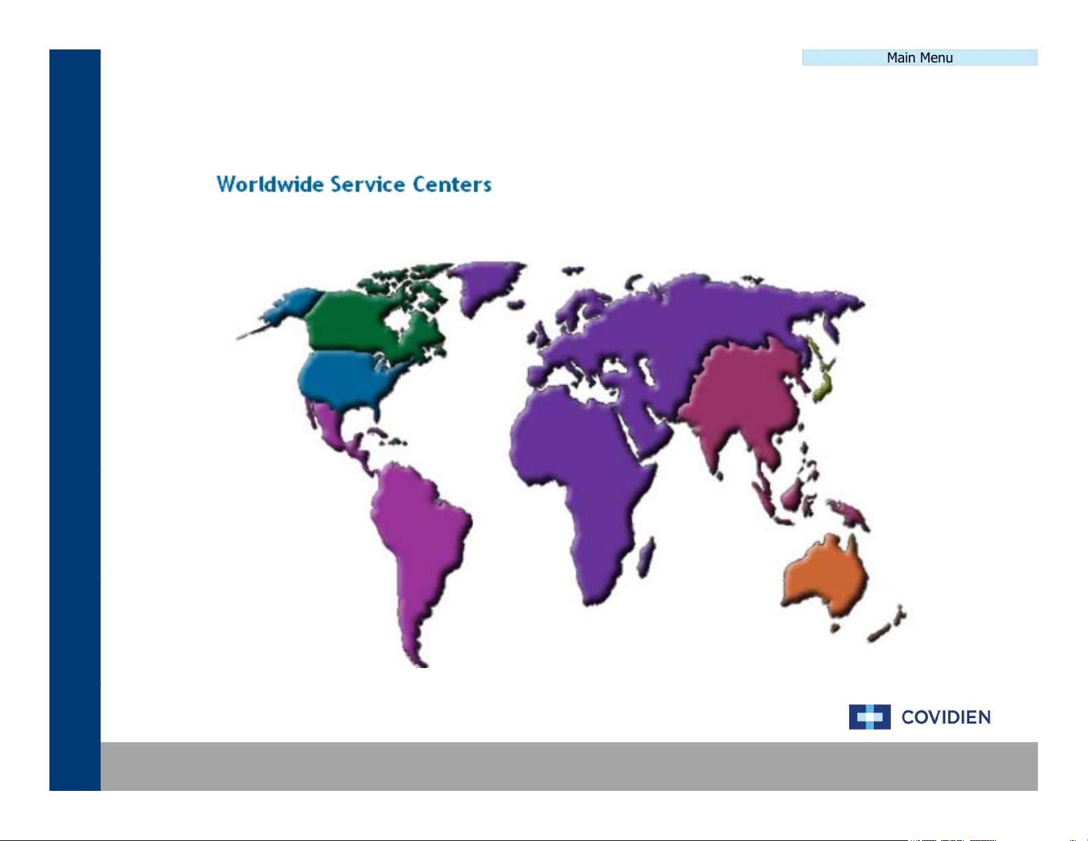
Click anywhere on the map to access the Covidien technical support websiteClick anywhere on the map to access the Covidien technical support website
Covidien | December 7, 2011 | Confidential
Main Menu
The
different
calibration
levels
defined
below
are
the
by
d
i
d
Calibration Level 0
Utility Calibration
Main Menu
Calibration ProcedureCalibration Procedure
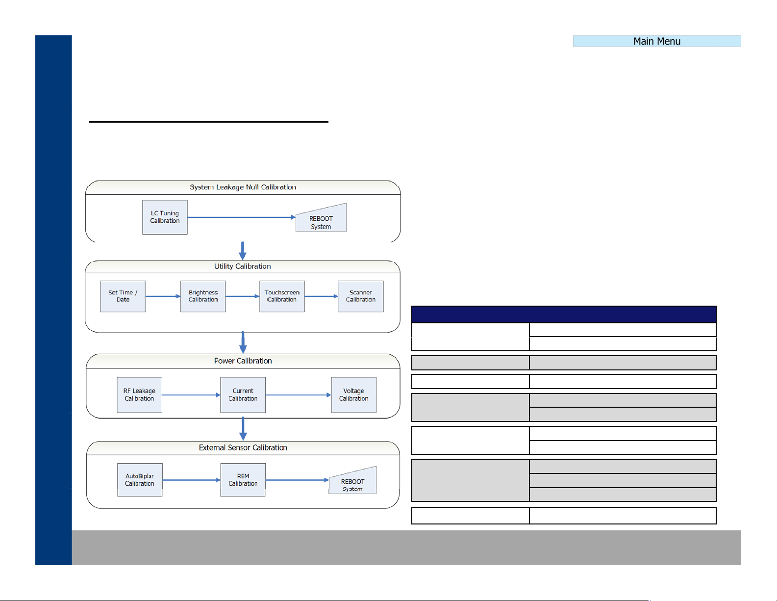
CALIBRATION PROCEDURE DEFINITION
The calibration procedure has been broken down into four different areas of calibration. The different calibration areas
segregate the full calibration procedure into smaller, more manageable calibration sections. These sections are then
selected based on the service performed. Additional information can be found by clicking on the flow chart below.
MINIMUM requirement of level of calibration to be
performed. Ultimately, a full, level 6 calibration is
preferred for all levels of service work completed.
The full calibration procedure definition, including a step-
-step procedure, canbefoun
Service Manual. The information found in the Calibration
Procedure section of this guide is for reference only.
CalibrationLevelDefinition
No calibration required
Periodic Safety Check required
ntheForceTria
Covidien | December 7, 2011 | Confidential
Calibration Level 1 Scanner Calibration
Calibration Level 2 System Leakage Null Calibration
Calibration Level 3
Calibration Level 4
Calibration Level 5
Calibration Level 6 Full calibration required
System Leakage Null Calibration
Power Calibration
System Leakage Null Calibration
Power Calibration
External Sensor Calibration
System Leakage Null Calibration
Main Menu
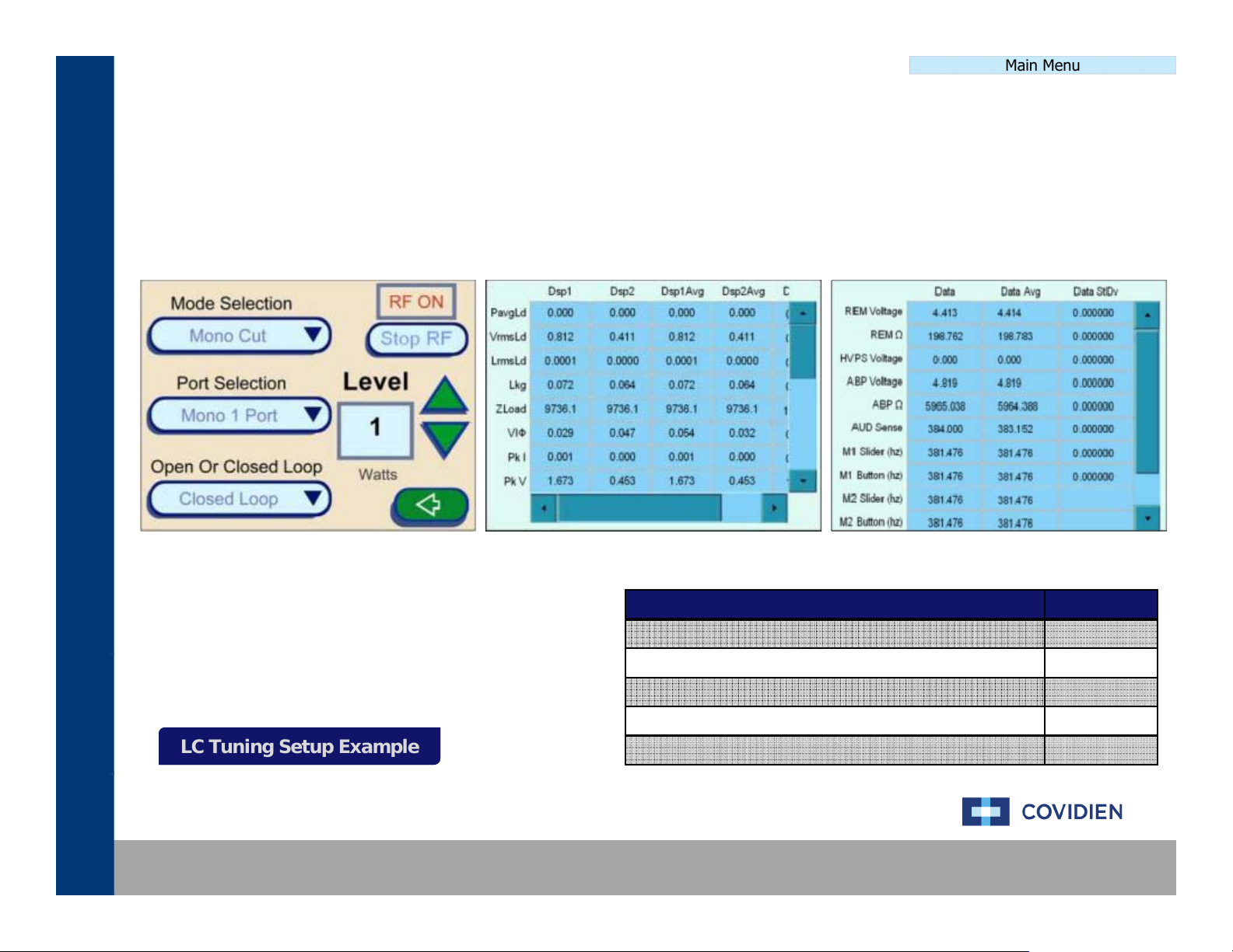
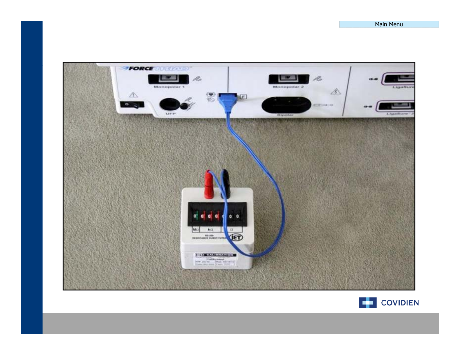
The
System
Leakage
Null
Calibration
process
consists
of
adjusting
theLCTuning
on
the
system
This
is
Calibration Procedure
LC Tuning Setup Example
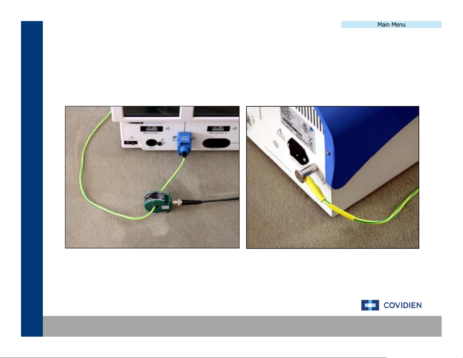
System Leakage Null CalibrationSystem Leakage Null Calibration
.
accomplished by using the equipment outlined below and using the touch screen menu navigating to the
calibration section.
Main Menu Service Diagnostics Debug Mode
LC Tuning Setup ExampleLC Tuning Setup Example
Covidien | December 7, 2011 | Confidential
Item Qty
Ground Lug Cable 1
D4 Cable with Current Probe 1
Current Monitor 1
REM Adaptor 1
#0 Flathead Screwdriver 1
LC Tuning Calibration SetupLC Tuning Calibration Setup
System Leakge Null Cal
Main Menu
Covidien | December 7, 2011 | Confidential
Utility CalibrationUtility Calibration
The
Utility
Calibration
process
consists
of
setting
up
the
date
&
time
screen
brightness
touch
screen
and
p
Brightness Setup ExampleBrightness Setup Example
Calibration Procedure
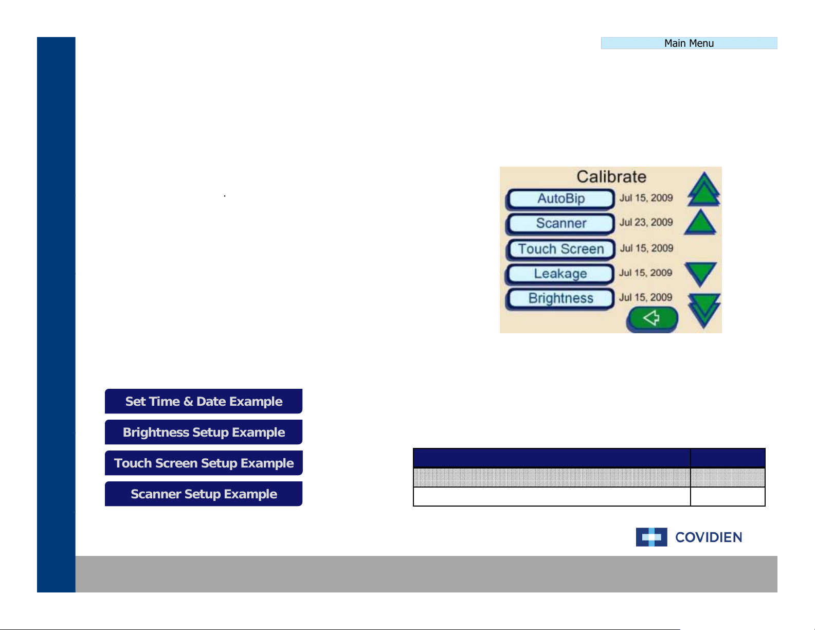
Set Time & Date Example
Brightness Setup Example
Touchscreen Setup Example
Scanner Setup Example
Main Menu
,
scanners on the system. This is accomplished by using the equipment outlined below and using the touch
screen menu navigating to the calibration section.
TIME & DATE:
Main Menu Setup TimeAnd Date
BRIGHTNESS, TOUCH SCREEN, & SCANNER:
Main Menu Service Maintenance Calibrate Brightness
Touch Screen
Scanner
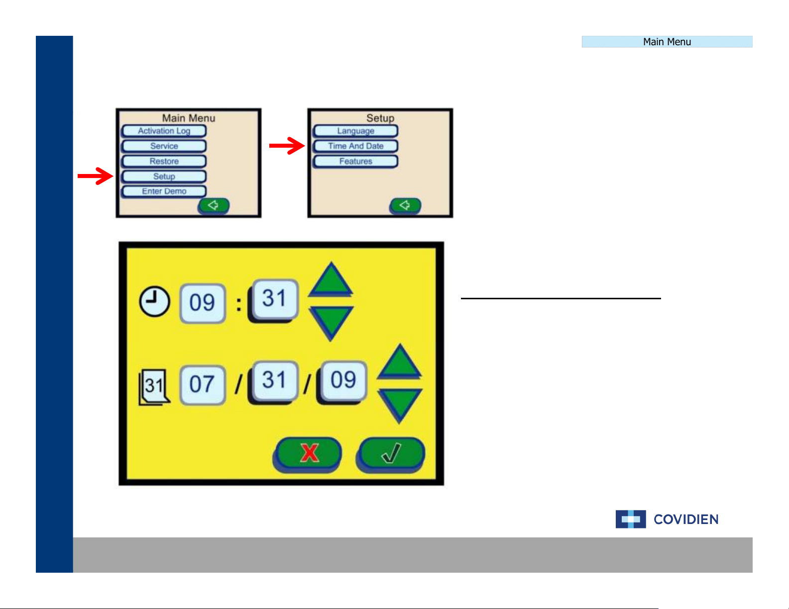
Set Time & Date ExampleSet Time & Date Example
,
,
Touch Screen Setup ExampleTouch Screen Setup Example
Scanner Setup ExampleScanner Setup Example
Covidien | December 7, 2011 | Confidential
Item Qty
Stylus (Optional) 1
Ligasure 1 Dot Code Instrument 1
Set Time & Date SetupSet Time & Date Setup
time
Utility Calibration
Main Menu
DATE & TIME SETUP PROCEDURE
Navigate the ForceTriad touch screen menu to
“Setup”, then “Time And Date” to the screen to the
left. On this screen, use thegreen up and down
arrows to set the date and time.
After completion of setting the date and time,
select the green check mark to store the date &
.
Covidien | December 7, 2011 | Confidential
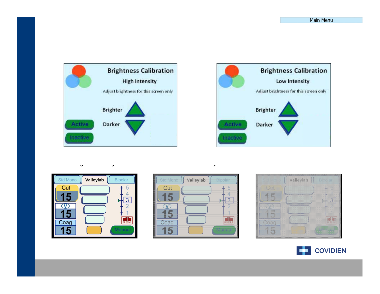
Brightness Calibration SetupBrightness Calibration Setup
High Intensity
Low Intensity
y
y
gy
y
Utility Calibration
Main Menu
Covidien | December 7, 2011 | Confidential
High Intensit
Low Intensit
Inactive Screen
Touch Screen Calibration SetupTouch Screen Calibration Setup
gpp
Utility Calibration
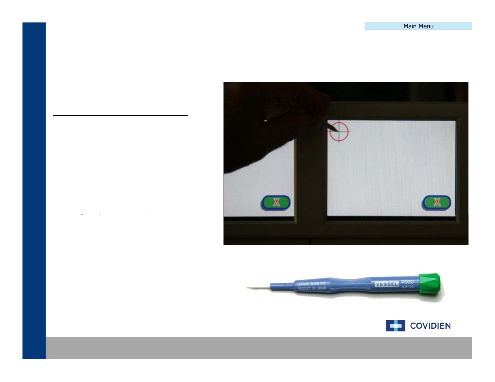
TOUCH SCREEN SETUP PROCEDURE
Under the “Calibration” section of the touch
screen menu, select the touch screen
calibration. You will be prompted to touch the
crosshair icon on the screen.
Preferably using a stylus, begin touching the
center mark of the crosshairs beginning with
the left screen moving right.
Main Menu
Your finger tip is an acceptable alternative to
the stylus.
Covidien | December 7, 2011 | Confidential
Scanner Calibration SetupScanner Calibration Setup
insert
dot
code
handsets
Utility Calibration
Scanner Calibration
Performing initial scanner calibration on all ports.
Please wait for calibration to complete.
Cancel may leave scanners in unusable state.
Main Menu
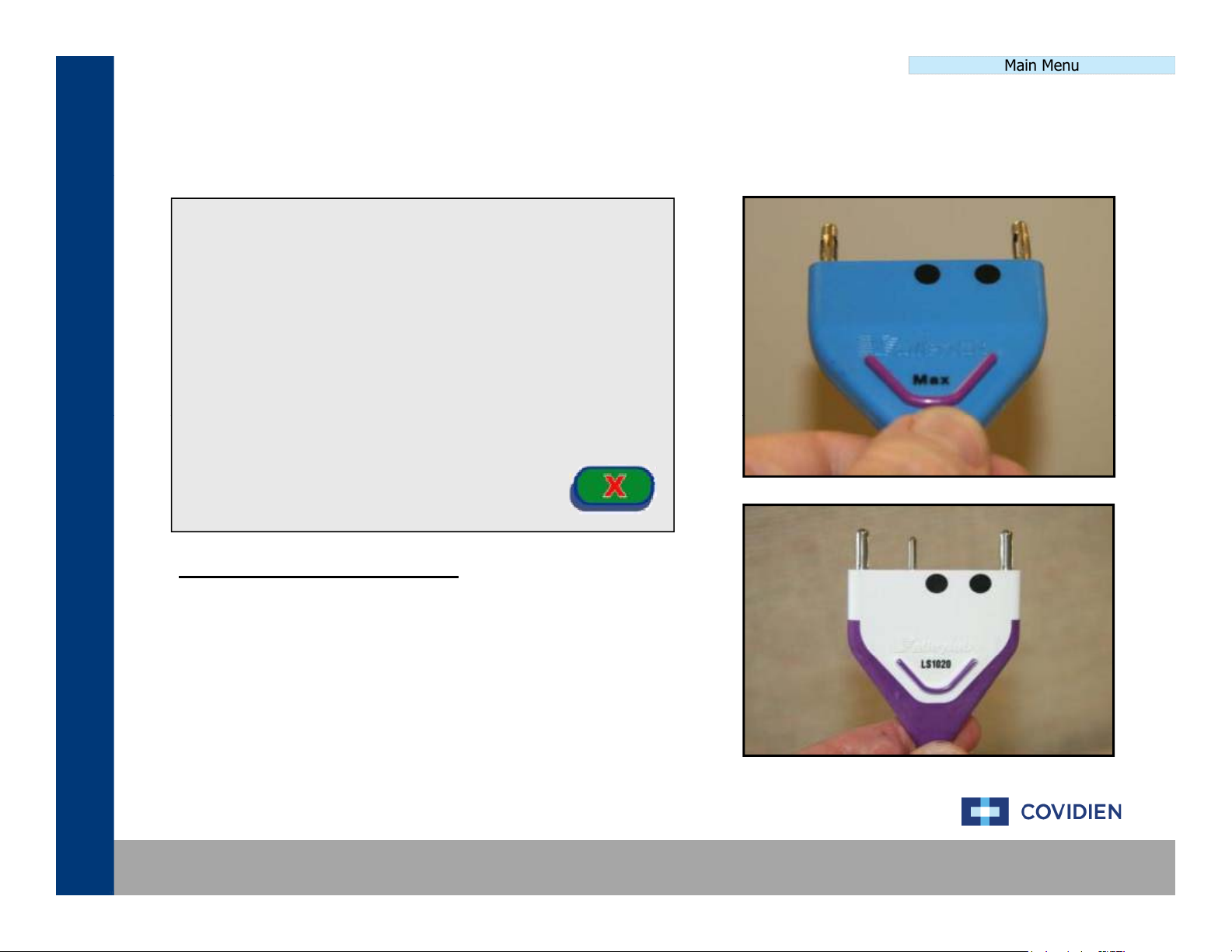
SCANNER SETUP PROCEDURE
Under the “Calibration” section of the touch screen menu,
select the scanner calibration. You will be prompted to
.
Using appropriate hand pieces, insert the hand piece into
the corresponding receptacles as prompted by the on
screen commands.
Covidien | December 7, 2011 | Confidential
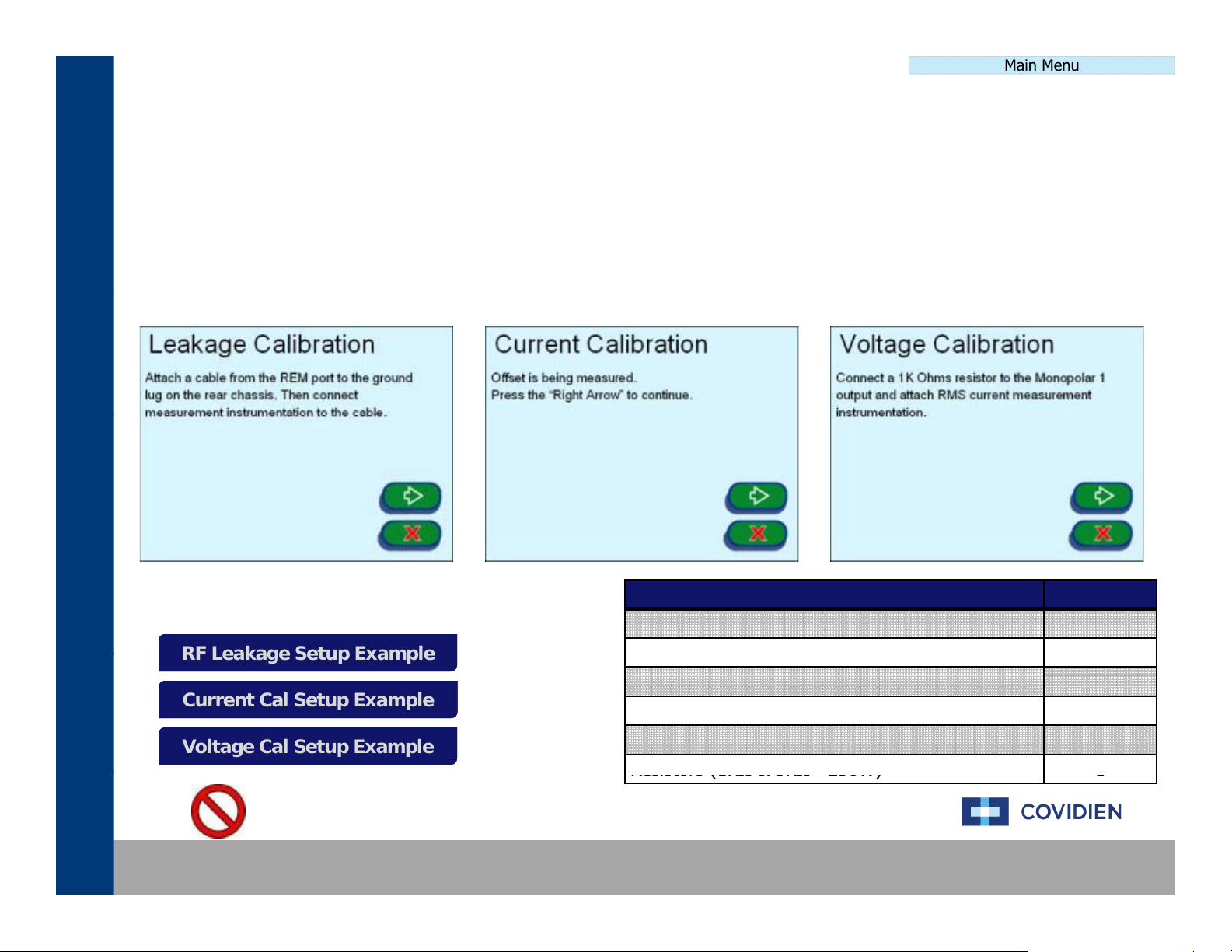
Power CalibrationPower Calibration
The
Power
Calibration
process
consists
of
measuring
theRFleakage
current
and
voltage
on
the
system
This
is
RF Leakage Setup ExampleRF Leakage Setup Example
D4 Cable with Current Probe
1
Resistors (1K
Ω
& 5K
Ω
250W)
1
Calibration Procedure
RF Leakage Setup Example
Current Cal Setup Example
Voltage Cal Setup Example
Main Menu
,
accomplished by using the equipment outlined below and using the touch screen menu navigating to the
calibration section.
Main Menu Service Maintenance Calibrate Leakage
Current Cal
Voltage Cal
Item Qty
Ground Lug Cable 1
,
.
Current Cal Setup ExampleCurrent Cal Setup Example
Voltage Cal Setup ExampleVoltage Cal Setup Example
Covidien | December 7, 2011 | Confidential
Current Monitor 1
REM Adaptor 1
Cable Lead 2
-
WARNING: Do not hold down on the pushbuttons!
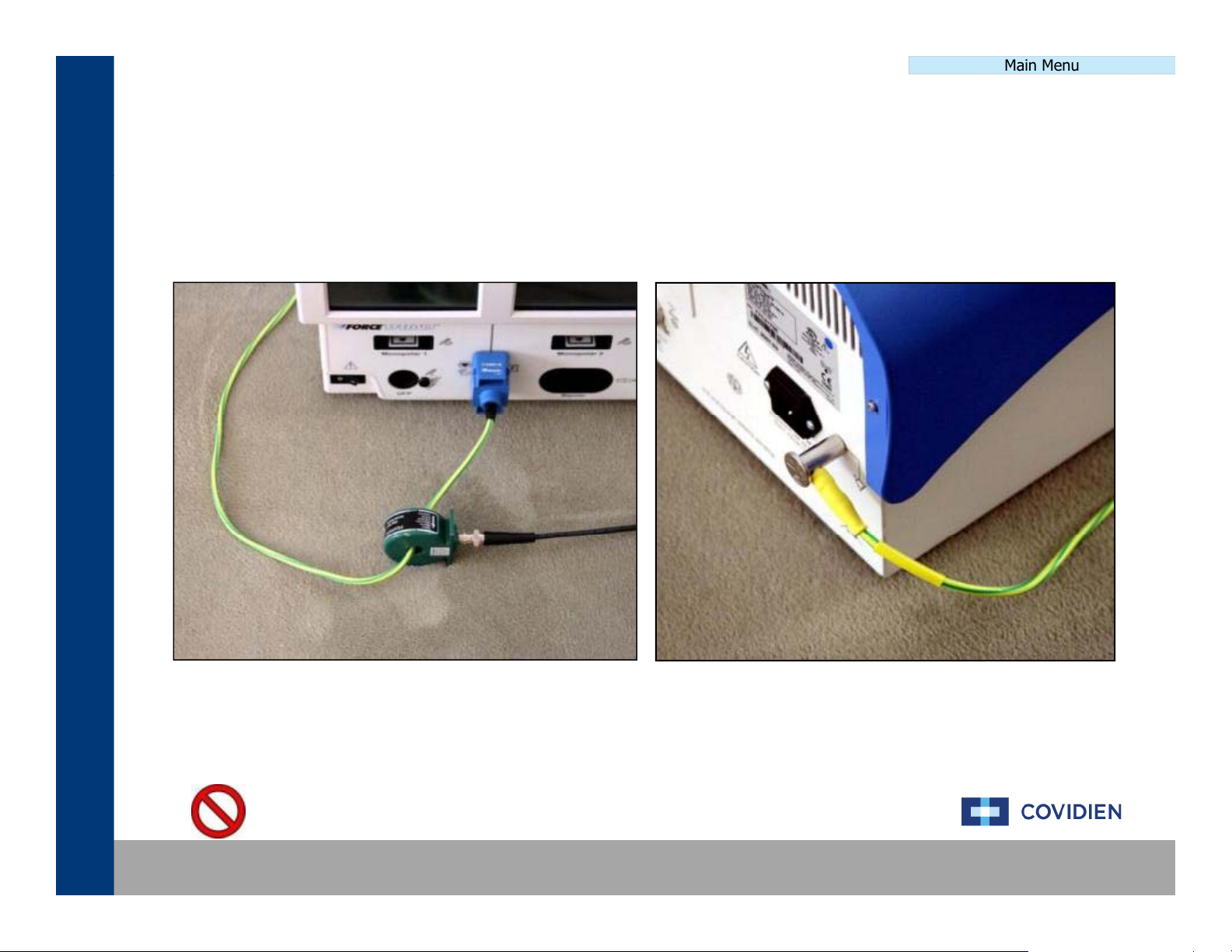
RF Leakage Calibration SetupRF Leakage Calibration Setup
Power Calibration
Main Menu
Covidien | December 7, 2011 | Confidential
WARNING: Do not hold down on the pushbuttons!
Current Calibration SetupCurrent Calibration Setup
Power Calibration
Main Menu
Covidien | December 7, 2011 | Confidential
WARNING: Do not hold down on the pushbuttons!
Voltage Calibration SetupVoltage Calibration Setup
Power Calibration
Main Menu
Covidien | December 7, 2011 | Confidential
WARNING: Do not hold down on the pushbuttons!
Main Menu
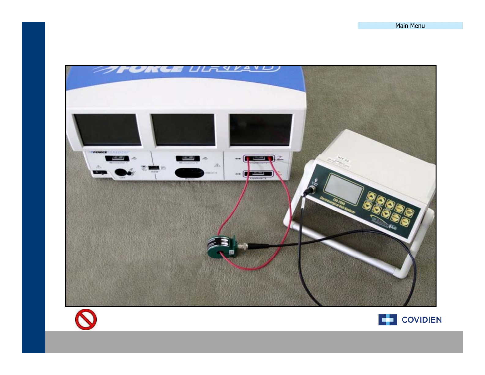
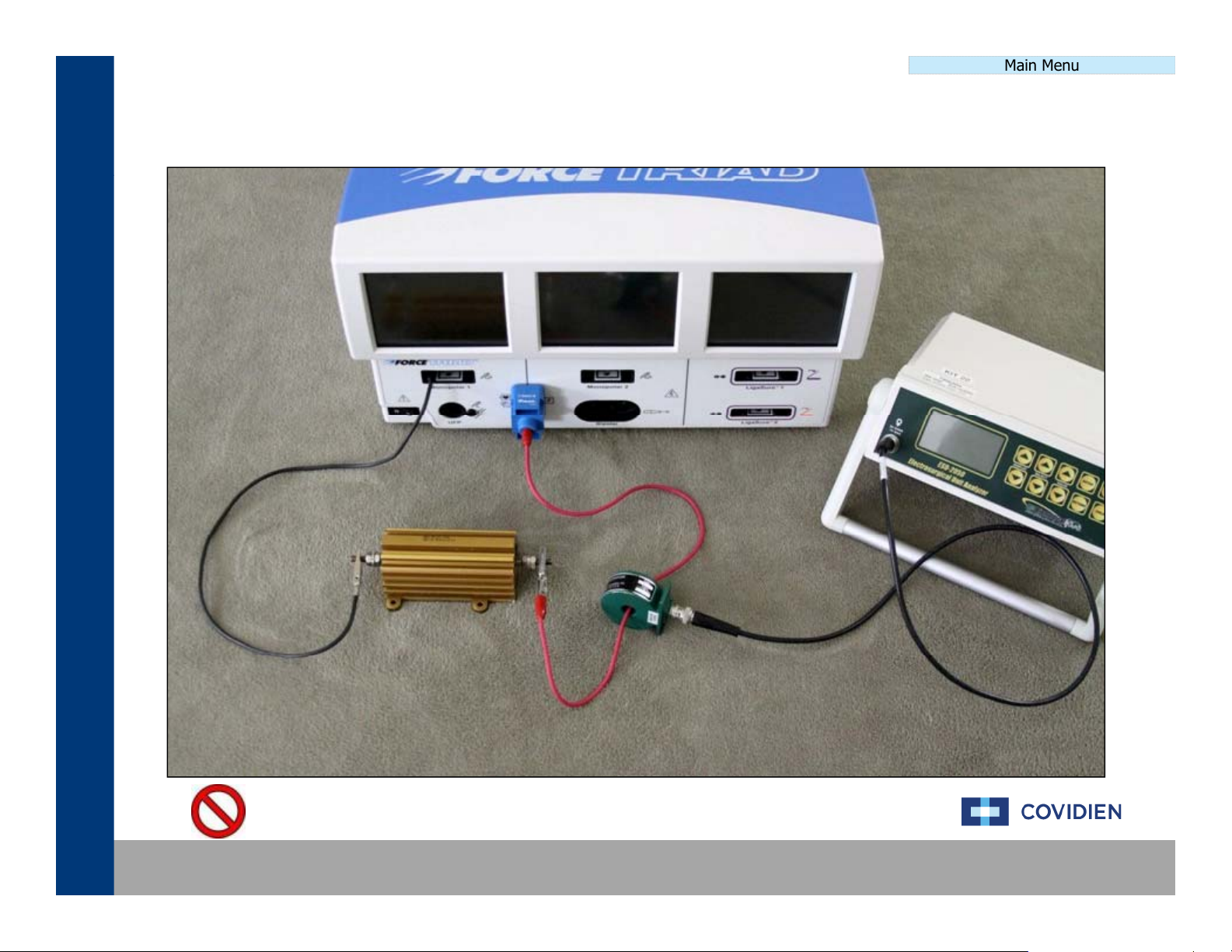
The
External
Sensor
Calibration
process
consists
of
measuring
the
REM
and
AutoBipolar
settings
on
the
system
p
p
Calibration Procedure
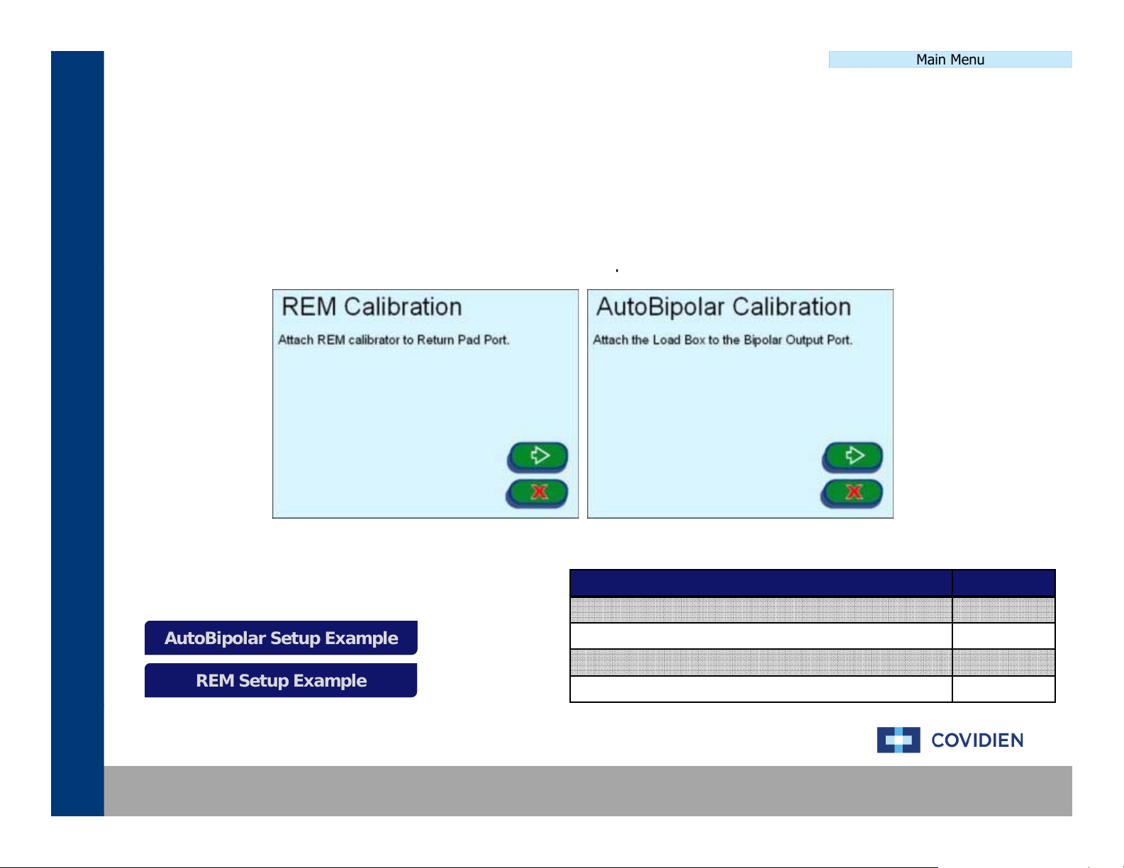
Autobipolar Setup Example
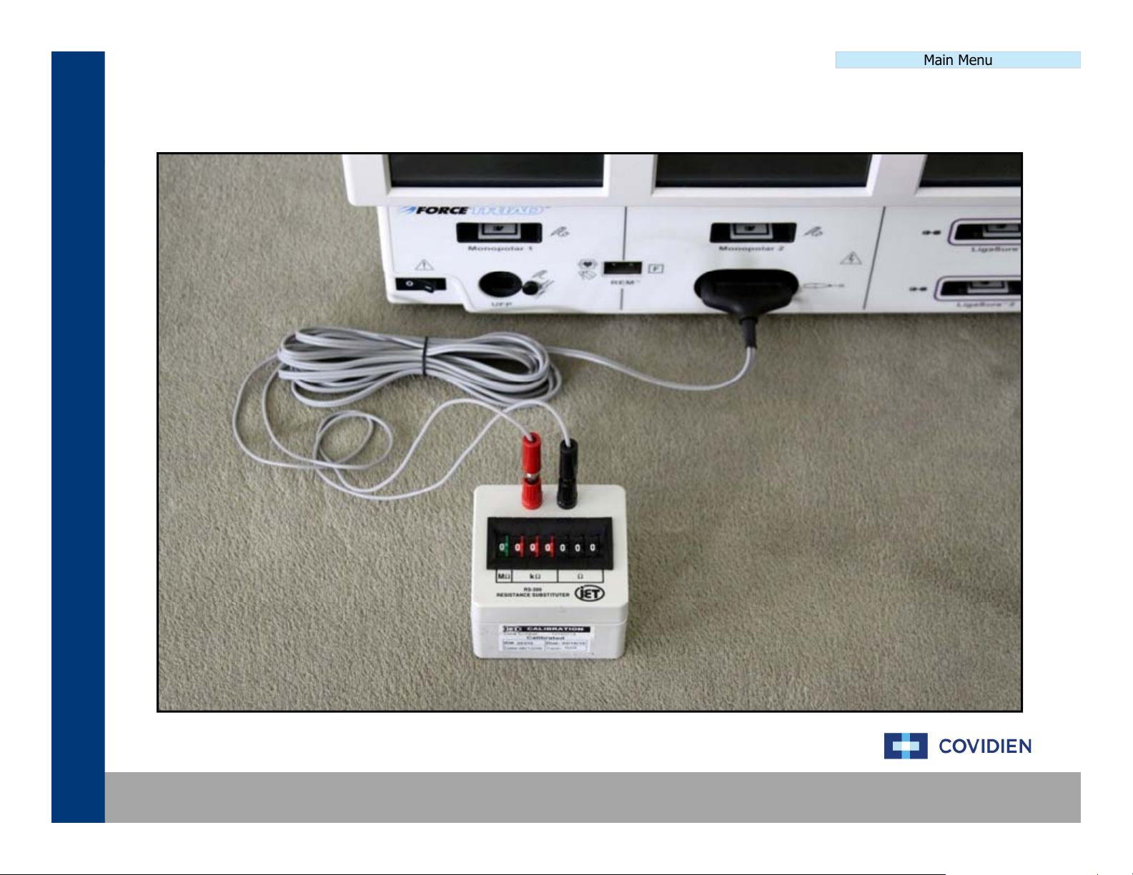
REM Setup Example
External Sensor CalibrationExternal Sensor Calibration
This is accomplished by using the equipment outlined below and using the touch screen menu navigating to the
calibration section.
Main Menu Service Maintenance Calibrate REM
AutoBi
.
AutoBipolar Setup ExampleAutoBipolar Setup Example
REM Setup ExampleREM Setup Example
Covidien | December 7, 2011 | Confidential
Item Qty
REM Calibrator 1
Load Box 1
REM Calibration Cable 1
AutoBipolar Cable 1
Autobipolar Calibration SetupAutobipolar Calibration Setup
External Sensor Calibration
Main Menu
Covidien | December 7, 2011 | Confidential
REM Calibration SetupREM Calibration Setup
External Sensor Calibration
Main Menu
Covidien | December 7, 2011 | Confidential
Main Menu
E3E3
E12E12
E21E21
E259E259
E268E268
E277E277
E286E286
E295E295
E304E304
E5E5
E14E14
E23E23
E261E261
E270E270
E279E279
E288E288
E297E297
E306E306
E7E7
E16E16
E25E25
E263E263
E272E272
E281E281
E290E290
E299E299
E308E308
E9E9
E18E18
E27E27
E265E265
E274E274
E283E283
E292E292
E301E301
E310E310
Main Menu
E2
E11
E20
E258
E267
E276
E285
E294
E303
E3
E12
E21
E259
E268
E277
E286
E295
E304
E4
E13
E22
E260
E269
E278
E287
E296
E305
E5
E14
E23
E261
E270
E279
E288
E297
E6
E15
E24
E262
E271
E280
E289
E298
E306
E307
E7
E16
E25
E263
E272
E281
E290
E299
E8
E17
E26
E264
E273
E282
E291
E300
E308
E309
E9
E18
E27
E265
E274
E283
E292
E301
E310
E10
E19
E257
E266
E275
E284
E293
E302
E311
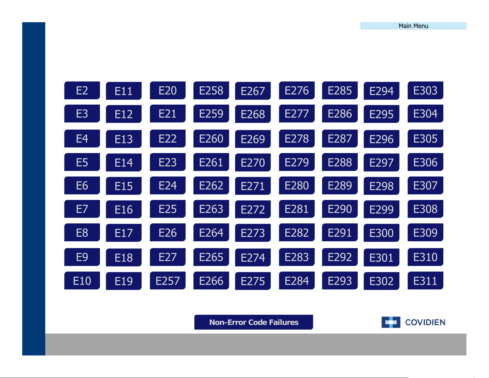
Non-Error Code Failures
Error Code Definition & TroubleshootingError Code Definition & Troubleshooting
E2E2
E4E4
E6E6
E8E8
E11E11
E13E13
E15E15
E17E17
E20E20
E22E22
E24E24
E26E26
E258E258
E260E260
E262E262
E264E264
E267E267
E269E269
E271E271
E273E273
E276E276
E278E278
E280E280
E282E282
E285E285
E287E287
E289E289
E291E291
E294E294
E296E296
E298E298
E300E300
E303E303
E305E305
E307E307
E309E309
E10E10
Covidien | December 7, 2011 | Confidential
E19E19
E257E257
E266E266
Non-Error Code FailuresNon-Error Code Failures
E275E275
E284E284
E293E293
E302E302
E311E311
NonNon--Error Code TroubleshootingError Code Troubleshooting
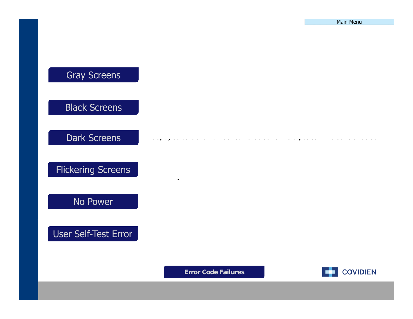
The system responds to a power cycle and begins the system initiation
The three
Dark ScreensDark Screens
display screens show a much darker screen of the expected white Covidien screen.
y
Main Menu
Gray Screens
Black Screens
Dark Screens
Flickering Screens
No Power
User Self-Test Error
Error Code Failures
The system responds to a power cycle and begins the system initiation. The three
Gray ScreensGray Screens
display screens show a blank, gray screen instead of displaying the white Covidien
screen.
Main Menu
Black ScreensBlack Screens
Flickering ScreensFlickering Screens
No PowerNo Power
User Self-Test ErrorUser Self-Test Error
.
display screens show a blank, black screen instead of displaying the white Covidien
screen.
The system responds to a power cycle and begins the system initiation. The three
This can range from slightly darker to nearly unreadable.
The system responds to a power cycle and begins the system initiation. The
screen and/or screens begin to flicker. The flickering can happen once or occur
constantly.
The system does not respond to a power cycle. The system displays and scanners
do not illuminate.
The system initiates the self-test and may pass a portion of the testing. The unit
then fails at some point during the self-test. The unit will generate an error but not
an error code.
Error Code FailuresError Code Failures
Covidien | December 7, 2011 | Confidential

NonNon--Error Code Failures Error Code Failures -- Gray ScreensGray Screens
T
LEADING
COMPONENT
REPLACEMENTS
1.P
Non-Error Code Menu
he failures that aregenerated where the
displays are blank and gray, there are a couple
of scenarios that could cause this. Typically,
cables that are not connected or fully
connected are the cause.
NON-COMPONENT ACTIONS
1. Power cycling the system
2. Inspecting the component cables
1. Ethernet Cable
• (Cable between Controller and Display)
2. Steering Relay Cable
• (Cable between SR and Display)
Main Menu
NON-COMPONENT ACTIONS INSTRUCTION
ower Cycle the unit and allow the system to perform the self-test.
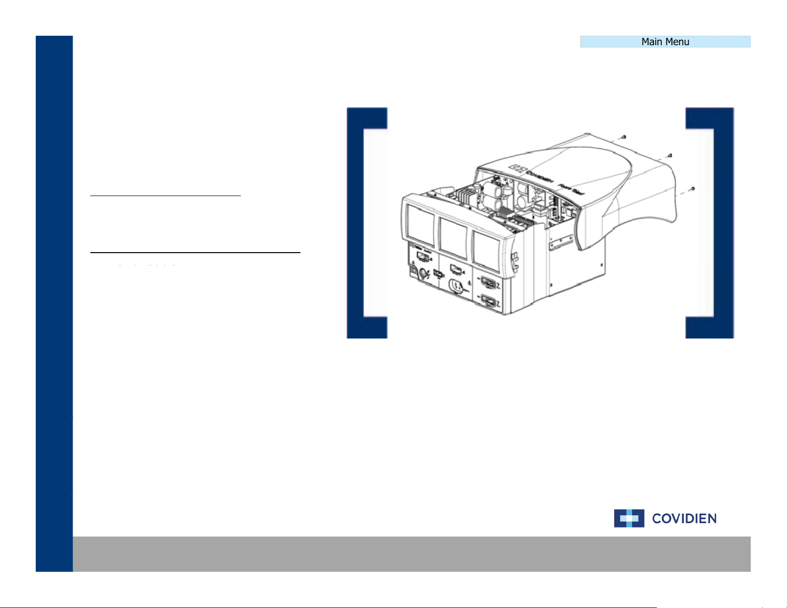
2. Remove the cover to the ForceTriad system and inspect the system
boards ensuring that the boards are properly seated within the
unit and that all cables are also securely connected.
Covidien | December 7, 2011 | Confidential

NonNon--Error Code Failures Error Code Failures -- Black ScreensBlack Screens
T
NON
COMPONENT
ACTIONS
1.
Inverter
Board
1.P
Non-Error Code Menu
he failures that aregenerated where the
displays are blank and black, there is typically
one cause of this type of failure, the inverter
board.
-
1. Power cycling the system
2. Inspecting the component cables
LEADING COMPONENT REPLACEMENTS
Main Menu
NON-COMPONENT ACTIONS INSTRUCTION
ower Cycle the unit and allow the system to perform the self-test.
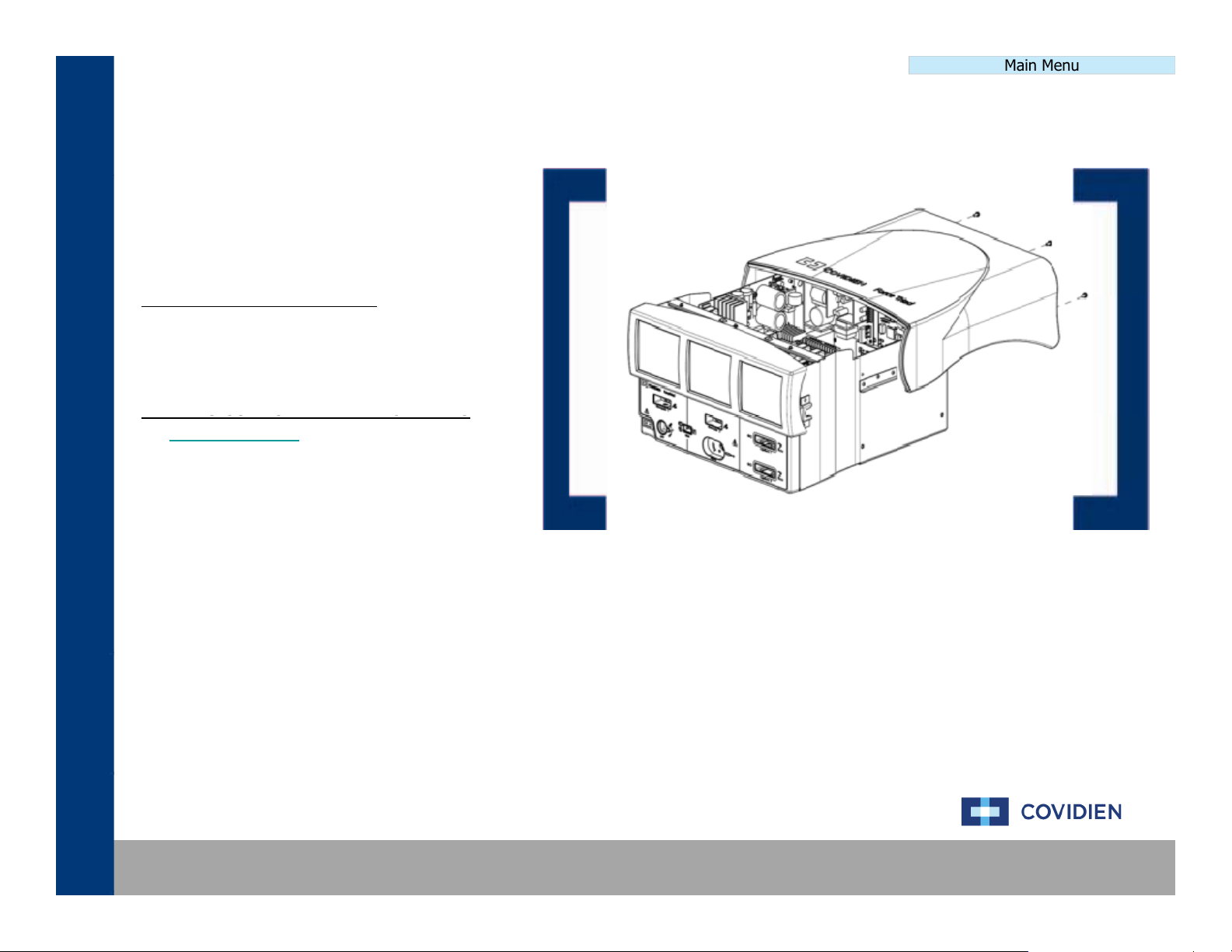
2. Remove the cover to the ForceTriad system and inspect the system
boards ensuring that the boards are properly seated within the
unit and that all cables are also securely connected.
Covidien | December 7, 2011 | Confidential

NonNon--Error Code Failures Error Code Failures ––No PowerNo Power
T
LEADING
COMPONENT
REPLACEMENTS
1.P
Non-Error Code Menu
he failures that aregenerated where the
system does not power on nor is there any
indication that the system received a signal to
power on. There are a couple of possibilities
to cause this type of failure.
NON-COMPONENT ACTIONS
1. Power cycling the system
2. Inspecting the component cables
1. System Fuse
2. Power Cable
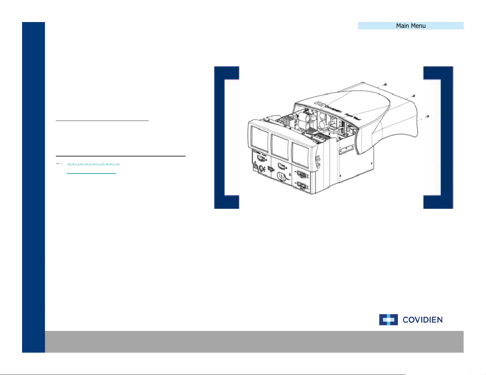
3. Controller Board
4. Low Voltage Power Supply
Main Menu
NON-COMPONENT ACTIONS INSTRUCTION
ower Cycle the unit and allow the system to perform the self-test.
2. Remove the cover to the ForceTriad system and inspect the system
boards ensuring that the boards are properly seated within the
unit and that all cables are also securely connected.
Covidien | December 7, 2011 | Confidential
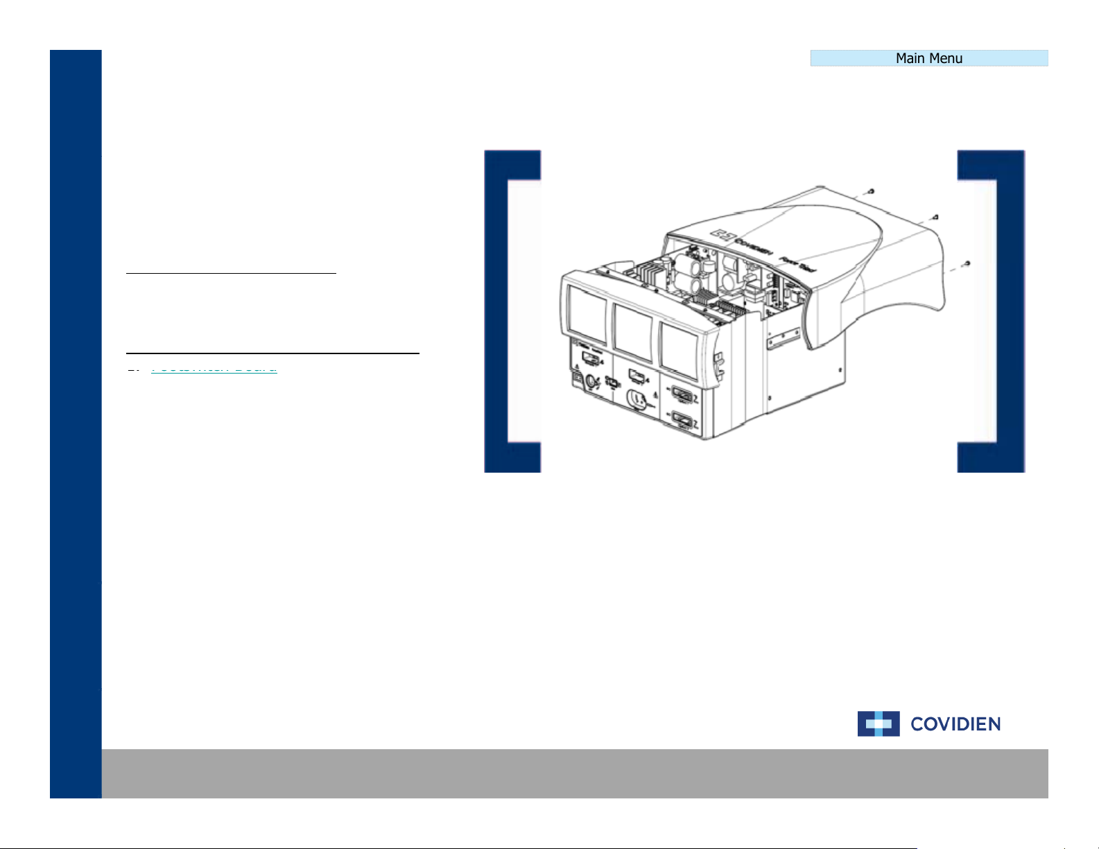
NonNon--Error Code Failures Error Code Failures ––User SelfUser Self--TestTest
T
NON
COMPONENT
ACTIONS
1.
Footswitch
Board
1.P
Non-Error Code Menu
he failure that isgenerated where the system
fails a user generated self-test via the
“Diagnostics” menu the typical failure mode is
the Footswitch Board.
-
1. Power cycling the system
2. Inspecting the component cables
LEADING COMPONENT REPLACEMENTS
Main Menu
NON-COMPONENT ACTIONS INSTRUCTION
ower Cycle the unit and allow the system to perform the self-test.
2. Remove the cover to the ForceTriad system and inspect the system
boards ensuring that the boards are properly seated within the
unit and that all cables are also securely connected.
Covidien | December 7, 2011 | Confidential
Main Menu
T
NON
COMPONENT
ACTIONS
er
Cable
oe
Cab e
1.P
Non-Error Code Menu
NonNon--Error Code Failures Error Code Failures –– Flickering ScreensFlickering Screens
he failure that isgenerated where the system
fails a user generated self-test via the
“Diagnostics” menu the typical failure mode is
the Footswitch Board.
-
1. Power cycling the system
2. Inspecting the component cables
LEADING COMPONENT REPLACEMENTS
1. Pow
• (Cable between SR and Display)
NON-COMPONENT ACTIONS INSTRUCTION
ower Cycle the unit and allow the system to perform the self-test.
2. Remove the cover to the ForceTriad system and inspect the system
boards ensuring that the boards are properly seated within the
unit and that all cables are also securely connected.
Covidien | December 7, 2011 | Confidential
NonNon--Error Code Failures Error Code Failures –– Dark ScreensDark Screens
T
NON
COMPONENT
ACTIONS
G
COMPO
S
G
CO O
CS
1.P
Non-Error Code Menu
he failure that isgenerated where the system
fails a user generated self-test via the
“Diagnostics” menu the typical failure mode is
the Footswitch Board.
-
1. Power cycling the system
2. Inspecting the component cables
3. Brightness calibration
Main Menu
LEADIN
1. Display Inverter
NENT REPLACEMENT
NON-COMPONENT ACTIONS INSTRUCTION
ower Cycle the unit and allow the system to perform the self-test.
2. Remove the cover to the ForceTriad system and inspect the system
boards ensuring that the boards are properly seated within the
unit and that all cables are also securely connected.
3. Perform a brightness calibration as outlined in the Service Manual.
Covidien | December 7, 2011 | Confidential

E2 E2 –– ERR_SE_ICL_ERRORERR_SE_ICL_ERROR
T
1.Power
cycling
the
system
1.P
Error Code Definition Menu
he E2 error code is designated and issued to
signify that the unit is unable to communicate
to the hardware using the HOST ICL registers.
NON-COMPONENT ACTIONS
2. Performing a full recalibration
LEADING COMPONENT REPLACEMENTS
1. Controller Board
Main Menu
NON-COMPONENT ACTIONS INSTRUCTION
ower Cycle the unit and allow the system to perform the self-test.
2. Remove the cover to the ForceTriad system and inspect the system
boards ensuring that the boards are properly seated within the
unit and that all cables are also securely connected.
3. Perform a level 6 calibration as outlined in the Calibration Section.
Covidien | December 7, 2011 | Confidential

E3 E3 –– ERR_SE_APP_ROM_FAILERR_SE_APP_ROM_FAIL
T
1.Power
cycling
the
system
1.P
Error Code Definition Menu
he E3 error code is designated and issued to
signify that the DSP application ROM check
failed during start-up.
NON-COMPONENT ACTIONS
2. Performing a full recalibration
LEADING COMPONENT REPLACEMENTS
1. Controller Board
Main Menu
NON-COMPONENT ACTIONS INSTRUCTION
ower Cycle the unit and allow the system to perform the self-test.
2. Remove the cover to the ForceTriad system and inspect the system
boards ensuring that the boards are properly seated within the
unit and that all cables are also securely connected.
3. Perform a level 6 calibration as outlined in the Calibration Section.
Covidien | December 7, 2011 | Confidential

E4 E4 –– ERR_SE_BOOT_ROM_FAILERR_SE_BOOT_ROM_FAIL
T
1.Power
cycling
the
system
1.P
Error Code Definition Menu
he E4 error code is designated and issued to
signify that the DSP boot ROM check failed
during start-up.
NON-COMPONENT ACTIONS
2. Performing a full recalibration
LEADING COMPONENT REPLACEMENTS
1. Controller Board
Main Menu
NON-COMPONENT ACTIONS INSTRUCTION
ower Cycle the unit and allow the system to perform the self-test.
2. Remove the cover to the ForceTriad system and inspect the system
boards ensuring that the boards are properly seated within the
unit and that all cables are also securely connected.
3. Perform a level 6 calibration as outlined in the Calibration Section.
Covidien | December 7, 2011 | Confidential

E5 E5 -- ERR_SE_RAM_FAILERR_SE_RAM_FAIL
T
1.Power
cycling
the
system
1.P
Error Code Definition Menu
he E5 error code is designated and issued to
signify that the DSP RAM check failed during
start-up.
NON-COMPONENT ACTIONS
2. Performing a full recalibration
LEADING COMPONENT REPLACEMENTS
1. Controller Board
Main Menu
NON-COMPONENT ACTIONS INSTRUCTION
ower Cycle the unit and allow the system to perform the self-test.
2. Remove the cover to the ForceTriad system and inspect the system
boards ensuring that the boards are properly seated within the
unit and that all cables are also securely connected.
3. Perform a level 6 calibration as outlined in the Calibration Section.
Covidien | December 7, 2011 | Confidential
E6 E6 –– ERR_SE_RTOS_FAILERR_SE_RTOS_FAIL
T
NON
COMPONENT
ACTIONS
1.
Controller
Board
1.P
Error Code Definition Menu
he E6 error code is designated and issued to
signify that a software error has occurred.
The E6 error code is typically issued during
real time to signify an operating system error.
-
1. Power cycling the system
2. Performing a full recalibration
LEADING COMPONENT REPLACEMENTS
2. System Display
Main Menu
NON-COMPONENT ACTIONS INSTRUCTION
ower Cycle the unit and allow the system to perform the self-test.
2. Remove the cover to the ForceTriad system and inspect the system
boards ensuring that the boards are properly seated within the
unit and that all cables are also securely connected.
3. Perform a level 6 calibration as outlined in the Calibration Section.
Covidien | December 7, 2011 | Confidential

E7 E7 –– ERR_SE_GEN_FAILERR_SE_GEN_FAIL
T
1.Power
cycling
the
system
1.P
Error Code Definition Menu
he E7 error code is designated and issued to
signify that the generator has developed a
general system error.
NON-COMPONENT ACTIONS
2. Performing a full recalibration
LEADING COMPONENT REPLACEMENTS
1. Controller Board
Main Menu
NON-COMPONENT ACTIONS INSTRUCTION
ower Cycle the unit and allow the system to perform the self-test.
2. Remove the cover to the ForceTriad system and inspect the system
boards ensuring that the boards are properly seated within the
unit and that all cables are also securely connected.
3. Perform a level 6 calibration as outlined in the Calibration Section.
Covidien | December 7, 2011 | Confidential

E8 E8 -- ERR_SE_CRITICAL_DATAERR_SE_CRITICAL_DATA
T
1.Power
cycling
the
system
1.P
Error Code Definition Menu
he E8 error code is designated and issued to
signify that the system has a software error
caused by a corrupt data string.
NON-COMPONENT ACTIONS
2. Performing a full recalibration
LEADING COMPONENT REPLACEMENTS
1. Controller Board
Main Menu
NON-COMPONENT ACTIONS INSTRUCTION
ower Cycle the unit and allow the system to perform the self-test.
2. Remove the cover to the ForceTriad system and inspect the system
boards ensuring that the boards are properly seated within the
unit and that all cables are also securely connected.
3. Perform a level 6 calibration as outlined in the Calibration Section.
Covidien | December 7, 2011 | Confidential

E9 E9 -- ERR_SE_ASSERTERR_SE_ASSERT
T
NON
COMPONENT
ACTIONS
Controller
d
Co t o e
oa d
1.P
Error Code Definition Menu
he E9 error code is designated and issued to
signify that the system has developed a
software error that has generated an
assertion.
-
1. Power cycling the system
2. Performing a full recalibration
LEADING COMPONENT REPLACEMENTS
1.
Boar
Main Menu
NON-COMPONENT ACTIONS INSTRUCTION
ower Cycle the unit and allow the system to perform the self-test.
2. Remove the cover to the ForceTriad system and inspect the system
boards ensuring that the boards are properly seated within the
unit and that all cables are also securely connected.
3. Perform a level 6 calibration as outlined in the Calibration Section.
Covidien | December 7, 2011 | Confidential

E10 E10 -- ERR_SE_INVALID_DATAERR_SE_INVALID_DATA
T
1.Power
cycling
the
system
1.P
Error Code Definition Menu
he E10 error code is designated and issued
to signify that a software failure occurred
because of an invalid data string.
NON-COMPONENT ACTIONS
2. Performing a full recalibration
LEADING COMPONENT REPLACEMENTS
1. Controller Board
Main Menu
NON-COMPONENT ACTIONS INSTRUCTION
ower Cycle the unit and allow the system to perform the self-test.
2. Remove the cover to the ForceTriad system and inspect the system
boards ensuring that the boards are properly seated within the
unit and that all cables are also securely connected.
3. Perform a level 6 calibration as outlined in the Calibration Section.
Covidien | December 7, 2011 | Confidential

Main Menu
T
1.Power
cycling
the
system
1.P
Error Code Definition Menu
E11 E11 -- ERR_SE_MACHINE_CHECK_EXCEPTIONERR_SE_MACHINE_CHECK_EXCEPTION
he E11 error code is designated and issued
to signify that a HOST processor machine
check exception has occurred.
NON-COMPONENT ACTIONS
2. Performing a full recalibration
LEADING COMPONENT REPLACEMENTS
1. Controller Board
NON-COMPONENT ACTIONS INSTRUCTION
ower Cycle the unit and allow the system to perform the self-test.
2. Remove the cover to the ForceTriad system and inspect the system
boards ensuring that the boards are properly seated within the
unit and that all cables are also securely connected.
3. Perform a level 6 calibration as outlined in the Calibration Section.
Covidien | December 7, 2011 | Confidential

Main Menu
T
1.Power
cycling
the
system
1.P
Error Code Definition Menu
E12 E12 -- ERR_SE_DATA_STORAGE_EXCEPTIONERR_SE_DATA_STORAGE_EXCEPTION
he E12 error code is designated and issued
to signify that a HOST processor data storage
exception has occurred.
NON-COMPONENT ACTIONS
2. Performing a full recalibration
LEADING COMPONENT REPLACEMENTS
1. Controller Board
NON-COMPONENT ACTIONS INSTRUCTION
ower Cycle the unit and allow the system to perform the self-test.
2. Remove the cover to the ForceTriad system and inspect the system
boards ensuring that the boards are properly seated within the
unit and that all cables are also securely connected.
3. Perform a level 6 calibration as outlined in the Calibration Section.
Covidien | December 7, 2011 | Confidential

E13 E13 -- ERR_SE_ISI_EXCEPTIONERR_SE_ISI_EXCEPTION
T
1.Power
cycling
the
system
1.P
Error Code Definition Menu
he E13 error code is designated and issued
to signify that a HOST processor data storage
exception has occurred.
NON-COMPONENT ACTIONS
2. Performing a full recalibration
LEADING COMPONENT REPLACEMENTS
1. Controller Board
Main Menu
NON-COMPONENT ACTIONS INSTRUCTION
ower Cycle the unit and allow the system to perform the self-test.
2. Remove the cover to the ForceTriad system and inspect the system
boards ensuring that the boards are properly seated within the
unit and that all cables are also securely connected.
3. Perform a level 6 calibration as outlined in the Calibration Section.
Covidien | December 7, 2011 | Confidential

E14 E14 -- ERR_SE_ALIGNMENT_EXCEPTIONERR_SE_ALIGNMENT_EXCEPTION
T
1.Power
cycling
the
system
1.P
Error Code Definition Menu
he E14 error code is designated and issued
to signify that a HOST processor alignment
exception has occurred.
NON-COMPONENT ACTIONS
2. Performing a full recalibration
LEADING COMPONENT REPLACEMENTS
1. Controller Board
Main Menu
NON-COMPONENT ACTIONS INSTRUCTION
ower Cycle the unit and allow the system to perform the self-test.
2. Remove the cover to the ForceTriad system and inspect the system
boards ensuring that the boards are properly seated within the
unit and that all cables are also securely connected.
3. Perform a level 6 calibration as outlined in the Calibration Section.
Covidien | December 7, 2011 | Confidential

E15 E15 -- ERR_SE_PROGRAM_EXCEPTIONERR_SE_PROGRAM_EXCEPTION
T
1.Power
cycling
the
system
1.P
Error Code Definition Menu
he E15 error code is designated and issued
to signify that a HOST processor program
exception has occurred.
NON-COMPONENT ACTIONS
2. Performing a full recalibration
LEADING COMPONENT REPLACEMENTS
1. Controller Board
Main Menu
NON-COMPONENT ACTIONS INSTRUCTION
ower Cycle the unit and allow the system to perform the self-test.
2. Remove the cover to the ForceTriad system and inspect the system
boards ensuring that the boards are properly seated within the
unit and that all cables are also securely connected.
3. Perform a level 6 calibration as outlined in the Calibration Section.
Covidien | December 7, 2011 | Confidential

Main Menu
T
1.Power
cycling
the
system
1.P
Error Code Definition Menu
E16 E16 -- ERR_SE_FP_UNAVAILABLE_EXCEPTIONERR_SE_FP_UNAVAILABLE_EXCEPTION
he E16 error code is designated and issued
to signify that a HOST processor floating point
unavailable exception has occurred.
NON-COMPONENT ACTIONS
2. Performing a full recalibration
LEADING COMPONENT REPLACEMENTS
1. Controller Board
NON-COMPONENT ACTIONS INSTRUCTION
ower Cycle the unit and allow the system to perform the self-test.
2. Remove the cover to the ForceTriad system and inspect the system
boards ensuring that the boards are properly seated within the
unit and that all cables are also securely connected.
3. Perform a level 6 calibration as outlined in the Calibration Section.
Covidien | December 7, 2011 | Confidential

E17 E17 -- ERR_SE_SYS_CAL_EXCEPTIONERR_SE_SYS_CAL_EXCEPTION
T
1.Power
cycling
the
system
1.P
Error Code Definition Menu
he E17 error code is designated and issued
to signify that a HOST processor system call
exception has occurred.
NON-COMPONENT ACTIONS
2. Performing a full recalibration
LEADING COMPONENT REPLACEMENTS
1. Controller Board
Main Menu
NON-COMPONENT ACTIONS INSTRUCTION
ower Cycle the unit and allow the system to perform the self-test.
2. Remove the cover to the ForceTriad system and inspect the system
boards ensuring that the boards are properly seated within the
unit and that all cables are also securely connected.
3. Perform a level 6 calibration as outlined in the Calibration Section.
Covidien | December 7, 2011 | Confidential

E18 E18 -- ERR_SE_TRACE_EXCEPTIONERR_SE_TRACE_EXCEPTION
T
1.Power
cycling
the
system
1.P
Error Code Definition Menu
he E18 error code is designated and issued
to signify that a HOST processor trace
exception has occurred.
NON-COMPONENT ACTIONS
2. Performing a full recalibration
LEADING COMPONENT REPLACEMENTS
1. Controller Board
Main Menu
NON-COMPONENT ACTIONS INSTRUCTION
ower Cycle the unit and allow the system to perform the self-test.
2. Remove the cover to the ForceTriad system and inspect the system
boards ensuring that the boards are properly seated within the
unit and that all cables are also securely connected.
3. Perform a level 6 calibration as outlined in the Calibration Section.
Covidien | December 7, 2011 | Confidential

E19 E19 -- ERR_FP_ASSIST_EXCEPTIONERR_FP_ASSIST_EXCEPTION
T
1.Power
cycling
the
system
1.P
Error Code Definition Menu
he E19 error code is designated and issued
to signify that a HOST processor floating point
assist exception has occurred.
NON-COMPONENT ACTIONS
2. Performing a full recalibration
LEADING COMPONENT REPLACEMENTS
1. Controller Board
Main Menu
NON-COMPONENT ACTIONS INSTRUCTION
ower Cycle the unit and allow the system to perform the self-test.
2. Remove the cover to the ForceTriad system and inspect the system
boards ensuring that the boards are properly seated within the
unit and that all cables are also securely connected.
3. Perform a level 6 calibration as outlined in the Calibration Section.
Covidien | December 7, 2011 | Confidential

E20 E20 -- ERR_SE_MEM_ALLOC_FAILERR_SE_MEM_ALLOC_FAIL
T
1.Power
cycling
the
system
1.P
Error Code Definition Menu
he E20 error code is designated and issued
to signify that a memory allocation failure
within the unit has occurred.
NON-COMPONENT ACTIONS
2. Performing a full recalibration
LEADING COMPONENT REPLACEMENTS
1. Controller Board
Main Menu
NON-COMPONENT ACTIONS INSTRUCTION
ower Cycle the unit and allow the system to perform the self-test.
2. Remove the cover to the ForceTriad system and inspect the system
boards ensuring that the boards are properly seated within the
unit and that all cables are also securely connected.
3. Perform a level 6 calibration as outlined in the Calibration Section.
Covidien | December 7, 2011 | Confidential

E21 E21 -- ERR_SE_UNKNOWN_EXCEPTIONERR_SE_UNKNOWN_EXCEPTION
T
NON
COMPONENT
ACTIONS
Controller
d
Co t o e
oa d
1.P
Error Code Definition Menu
he E21 error code is designated and issued
to signify that a HOST processor has
generated an unknown exception and that the
exception vector is not a valid vector.
-
1. Power cycling the system
2. Performing a full recalibration
LEADING COMPONENT REPLACEMENTS
1.
Boar
Main Menu
NON-COMPONENT ACTIONS INSTRUCTION
ower Cycle the unit and allow the system to perform the self-test.
2. Remove the cover to the ForceTriad system and inspect the system
boards ensuring that the boards are properly seated within the
unit and that all cables are also securely connected.
3. Perform a level 6 calibration as outlined in the Calibration Section.
Covidien | December 7, 2011 | Confidential

E22 E22 -- ERR_SE_UNKNOWN_INTERRUPTERR_SE_UNKNOWN_INTERRUPT
T
1.Power
cycling
the
system
1.P
Error Code Definition Menu
he E22 error code is designated and issued
to signify that a HOST processor has received
an interrupt that is not initialized.
NON-COMPONENT ACTIONS
2. Performing a full recalibration
LEADING COMPONENT REPLACEMENTS
1. Controller Board
Main Menu
NON-COMPONENT ACTIONS INSTRUCTION
ower Cycle the unit and allow the system to perform the self-test.
2. Remove the cover to the ForceTriad system and inspect the system
boards ensuring that the boards are properly seated within the
unit and that all cables are also securely connected.
3. Perform a level 6 calibration as outlined in the Calibration Section.
Covidien | December 7, 2011 | Confidential

E23 E23 -- ERR_SE_STACK_OVERFLOWERR_SE_STACK_OVERFLOW
T
1.Power
cycling
the
system
1.P
Error Code Definition Menu
he E23 error code is designated and issued
to signify that a thread on the HOST has
overflowed its stack.
NON-COMPONENT ACTIONS
2. Performing a full recalibration
LEADING COMPONENT REPLACEMENTS
1. Controller Board
Main Menu
NON-COMPONENT ACTIONS INSTRUCTION
ower Cycle the unit and allow the system to perform the self-test.
2. Remove the cover to the ForceTriad system and inspect the system
boards ensuring that the boards are properly seated within the
unit and that all cables are also securely connected.
3. Perform a level 6 calibration as outlined in the Calibration Section.
Covidien | December 7, 2011 | Confidential

E24 E24 -- ERR_SE_DMA_FAILUREERR_SE_DMA_FAILURE
T
2.Performing
a
full
recalibration
1.P
Error Code Definition Menu
he E24 error code is designated and issued
to signify that the iDMA is stuck.
NON-COMPONENT ACTIONS
1. Power cycling the system
LEADING COMPONENT REPLACEMENTS
1. Controller Board
Main Menu
NON-COMPONENT ACTIONS INSTRUCTION
ower Cycle the unit and allow the system to perform the self-test.
2. Remove the cover to the ForceTriad system and inspect the system
boards ensuring that the boards are properly seated within the
unit and that all cables are also securely connected.
3. Perform a level 6 calibration as outlined in the Calibration Section.
Covidien | December 7, 2011 | Confidential

E25 E25 -- ERR_SE_UNHANDLED_INTERRUPTERR_SE_UNHANDLED_INTERRUPT
T
1.Power
cycling
the
system
1.P
Error Code Definition Menu
he E25 error code is designated and issued
to signify that a HOST processor has received
an interrupt that it does not how to handle..
NON-COMPONENT ACTIONS
2. Performing a full recalibration
LEADING COMPONENT REPLACEMENTS
1. Controller Board
Main Menu
NON-COMPONENT ACTIONS INSTRUCTION
ower Cycle the unit and allow the system to perform the self-test.
2. Remove the cover to the ForceTriad system and inspect the system
boards ensuring that the boards are properly seated within the
unit and that all cables are also securely connected.
3. Perform a level 6 calibration as outlined in the Calibration Section.
Covidien | December 7, 2011 | Confidential

Main Menu
T
1.Power
cycling
the
system
1.P
Error Code Definition Menu
E26 E26 -- ERR_SE_MAX_NUM_THREADS_REGERR_SE_MAX_NUM_THREADS_REG
he E289 error code is designated and issued
to signify that a HOST code has attempted to
register more threads than what is allowed.
NON-COMPONENT ACTIONS
2. Performing a full recalibration
LEADING COMPONENT REPLACEMENTS
1. Controller Board
NON-COMPONENT ACTIONS INSTRUCTION
ower Cycle the unit and allow the system to perform the self-test.
2. Remove the cover to the ForceTriad system and inspect the system
boards ensuring that the boards are properly seated within the
unit and that all cables are also securely connected.
3. Perform a level 6 calibration as outlined in the Calibration Section.
Covidien | December 7, 2011 | Confidential

E27 E27 -- ERR_SE_NULL_POINTERERR_SE_NULL_POINTER
T
1.Power
cycling
the
system
1.P
Error Code Definition Menu
he E27 error code is designated and issued
to signify that a HOST code has detected a
pointer that has a NULL value.
NON-COMPONENT ACTIONS
2. Performing a full recalibration
LEADING COMPONENT REPLACEMENTS
1. Controller Board
Main Menu
NON-COMPONENT ACTIONS INSTRUCTION
ower Cycle the unit and allow the system to perform the self-test.
2. Remove the cover to the ForceTriad system and inspect the system
boards ensuring that the boards are properly seated within the
unit and that all cables are also securely connected.
3. Perform a level 6 calibration as outlined in the Calibration Section.
Covidien | December 7, 2011 | Confidential

E257 E257 -- ERR_NR_DOSAGEERR_NR_DOSAGE
T
1.Power
cycling
the
system
2.RFBoard
1.P
Error Code Definition Menu
he E257 error code is designated and issued
to signify that the system has a general RF
dosage error.
NON-COMPONENT ACTIONS
2. Performing a full recalibration
LEADING COMPONENT REPLACEMENTS
1. Controller Board
Main Menu
NON-COMPONENT ACTIONS INSTRUCTION
ower Cycle the unit and allow the system to perform the self-test.
2. Remove the cover to the ForceTriad system and inspect the system
boards ensuring that the boards are properly seated within the
unit and that all cables are also securely connected.
3. Perform a level 6 calibration as outlined in the Calibration Section.
Covidien | December 7, 2011 | Confidential

E258 E258 -- ERR_NR_MEM_ALLOC_FAILERR_NR_MEM_ALLOC_FAIL
T
1.Power
cycling
the
system
1.P
Error Code Definition Menu
he E258 error code is designated and issued
to signify that the system has generated a
memory allocation software error.
NON-COMPONENT ACTIONS
2. Performing a full recalibration
LEADING COMPONENT REPLACEMENTS
1. Controller Board
Main Menu
NON-COMPONENT ACTIONS INSTRUCTION
ower Cycle the unit and allow the system to perform the self-test.
2. Remove the cover to the ForceTriad system and inspect the system
boards ensuring that the boards are properly seated within the
unit and that all cables are also securely connected.
3. Perform a level 6 calibration as outlined in the Calibration Section.
Covidien | December 7, 2011 | Confidential

E259 E259 -- ERR_NR_INVALID_DATAERR_NR_INVALID_DATA
T
1.Power
cycling
the
system
1.P
Error Code Definition Menu
he E259 error code is designated and issued
to signify that the system has generated
invalid data causing a software error.
NON-COMPONENT ACTIONS
2. Performing a full recalibration
LEADING COMPONENT REPLACEMENTS
1. Controller Board
Main Menu
NON-COMPONENT ACTIONS INSTRUCTION
ower Cycle the unit and allow the system to perform the self-test.
2. Remove the cover to the ForceTriad system and inspect the system
boards ensuring that the boards are properly seated within the
unit and that all cables are also securely connected.
3. Perform a level 6 calibration as outlined in the Calibration Section.
Covidien | December 7, 2011 | Confidential

E260 E260 -- ERR_NR_COM_ERRORERR_NR_COM_ERROR
T
1.Power
cycling
the
system
1.P
seated
Error Code Definition Menu
he E260 error code is designated and issued
to signify that the system has generated a
generic communication error.
NON-COMPONENT ACTIONS
2. Performing a full recalibration
LEADING COMPONENT REPLACEMENTS
1. Controller Board
Main Menu
NON-COMPONENT ACTIONS INSTRUCTION
ower Cycle the unit and allow the system to perform the self-test.
2. Remove the cover to the ForceTriad system and inspect the system
boards ensuring that the boards are properly seated within the
unit and that all cables are also securely connected.
3. Verify the ribbon cables and FTSW cable connections are securely
.
4. Perform a level 6 calibration as outlined in the Calibration Section.
Covidien | December 7, 2011 | Confidential

E261 E261 -- ERR_NR_HW_ERRORERR_NR_HW_ERROR
T
1.Power
cycling
the
system
tage
er
Supply
o
o tage
oe
Supp y
1.P
Error Code Definition Menu
he E289 error code is designated and issued
to signify that the system has generated a
hardware or controller error.
NON-COMPONENT ACTIONS
2. Performing a full recalibration
LEADING COMPONENT REPLACEMENTS
1. HVDC Board
2. LowVol
Pow
Main Menu
NON-COMPONENT ACTIONS INSTRUCTION
ower Cycle the unit and allow the system to perform the self-test.
2. Remove the cover to the ForceTriad system and inspect the system
boards ensuring that the boards are properly seated within the
unit and that all cables are also securely connected.
3. Perform a level 6 calibration as outlined in the Calibration Section.
Covidien | December 7, 2011 | Confidential

E262 E262 -- ERR_NR_ACT_DENIEDERR_NR_ACT_DENIED
T
1.Power
cycling
the
system
d
S
oa d
1.P
Error Code Definition Menu
he E262 error code is designated and issued
to signify that the system has denied activation
and generated an error.
NON-COMPONENT ACTIONS
2. Performing a full recalibration
LEADING COMPONENT REPLACEMENTS
1. Controller Board
2. FTSWBoar
Main Menu
NON-COMPONENT ACTIONS INSTRUCTION
ower Cycle the unit and allow the system to perform the self-test.
2. Remove the cover to the ForceTriad system and inspect the system
boards ensuring that the boards are properly seated within the
unit and that all cables are also securely connected.
3. Perform a level 6 calibration as outlined in the Calibration Section.
Covidien | December 7, 2011 | Confidential

E263 E263 -- ERR_NR_INVALID_STATEERR_NR_INVALID_STATE
T
1.Power
cycling
the
system
1.P
Error Code Definition Menu
he E263 error code is designated and issued
to signify that the system has entered an
invalid state and generated an error.
NON-COMPONENT ACTIONS
2. Performing a full recalibration
LEADING COMPONENT REPLACEMENTS
1. Controller Board
Main Menu
NON-COMPONENT ACTIONS INSTRUCTION
ower Cycle the unit and allow the system to perform the self-test.
2. Remove the cover to the ForceTriad system and inspect the system
boards ensuring that the boards are properly seated within the
unit and that all cables are also securely connected.
3. Perform a level 6 calibration as outlined in the Calibration Section.
Covidien | December 7, 2011 | Confidential

E264 E264 -- ERR_NR_UNSUPPORTED_CMDERR_NR_UNSUPPORTED_CMD
T
NON
COMPONENT
ACTIONS
Controller
d
Co t o e
oa d
1.P
Error Code Definition Menu
he E264 error code is designated and issued
to signify that the system has interrupted a
command that is not supported and generated
and error.
-
1. Power cycling the system
2. Performing a full recalibration
LEADING COMPONENT REPLACEMENTS
1.
Boar
Main Menu
NON-COMPONENT ACTIONS INSTRUCTION
ower Cycle the unit and allow the system to perform the self-test.
2. Remove the cover to the ForceTriad system and inspect the system
boards ensuring that the boards are properly seated within the
unit and that all cables are also securely connected.
3. Perform a level 6 calibration as outlined in the Calibration Section.
Covidien | December 7, 2011 | Confidential

E265 E265 -- ERR_NR_ACCESS_FUNCTIONERR_NR_ACCESS_FUNCTION
T
1.Power
cycling
the
system
1.P
Error Code Definition Menu
he E265 error code is designated and issued
to signify that the system has generated an
error while performing an access function.
NON-COMPONENT ACTIONS
2. Performing a full recalibration
LEADING COMPONENT REPLACEMENTS
1. Controller Board
Main Menu
NON-COMPONENT ACTIONS INSTRUCTION
ower Cycle the unit and allow the system to perform the self-test.
2. Remove the cover to the ForceTriad system and inspect the system
boards ensuring that the boards are properly seated within the
unit and that all cables are also securely connected.
3. Perform a level 6 calibration as outlined in the Calibration Section.
Covidien | December 7, 2011 | Confidential

E266 E266 -- ERR_NR_TIMEOUT_ERRORERR_NR_TIMEOUT_ERROR
T
1.Power
cycling
the
system
1.P
seated
Error Code Definition Menu
he E266 error code is designated and issued
to signify that the system has generated a
timeout and caused an error.
NON-COMPONENT ACTIONS
2. Performing a full recalibration
LEADING COMPONENT REPLACEMENTS
1. Controller Board
Main Menu
NON-COMPONENT ACTIONS INSTRUCTION
ower Cycle the unit and allow the system to perform the self-test.
2. Remove the cover to the ForceTriad system and inspect the system
boards ensuring that the boards are properly seated within the
unit and that all cables are also securely connected.
3. Verify the ribbon cables and FTSW cable connections are securely
.
4. Perform a level 6 calibration as outlined in the Calibration Section.
Covidien | December 7, 2011 | Confidential

E267 E267 -- ERR_NR_GEN_ERRORERR_NR_GEN_ERROR
T
1.Power
cycling
the
system
1.P
Error Code Definition Menu
he E267 error code is designated and issued
to signify that the system has generated an
unknown system error.
NON-COMPONENT ACTIONS
2. Performing a full recalibration
LEADING COMPONENT REPLACEMENTS
1. Controller Board
Main Menu
NON-COMPONENT ACTIONS INSTRUCTION
ower Cycle the unit and allow the system to perform the self-test.
2. Remove the cover to the ForceTriad system and inspect the system
boards ensuring that the boards are properly seated within the
unit and that all cables are also securely connected.
3. Perform a level 6 calibration as outlined in the Calibration Section.
Covidien | December 7, 2011 | Confidential

E268 E268 -- ERR_NR_SELF_TEST_ERRORERR_NR_SELF_TEST_ERROR
T
1.Power
cycling
the
system
1.P
Error Code Definition Menu
he E268 error code is designated and issued
to signify that the system has failed the initial
start-up self test and generated an error.
NON-COMPONENT ACTIONS
2. Performing a full recalibration
LEADING COMPONENT REPLACEMENTS
1. Controller Board
Main Menu
NON-COMPONENT ACTIONS INSTRUCTION
ower Cycle the unit and allow the system to perform the self-test.
2. Remove the cover to the ForceTriad system and inspect the system
boards ensuring that the boards are properly seated within the
unit and that all cables are also securely connected.
3. Perform a level 6 calibration as outlined in the Calibration Section.
Covidien | December 7, 2011 | Confidential

E269 E269 -- ERR_NR_DISPLAY_ERRORERR_NR_DISPLAY_ERROR
T
1.Power
cycling
the
system
ays
sp ays
1.P
Error Code Definition Menu
he E269 error code is designated and issued
to signify that the system has generated an
error due to a display issue during start-up.
NON-COMPONENT ACTIONS
2. Performing a full recalibration
LEADING COMPONENT REPLACEMENTS
1. Displays Cables
2. Displ
3. Controller Board
Main Menu
NON-COMPONENT ACTIONS INSTRUCTION
ower Cycle the unit and allow the system to perform the self-test.
2. Remove the cover to the ForceTriad system and inspect the system
boards ensuring that the boards are properly seated within the
unit and that all cables are also securely connected.
3. Perform a level 6 calibration as outlined in the Calibration Section.
Covidien | December 7, 2011 | Confidential

E270 E270 -- ERR_NR_AUDIBLE_ERRORERR_NR_AUDIBLE_ERROR
T
1.Power
cycling
the
system
2.
Controller
Board
1.P
Error Code Definition Menu
he E270 error code is designated and issued
to signify that the system has failed the
audible self test and generated an error.
NON-COMPONENT ACTIONS
2. Performing a full recalibration
LEADING COMPONENT REPLACEMENTS
1. Foot Switch Board
Main Menu
NON-COMPONENT ACTIONS INSTRUCTION
ower Cycle the unit and allow the system to perform the self-test.
2. Remove the cover to the ForceTriad system and inspect the system
boards ensuring that the boards are properly seated within the
unit and that all cables are also securely connected.
3. Perform a level 6 calibration as outlined in the Calibration Section.
Covidien | December 7, 2011 | Confidential

Main Menu
T
1.Power
cycling
the
system
2.
Displays
1.P
Error Code Definition Menu
E271 E271 -- ERR_NR_STUCK_BUTTON_ERRORERR_NR_STUCK_BUTTON_ERROR
he E271 error code is designated and issued
to signify that the system has generated an
error during the self-test due to a stuck button.
NON-COMPONENT ACTIONS
2. Performing a full recalibration
LEADING COMPONENT REPLACEMENTS
1. Controller Board
3. FTSW Board
NON-COMPONENT ACTIONS INSTRUCTION
ower Cycle the unit and allow the system to perform the self-test.
2. Remove the cover to the ForceTriad system and inspect the system
boards ensuring that the boards are properly seated within the
unit and that all cables are also securely connected.
3. Perform a level 6 calibration as outlined in the Calibration Section.
Covidien | December 7, 2011 | Confidential

E272 E272 ––NOT_USEDNOT_USED
T
representative
for
further
information
Error Code Definition Menu
he E272 error code is not used.
Should you have a version of ForceTriad that
delivers a E272 error code, please contact
your local Covidien Customer Service
.
Main Menu
Covidien | December 7, 2011 | Confidential

Main Menu
T
NON
COMPONENT
ACTIONS
Controller
d
Co t o e
oa d
1.P
Error Code Definition Menu
E273 E273 -- ERR_NR_INTER_PROC_COM_ERRORERR_NR_INTER_PROC_COM_ERROR
he E273 error code is designated and issued
to signify that the system has generated an
error during self-test due to an inter-processor
communication issue.
-
1. Power cycling the system
2. Performing a full recalibration
LEADING COMPONENT REPLACEMENTS
1.
Boar
NON-COMPONENT ACTIONS INSTRUCTION
ower Cycle the unit and allow the system to perform the self-test.
2. Remove the cover to the ForceTriad system and inspect the system
boards ensuring that the boards are properly seated within the
unit and that all cables are also securely connected.
3. Perform a level 6 calibration as outlined in the Calibration Section.
Covidien | December 7, 2011 | Confidential

Main Menu
T
calibration
is
required
on
the
unit
1.P
Error Code Definition Menu
E274 E274 -- ERR_NR_CRITICAL_DATA_ERRORERR_NR_CRITICAL_DATA_ERROR
he E274 error code is designated and issued
to signify that the system has generated an
error during self-test where the unit did not
receive critical information required for startup. This is most commonly seen when
.
NON-COMPONENT ACTIONS
1. Power cycling the system
2. Performing a full recalibration
LEADING COMPONENT REPLACEMENTS
1. Scanners
2. Controller Board
3. Scanner Cables
NON-COMPONENT ACTIONS INSTRUCTION
ower Cycle the unit and allow the system to perform the self-test.
2. Remove the cover to the ForceTriad system and inspect the system
boards ensuring that the boards are properly seated within the
unit and that all cables are also securely connected.
3. Perform a level 6 calibration as outlined in the Calibration Section.
Covidien | December 7, 2011 | Confidential

Main Menu
T
1.Power
cycling
the
system
1.P
seated
Error Code Definition Menu
E275 E275 -- ERR_NR_MULTI_TASKING_ERRORERR_NR_MULTI_TASKING_ERROR
he E275 error code is designated and issued
to signify that the system has generated an
error during self-test while multi-tasking.
NON-COMPONENT ACTIONS
2. Performing a full recalibration
LEADING COMPONENT REPLACEMENTS
1. Controller Board
NON-COMPONENT ACTIONS INSTRUCTION
ower Cycle the unit and allow the system to perform the self-test.
2. Remove the cover to the ForceTriad system and inspect the system
boards ensuring that the boards are properly seated within the
unit and that all cables are also securely connected.
3. Verify the ribbon cables and FTSW cable connections are securely
.
4. Perform a level 6 calibration as outlined in the Calibration Section.
Covidien | December 7, 2011 | Confidential

Main Menu
T
NON
COMPONENT
ACTIONS
1.RFBoard
1.P
Error Code Definition Menu
E276 E276 -- ERR_NR_ANALOG_SENSOR_ERRORERR_NR_ANALOG_SENSOR_ERROR
he E276 error code is designated and issued
to signify that the system has generated an
error during self-test while testing an analog
sensor.
-
1. Power cycling the system
2. Performing a full recalibration
LEADING COMPONENT REPLACEMENTS
NON-COMPONENT ACTIONS INSTRUCTION
ower Cycle the unit and allow the system to perform the self-test.
2. Remove the cover to the ForceTriad system and inspect the system
boards ensuring that the boards are properly seated within the
unit and that all cables are also securely connected.
3. Perform a level 6 calibration as outlined in the Calibration Section.
Covidien | December 7, 2011 | Confidential

Main Menu
T
NON
COMPONENT
ACTIONS
d
C
oa d
1.P
Error Code Definition Menu
E277 E277 -- ERR_NR_RF_SHUT_DWN_1_ERRORERR_NR_RF_SHUT_DWN_1_ERROR
he E277 error code is designated and issued
to signify that the system has generated an
error during RF self-test #1 while attempting to
shutdown the RF generation.
-
1. Power cycling the system
2. Performing a full recalibration
LEADING COMPONENT REPLACEMENTS
1. HVDCBoar
2. Controller Board
NON-COMPONENT ACTIONS INSTRUCTION
ower Cycle the unit and allow the system to perform the self-test.
2. Remove the cover to the ForceTriad system and inspect the system
boards ensuring that the boards are properly seated within the
unit and that all cables are also securely connected.
3. Perform a level 6 calibration as outlined in the Calibration Section.
Covidien | December 7, 2011 | Confidential

Main Menu
T
NON
COMPONENT
ACTIONS
d
oa d
1.P
Error Code Definition Menu
E278 E278 -- ERR_NR_RF_SHUT_DWN_2_ERRORERR_NR_RF_SHUT_DWN_2_ERROR
he E289 error code is designated and issued
to signify that the system has generated an
error during RF self-test #2 while attempting to
shutdown the RF generation.
-
1. Power cycling the system
2. Performing a full recalibration
LEADING COMPONENT REPLACEMENTS
1. RF Boar
NON-COMPONENT ACTIONS INSTRUCTION
ower Cycle the unit and allow the system to perform the self-test.
2. Remove the cover to the ForceTriad system and inspect the system
boards ensuring that the boards are properly seated within the
unit and that all cables are also securely connected.
3. Perform a level 6 calibration as outlined in the Calibration Section.
Covidien | December 7, 2011 | Confidential

Main Menu
T
NON
COMPONENT
ACTIONS
d
oa d
1.P
Error Code Definition Menu
E279 E279 -- ERR_NR_RF_SHUT_DWN_3_ERRORERR_NR_RF_SHUT_DWN_3_ERROR
he E279 error code is designated and issued
to signify that the system has generated an
error during RF self-test #3 while attempting to
shutdown the RF generation.
-
1. Power cycling the system
2. Performing a full recalibration
LEADING COMPONENT REPLACEMENTS
1. RF Boar
NON-COMPONENT ACTIONS INSTRUCTION
ower Cycle the unit and allow the system to perform the self-test.
2. Remove the cover to the ForceTriad system and inspect the system
boards ensuring that the boards are properly seated within the
unit and that all cables are also securely connected.
3. Perform a level 6 calibration as outlined in the Calibration Section.
Covidien | December 7, 2011 | Confidential

E280 E280 -- ERR_NR_TIMEBASE_ERRORERR_NR_TIMEBASE_ERROR
T
NON
COMPONENT
ACTIONS
1.
Controller
Board
1.P
Error Code Definition Menu
he E280 error code is designated and issued
to signify that the system has generated an
error during self-test while attempting to
compare the time base.
-
1. Power cycling the system
2. Performing a full recalibration
LEADING COMPONENT REPLACEMENTS
Main Menu
NON-COMPONENT ACTIONS INSTRUCTION
ower Cycle the unit and allow the system to perform the self-test.
2. Remove the cover to the ForceTriad system and inspect the system
boards ensuring that the boards are properly seated within the
unit and that all cables are also securely connected.
3. Perform a level 6 calibration as outlined in the Calibration Section.
Covidien | December 7, 2011 | Confidential

Main Menu
T
1.Power
cycling
the
system
1.P
Error Code Definition Menu
E281 E281 -- ERR_NR_SYS_WATCH_DOG_ERRORERR_NR_SYS_WATCH_DOG_ERROR
he E281 error code is designated and issued
to signify that the system has generated a
communication error during self-test.
NON-COMPONENT ACTIONS
2. Performing a full recalibration
LEADING COMPONENT REPLACEMENTS
1. Controller Board
NON-COMPONENT ACTIONS INSTRUCTION
ower Cycle the unit and allow the system to perform the self-test.
2. Remove the cover to the ForceTriad system and inspect the system
boards ensuring that the boards are properly seated within the
unit and that all cables are also securely connected.
3. Perform a level 6 calibration as outlined in the Calibration Section.
Covidien | December 7, 2011 | Confidential

E282 E282 -- ERR_NR_ICL_PROG_ERRORERR_NR_ICL_PROG_ERROR
T
LEADING
COMPONENT
REPLACEMENTS
1.P
Error Code Definition Menu
he E282 error code is designated and issued
to signify that the system has generated an
error during self-test while attempting to pull
information from the ICL chip on the controller
board.
NON-COMPONENT ACTIONS
1. Power cycling the system
2. Performing a full recalibration
1. Controller Board
Main Menu
NON-COMPONENT ACTIONS INSTRUCTION
ower Cycle the unit and allow the system to perform the self-test.
2. Remove the cover to the ForceTriad system and inspect the system
boards ensuring that the boards are properly seated within the
unit and that all cables are also securely connected.
3. Perform a level 6 calibration as outlined in the Calibration Section.
Covidien | December 7, 2011 | Confidential

E283 E283 -- ERR_NR_RAM_MEMORY_ERRORERR_NR_RAM_MEMORY_ERROR
T
1.Power
cycling
the
system
1.P
Error Code Definition Menu
he E283 error code is designated and issued
to signify that the system has generated a
RAM error during self-test.
NON-COMPONENT ACTIONS
2. Performing a full recalibration
LEADING COMPONENT REPLACEMENTS
1. Controller Board
Main Menu
NON-COMPONENT ACTIONS INSTRUCTION
ower Cycle the unit and allow the system to perform the self-test.
2. Remove the cover to the ForceTriad system and inspect the system
boards ensuring that the boards are properly seated within the
unit and that all cables are also securely connected.
3. Perform a level 6 calibration as outlined in the Calibration Section.
Covidien | December 7, 2011 | Confidential

Main Menu
T
1.Power
cycling
the
system
1.P
Error Code Definition Menu
E284 E284 -- ERR_NR_FLASH_MEMORY_ERRORERR_NR_FLASH_MEMORY_ERROR
he E284 error code is designated and issued
to signify that the system has generated a
flash error during self-test.
NON-COMPONENT ACTIONS
2. Performing a full recalibration
LEADING COMPONENT REPLACEMENTS
1. Controller Board
NON-COMPONENT ACTIONS INSTRUCTION
ower Cycle the unit and allow the system to perform the self-test.
2. Remove the cover to the ForceTriad system and inspect the system
boards ensuring that the boards are properly seated within the
unit and that all cables are also securely connected.
3. Perform a level 6 calibration as outlined in the Calibration Section.
Covidien | December 7, 2011 | Confidential

Main Menu
T
software
1.P
Error Code Definition Menu
E285 E285 -- ERR_NR_INVALID_CONFIG_DATAERR_NR_INVALID_CONFIG_DATA
he E285 error code is designated and issued
to signify that the system has generated an
error during self-test. This particular error is to
inform the user the equipment configuration is
not valid or there is checksum error within the
.
NON-COMPONENT ACTIONS
1. Power cycling the system
2. Performing a full recalibration
LEADING COMPONENT REPLACEMENTS
1. Controller Board
NON-COMPONENT ACTIONS INSTRUCTION
ower Cycle the unit and allow the system to perform the self-test.
2. Remove the cover to the ForceTriad system and inspect the system
boards ensuring that the boards are properly seated within the
unit and that all cables are also securely connected.
3. Perform a level 6 calibration as outlined in the Calibration Section.
Covidien | December 7, 2011 | Confidential

E286 E286 -- ERR_NR_NULL_PTRERR_NR_NULL_PTR
T
NON
COMPONENT
ACTIONS
1.
Controller
Board
1.P
Error Code Definition Menu
he E286 error code is designated and issued
to signify that the system has generated a
software error where the null pointer was
detected during self-test.
-
1. Power cycling the system
2. Performing a full recalibration
LEADING COMPONENT REPLACEMENTS
2. Displays
Main Menu
NON-COMPONENT ACTIONS INSTRUCTION
ower Cycle the unit and allow the system to perform the self-test.
2. Remove the cover to the ForceTriad system and inspect the system
boards ensuring that the boards are properly seated within the
unit and that all cables are also securely connected.
3. Perform a level 6 calibration as outlined in the Calibration Section.
Covidien | December 7, 2011 | Confidential

E287 E287 -- ERR_NR_AIEERR_NR_AIE
T
1.Power
cycling
the
system
1.P
Error Code Definition Menu
Additional Troubleshooting
he E287 error code is designated and issued
to signify that an absolute integer error has
occurred.
NON-COMPONENT ACTIONS
2. Performing a full recalibration
LEADING COMPONENT REPLACEMENTS
1. Controller Board
Main Menu
Covidien | December 7, 2011 | Confidential
NON-COMPONENT ACTIONS INSTRUCTION
ower Cycle the unit and allow the system to perform the self-test.
2. Remove the cover to the ForceTriad system and inspect the system
boards ensuring that the boards are properly seated within the
unit and that all cables are also securely connected.
3. Perform a level 6 calibration as outlined in the Calibration Section.
Additional TroubleshootingAdditional Troubleshooting

E288 E288 -- ERR_NR_SENSOR_CLIPERR_NR_SENSOR_CLIP
T
1.Power
cycling
the
system
2.RFBoard
1.P
Error Code Definition Menu
he E288 error code is designated and issued
to signify that the system has developed a
DSP sensor clip error.
NON-COMPONENT ACTIONS
2. Performing a full recalibration
LEADING COMPONENT REPLACEMENTS
1. HVDC Board
3. Controller Board
Main Menu
NON-COMPONENT ACTIONS INSTRUCTION
ower Cycle the unit and allow the system to perform the self-test.
2. Remove the cover to the ForceTriad system and inspect the system
boards ensuring that the boards are properly seated within the
unit and that all cables are also securely connected.
3. Perform a level 6 calibration as outlined in the Calibration Section.
Covidien | December 7, 2011 | Confidential

E289 E289 -- ERR_NR_SENSOR_COMPAREERR_NR_SENSOR_COMPARE
T
1.Power
cycling
the
system
2.RFBoard
1.P
Error Code Definition Menu
Additional Troubleshooting
he E289 error code is designated and issued
to signify that the sensor comparing the DSPs
has an error.
NON-COMPONENT ACTIONS
2. Performing a full recalibration
LEADING COMPONENT REPLACEMENTS
1. Controller Board
3. HVDC Board
Main Menu
Covidien | December 7, 2011 | Confidential
NON-COMPONENT ACTIONS INSTRUCTION
ower Cycle the unit and allow the system to perform the self-test.
2. Remove the cover to the ForceTriad system and inspect the system
boards ensuring that the boards are properly seated within the
unit and that all cables are also securely connected.
3. Perform a level 6 calibration as outlined in the Calibration Section.
Additional TroubleshootingAdditional Troubleshooting

Main Menu
T
NON
COMPONENT
ACTIONS
1.
Controller
Board
1.P
Error Code Definition Menu
E290 E290 -- ERR_NR_DATA_SAMPLE_ERRORRERR_NR_DATA_SAMPLE_ERRORR
he E290 error code is designated and issued
to signify that the system has generated a
sampling error while conducting data sampling
of the VI.
-
1. Power cycling the system
2. Performing a full recalibration
LEADING COMPONENT REPLACEMENTS
NON-COMPONENT ACTIONS INSTRUCTION
ower Cycle the unit and allow the system to perform the self-test.
2. Remove the cover to the ForceTriad system and inspect the system
boards ensuring that the boards are properly seated within the
unit and that all cables are also securely connected.
3. Perform a level 6 calibration as outlined in the Calibration Section.
Covidien | December 7, 2011 | Confidential

E291 E291 -- ERR_NR_COMM_WD_ERRORERR_NR_COMM_WD_ERROR
T
1.Power
cycling
the
system
1.P
Error Code Definition Menu
he E289 error code is designated and issued
to signify that the system has generated a
watchdog (communication) error.
NON-COMPONENT ACTIONS
2. Performing a full recalibration
LEADING COMPONENT REPLACEMENTS
1. Controller Board
Main Menu
NON-COMPONENT ACTIONS INSTRUCTION
ower Cycle the unit and allow the system to perform the self-test.
2. Remove the cover to the ForceTriad system and inspect the system
boards ensuring that the boards are properly seated within the
unit and that all cables are also securely connected.
3. Perform a level 6 calibration as outlined in the Calibration Section.
Covidien | December 7, 2011 | Confidential

E292 E292 -- ERR_NR_DSP_SW_ERRORERR_NR_DSP_SW_ERROR
T
1.Power
cycling
the
system
2.
HVDC
Board
1.P
Error Code Definition Menu
he E292 error code is designated and issued
to signify that the system has generated a
software error caused by issues with the DSP.
NON-COMPONENT ACTIONS
2. Performing a full recalibration
LEADING COMPONENT REPLACEMENTS
1. Controller Board
Main Menu
NON-COMPONENT ACTIONS INSTRUCTION
ower Cycle the unit and allow the system to perform the self-test.
2. Remove the cover to the ForceTriad system and inspect the system
boards ensuring that the boards are properly seated within the
unit and that all cables are also securely connected.
3. Perform a level 6 calibration as outlined in the Calibration Section.
Covidien | December 7, 2011 | Confidential

E293 E293 -- ERR_NR_FLASH_ERRORERR_NR_FLASH_ERROR
T
NON
COMPONENT
ACTIONS
1.
Controller
Board
1.P
Error Code Definition Menu
he E293 error code is designated and issued
to signify that the system has generated a
software error while attempting to write to the
FLASH memory.
-
1. Power cycling the system
2. Performing a full recalibration
LEADING COMPONENT REPLACEMENTS
Main Menu
NON-COMPONENT ACTIONS INSTRUCTION
ower Cycle the unit and allow the system to perform the self-test.
2. Remove the cover to the ForceTriad system and inspect the system
boards ensuring that the boards are properly seated within the
unit and that all cables are also securely connected.
3. Perform a level 6 calibration as outlined in the Calibration Section.
Covidien | December 7, 2011 | Confidential

E294 E294 -- ERR_NR_OS_ERRORERR_NR_OS_ERROR
T
1.Power
cycling
the
system
1.P
Error Code Definition Menu
he E294 error code is designated and issued
to signify that the system has generated an
operating system error in real time.
NON-COMPONENT ACTIONS
2. Performing a full recalibration
LEADING COMPONENT REPLACEMENTS
1. Controller Board
Main Menu
NON-COMPONENT ACTIONS INSTRUCTION
ower Cycle the unit and allow the system to perform the self-test.
2. Remove the cover to the ForceTriad system and inspect the system
boards ensuring that the boards are properly seated within the
unit and that all cables are also securely connected.
3. Perform a level 6 calibration as outlined in the Calibration Section.
Covidien | December 7, 2011 | Confidential

E295 E295 -- ERR_NR_NV_STORE_ERRORERR_NR_NV_STORE_ERROR
T
NON
COMPONENT
ACTIONS
1.
Controller
Board
1.P
Error Code Definition Menu
he E295 error code is designated and issued
to signify that the system has generated a
software error while attempting to write to the
NV store.
-
1. Power cycling the system
2. Performing a full recalibration
LEADING COMPONENT REPLACEMENTS
Main Menu
NON-COMPONENT ACTIONS INSTRUCTION
ower Cycle the unit and allow the system to perform the self-test.
2. Remove the cover to the ForceTriad system and inspect the system
boards ensuring that the boards are properly seated within the
unit and that all cables are also securely connected.
3. Perform a level 6 calibration as outlined in the Calibration Section.
Covidien | December 7, 2011 | Confidential

E296 E296 -- ERR_NR_ICL_HB_ERRORERR_NR_ICL_HB_ERROR
T
1.Power
cycling
the
system
1.P
Error Code Definition Menu
he E289 error code is designated and issued
to signify that the system has generated an
ICL error while monitoring the ICL heartbeat.
NON-COMPONENT ACTIONS
2. Performing a full recalibration
LEADING COMPONENT REPLACEMENTS
1. Controller Board
Main Menu
NON-COMPONENT ACTIONS INSTRUCTION
ower Cycle the unit and allow the system to perform the self-test.
2. Remove the cover to the ForceTriad system and inspect the system
boards ensuring that the boards are properly seated within the
unit and that all cables are also securely connected.
3. Perform a level 6 calibration as outlined in the Calibration Section.
Covidien | December 7, 2011 | Confidential

Main Menu
T
NON
COMPONENT
ACTIONS
1.
Controller
Board
1.P
Error Code Definition Menu
E297 E297 -- ERR_NR_MSG_VIEWER_CTOR_FAILERR_NR_MSG_VIEWER_CTOR_FAIL
he E297 error code is designated and issued
to signify that the system has generated a
software error caused by the failed
construction of the message viewer.
-
1. Power cycling the system
2. Performing a full recalibration
LEADING COMPONENT REPLACEMENTS
NON-COMPONENT ACTIONS INSTRUCTION
ower Cycle the unit and allow the system to perform the self-test.
2. Remove the cover to the ForceTriad system and inspect the system
boards ensuring that the boards are properly seated within the
unit and that all cables are also securely connected.
3. Perform a level 6 calibration as outlined in the Calibration Section.
Covidien | December 7, 2011 | Confidential

E298 E298 -- ERR_NR_SYS_CTRL_REQ_FAILERR_NR_SYS_CTRL_REQ_FAIL
T
LEADING
COMPONENT
REPLACEMENTS
1.P
Error Code Definition Menu
he E298 error code is designated and issued
to signify that the system has generated a
software error due to the system denying the
requesttobringupthemainmenusonthe
controller.
NON-COMPONENT ACTIONS
1. Power cycling the system
2. Performing a full recalibration
1. Controller Board
Main Menu
NON-COMPONENT ACTIONS INSTRUCTION
ower Cycle the unit and allow the system to perform the self-test.
2. Remove the cover to the ForceTriad system and inspect the system
boards ensuring that the boards are properly seated within the
unit and that all cables are also securely connected.
3. Perform a level 6 calibration as outlined in the Calibration Section.
Covidien | December 7, 2011 | Confidential

E299 E299 -- ERR_NR_LKG_LIMITERR_NR_LKG_LIMIT
T
NON
COMPONENT
ACTIONS
1.
Controller
Board
1.P
Error Code Definition Menu
he E299 error code is designated and issued
to signify that the system has generated an
error due to leakage on the sensor compare
for DSP 2.
-
1. Power cycling the system
2. Performing a full recalibration
LEADING COMPONENT REPLACEMENTS
2. RF Board
Main Menu
NON-COMPONENT ACTIONS INSTRUCTION
ower Cycle the unit and allow the system to perform the self-test.
2. Remove the cover to the ForceTriad system and inspect the system
boards ensuring that the boards are properly seated within the
unit and that all cables are also securely connected.
3. Perform a level 6 calibration as outlined in the Calibration Section.
Covidien | December 7, 2011 | Confidential

E300 E300 -- ERR_NR_BAD_SCANNERERR_NR_BAD_SCANNER
T
NON
COMPONENT
ACTIONS
5.Capture
a
scanstandimage
5
Captu e
a
sca
sta d
age
1.P
4.Verify the LED s are functioning as expected
Error Code Definition Menu
he E300 error code is designated and issued
to signify that the system has generated an
error caused by a bad or malfunctioning
scanner.
-
1. Power cycling the system
2. Clean the scan stand label
3. Clean the glass above scan stand label
4. Verify the LED’s are functioning
6. Performing a full recalibration
LEADING COMPONENT REPLACEMENTS
1. Scanners
2. Scanner Cables
Main Menu
Covidien | December 7, 2011 | Confidential
NON-COMPONENT ACTIONS INSTRUCTION
ower Cycle the unit and allow the system to perform the self-test.
2. Remove the cover to the ForceTriad system and inspect the system
boards ensuring that the boards are properly seated within the
unit and that all cables are also securely connected.
3. Clean the scan stand label and glass with a mild solvent and rag.
’
5. Capture a scan stand image:
Main MenuServiceDiagnosticsBar Code Image
.

E301 E301 -- ERR_NR_LOW_BATTERYERR_NR_LOW_BATTERY
T
NON
COMPONENT
ACTIONS
1.
Controller
Board
1.P
Error Code Definition Menu
he E301 error code is designated and issued
to signify that the system has generated an
due to the life of the battery on the controller
board.
-
1. Power cycling the system
2. Performing a full recalibration
LEADING COMPONENT REPLACEMENTS
Main Menu
NON-COMPONENT ACTIONS INSTRUCTION
ower Cycle the unit and allow the system to perform the self-test.
2. Remove the cover to the ForceTriad system and inspect the system
boards ensuring that the boards are properly seated within the
unit and that all cables are also securely connected.
3. Perform a level 6 calibration as outlined in the Calibration Section.
Covidien | December 7, 2011 | Confidential

E302 E302 -- ERR_NR_IO_ERRORERR_NR_IO_ERROR
T
NON
COMPONENT
ACTIONS
1.
Controller
Board
1.P
Error Code Definition Menu
he E302 error code is designated and issued
to signify that the system has generated a
software error due to a failed attempt to map
the I/O memory.
-
1. Power cycling the system
2. Performing a full recalibration
LEADING COMPONENT REPLACEMENTS
2. Low Voltage Power Supply
Main Menu
NON-COMPONENT ACTIONS INSTRUCTION
ower Cycle the unit and allow the system to perform the self-test.
2. Remove the cover to the ForceTriad system and inspect the system
boards ensuring that the boards are properly seated within the
unit and that all cables are also securely connected.
3. Perform a level 6 calibration as outlined in the Calibration Section.
Covidien | December 7, 2011 | Confidential

E303 E303 -- ERR_NR_DSP_VERIFY_ERRORERR_NR_DSP_VERIFY_ERROR
T
NON
COMPONENT
ACTIONS
1.
Controller
Board
1.P
Error Code Definition Menu
he E303 error code is designated and issued
to signify that the system has generated a
software error due to a failed verification of the
DSP.
-
1. Power cycling the system
2. Performing a full recalibration
LEADING COMPONENT REPLACEMENTS
Main Menu
NON-COMPONENT ACTIONS INSTRUCTION
ower Cycle the unit and allow the system to perform the self-test.
2. Remove the cover to the ForceTriad system and inspect the system
boards ensuring that the boards are properly seated within the
unit and that all cables are also securely connected.
3. Perform a level 6 calibration as outlined in the Calibration Section.
Covidien | December 7, 2011 | Confidential

Main Menu
T
NON
COMPONENT
ACTIONS
1.
Displays
1.P
Error Code Definition Menu
E304 E304 -- ERR_NR_SCREEN_STACK_ERRORERR_NR_SCREEN_STACK_ERROR
he E304 error code is designated and issued
to signify that the system has generated a
softwareerrorduetoascreenstack
manipulation in the AppScreenBase.
-
1. Power cycling the system
2. Performing a full recalibration
LEADING COMPONENT REPLACEMENTS
2. Controller Board
NON-COMPONENT ACTIONS INSTRUCTION
ower Cycle the unit and allow the system to perform the self-test.
2. Remove the cover to the ForceTriad system and inspect the system
boards ensuring that the boards are properly seated within the
unit and that all cables are also securely connected.
3. Perform a level 6 calibration as outlined in the Calibration Section.
Covidien | December 7, 2011 | Confidential

E305 E305 -- ERR_NR_ROM_ERRORERR_NR_ROM_ERROR
T
NON
COMPONENT
ACTIONS
1.
Controller
Board
1.P
Error Code Definition Menu
he E305 error code is designated and issued
to signify that the system has generated a
software error during the self-test caused by a
ROM failure.
-
1. Power cycling the system
2. Performing a full recalibration
LEADING COMPONENT REPLACEMENTS
Main Menu
NON-COMPONENT ACTIONS INSTRUCTION
ower Cycle the unit and allow the system to perform the self-test.
2. Remove the cover to the ForceTriad system and inspect the system
boards ensuring that the boards are properly seated within the
unit and that all cables are also securely connected.
3. Perform a level 6 calibration as outlined in the Calibration Section.
Covidien | December 7, 2011 | Confidential
 Loading...