

Page 1
RM-08
™
®
Read entire instruction sheet carefully before beginning installation.
To avoid the possibility of electrical shock, be sure the power is TURNED OFF as its source (fuse
or circuit breaker). All electrical components must be installed in accordance with national and
local electrical codes. To reduce the risk of fire and electrical shock, this remote control should
be used only
with CONCORD ceiling fans.
CA
UTION:
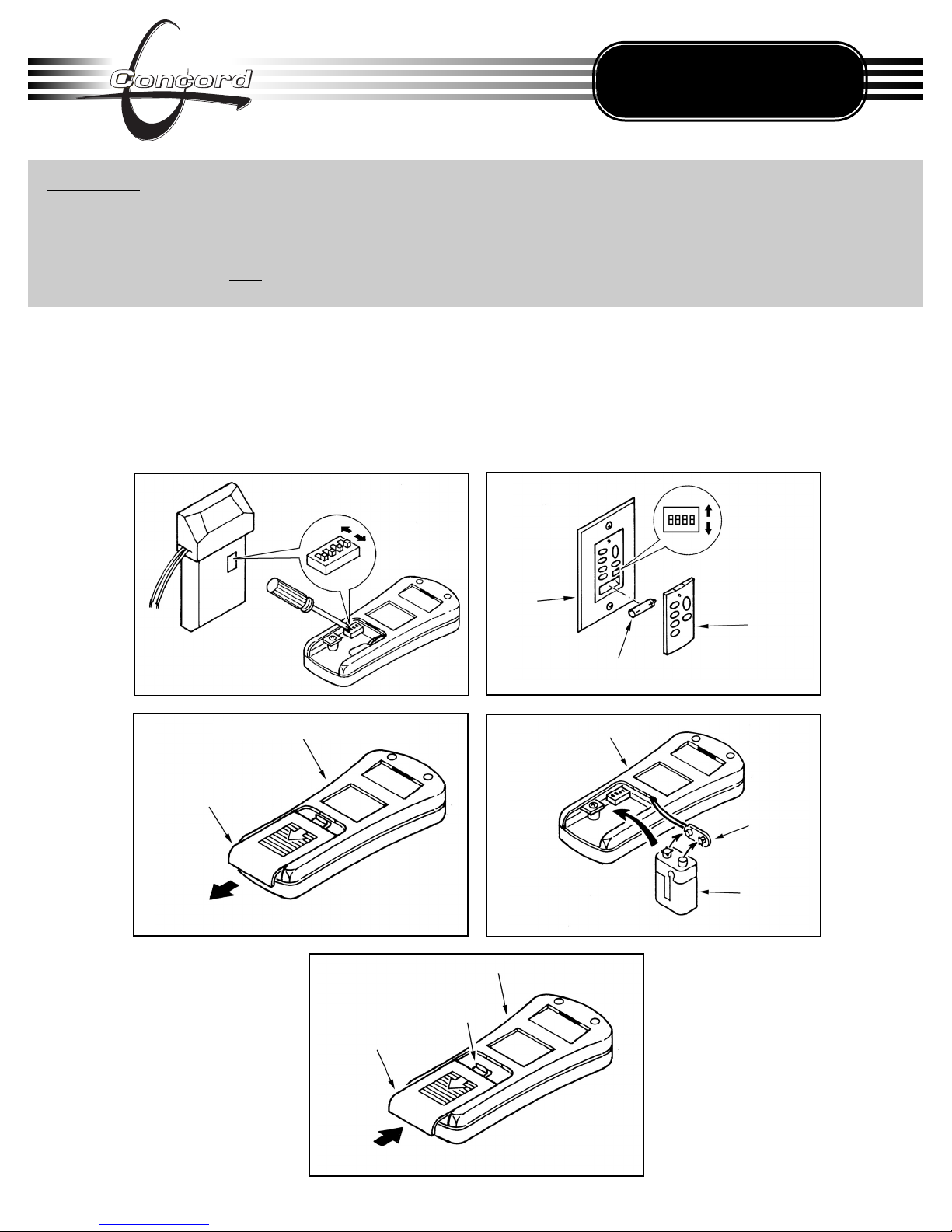
BEFORE BEGINNING INSTALLATION STEPS:
Locate the Hand-held Remote Control Transmitter, the Receiver Unit, and the Wall Control. These three items have a
block of dip switches inside them. See illustrations “i” and “ii” to locate the block of dip switches. Make sure the
switches in all three units are aligned exactly the same way. This system will not function properly unless all switches
are set the same. Insert 1-12 volt battery into the Wall Control Unit (see illustration ii). Insert 1-9 volt battery into the
compartment of the Hand-held Remote Control Transmitter (see illustrations “iii”, “iv” & “v”).
Figure i
Hand-Held Transmitter
Battery Compartment
Hand-Held Transmitter
Battery
Te rm inal
9 volt
Battery
Battery
Compartment
Lock Clip
Hand-Held
Transmitter
Figure ii
Figure iii (Open)
Figure iv (Insert Battery)
Figure v (Close)
- 1 -
12 volt Battery
Cover
Wall
Control
(Revised 05.02.2007)
Page 2
- 2 -
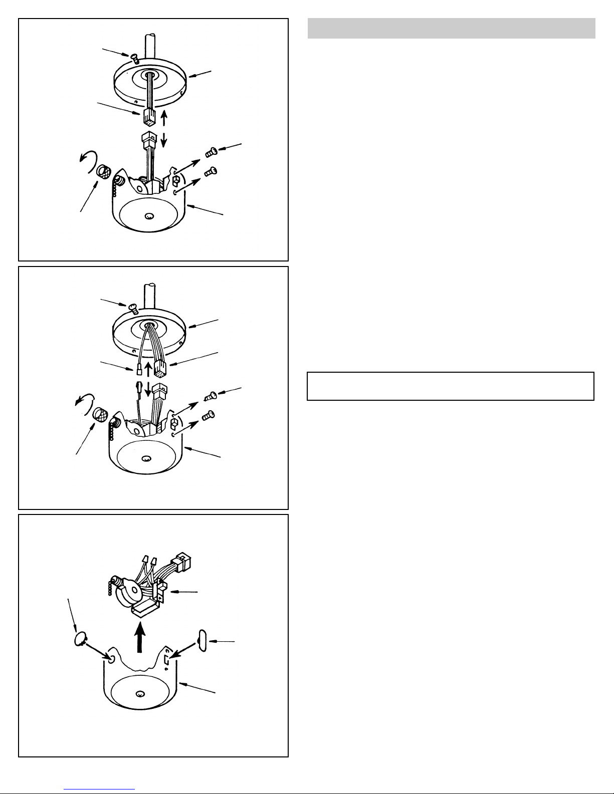
- Unscrew the metal sleeve where the pull chain comes out of the switch
housing (see figure A).
-Remove the speed switch from the hole.
-Next, remove the 2 small screws holding the forward/reverse switch in
place (see figure A).
-Now remove the forward/reverse switch from the hole.
-You are now able to remove the entire contents of the switch housing
unit (see figure C).
-Place the plastic caps supplied into the holes left by the speed switch
and forward/reverse switch (see figure C).
Figure A
Figure B
Figure C
Screw (3)
Mounting Plate
Molex
Switch
Housing
Remove Wire Bundle
Reverse
Switch
Screw (2)
Sleeve
Screw (3)
Mounting Plate
Molex
Reverse
Switch
Screw (2)
Switch
Housing
Sleeve
Pigtail Connector
Plug
Switch Housing
Plug
Option to remove wiring from switch housing
NOTE: If your fan has uplights or motor center band lighting, your
switch housing will look like figure B.
Page 3
WARNING:
For fans with uplighting or lighted motor housing, before disconnecting fan to install
Remote Control, tur
n all lights on HIGH.
STEP 1
The Switch Housing has three (3) screws around the top. Loosen the 3 screws. Rotate the Switch
Housing Unit to the left and remove. Unplug the Molex connector (see figure 1A). If you have
a light kit already attached to the fan, you may leave it attached. Simply remove the wire nuts
and disconnect the wires to the light kit. If you are installing a light fixture to the fan, do this now
according to the instructions supplied with the light kit. Do not however, connect any of the light
kit wires at this point.
NOTE: If your fan has uplight or motor center band lighting you will
have to unplug pigtail connector also (see figure 1B).
You will find 2 capacitors in your kit. Choose the capacitor that corresponds
with your fan model name (see chart below) then proceed to Step 2.
STEP 2
Make the following connections and place RM-08 wire bundle into the empty switch
housing. Remove paper backing from stickers to secure reverse module and capacitor to the bottom of the shell (see figure 2).
CONNECTIONS (see figure 2):
-Attach the WHITE Module wire to the WHITE
(Un-marked) Capacitor wire.
-Attach the RED wire from Molex plug to the RED
Capacitor wire.
-If your fan has a light kit attached, connect the BLUE Lite Kit
to the BLUE Molex
plug wire and the WHITE Lite Kit
wire to the WHITE Module wire.
-If no light is installed, the second WHITE
Capacitor wire (marked “For Light”)
remains unconnected.
- 3 -
Figure 1A
Figure 1B
Switch Housing Unit
RED Wire
Screw (3)
Mounting
Plate
Molex
Switch
Housing
Figure 2
Reverse
Module
BLUE Lite
Kit Wire
from Molex
Pigtail
Connector
WHITE Wire
Capacitor
RED
Wire
WHITE Module
Wire
WHITE Lite
Kit Wire
Screw (3)
Pigtail
Connector
Mounting
Plate
Molex
Switch
Housing
Fan With
Uplight only
Blue Wire
FAN CAPACITOR
“All About Looks” •
Aracruz •
Bamboo Breeze •
Boardwalk (indoor only) •
Calavera •
California •
Capetown •
Corinthian •
Decorama(”) •
Designer Gallery •
Dynasty •
Eden •
Elements •
Fernleaf Breeze •
Florence •
Formosa •
French Quarter •
Grandeville •
Grecian Isle •
Hearthside (”) •
Hillsboro •
Ivory Coast •
Le Cage •
Madison •
Navigator •
New Yorker •
Molex Plug
BLUE Lite Kit
Wire from Molex
FAN CAPACITOR
Palmleaf Breeze •
Portofino •
Ponderosa •
Quarry Breeze •
Ready Loc •
Roman Isle •
Roosevelt •
Sheraton •
Vineyard •
Visionaire •
Voyager •
Windsor •
Windswept •
Winford •
Page 4

- 4 -
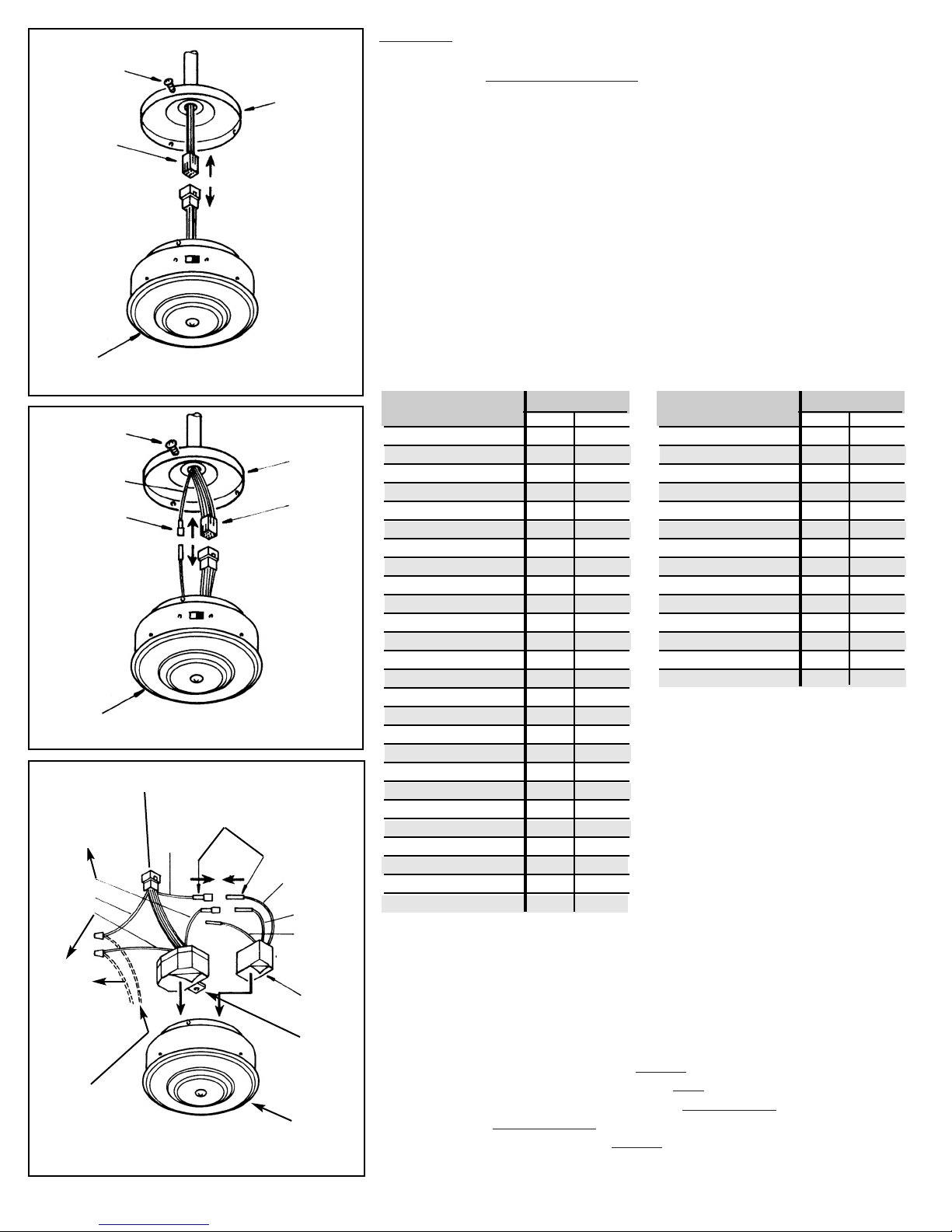
NOTE: If your fan has uplight or motor center band lighting you MUST connect the
WHITE Capacitor wire (marked “For Light”) to the BLUE
wire coming down from fan
(see figure 3B).
STEP 3
Connect the Molex plug from the switch housing unit to the end from the fan.
These plugs are notched and will connect in one direction only. Match the
colored sides and push together. The Switch Housing has 3 slotted holes
around the top. Align these holes with the three screws on the mounting plate.
Push the Switch Housing up and rotate to the right so the screws are at the far
left of the horizontal slot.
Tighten each screw (see figure 3A).
STEP 4: Install Mounting bracket
Loosen the two canopy mounting screws on the downside face of the mounting bracket. Back them out about half way. This will allow for easier installation of the ceiling canopy later.
Install the mounting bracket onto the electrical junction box in the ceiling
using 2 machine screws, 2 washers and 2 lock washers (see figure 4). The
mounting bracket has slotted holes to enable it to move sideways for proper
alignment.
Make sure the mounting bracket is centered over the electrical junction box
and that it is securely attached.
NO MOVEMENT SHOULD OCCUR BETWEEN THE MOUNTING
BRACKET AND THE ELECTRICAL JUNCTION BOX.
Pull the electrical wires in the junction box down and through the mounting
bracket.
STEP 5 (see figure 4)
-Attach the WHITE wire from the junction box to the WHITE wire from the
receiving unit.
-Attach the BLACK wire from the junction box to the BLACK
wire from the
receiving unit.
-Now connect the GROUND wire from the mounting bracket to the GROUND
wire in the ceiling junction box.
NOTE: Make sure and use wires nuts on these connections. DO NOT USE
PLASTIC TAPE.
Molex
Switch
Housing
Molex
White
Black
Receiving
Unit
Junction Box
Mounting
Bracket
Washer
Washer
Screw
Figure 3A
Mounting
Plate
Molex
Screw (3)
Switch
Housing
Molex
Figure 3B
BLUE From
Uplight
WHITE Wire
marked “For Light”
Figure 4
Page 5

- 5 -
STEP 6: Hanging the fan body
Notice the half ball on the end of the support rod is grooved down one side.
This Keyway fits over the small keyway pin on the inside of the mounting
bracket and keeps the ceiling fan from spinning on the mounting bracket.
Lift the fan and place the half ball in the center of the mounting bracket with
the keyway pin inserted into the keyway on the ball. Turn the fan left and
right slightly to make sure it is seated on the bracket with the keyway pin in
the keyway (see figure 5).
Trim the lead wires, leaving about six (6) inches of each wire extending from
the support rod.
STEP 7: Making the electrical connection
TURN OFF THE ELECTRICITY BEFORE PROCEEDING!
Make electrical connections from the fan to receiving unit in mounting bracket
(see figure 6a and 6b).
-Attach the WHITE wire from the fan to the WHITE
wire from receiving unit.
-Attach the BLACK wire from the fan to the BLACK
wire from receiving
unit.
-Attach the BLUE wire from the fan to the BLUE
wire from receiving unit.
NO
TE:
-If your fan has uplighting you will have an ORANGE or GRAY (on some
models) wire coming out of the fan. Connect this ORANGE or GRAY wire
from the fan to the ORANGE or GRAY wire on the Receiving Unit (see
figure 6a).
-If your fan has NO
Uplight, cap off the ORANGE or GRAY wire from
receiving unit (see figure 6b).
Position the receiving unit inside of the mounting bracket and feed the 4 wires
from the receiving unit down through the mounting bracket (see figure 5).
STEP 8: Install Ceiling Canopy
Lift the ceiling canopy up into place covering the mounting bracket.
Push the canopy up so the screws come through the mounting holes in the
canopy. Rotate the canopy slightly and tighten the screws (see figure 7).
Ceiling
Mount
Bracket
Canopy
Canopy
Screw
Figure 5
Mounting
Bracket
Receiving
Unit
Support
Rod
Figure 6b - Fan with no Uplighting (Cap OFF)
Figure 7
Ground
Black
White
Ground
Blue
Orange or
Gray
(Cap OFF)
White
Blue
Black
Figure 6a - Fan with Uplighting
Ground
Black
White
Ground
Blue
Orange
or Gray
White
Blue
Black
Page 6

- 6 -
Remove the wall switch plate cover and then remove the ON/OFF switch from the switch box (see
figure A). Pull the switch out of the box until you can see the wire nuts connecting the two wires
in the wall to the two wires on the switch. Now remove the wire nuts and disconnect the wires
from the switch. Re-connect the 2 switch wires together and tuck back in switch box to allow room
for RM-08. Replace wire nuts.
Push the Control Unit into the switch box and secure it with the two screws at each end of the unit
(this procedure is the same as if you were to put the original wall switch back into the wall). Now
attach the face plate to the Wall Control (see figure B).
Next, please see the Operation Instruction.
Reset your circuit breaker.
Figure A
Figure B
Mounting
Screw
Wall
Plate
Mounting
Screw
Old ON/OFF
Switch
Switch
Box
Ground
Wire
Switch Box
Wall Plate
Screw
Wall Control Unit
(This unit replaces the current ON/OFF switch)
Installing the Wall Control
Before you begin, TURN OFF THE ELECTRICITY
(at the main circuit panel or fuse box). If you feel
unsure of this procedure, have a qualified electrician
install this unit.
Screw
Switch
Wires
Page 7

- 7 -
Operation Instr
uctions
1. WALL CONTROL (see drawing below for the following instructions)
Speed Control
Press HI, MED, or LOW button to start the fan.
Press REV button to reverse air flow direction.
Press Fan OFF to stop the fan.
Light Control
Press DOWN button to turn on the bottom
fan lights. Press and hold for dimming feature.
Press UP button to turn on the top
fan lights. Press and hold for dimming feature.
NO
TE: The Remote Control Transmitter comes with a bracket
that can be mounted in any convenient place you choose. Next to
a light switch in the same room as the ceiling fan is a good place.
Attach the bracket with the two screws provided.
A.The Remote Control Transmitter
Transmitter
Mounting Bracket
Mounting Screw
B. Remote Control
Light Button UP
Speed Control
Press HI, MED, or LOW button to start the fan.
Press FOR/REV button to desired direction.
Press OFF to stop the fan.
Light Control
-Press Light button down
to turn on the bottom fan lights.
Press and hold for dimming feature.
-Press Light button up to turn on the top fan lights.
2. REMOTE CONTROL (see drawing below for the following instructions)
Light Button DOWN
Page 8

© Great 2000 Enterprises, Inc., 2007 • ALL RIGHTS RESERVED •
No part of this publication may be produced, transmitted, transcribed, stored in a retrieval system, or translated into any language
in any form by any means without the written permission of Great 2000 Enterprises, Inc..
Concord Fans and Lighting is a division of Great 2000 Enterprises, Inc.
®
 Loading...