

Page 1

ASSEMBLY MANUAL
1
PRECISION SHANK DRILL
Printed in USA (74363) 6/19
Page 2

AGCO-Amity JV LLC LIMITED WARR ANTY TERMS AND CONDITIONS – UNITED STATES AND CANADA
2
EFFECTIVE FOR EQUIPMENT RETAILED AND DELIVERED AFTER JUNE 1, 2018
WHAT IS WARRANTED AGCO Amity JV warrants its new equipment to be free of defects in material and workmanship at time of delivery to the first retail
purchaser, renter, or lessee. These terms apply to all Wishek, Wil-Rich, and Amity brands of new equipment originally marketed in the United States and
Canada.
WARRANTY PERIOD
• 12 Months from the date of delivery to the first retail purchaser, renter or lessee.
• 483 Disk Chisel, Field Cultivator, and Disk Cultivators: 3 years on main frames, wing frames, and shank assemblies
• Precision Shank Drill: 3 years on main frame, wing frame, and rockshafts.
EXCEPTIONS FROM THIS WARRANTY
• Freight Charges - This warranty does not cover freight charges.
• Improvements, Changes, or Discontinuance AGCO Amity JV reserves the right to make changes and improvements in design or changes in
specifications at any time to any product without incurring any obligations to owners of products previously sold.
• Repairs and Maintenance Not Covered Under Warranty - This warranty does not cover conditions resulting from misuse, natural calamities,
use of non-AGCO-Amity JV parts, negligence, alteration, accident, use of unapproved attachments, usage which is contrary to the intended
purposes, or conditions caused by failure to perform required maintenance. Replacement of Wear or Maintenance items (unless defective) such as
but not limited to, filters, hoses, belts, lubricants, light bulbs, wheel alignment, tightening of nuts, belts, bolts, and fittings, service tune-up,
computer parameter adjustments and general adjustments which may from time to time be required are not covered.
• Rubber Tire Warranty - Rubber tires are warranted directly by the respective manufacturer only and not by AGCO Amity JV.
• Satellite Outages - Interruptions in satellite interfaces and satellite communications are outside the control of this product and are not covered by
this warranty. The company is not responsible for issues or degradation of system performance resulting from such interruptions in satellite
interfaces and satellite communications where the issues are not related to defects in this product.
OWNER’S OBLIGATION
It is the responsibility of the Owner to transport the equipment or parts to the service shop of an authorized AGCO Amity JV Dealer or alternatively to
reimburse the Dealer for any travel or transportation expense involved in fulfilling this warranty. This Warranty does NOT cover rental of replacement
equipment during the repair period, damage to products which have been declared a total loss and subsequently salvaged, overtime labor charges, freight
charges for replacement parts, or special handling requirements (such as, but not limited to, the use of cranes).
EXCLUSIVE EFFECT OF WARRANTY AND LIMITATION OF LIABILITY
THIS WARRANTY IS IN LIEU OF ALL WARRANTIES OF MERCHANTABILITY, FITNESS FOR A PURPOSE OR OTHER REPRESENTATIONS, WARRANTIES
OR CONDITIONS, EXPRESSED OR IMPLIED. The remedies of the Owner set forth herein are exclusive. The Company neither assumes nor authorizes any
person to assume for it any other obligation or liability in connection with the sale of covered machines. Correction of defects, in the manner and for applicable
period of time provided above, shall constitute fulfillment of all responsibilities of AGCO Amity JV to the Owner, and AGCO Amity JV shall not be liable for
negligence under contract or in any manner with respect to such machines. IN NO EVENT SHALL THE OWNER BE ENTITLED TO RECOVER FOR INCIDENTAL,
SPECIAL OR CONSEQUENTIAL DAMAGES SUCH AS BUT NOT LIMITED TO, LOSS OF CROPS, LOSS OF PROFITS OR REVENUE, OTHER COMMERCIAL
LOSSES, INCONVENIENCE OR COST OF RENTAL OR REPLACEMENT EQUIPMENT.
Some States or Provinces do not permit limitations or exclusions of implied warranties or incidental or consequential damages, so the limitations or exclusions in this warranty may
not apply.
“AGCO Amity JV” AS REFERRED TO HEREIN WITH RESPECT TO SALES IN: UNITED STATES and CANADA: AGCO Amity JV LLC
PO Box 1030
Wahpeton, ND 58074
Additional Warranty Information
New Equipment Warranty - Equipment is eligible for warranty service only if it qualifies under the provisions of the New Equipment Warranty. The selling
dealer will deliver this Warranty to the original retail purchaser at the time of sale, and the dealer will register the sale and Warranty with AGCO Amity JV
LLC.
Subsequent Owners - This Warranty covers the first retail purchaser and all subsequent owners of the equipment during the specified warranty period.
Should the AGCO Amity JV Dealer sell this equipment to a subsequent owner, the Dealer must deliver the warranty document to the subsequent owner so the
subsequent owner can register ownership with AGCO Amity JV and obtain the remaining warranty benefits, if available, with no intermission in the Warranty
Period. Subsequent Owner Procedure will apply. It is the responsibility of the subsequent owner to transport the equipment to the service shop of an
authorized AGCO Amity JV Dealer or alternatively to reimburse the Dealer for any travel or transportation expense involved in fulfilling this warranty. This
Warranty does NOT cover charges for rental or replacement equipment during the repair period, products which have been declared a total loss and
subsequently salvaged, overtime labor charges, freight charges for replacement parts, or units sold at auction.
Warranty Service - To be covered by Warranty, service must be performed by an authorized AGCO Amity JV Dealer. It is recommended that you obtain
warranty service from the Dealer who sold you the equipment because of that Dealer’s continued interest in you as a valued customer. In the event this is
not possible, warranty service may be performed by any other authorized AGCO Amity JV Dealers in the United States or Canada. It is the responsibility
of the Owner to transport the equipment to the service shop of an authorized AGCO Amity JV Dealer or alternatively to reimburse the Dealer for any travel or
transportation expense involved in fulfilling this warranty.
Maintenance Service - The Owner’s Manual furnished to you with the equipment at the time of delivery contains important maintenance and service information.
You must read the manual carefully and follow all the maintenance and service recommendations. Doing so will result in greater satisfaction with your equipment
and help avoid service and warranty problems. Please remember that failures due to improper maintenance of your equipment are not covered by warranty.
Maintenance Inspections - To insure the continued best performance from your agricultural equipment, we recommend that you arrange to make your
equipment available to your selling Dealer for a maintenance inspection 30 days prior to warranty expiration.
Page 3

PERSONAL SAFETY IS IMPORTANT!
3
ALL PERSONNEL INVOLVED WITH THE ASSEMBLY AND/OR OPERATION OF THIS
EQUIPMENT MUST BE INFORMED OF PROPER SAFETY PROCEDURES. OPERATOR’S/
ASSEMBLY MANUALS PROVIDE THE NECESSARY INFORMATION. IF THE MANUAL
IS LOST FOR A PARTICULAR IMPLEMENT, ORDER A REPLACEMENT AT ONCE.
OPERATOR’S AND ASSEMBLY MANUALS ARE AVAILABLE AT NO CHARGE UPON REQUEST.
The Safety Alert symbol iden-
This Safety Alert symbol
means ATTENTION! BE-
COME ALERT YOUR
SAFETY IS INVOLVED!
tifies important safety messages on the Amity Precision Shank Drill and in this
manual. When you see this
symbol, be alert to the possibility of personal injury or death.
Follow the instructions in the
safety message.
3 Big Reasons
SIGNAL WORDS:
Note the use of the signal
words
DANGER, WARNING
and CAUTION
messages. The appropriate
signal word for each message
has been selected using the
following guidelines:
with the safety
Why is SAFETY important to you?
Accidents Disable and Kill
Accidents Cost
Accidents Can Be Avoided
DANGER
An immediate and specific hazard which WILL
result in severe personal
injury or death if the
proper precautions are
not taken.
ADDRESS INQUIRIES TO: AGCO Amity JV LLC
2800 7th Avenue North
Fargo, ND 58102
PH (701) 232-4199 FAX (701) 234-1716
WARNING
A specific hazard or unsafe practice which
COULD result in severe
personal injury or death if
the proper precautions
are not taken
CAUTION
Unsafe practices which
COULD result in personal
injury if proper practices
are not taken, or as a reminder of good safety
practices.
Page 4

Table of contents
4
Precision Shank Drill
1 Safety .....................................................................8
1.1 Introduction .........................................................8
1.1.1 Safety alert symbol ................................................8
1.1.2 Safety messages ..................................................8
1.1.3 Informational messages .. ..........................................8
1.1.4 Safety signs ...................................................... 8
1.1.5 A word to the operator ..............................................9
1.1.6 This manual .. ..................................................10
1.2 Operation . ........... ............ ............. ............ ...... .11
1.2.1 Prepare for operation . ............ ............. ............ .......11
1.2.2 General information ....... .... .. ............. ... ............ ....11
1.2.3 Personal protective equipment ....................................... ..12
1.2.4 Seat instructions .................................................13
1.2.5 Shield and guards ......................... .......................13
1.2.6 Exhaust warning . .... ............ ............. ............ ......13
1.2.7 Flying debris .................................................... 14
1.2.8 Agricultural chemicals .............................................14
1.3 Travel on public roads ............. ............ ............. ...... ..15
1.4 Maintenance .. ..... ............ ............. ............ ...........17
1.4.1 General maintenance information .....................................17
1.4.2 Fire prevention and first aid .........................................18
1.4.3 High pressure leaks ...... ............ ............. ............ ....19
1.4.4 Tire safety ...................................................... 20
1.4.5 Replacement parts ................................................20
1.5 Transport locks ........... ............. ............ ............. ... 21
1.6 Marker lamps ...................................................... 22
1.7 Safety sign location .......... ............ ............. ............. 23
1.7.1 Safety sign descriptions .........................................24-28
2 Introduction ..............................................................29
2.1 Introduction ........................................................30
2.1.1 Units of measurement .............................................30
2.1.2 Replacement parts ................................................30
2.1.3 Intended use ....................................................30
2.1.4 Proper disposal of waste ...........................................30
2.2 Machine identification ..............................................32
2.2.1 Serial number plate location .........................................32
2.2.2 Serial number description ........................................32-33
Page 5

Table of contents
5
Assembly ................... .............. ...........................34-35
3.
Mainframe................................................36
Front inner wing anchor/rest............................................37
Front hitch pivot....................................................... 38
Front caster mount.....................................................39
Front caster mount-mainframe..........................................40
Front hitch pivot assembly..............................................41
Front lift cylinders-mainframe............................................42
Front hitch...............................................43
Hydraulic jack.........................................................44
Docking station........................................................45
Rear inner wing anchor/rest 51ft.........................................46
Rear inner wing anchor/rest 61ft.........................................47
Inner wing 51ft..........................................................48
Inner wing 61ft..........................................................49
Outer wings..............................................50
Outer wing fold linkage.................................................51
Outer wing latch........................................................52
Outer wing latch system................................................53
51ft inner wing fold cylinder mounts.....................................54
51ft inner wing fold cylinder rod connection/wing rest.....................55
61ft inner wing fold cylinder mounts......................................56
51ft outer wing fold cylinders ..................................57
61ft outer wing fold cylinders............................................58
Rear axle..............................................................59
Rear hitch.............................................................60
Rear lift cylinders-mainframe............................................61
Lift axle-rear wing.......................................................62
Rear lift cylinder-inner & outer wing ......................................63
Front lift assembly left-inner & outer wing.........................64
Front lift assembly right-inner & outer wing...............................65
Front lift cylinder-inner & outer wing.....................................66
Row unit-frame mount..................................................67
Row unit placement-mainframe.........................................68
Row unit placement-51ft inner wing......................................69
Row unit placement-61ft inner wing......................................70
Row unit placement-51ft outer wing......................................71
Row unit placement-61ft outer wing......................................72
Page 6

Table of contents
6
3. Assembly-continued
Hose channel-mainframe..................................... 73
Hose channel-inner wing...............................................74
Hose channel-front hitch...............................................75
Down pressure valve...................................................76
Down pressure valve mount.............................................77
Hydraulic hose assembly sequence......................................78
51ft lift hydraulics...............................
61ft lift hydraulics.... ............. ............ ............80
51 & 61ft lift hydraulics.. ... .. ........................................81
51ft wing fold hydraulics................................................82
51ft wing fold hydraulics................................................83
61ft wing fold hydraulics................................................84
61ft wing fold hydraulics..................................... ............85
Down pressure hydraulics-DP block......................................86
Down pressure hydraulics-DP block.............................87
Down pressure hydraulics-mainframe.. ... .. ............................88
Down pressure hydraulics-inner wing....................................89
Down pressure hydraulics-outer wing....................................90
Rear hitch hydraulics................................................91-92
Rear hitch hydraulic & electrical fittings..................................93
Front light mount........................................................94
SMV sign & stop collars ......................................95
........................79
Rear lights, light module, & lift switch....................................96
Lift switch... . .......................................................97-99
Bleeding air from the hydraulic lift system...............................100
Bleeding air from the hydraulic fold system..............................101
Leveling the mainframe.................................................102
Leveling the wings ..................................................103-104
Model decals-front hitch.....................................105
Model decals-outer wing................................................ 106
Tire air pressure....... ...............................................107
Page 7

Page Left Blank Intensionally
7
Page 8

1. Safety
8
1.1 Introduction
1.1.1 Safety alert symbol
The safety alert symbol means Attention! Become
Alert! Your Safety Is Involved!
Look for the safety alert symbol both in this
manual and on safety signs on this machine. The
safety alert symbol will direct your attention to
information that involves your safety and the
safety of others.
1.1.2 Safety messages
The words DANGER, WARNING or CAUTION are
used with the safety alert symbol. Learn to
recognize these safety alerts and follow the
recommended precautions and safety practices.
Fig. 1
DANGER:
Indicates an imminently hazardous
situation that, if not avoided, will
result in DEATH OR VERY SERIOUS
INJURY.
WARNING:
Indicates a potentially hazardous
situation that, if not avoided, could
result in DEATH OR SERIOUS
INJURY.
CAUTION:
Indicates a potentially hazardous
situation that, if not avoided, may
result in MINOR INJURY.
Fig. 2
1.1.3 Informational messages
The words important and note are not related to personal safety, but are used to give additional
information and tips for operating or servicing this equipment.
IMPORTANT: Identifies special instructions or procedures which, if not strictly observed, could result in
damage to or destruction of the machine, process, or its surroundings
NOTE: Identifies points of particular interest for more efficient and convenient repair or operation.
1.1.4 Safety signs
WARNING:
Do not remove or obscure safety signs. Replace any safety signs that are not readable or
are missing. Replacement signs are available from your dealer in the event of loss or
damage. The actual location of the safety signs is illustrated at the end of this section.
Keep signs clean by wiping off regularly. Use a mild soap and water solution if necessary.
Page 9
1. Safety
9
If parts have been replaced or a used machine has been purchased, make sure all safety signs are present
and in the correct location and can be read. Illustrations of safety sign locations are located at the rear of
this section.
Replace any safety signs that can not be read, are damaged, or are missing. Clean the machine surface
thoroughly with a mild soap and water solution before replacing signs. Replacement safety signs are
available from your dealer.
1.1.5 A word to the operator
It is your responsibility to read and understand the
safety section in this manual and the manual for all
attachments before operating this machine.
Remember you are the key to safety. Good safety
practices not only protect you, but also the people
around you.
Study the content in this manual and make the
content a working part of your safety program.
Keep in mind that this safety section is written
only for this type of machine. Practice all other
usual and customary safe working precautions,
and above all remember - safety is your
responsibility. You can prevent serious injury or
death.
Fig. 3
This safety section is intended to point out some
of the basic safety situations that may be
encountered during the normal operation and
maintenance of your machine. This section also
suggests possible ways of dealing with these
situations. This section is not a replacement for
other safety practices featured in other sections of
this manual.
Personal injury or death may result if these
precautions are not followed.
Learn how to operate the machine and how to use
the controls properly.
Do not let anyone operate the machine without
instruction and training.
For your personal safety and the personal safety of
others, follow all safety precautions and
instructions found in the manuals and on safety
signs affixed to the machine and all attachments.
Use only approved attachments and equipment.
Make sure your machine has the correct
equipment needed by the local regulations.
WARNING:
An operator should not use alcohol or
drugs which can affect their alertness
or coordination. An operator on
prescription or 'over the counter'
drugs needs medical advice on
whether or not they can properly
operate machines.
Page 10

1. Safety
10
CAUTION:
If any attachments used on this
equipment have a separate Operator
Manual, see that manual for other
important safety information.
1.1.6 This manual
This manual covers general safety practices for this machine. The operator manual must always be kept
with the machine.
Right-hand and left-hand, as used in this manual, are determined by facing the direction the machine will
travel when in use.
The photos, illustrations, and data used in this manual were current at the time of printing, but due to
possible in-line production changes, your machine can vary slightly in detail. The manufacturer reserves the
right to redesign and change the machine as necessary without notification.
WARNING:
In some of the illustrations and photos used in this manual, shields or guards may have
been removed for clarity. Never operate the machine with any shields or guards removed.
If the removal of shields or guards is necessary to make a repair, they must be replaced
before operation.
Page 11
1. Safety
11
1.2 Operation
1.2.1 Prepare for operation
Read and understand all operating instructions and precautions in this manual before operating or servicing
the machine.
Make sure you know and understand the positions and operations of all controls. Make certain all controls
are in neutral and the park brake is applied before starting the machine.
Make certain all people are well away from your area of work before starting and operating the machine.
Check and learn all controls in an area clear of people and obstacles before starting your work. Be aware of
the machine size and have enough space available to allow for operation. Never operate the machine at
high speeds in crowded places.
Emphasize the importance of using correct procedures when working around and operating the machine.
Do not let children or unqualified persons operate the machine. Keep others, especially children, away
from your area of work. Do not permit others to ride on the machine.
Make sure the machine is in the proper operating condition as stated in the Operator Manual. Make sure
the machine has the correct equipment required by local regulations.
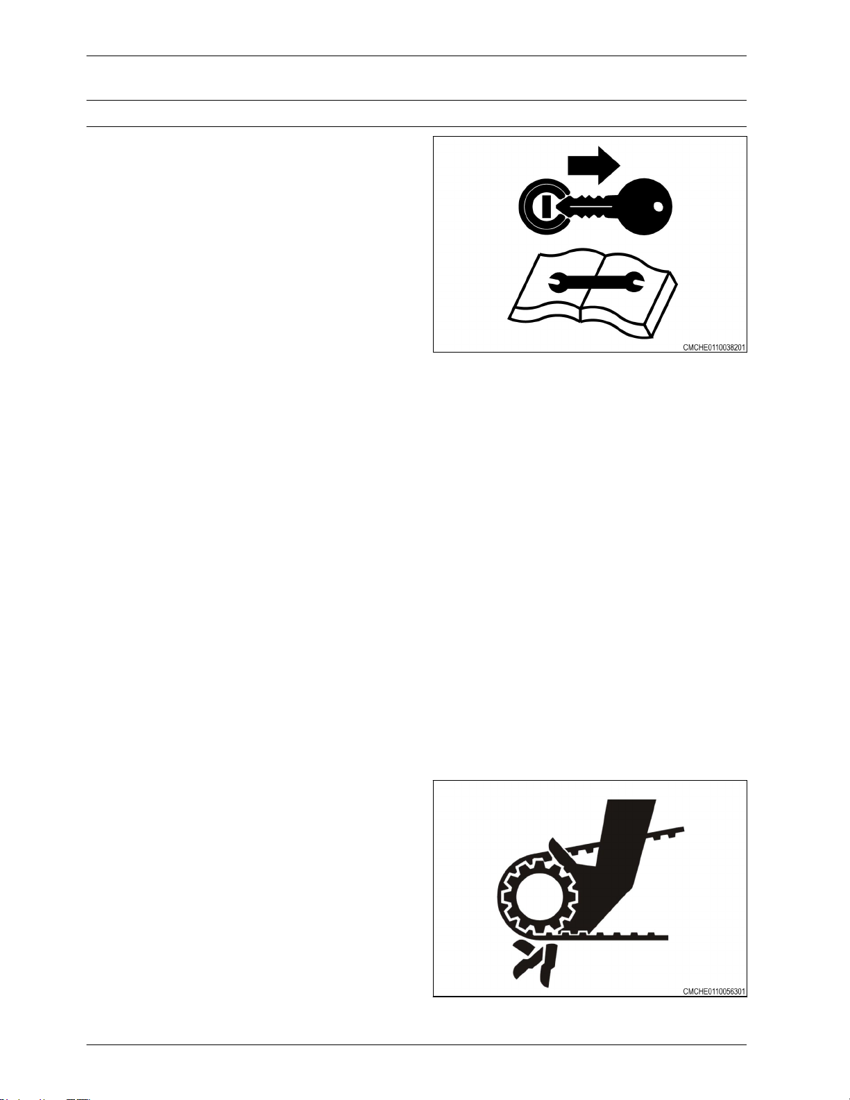
1.2.2 General information
When parking, park the machine and the tractor on
a solid level surface. put all controls in neutral and
apply the tractor park brake. Stop the tractor
engine and take the key with you.
Make sure the tractor and implement are in the
proper operating condition according to the
operator manuals. Make sure the tractor brakes
and the machine brakes are adjusted correctly.
The tractor must have enough weight and braking
capacity, especially when operating on roads and
terrain that is not even. Use a tractor of
recommended size and weight to tow the
machine. See the machine specifications for the
minimum tractor size and weight.
Tractor must be equipped with rollover protective
structure (ROPS) and a seat belt. use seat belt
during operation.
Do not dismount from moving machinery.
Always operate the machine with the terminal
turned on.
Never start the tractor with the PTO engaged or
terminal turned on.
Stay off slopes too steep for operation.
Where possible avoid operating the machine near
ditches, embankments, and holes. Reduce ground
speed when operating on rough, slippery, or
muddy surfaces and when turning or crossing
slopes.
Fig. 4
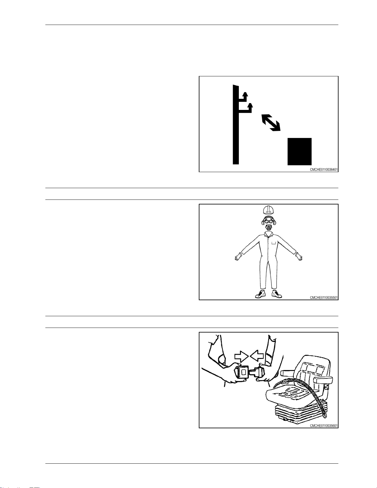
Be aware of the size of the machine and have
enough space available to allow for operation.
Page 12
1. Safety
12
Always lower the machine when not in use and
relieve the pressure in the hoses and cylinders.
Do not stand between the tractor and the
implement to install the hitch pin when the tractor
engine is running.
Avoid contact with electrical power lines. Contact
with electrical power lines can cause electrical
shock, resulting in very serious injury or death.
1.2.3 Personal protective equipment
Fig. 5
Wear all personal protective equipment (PPE) and
protective clothing issued to you or called for by
job conditions and country/local regulations. PPE
includes, but is not limited to, equipment to
protect eyes, lungs, ears, head, hands and feet
when operating, servicing, or repairing equipment.
Always keep hands, feet, hair, and clothing away
from moving parts. Do not wear loose clothing,
jewelry, watches, or other items that could
entangle in moving parts. Tie up long hair that can
also entangle in moving parts.
1.2.4 Seat instructions
Securely fasten the seat belt before operating the
machine. Always remain seated and have the seat
belt fastened while operating the machine.
Replace the seat belts when they become worn or
broken.
Never wear a seat belt loosely or with slack in the
belt system. Never wear the seat belt in a twisted
condition or pinched between the seat structural
members.
Fig. 6
When using the instructional seat, if equipped,
securely fasten the seat belt. The instructional seat
is to be used only to train new operators or
diagnose a problem. The instructional seat is only
intended for short periods of use. Extra riders,
especially children, are not permitted on the
machine.
Fig. 7
Page 13

When the instructional seat is used the machine
13
must be driven at a slower speed and on level
ground. Avoid quick starts, stops, and sharp turns.
Avoid driving on highways or public roads.
1.2.5 Shield and guards
All shields and guards must be in the correct
operating position and in good condition.
Do not open, remove, or reach around shields
while the engine is operating. Entanglement in
rotating belts and components can cause serious
injury or death. Stay clear of rotating components.
Do not operate the machine with the drive shaft
shields open or removed. Entanglement in rotating
drive shafts can cause serious injury or death. Stay
clear of rotating components.
1. Safety
Fig. 8
Make sure rotating guards turn freely.
1.2.6 Exhaust warning
Never operate the engine in a closed building
unless the exhaust is vented outside.
Do not tamper with or modify the exhaust system
with unapproved extensions.
Fig. 9
Fig. 10
Page 14
1. Safety
14
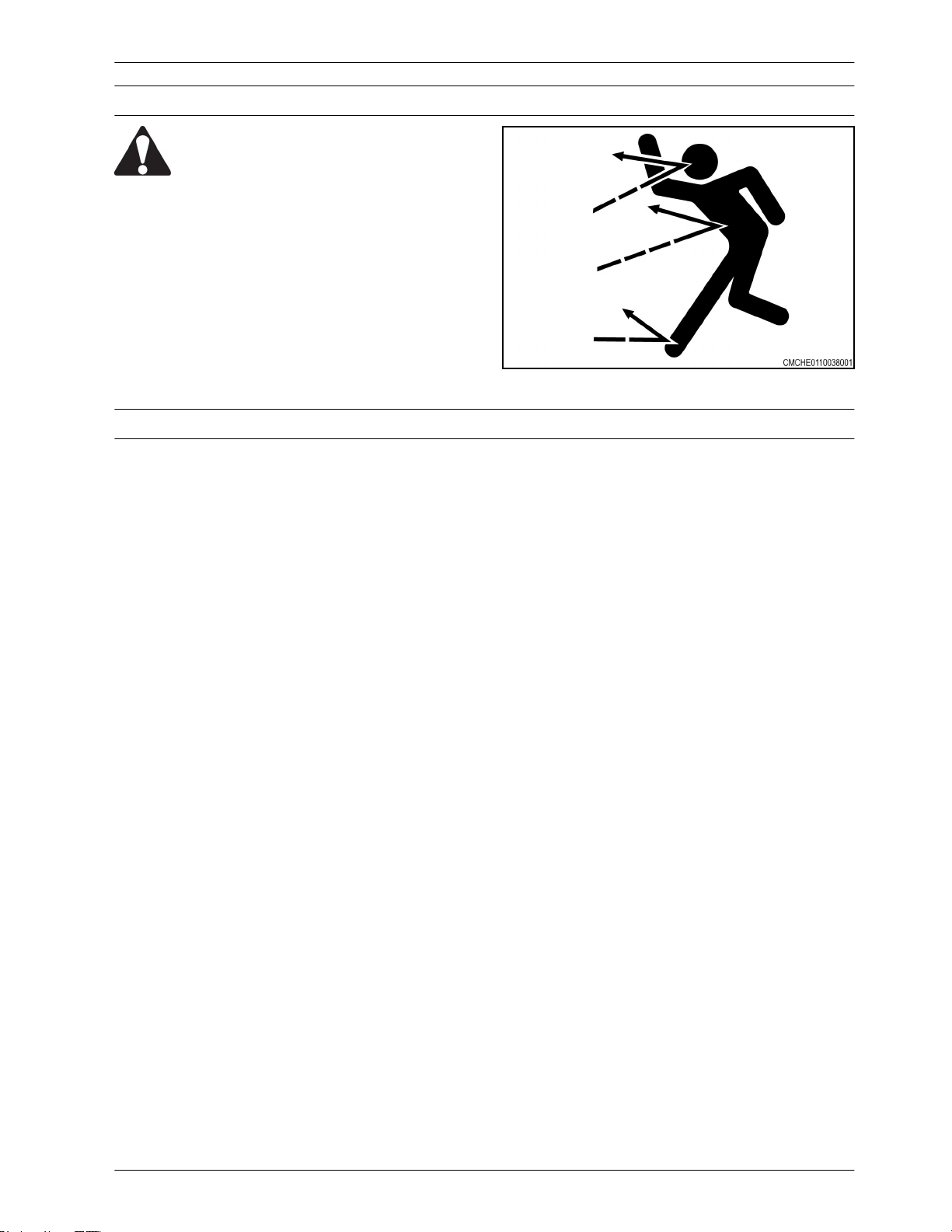
1.2.7 Flying debris
WARNING:
Be careful when operating along the
side of a road or building. Rocks or
other debris can be thrown from the
machine during operation possibly
resulting in injury.
Never stand near the machine during operation.
Debris can be thrown from the machine during
operation possibly resulting in injury.
Fig. 11
1.2.8 Agricultural chemicals
Agricultural chemicals can be very hazardous. Improper use of fertilizer, fungicides, herbicides, insecticides
and pesticides can injure people, plants, animals, soil and other people's property.
Always read and follow all manufacturers' instructions before opening any chemical container.
Even if you think you know the instructions, read and follow instructions each time you use a chemical.
Use the same precautions when adjusting, servicing, cleaning or storing the machine as used when
installing chemicals into the hoppers or tanks.
Inform anyone who comes in contact with chemicals of the potential hazards involved and the safety
precautions required.
Stand upwind and away from smoke from a chemical fire.
Store or dispose of all unused chemicals only in a manner as specified by the chemical manufacturer.
Page 15
1.3 Travel on public roads
15
Make sure you understand the speed, brakes,
steering, stability, and load characteristics of this
machine before you travel on public roads.
Use good judgment when traveling on public
roads. Maintain complete control of the machine at
all times. Never coast down hills.
The maximum speed of farm equipment is
governed by local regulations. Adjust travel speed
to maintain control at all times.
Familiarize yourself with and obey all road
regulations that apply to your machine. Consult
your local law enforcement agency for local
regulations regarding movement of farm
equipment on public roads. Use head lamps,
flashing warning lamps, tail lamps and turn signals,
day and night, unless prohibited by local law.
Make sure all the flashers are operating prior to
driving on the road. Make sure reflectors are
correctly installed, in good condition, and wiped
clean. Make sure the Slow Moving Vehicle (SMV)
emblem is clean, visible, and correctly mounted on
the rear of the machine.
1. Safety
Fig. 12
Lock brake pedals together (if equipped with dual
brake pedals) so both wheel brakes will be applied
at the same time.
Raise implements to transport position and lock in
place. Place all implements into narrowest
transport configuration.
Disengage the power take-off and differential lock.
With towed implements, use a proper hitch pin
with a clip retainer and safety transport chain.
Be aware of other traffic on the road. Keep well
over to your own side of the road and pull over,
whenever possible, to let faster traffic pass.
Be aware of the overall width, length, height, and
weight of the machine. Be careful when
transporting the machine on narrow roads and
across narrow bridges.
Page 16

1. Safety
16
Watch for overhead wires and other obstructions.
Avoid contact with electrical power lines. Contact
with electrical power lines can cause electrical
shock, resulting in very serious injury or death.
Fig. 13
Page 17
1. Safety
17
1.4 Maintenance
1.4.1 General maintenance information
Before doing any unplugging, lubricating, servicing,
cleaning, or adjusting:
• Park the machine on a solid level surface.
• Make sure all controls are in the neutral
position and apply the park brake.
• Make sure all implements and attachments
have been lowered to the ground.
• Stop the engine and take the key with you.
• Look and Listen! Make sure all moving parts
have stopped.
• Put blocks in front of and behind the wheels of
the machine before working on or under the
machine.
Do not leave the tractor or implement unattended with the engine running.
Do not pull crop or any other object from the machine while the machine engine is running. Moving parts
can pull you in faster than you can move away.
Fig. 14
Check all nuts and bolts periodically for tightness, especially wheel mounting hardware.
Do not attempt to service or adjust the machine until all moving parts have stopped.
Check all nuts and bolts periodically for tightness, especially wheel mounting hardware.
Be aware of the size of parts when doing service work. Never stand under or near a part being moved with
lifting equipment.
After unplugging, lubricating, servicing, cleaning, or adjusting the machine make sure all tools and
equipment have been removed.
Make sure electrical connectors are clean and free of dirt or grease before connecting.
Check for loose, broken, missing, or damaged parts. Make sure the machine is in good repair. Make sure
all guards and shields are in position.
Always raise implement, shut off tractor engine, apply the parking brake, shift to park position (or neutral)
remove the key and install the cylinder stops channels before working around the machine.
Avoid working under the machine. However, if it becomes unavoidable to do so, make sure the machine is
securely blocked and the cylinder lockup channels are in position.
When working around discs or shanks, be careful to not get cut on sharp edges.
Never service, check or adjust drive chains or belts
while the engine is running.
Fig. 15
Page 18
1. Safety
18
Do not operate the machine with the drive shaft
shields open or removed. Entanglement in rotating
drive shafts can cause serious injury or death.
Stay clear of rotating components.
Make sure rotating guards turn freely.
A loose yoke can slip off a shaft and result in injury
to persons or damage to the machine.
When installing a quick disconnect yoke, the
spring activated locking pins must slide freely and
be seated in the groove on the shaft. Pull on the
driveline to make sure the quick disconnect yoke
can not be pulled off the shaft.
Remove spilled oil, antifreeze or fuel immediately
from the steps, platform, and other access areas.
Keep all access areas clean and free of
obstructions.
Fig. 16
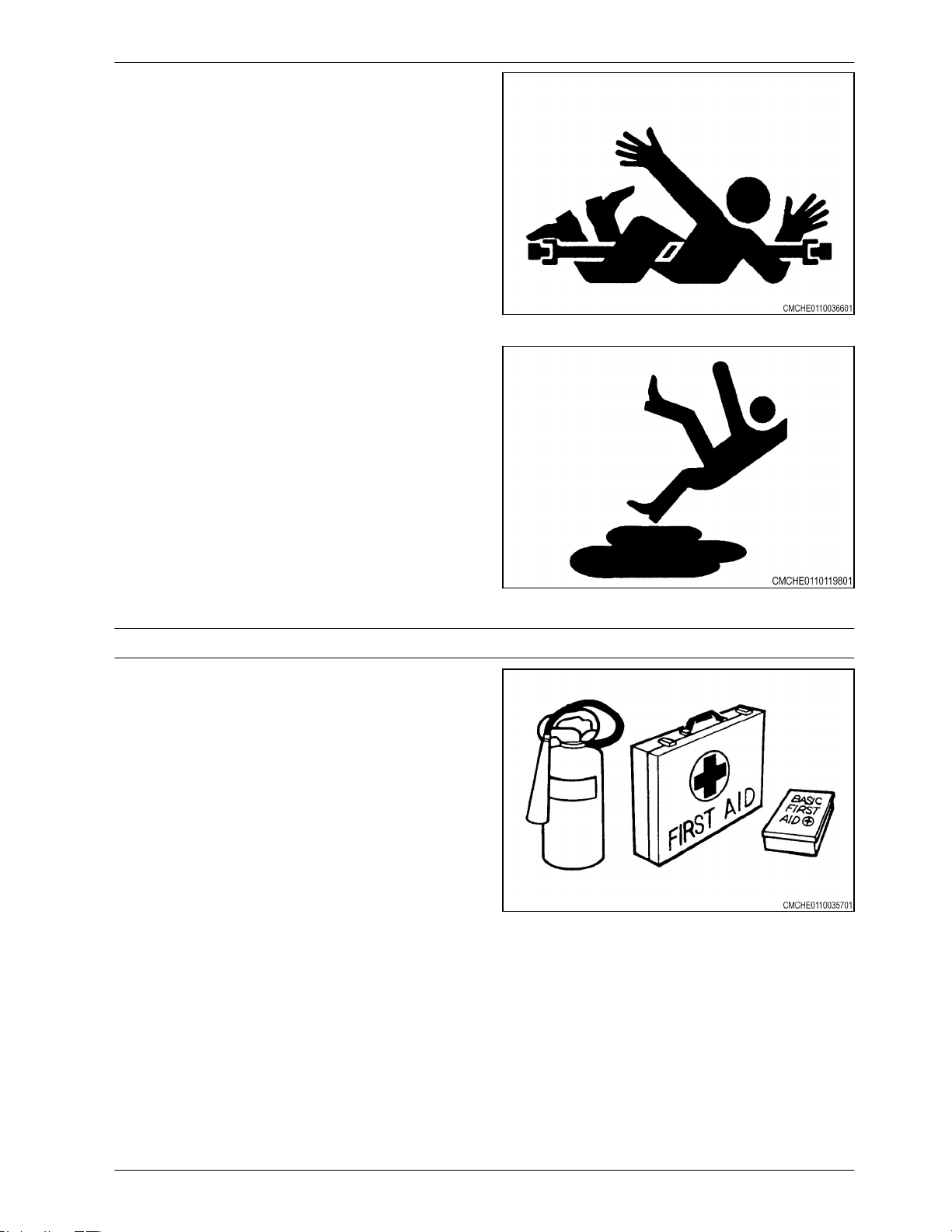
1.4.2 Fire prevention and first aid
Be prepared for emergencies.
Keep a first aid kit handy for treatment of minor
cuts and scratches.
Always carry one or more fire extinguishers of the
correct type. Check fire extinguishers regularly as
instructed by the manufacturer. Make sure fire
extinguishers are properly charged and in
operating condition.
Due to the nature of the crops this machine will
operate in, the risk of fire is of concern. Use a
water type fire extinguisher or other water source
for a fire in crop.
For fires involving anything other than crop, such
as oil or electrical components, use a dry chemical
fire extinguisher with an ABC rating.
Mount fire extinguishers within easy reach of
where fires can occur.
Frequently remove accumulated crop material
from the machine and check for overheated
components. Check the machine daily for any
noises that are not normal. Such noises could
indicate a failed component that can cause excess
heat.
Fig. 17
Fig. 18
Page 19
If any flame cutting, welding, or arc welding is to
19
be done on the machine or attachments, make
sure to clear any crop material or debris from
around the area. Make sure the area below the
work area is clear of any flammable material as
falling molten metal or sparks can ignite the
material.
If fire occurs stand upwind and away from smoke
from the fire.
1. Safety
Fig. 19
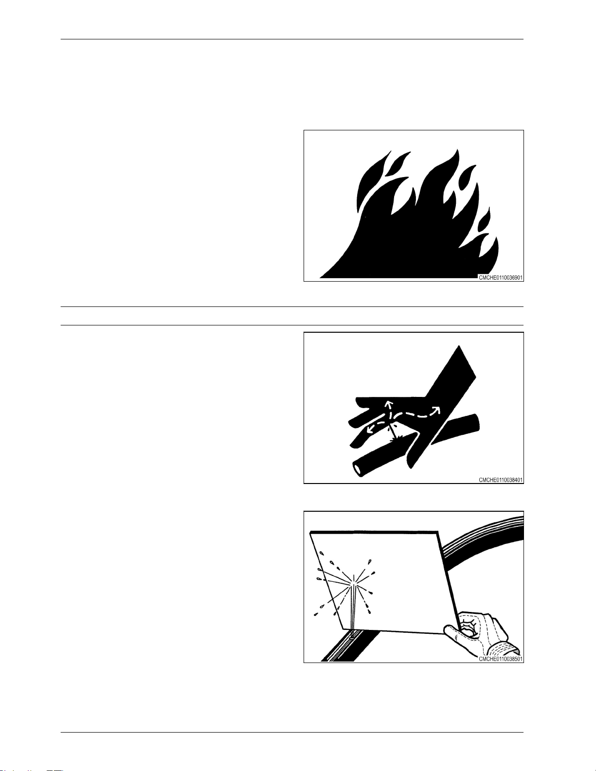
1.4.3 High pressure leaks
Fluid leaking from the hydraulic system or the fuel
injection system under high pressure can be very
hard to see. The fluid can go into the skin causing
serious injury.
Fluid injected into the skin must be surgically
removed within a few hours. If not removed
immediately, serious infection or reaction can
develop. Go immediately to a doctor who knows
about this type of injury.
Use a piece of cardboard or wood to search for
possible leaks. Do not use your bare hand. Wear
leather gloves for hand protection and safety
goggles for eye protection.
Relieve all pressure before loosening any hydraulic
lines. Relieve the pressure by lowering raised
equipment, shutting off accumulator valve, if
equipped, and shutting off the engine. Tighten all
connections securely before applying pressure.
Fig. 20
Fig. 21
Page 20

1. Safety
20
1.4.4 Tire safety
Check tires for cuts, bulges, and correct pressure.
Replace worn or damaged tires. When tire service
is needed, have a qualified tire mechanic service
the tire. Tire changing can be very hazardous and
must be done by qualified tire mechanic using
proper tools and equipment. See the
Specifications Section for the correct tire size.
Tire explosion and/or serious injury can result from
over inflation. Do not exceed the tire inflation
pressures. See the Specifications Section for the
correct tire pressure.
Do not inflate a tire that is seriously under inflated
or has been run flat. Have the tire checked by
qualified tire mechanic.
Do not weld on the rim when a tire is installed.
Welding will make an air/gas mixture that can
cause an explosion and burn with high
temperatures. This danger applies to all tires,
inflated or deflated. Removing air or breaking the
bead is not enough. The tire must be completely
removed from the rim prior to welding.
Fig. 22
When preparing a calcium chloride solution for
fluid ballast the tractor tires, never pour water onto
the calcium chloride. A chlorine gas can be
generated which is poisonous and explosive. This
can be avoided by slowly adding calcium chloride
flakes to water and stirring until they are dissolved.
When seating tire beads onto rims, never exceed
2.4 bar (35 psi) or the maximum inflation pressure
specified on the tire. Inflation beyond this
maximum pressure may break the bead, or even
the rim, with explosive force.
1.4.5 Replacement parts
Where replacement parts are necessary for
periodic maintenance and servicing, genuine
replacement parts must be used to restore your
equipment to original specifications.
The manufacturer will not accept responsibility for
installation of unapproved parts and/or accessories
and damages as a result of their usage.
Fig. 23
Page 21
1.5 Transport locks
21
The machine is equipped with transport locks and
depth stop collars. Use the transport locks and
depth stop collars in the operating position (1)
when moving the machine on roads. When not in
use, keep the transport locks and depth stop
collars in the storage position (2).
2
FRONT
1. Safety
1
2
701304
REAR
1
2
1
2
701303
Page 22
1.
22
Safety
1.6 Marker lamps
The machine has marker lamps that must be used
when moving the machine in the folded position
on roads.
The machine is equipped with two red lamps (1)
located toward the rear center of the machine.
The machine is equipped with two amber lamps
(1) located at the front outside edges of the folded
machine.
FRONT
1
REAR
1
701305
1
701305
1
Page 23
1. Safety
23
1.7 Safety sign location
8
2
1
2
2
8
1
1
8
2
1
8
7
4
3
5
2
1
1
1
1
2
2
9
2
6
2
1
1
2
8
1
2
2
1
8
Fig. 26
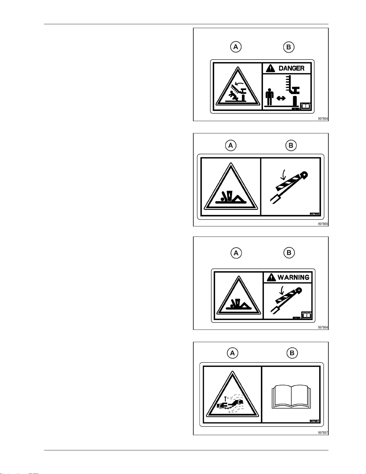
(1) Danger/Folding Wings
(2) Warning/Lockout
(3) Safety Decal Set
(4) Warning/Read Operator Manual
(5) Danger/High Line
(6) Slow Moving Vehicle
(7) Maximum Speed
(8) Reflector/Amber
(9) Depth Indicator Decal
(1) Danger/folding wings
Hazard (A): Overhead crushing hazard from
lowering or falling wing.
Avoidance (B): Stay clear of this area while
engine and machine are operating. For service
work, install the wing lock pins before getting under
the wing.
Fig. 27
Page 24
1. Safety
24
(2) Warning/lockout
Hazard (A): Crushing hazard.
Avoidance (B): Stay clear of this area while engine
and machine are operating. For service work,
install the wing lock pins before getting under the
wing.
Fig. 27
(3) Caution/safety chains
Hazard (A): Loss of machine control.
Avoidance (B): Install the safety chains when
connecting the machine to the tractor. Read the
operators manual for safety information and the
operating instruction before operating the
machine.
Fig. 28
Fig. 28
Fig. 29
Page 25
(4) Warning/negative tongue weight
25
Hazard (A): Negative tongue weight will cause the
tongue to rise immediately when disconnecting
the machine.
Avoidance (B): Stay clear of the tongue when
disconnecting the machine from the tractor. Read
the operators manual for safety information and
operating the instructions before operating the
machine.
1. Safety
Fig. 29
(5) Warning/remove key
Hazard (A): General safety alert.
Avoidance (B): Turn off the machine and remove
the key before maintenance or repair.
Fig. 30
Fig. 30
Fig. 31
Page 26
1. Safety
26
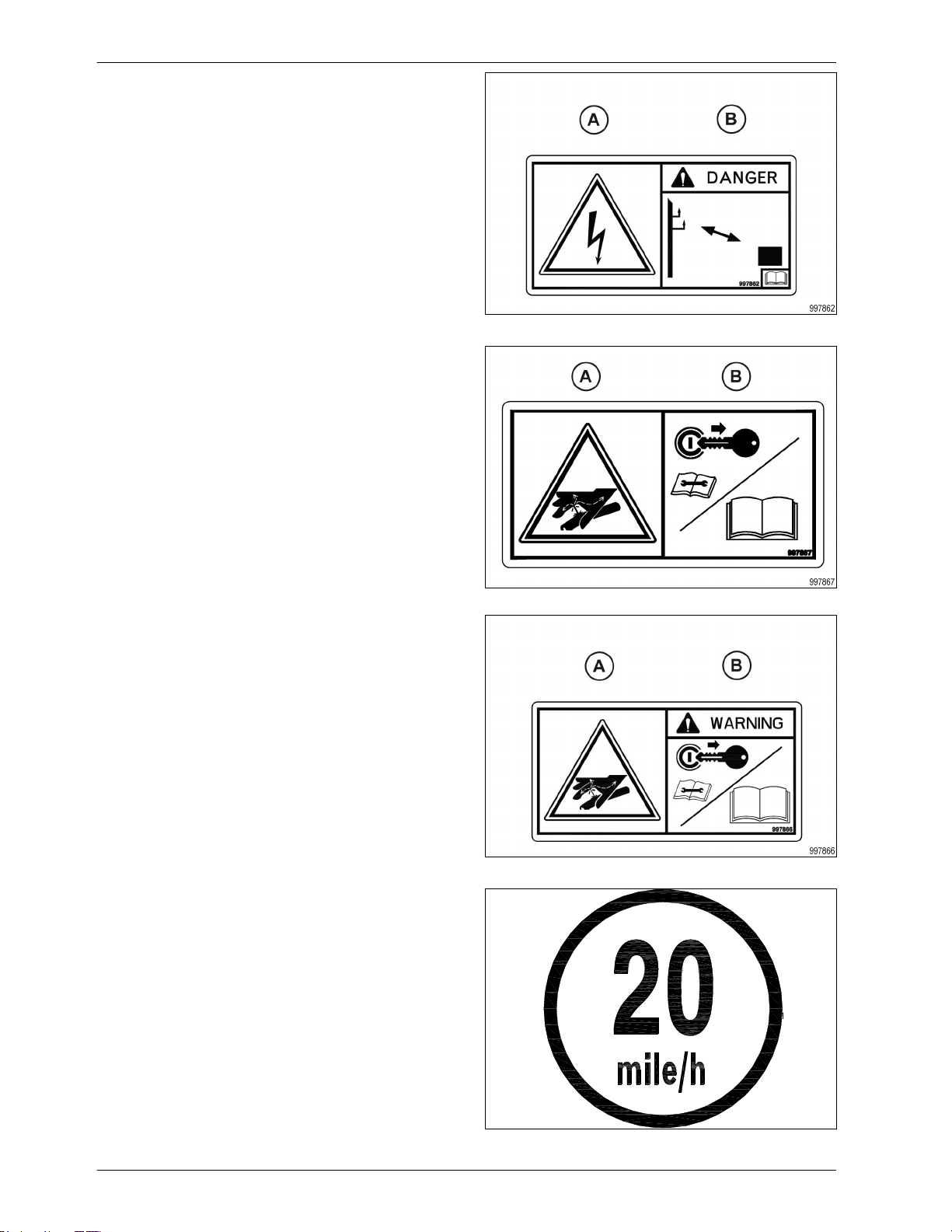
(6) Warning/read operators manual
Hazard (A): General safety alert.
Avoidance (B): Read and understand the
operators manual before operating the machine.
Fig. 31
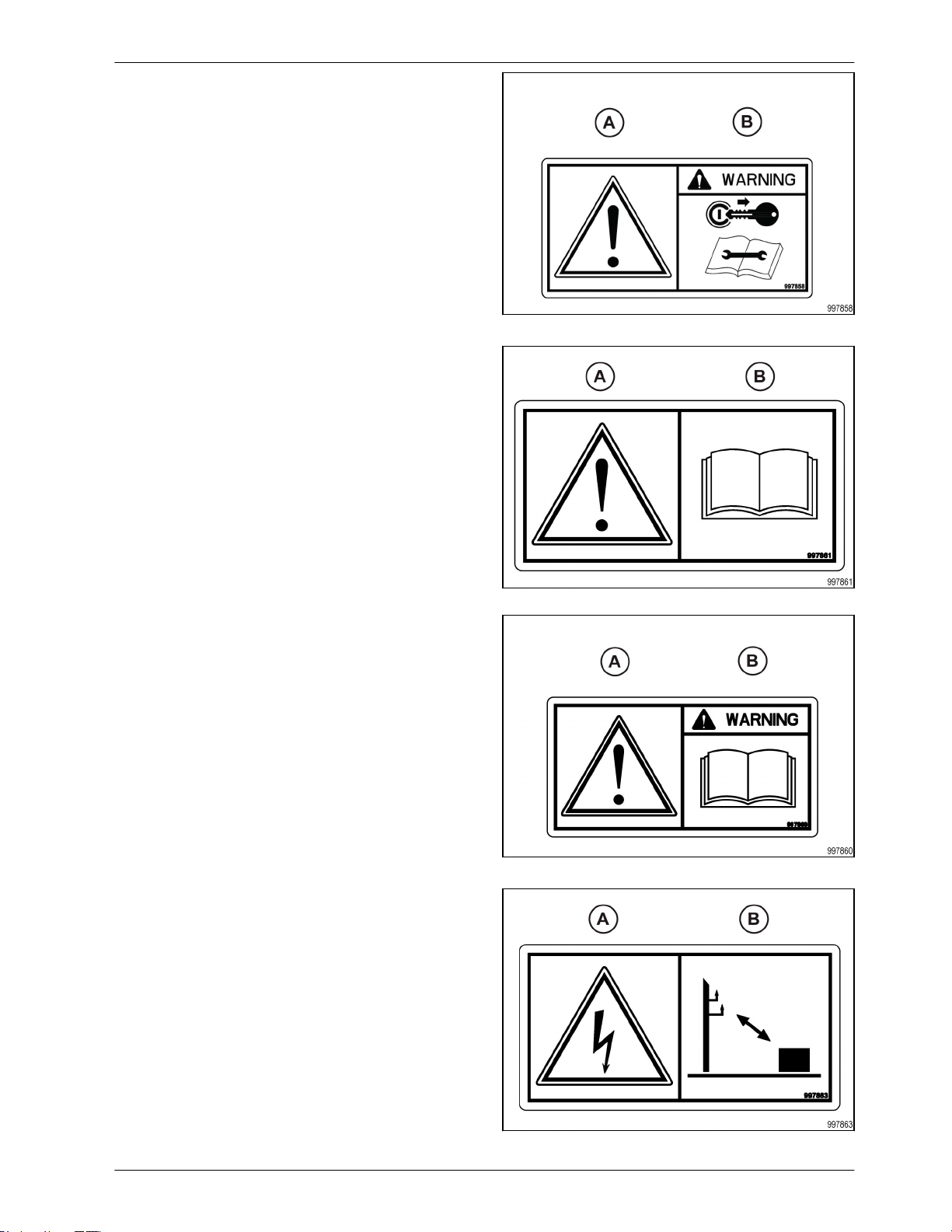
(7) Danger/high line
Hazard (A): Electrical shock hazard - risk of
personal injury and component damage.
Avoidance (B): Keep the correct distance away
from electrical power lines.
Fig. 32
Fig. 32
Fig. 33
Page 27
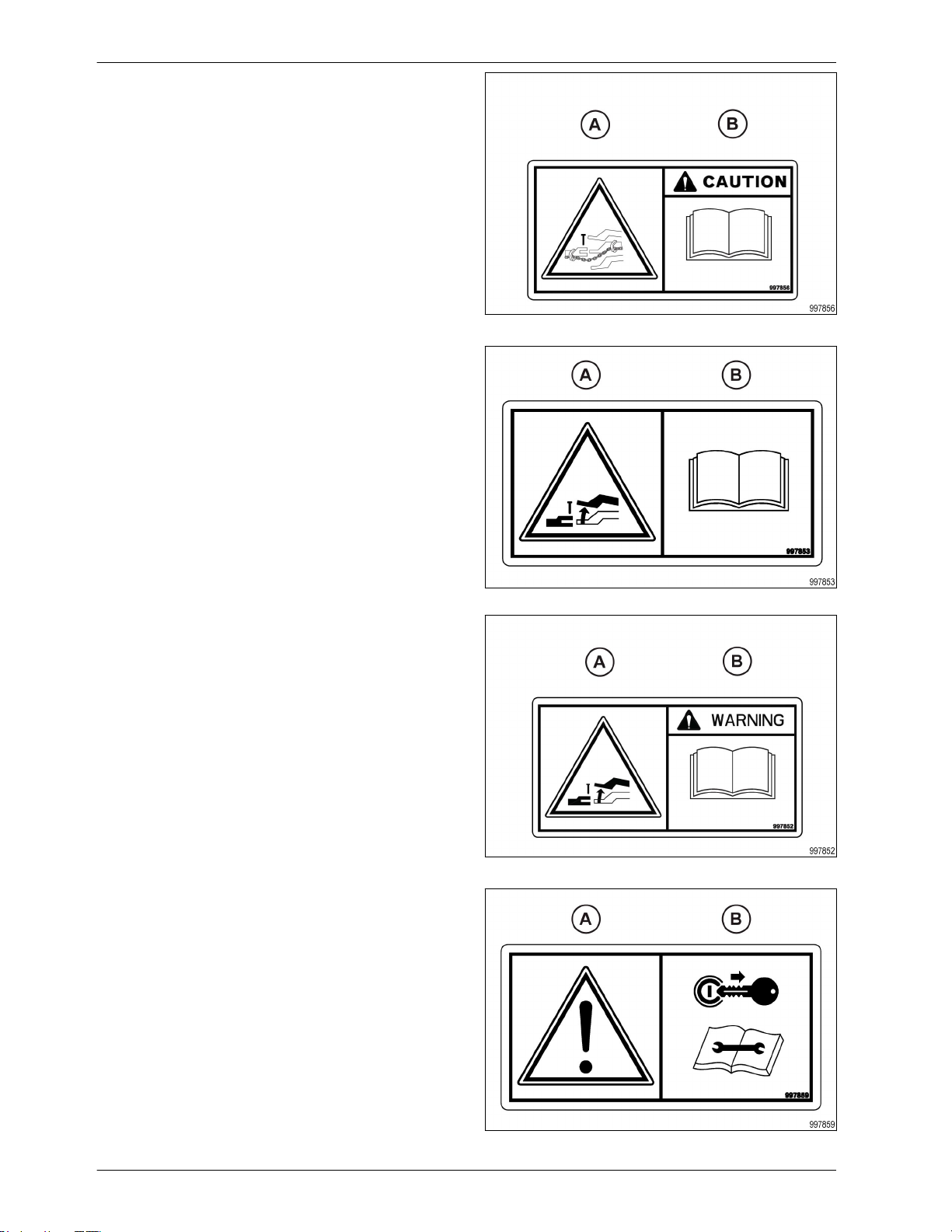
(8) Warning/hydraulic fluid pressure
27
Hazard (A): Injection hazard into skin - escaping
fluid under high pressure.
Avoidance (B): Turn off the engine, remove the
key, relieve the pressure before maintenance or
repair. Refer to the operator manual for the correct
service procedures.
1. Safety
Fig. 33
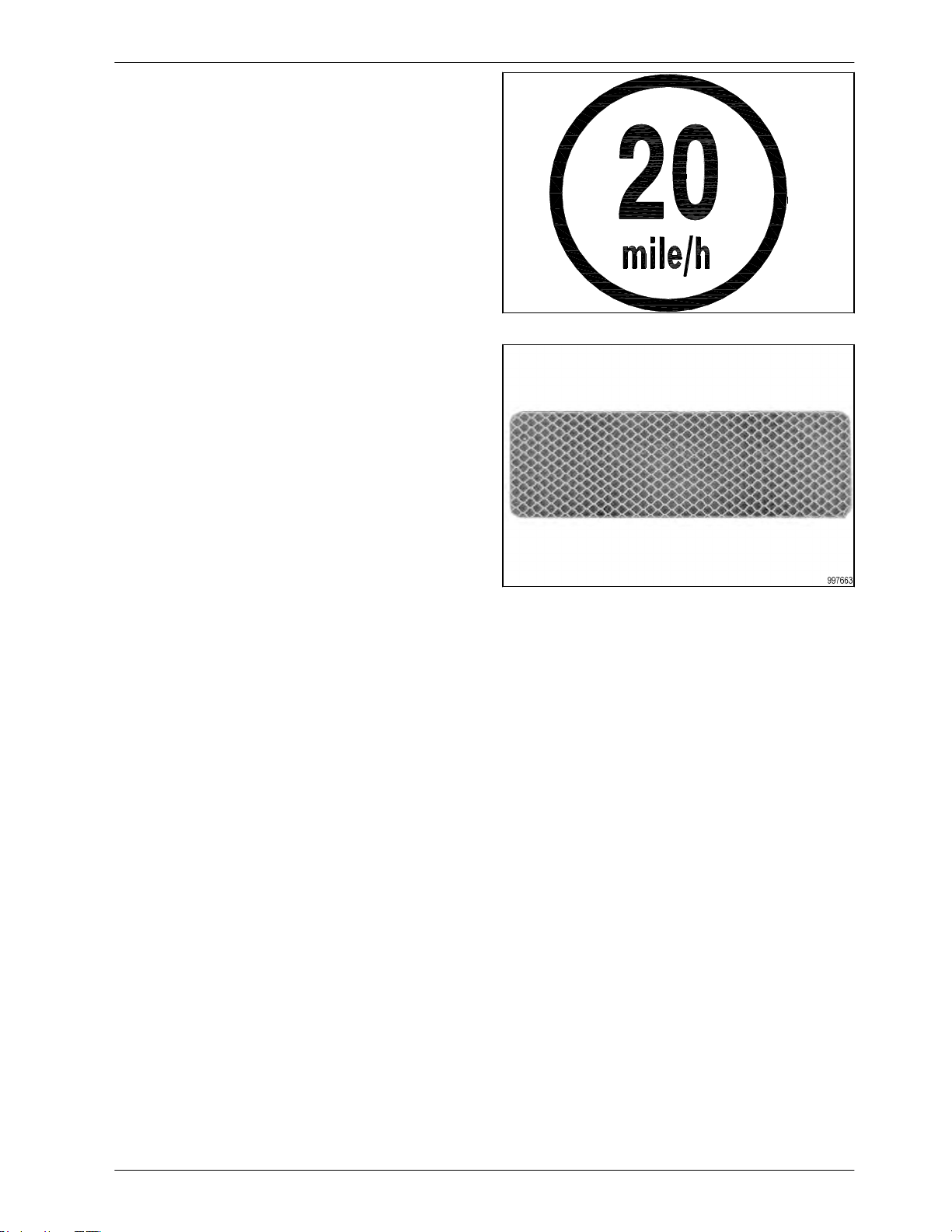
(9) Maximum speed
The maximum speed safety sign displays the
maximum speed to transport the machine.
Fig. 34
Fig. 34
Fig. 35
Page 28
1. Safety
28
(10) Reflector/yellow
Fig. 35
Fig. 36
Page 29

2. Introduction
29
2. Introduction
2.1 Introduction .............................................................28
2.1.1 Units of measurement ..................................................29
2.1.2 Replacement parts .....................................................29
2.1.3 Intended use .........................................................29
2.1.4 Proper disposal of waste ................................................29
2.2 Machine identification ...................................................31
2.2.1 Serial number plate location ..............................................31
2.2.2 Serial number description ................................................31
Page 30

2. Introduction
30
2.1 Introduction
CAUTION:
In some of the illustrations used in this Operator Manual, panels or guards may have been
removed for clarity. Never operate the tractor with these panels and guards removed. If
the removal of a shield is necessary to make a repair, it must be replaced before
operation.
CAUTION:
Read this book in its entirety prior to operating machine. Use only genuine replacement
parts for repairs and/or replacement.
This manual gives the operator the proper instructions needed for operation and maintenance. Read,
understand, and follow these instructions for best machine performance and life. With proper maintenance
and operation procedures, the machine will have better over all performance. Use normally available tools
for maintenance on this machine.
All operators must read and understand this manual before operating this machine. Where possible,
operators who have not operated the machine must receive instruction from an operator who has operated
this machine. Your dealer can give instruction in machine operation. Keep this manual with the machine for
future reference. If the original manual is damaged, order a replacement from your dealer.
See your dealer in for any service problems and adjustments. The dealer is equipped for all service work
and to help with specific applications of the tractor in local conditions.
Left-hand and right-hand are determined by facing the direction the machine will travel when in use.
2.1.1 Units of measurement
Measurements are given in metric units followed by the equivalent in US units. Hardware sizes are given
in millimeters for metric hardware and inches for US hardware.
2.1.2 Replacement parts
To receive prompt efficient service, remember to have the following information:
Correct part description and part number
Model number of the machine
Serial number of the machine
2.1.3 Intended use
This machine is designed solely for use in customary agricultural operations.
Do not use this machine for any application or purpose other than those described in this manual. The
manufacturer accepts no liability for damage or injury resulting from misuse of this machine.
Compliance with the conditions of operation, service and repair as specified by the manufacturer constitute
essential elements for the intended use of this machine.
This machine should be operated, serviced and repaired only by qualified persons familiar with its
characteristics and familiar with the relevant safety rules and procedures.
All generally recognized safety regulations and road traffic regulations must be obeyed at all times.
Any unauthorized modifications performed on this machine will relieve the manufacturer of all liability for
any resulting damage or injury.
2.1.4 Proper disposal of waste
Improper disposal of waste can pollute the environment and ecology. A few examples of potentially
harmful equipment waste can include, but not limited to, items such as oil, fuel, coolant, brake fluid, filters,
battery chemicals, tires, etc.
Page 31

2. Introduction
31
Use leak proof containers when draining fluids. Do not use food or beverage containers to collect waste
fluids, as food or beverage container(s) may mislead someone into drinking from them.
Do not pour or spill waste onto the ground, down a drain, or into any water source.
Air conditioning refrigerants escaping into the air can damage the Earth's atmosphere. Government
regulations may require a certified air conditioning service center to recover and recycle used air
conditioning refrigerants.
Inquire with local environmental or recycling center on the proper way to recycle or dispose waste.
Page 32

2. Introduction
32
2.2 Machine identification
Each machine is identified by a model and a serial number.
Record these numbers in the spaces given.
Give the model number and serial number to your dealer when parts or service are required.
Machine model number:
Machine serial number:
Date of delivery:
Dealer name:
Dealer address:
Dealer telephone number:
Dealer e-mail address:
Dealer fax number:
2.2.1 Serial number plate location
The serial number plate (1) is located on the side
of the main frame tube.
1
2.2.2 Serial number description
Description of the serial number for model year 2010 and up.
Fig. 1
Fig. 2
(1) Beginning symbol
(2) World manufacturer code
(3) Brand code
(4) Model identifier (model number)
(5) Check letter (0 or used if model identifier is
five digits)
(6) Model year code (A=2010, B=2011, C=2012,
and on)
Page 33

2. Introduction
33
(7) Plant code
(8) Family code
(9) Unit number for the year
(10) Ending symbol
Page 34

3. Assembly
34
Assembly ................... .............. ...........................34-35
3.
Mainframe................................................36
Front inner wing anchor/rest............................................37
Front hitch pivot....................................................... 38
Front caster mount.....................................................39
Front caster mount-mainframe..........................................40
Front hitch pivot assembly..............................................41
Front lift cylinders-mainframe............................................42
Front hitch...............................................43
Hydraulic jack.........................................................44
Docking station........................................................45
Rear inner wing anchor/rest 51ft.........................................46
Rear inner wing anchor/rest 61ft.........................................47
Inner wing 51ft..........................................................48
Inner wing 61ft..........................................................49
Outer wings..............................................50
Outer wing fold linkage.................................................51
Outer wing latch........................................................52
Outer wing latch system................................................53
51ft inner wing fold cylinder mounts.....................................54
51ft inner wing fold cylinder rod connection/wing rest.....................55
61ft inner wing fold cylinder mounts......................................56
51ft outer wing fold cylinders ..................................57
61ft outer wing fold cylinders............................................58
Rear axle..............................................................59
Rear hitch.............................................................60
Rear lift cylinders-mainframe............................................61
Lift axle-rear wing.......................................................62
Rear lift cylinder-inner & outer wing ......................................63
Front lift assembly left-inner & outer wing.........................64
Front lift assembly right-inner & outer wing...............................65
Front lift cylinder-inner & outer wing.....................................66
Row unit-frame mount..................................................67
Row unit placement-mainframe.........................................68
Row unit placement-51ft inner wing......................................69
Row unit placement-61ft inner wing......................................70
Row unit placement-51ft outer wing......................................71
Row unit placement-61ft outer wing......................................72
Page 35

3. Assembly
35
3. Assembly-continued
Hose channel-mainframe..................................... 73
Hose channel-inner wing...............................................74
Hose channel-front hitch...............................................75
Down pressure valve...................................................76
Down pressure valve mount.............................................77
Hydraulic hose assembly sequence......................................78
51ft lift hydraulics.............................
..........................79
61ft lift hydraulics.... ............. ............ ............80
51 & 61ft lift hydraulics.. ... ..
........................................81
51ft wing fold hydraulics................................................82
51ft wing fold hydraulics................................................83
61ft wing fold hydraulics................................................84
61ft wing fold hydraulics..................................... ............85
Down pressure hydraulics-DP block......................................86
Down pressure hydraulics-DP block.............................87
Down pressure hydraulics-mainframe.. ... .. ............................88
Down pressure hydraulics-inner wing....................................89
Down pressure hydraulics-outer wing....................................90
Rear hitch hydraulics................................................91-92
Rear hitch hydraulic & electrical fittings..................................93
Front light mount........................................................94
SMV sign & stop collars ......................................95
Rear lights, light module, & lift switch....................................96
Lift switch... . .......................................................97-99
Bleeding air from the hydraulic lift system...............................100
Bleeding air from the hydraulic fold system..............................101
Leveling the mainframe.................................................102
Leveling the wings ..................................................103-104
Model decals-front hitch.....................................105
Model decals-outer wing................................................ 106
Tire air pressure....... ...............................................107
Page 36

MAIN FRAME
36
3. Assembly
COMPOSITE BEARING
BUSHING 2.027 ID X
2.489 OD X 5.50
356900
COMPOSITE BEARING
BUSHING 2.027 ID X
2.489 OD X 7.88 357547
REAR MAIN FRAME
357894
FRONT MAIN FRAME
357890
ADJUST
ANCHOR 357609
NUT 2POSLK
3/4-10NC 5Z 88356
BLT HEX 3/4-10NC
X 2 8YZ 88290
HEADLESS PIN(2)
1X5.12 221344
PIN ROLL 1/4 X 2-1/4 Z
42484
332447
COMPOSITE BEARING
BUSHING 2.527 ID X
2.988 OD X 4.75 357546
WSHR FLAT
1(1-1/16 X 2-1/2ACT)
Z 88196
Page 37

3. Assembly
37
FRONT INNER WING ANCHOR/REST
FRONT WING REST
WELD-51FT ONLY
358622
BLT HEX 5/8-11NC X 3
5Z 88408
WSHR FLAT 5/8(11/16
X 1-3/4ACT) 88277
REST BUMPER
353529
FRONT INNER WING
ANCHOR
332704
NUT TOP LK 1/2-13NC
5Z 88661
BLT HEX 1/2-13NC X 4
5Z 88595
BLT HEX 3/4-10NC
X 2-1/4 8YZ 89433
NUT TOP LK
5/8-11NC 5Z 88845
NUT TOP LK
3/4-10NC 8Z 88665
358622 IS BOLTED ON 51FT MODELS ONLY.
FOR 61FT MODELS THE RUBBER BUMPERS ARE BOLTED ONTO THE
TOP PLATES ON ITEM 332704.
332719
Page 38

FRONT HITCH PIVOT
38
PIN ROLL 3/8DIA X 2-1/2 Z
88770
PIN 1 DIA X 8.88
357522
3. Assembly
WSHR FLAT
1(1-1/16 X 2-1/2ACT)
88196
FRONT HITCH PIVOT
356996
PIN 2.50 DIA X 9.75
357523
COMPOSITE BEARING BUSHING
2.527 ID X 2.988 OD X 9.50
357548
BLT HEX 5/8-11NC X 4
5Z 88298
NUT 2POSLK
5/8-11NC 5Z 88369
332449
Page 39

3. Assembly
39
FRONT CASTER MOUNT
BLT HEX 1-8NC X 3
5Z 88399
NUT 2POSLK 3/4-10NC
5Z 88356
FRONT CASTER MOUNT
356998
TOP TUBE
241563
BLT HEX 3/4-10NC X
5 5Z 88305
BLT HEX 5/8-11NC X
4 5Z 88298
WSHR FLAT
1(1-1/16 X 2-1/2ACT)
88196
NUT 2POSLK
1-8NC 5Z 88348
COMPOSITE BEARING
BUSHING 3.027 ID X
3.487 OD X 5.75
357545
LARGE WEAR PLATE
242932
332451
NUT 2POSLK
5/8-11NC 5Z 88369
PIN 2.50 X
14.50 357524
Page 40

FRONT CASTER MOUNT MAIN FRAME
40
RIGHT MAIN WALKER
333107
FRONT CASTER MOUNT
356998
3. Assembly
LEFT MAIN WALKER
333106
INSIDE WHEEL TO LEAD ON BOTH RIGHT
WALKER & LEFT WALKER
701381
Page 41

3. Assembly
41
FRONT MAIN FRAME
357890
FRONT HITCH PIVOT ASSEMBLY
ADJUST
ANCHOR 357609
PIN COT 3/16DIA X 2 Z
88133
BLT HEX 1/2-13NC X 3-1/4 5Z
88680
HEADLESS
PIN(2) 1X3-7/16
42430
HYD CYL 4-3/4
X 12 (AM-2540)
235968
HITCH ADJUST
SHIM-THICK
358909
FRONT HITCH PIVOT
356996
FRONT CASTER MOUNT
356998
NUT 2POSLK
1/2-13NC 5Z
88363
HITCH ADJUST SHIM
357610
HEADLESS PIN
1X5.12 221344
PIN ROLL 1/4 X
2-1/4 42484
WSHR FLAT
1(1-1/16 X
2-1/2ACT) 88196
701117
Page 42

FRONT LIFT CYLINDERS-MAINFRAME
42
3/4IN CYLINDER STOP (YELLOW)
241647 QTY2
1-7/16 IN CYLINDER STOP (BLUE)
244586 QTY2
1-1/2IN CYLINDER STOP (GRAY)
241649 QTY4
3. Assembly
TRANSPORT CHANNEL
358289
HYD CYL 4-3/4 X 12 (AM-2540)
235968
ADJUST ANCHOR
357609
701364
Page 43

3. Assembly
43
NUT TOP LK 1-8NC 5Z
88658
FRONT HITCH
FRONT CASTER MOUNT
356998
BLT HEX 1-8NC X
3 5Z 88399
JACK LEG WELD
239727
JACK TUBE WELD
239728
MAIN HITCH
240469
NUT TOP LK
5/8-11NC 5Z 88845
HITCH BOLT 1-1/4 X 7
UNC X 7.00 LONG
354313
BLT-U 5/8-11NC X 4 X 5-1/2
Z 45633
NUT JAM 1-1/4-7NC 5Z
88622
CAST DUAL
HITCH 18236
332450
Page 44

HYDRAULIC JACK
44
3. Assembly
PIN ROLL 1/4 X 2-1/4 Z
42484
HEADLESS PIN(2) 1X4.00
221714
ELB 6MJ X 6MORB
61239
HSE 3KPSI 1/4X120 6FJX-6FJX
238617
JACK TUBE
239728
PIN,CLICK 7/16X1-1/2
32990
HITCH PIN 1-1/8X4-3/4
23011
QUICK COUPLER 8 ORB
247425
JACK LEG
239727
ADP 6 MJ X 8 MORB
58543
HYD CYL, 3X24 FGS #A519CY10
51241F
Page 45

3. Assembly
45
WSHR FLAT 1/4(5/16 X 3/4ACT) Z
88261
NUT TOP LK 1/4-20NC 5Z
89501
DOCKING STATION
BLT HEX 1/4-20NC X
3/4 5Z 88993
STORAGE TUBE-OWNERS
MANUAL 234313
PLUG HOLDER
223329
BLT HEX 1/4-20NC X 1 5Z
88203
BLT HEX 1/4-20NC X 1-1/2 5Z
88504
DS COLLAR
322417
DS HOSE CRADLE
322412
NUT HEX 3/8-16NC 5Z
88103
NUT 2POSLK 1/4-20NC 5Z
88237
DOCKING STATION
322425
U-BOLT .375 X 5.125 X
8.063 X 5.125
A64244
WSHR HLK 3/8ID Z
88362
332426
Page 46

REAR INNER WING ANCHOR/REST 51FT
46
INNER WING ANCHORREAR MF 51FT 358603
1/2X6-1/2 HITCH PIN W/
HAIRPIN 350876
3. Assembly
BLT HEX 3/4-10NC X 2-1/4
8YZ 89433
REAR MAIN FRAME
357894
NUT TOP LK
3/4-10NC 8Z 88665
332452
Page 47

3. Assembly
47
1/2X6-1/2 HITCH
PIN W/HAIR PIN
350876
REAR INNER WING ANCHOR/REST 61FT
INNER WING
ANCHOR-REAR
MF 61FT 358246
NUT TOP LK
3/4-10NC 8Z 88665
REAR MAIN FRAME
357894
BLT HEX 3/4-10NC
X 2-1/4 8YZ 89433
332778
Page 48

INNER WING 51FT
48
3. Assembly
LIFT CYLINDER PIN
1" DIA X 7.63 357531
PIN ROLL
3/8DIA X 2-1/2 Z
88770
COMPOSITE BEARING
BUSHING 2.027 ID X
2.489 OD X 6.75 357551
NUT 2POSLK
5/8-11NC
88369
REAR LIFT
ANCHOR 358378
WSHR FLAT
1(1-1/16 X
2-1/2ACT)
88196
BLT HEX 5/8-11NC X 2 5Z
88294
NUT 2POSLK
5/8-11NC
88369
STUB WELDINNER WING
BRACE 358602
COMPOSITE BEARING
BUSHING 1.277 ID X
1.742 OD X 4.06 357560
BLT HEX
5/8-11NC X 2
88294
INNER WING BRACE-51FT
358610
BACK PLATECROSS BRACE
358663
BLT HEX
5/8-11NC X 4
88298
LIFT CYLINDER PIN
1" DIA X 8.88 357522
NUT JAM
1-1/4-7NC 88622
COMPOSITE BEARING
BUSHING 1.527 ID X
2.240 OD X 7.44
355388
51FT RIGHT INNER
WING - REAR
358373
51FT LEFT INNER
WING - REAR
358371
BLT-U 5/8-11NC
X 4 X 7-1/4 Z
89097
NUT 2POSLK
3/4-10NC 5Z
88356
BLT HEX 3/4-10NC X
2 8YZ 88290
PIN 2 X 10.88
358276
NUT 2POSLK
5/8-11NC
88369
51FT LEFT INNER
WING - FRONT
358372
51FT RIGHT INNER
WING - FRONT
358374
BLT HEX
5/8-11NC X
3-1/2 5Z
88292
CYLINDER
ADJUST ROD
69567
BLT HEX
3/8-16NC X
2-3/4 5Z
88582
NUT TOP LK
3/8-16NC 5Z 88659
PIVOT PIN (1-1/2 X 10)
235801
332787
Page 49

3. Assembly
49
STUB WELDINNER WING
BRACE 358602
INNER WING 61FT
ALL COMPONENTS THE SAME AS PAGE
30 EXCEPT AS NOTED
INNER WING BRACE-61FT
358395
61FT LEFT INNER
WING - REAR
358228
61FT RIGHT INNER
WING - REAR
358248
STUB WELD-LH
FRONT 358642
STUB WELDRH FRONT
358643
61FT LEFT INNER
WING - FRONT
357884
61FT RIGHT INNER
WING - FRONT
358227
332784
Page 50

OUTER WINGS
50
PIN ROLL
3/8DIA X 2-1/2 Z
88770
WSHR FLAT
1(1-1/16 X
2-1/2ACT)
88196
REAR LIFT
ANCHOR 358378
BLT HEX 5/8-11NC
X2 8829488294
3. Assembly
COMPOSITE BEARING
BUSHING 2.027 ID X
2.489 OD X 6.75 357551
LIFT CYLINDER PIN
1" DIA X 7.63 357531
NUT TOP LK
3/8-16NC 5Z
88659
NUT 2POSLK
5/8-11NC
88369
BLT HEX 3/8-16NC
X 2-1/2 5Z
89012
1-1/4 DIA X 7.38 HINGE
PIN-OUTER WING
358616
51FT LEFT OUTER WINGREAR 358360(SHOWN)
51FT RIGHT OUTER WINGREAR 358361
61FT LEFT OUTER WINGREAR 358234
61FT RIGHT OUTER WINGREAR 358235
LIFT CYLINDER PIN
1" DIA X 8.88 357522
PIN ROLL 3/8DIA X
2-1/2 Z 88770
BLT HEX
3/8-16NC X
2-3/4 5Z 88582
COMPOSITE BEARING
BUSHING 1.527 ID X
2.240 OD X 7.44
355388
NUT JAM
1-1/4-7NC 88622
WSHR FLAT
1(1-1/16 X
2-1/2ACT)
88196
NUT 2POSLK
3/4-10NC 5Z
88356
BLT HEX 3/4-10NC
X 2 8YZ 88290
51FT LEFT OUTER WINGFRONT 358358(SHOWN)
51FT RIGHT OUTER
WING-FRONT 358359
61FT LEFT OUTER WINGFRONT 358225
61FT RIGHT OUTER
WING-FRONT 358226
332796
PIVOT PIN (1-1/2 X 10)
235801
CYLINDER
ADJUST ROD
69567
NUT TOP LK
3/8-16NC 5Z
88659
Page 51

3. Assembly
51
NUT 2POSLK 1-1/4-7NC
5Z 88430 51FT
NUT TOP LK 1-1/2-6NC 5Z
89126 61FT
OUTER WING FOLD LINKAGE
51FT BANNANA ARM
ASSEMBLY-OUTER WING
359424
51FT BANNANA ARM
WELD-OUTER WING
359419
WSHR FLAT 1-1/4(1-3/8 X
3ACT) Z 88602 51FT ONLY
WSHR FLAT 1-1/2(1-5/8 X
3-1/2) Z 88616 61FT ONLY
BLT HEX 1-1/4-7NC X 7
5Z 89134 51FT ONLY
BLT HEX 1-1/2-6NC X
7-1/2 5Z 89124 61FT
ONLY
NUT 2POSLK 1-1/4-7NC
5Z 88430
BLT HEX 1-1/4-7NC X 7
5Z 89134
701384A
51FT OUTER WING FOLD
LINK ASSEMBLY 1-1/2
DIA 359425
61FT OUTER WING FOLD
LINK 1-1/2 DIA 359423
Page 52

OUTER WING LATCH
52
3. Assembly
PIVOT TUBE-LATCH
358687
NUT 2POSLK 3/4-10NC 5Z
88356
BLT HEX 3/4-10NC X 5 5Z
88305
WSHR FLAT 3/4(13/16 X
2ACT) 88131
LATCH WELDMENT
358277
SPRING,EXT 30-COILS
1.5-OD 9.5-LONG
25863
BLT HEX 3/8-16NC X 2-1/2 5Z
89012
PIN BUSHING
359427
NUT TOP LK
3/8-16NC 5Z
88659
LOCK PIN-OUTER WING
(ZP) 359426
701384B
Page 53

3. Assembly
53
(1) Latch
(2) Latch pin
(3) Spring
(4) Latch stop
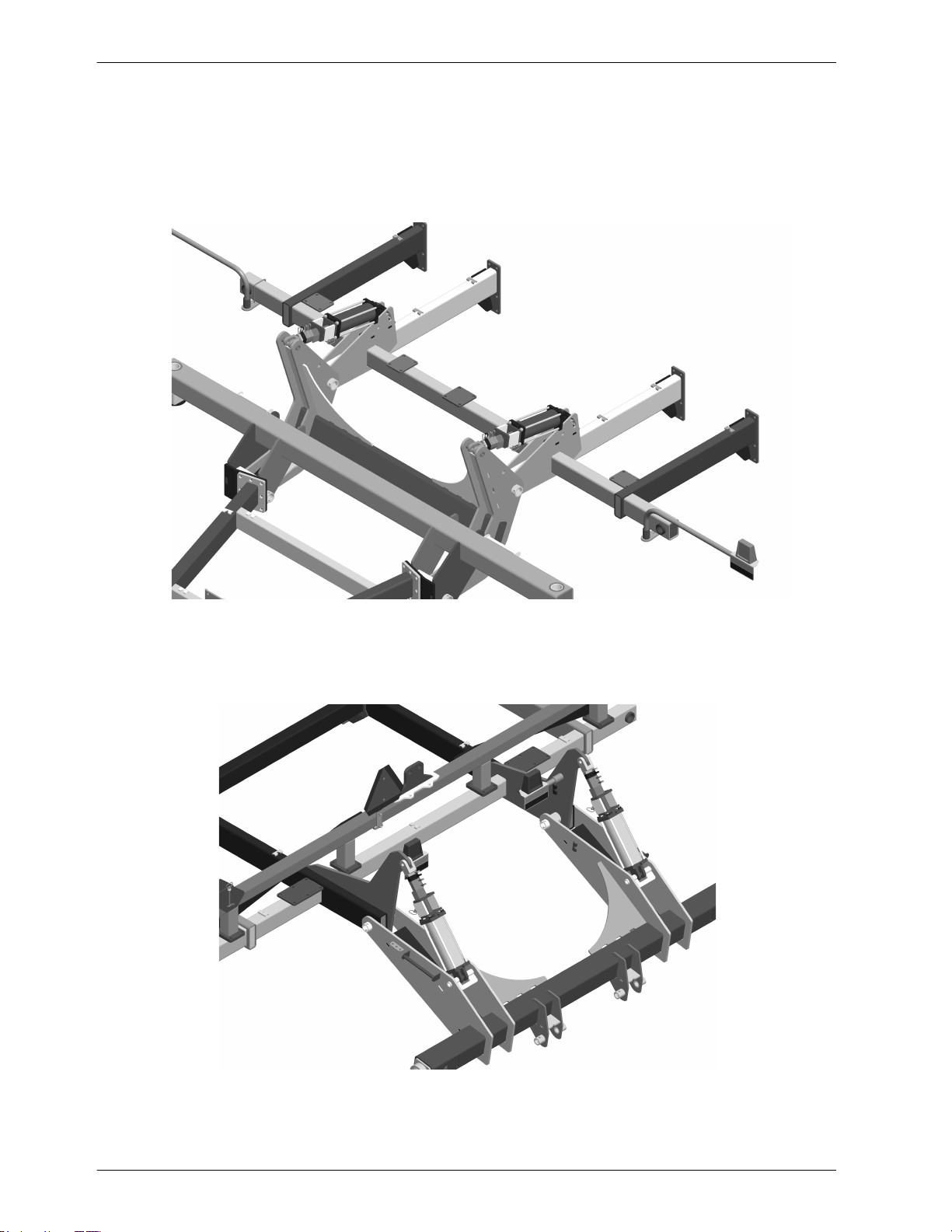
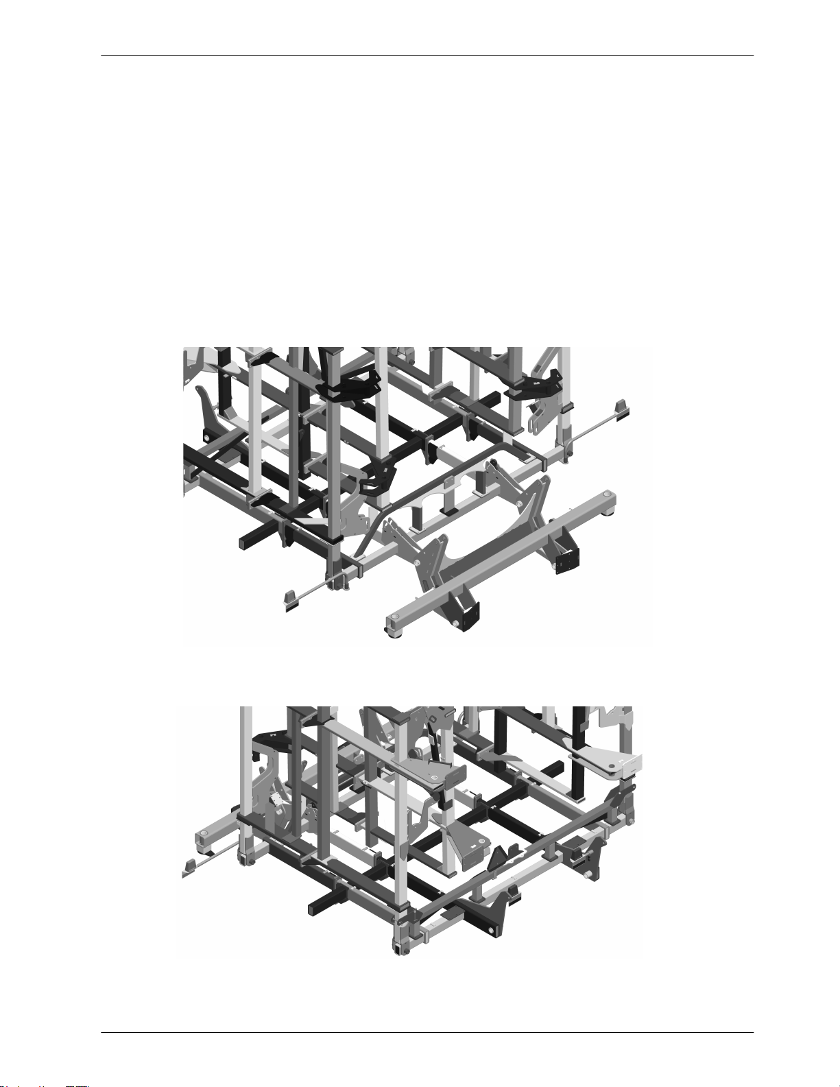
Figure 1 shows the latch system with the outer wing
unfolded. Make sure items 1 thru 4 are bolted tightly
and secured before folding and unfolding the outer
wing. The purpose of the latch system is to
make sure the outer wing folds and
unfolds smoothly without any abrupt changes in
the folding speed during the fold process.
OUTER WING LATCH SYSTEM
1
2
3
figure 1
4
Figure 2 shows the outer wing and latch
system in the folded position.
figure 2
Page 54

51FT INNER WING FOLD CYLINDERS
54
PIN ROLL 1/4 X 2-1/4 Z
42484
3. Assembly
HEADLESS PIN 1-1/4X3-3/4
42431
HYD FOLD CYL, 5 X 48
357897
HYD FOLD CYL, 5 X 48
357897
PORTS TO FACE THE
REAR
REAR INNER WING FOLD
CYLINDER - PORTS TO
FACE THE REAR
701116
Page 55

3. Assembly
55
51FT WING REST
HYD FOLD CYL, 5 X 48
357897
51FT INNER WING FOLD CYL CONNECTION
HYD FOLD CYL, 5 X 48
357897
BLT HEX 1-1/4-7NC X 7 5Z
89134
WSHR FLAT 1-1/4(1-3/8 X
3ACT) 88602
NUT 2POSLK 5/8-11NC 5Z
88369
NUT 2POSLK 1-1/4-7NC 5Z
88430
26.00"
701383
BLT-U 5/8-11NC X 4 X 7-1/4
89097
WING REST WELDOUTER WING 51FT
358618
Page 56

61FT INNER WING FOLD CYLINDERS
56
PIN ROLL 1/4 X 2-1/4 Z
42484
HEADLESS PIN 1-1/4X3-3/4
42431
NUT 2POSLK 1-1/4-7NC 5Z
88430
3. Assembly
WSHR FLAT 1-1/4(1-3/8 X
3ACT) 88602
BLT HEX 1-1/4-7NC X 7 5Z
89134
HYD FOLD CYL, 5 X 48
357897
HYD FOLD CYL, 5 X 48
357897
PORTS TO FACE THE
REAR
REAR INNER WING FOLD
CYLINDER - PORTS TO
FACE THE REAR
701403
Page 57

3. Assembly
57
PIN ROLL 1/4 X 2-1/4 Z
42484
51FT OUTER WING FOLD CYLINDERS
HYD FOLD CYL, 5X36
247829
HEADLESS PIN 1-1/4X3-3/4
42431
701384C
Page 58

61FT OUTER WING FOLD CYLINDERS
58
REAR INNER WING FOLD
CYLINDER - PORTS TO
FACE THE REAR
HYD FOLD CYL, 5 X 48
357897
3. Assembly
HEADLESS PIN 1-1/4X3-3/4
42431
WING REST-OUTER WING
358272
WING REST MOUNTS
4.00" FROM END OF
4SQ TUBE TO
MOUNTING PLATE
PIN ROLL 1/4 X 2-1/4
42484
NUT 2POSLK 5/8-11NC 5Z
88369
BLT-U 5/8-11NC X 4 X 5-1/2
45633
HEADLESS PIN 1-1/2X3-3/4
359432
HYD FOLD CYLINDER 6X36
359392
701394
Page 59

3. Assembly
59
PIN ROLL
3/8DIA X 2-1/2
88770
REAR AXLE
BLT HEX 5/8-11NC X 3-1/2 5Z
88292
NUT TOP LK 5/8-11NC 5Z
88845
MAIN REAR PIVOT PIN 2 DIA
X 12.75 357071
NUT TOP LK
5/8-11NC 5Z 88845
REAR LIFT WHEEL CYL
PIN 1 DIA X 11.50 357521
ASSY-HUB/
SPINDLE A37309
BLT HEX 5/8-11NC X
3-1/2 5Z 88292
NUT TOP LK
5/8-11NC 5Z 88845
BLT HEX 5/8-11NC X
3-1/2 5Z 88292
REAR PIVOT PIN 1.50 DIA
X 10.75
357520
REAR MAIN AXLE-FIRESTONE
358958
NUT TOP LK
3/4-10NC 8Z 88665
BLT HEX 3/4-10NC X
6-1/2 8YZ 88600
332454
Page 60

REAR HITCH
60
REAR HITCH 358252
COMPOSITE BEARING
BUSHING 1.527 ID X
2.240 OD X 4.00 358295
3. Assembly
BLT HEX 3/4-10NC X 6
5Z 88293
BLT HEX
7/8-9NC X 3
8YZ 88468
SWIVEL PINTLE
HOOK 358307
NUT 2POSLK
7/8-9NC 5Z 88836
BLT HEX 5/8-11NC
X 3-1/2 5Z 88292
PIVOT PIN 1.50
DIA X 8.75 358308
REAR HITCH
BRACE TUBE
358258
NUT TOP LK
5/8-11NC 5Z
88845
REAR MAIN AXLEFIRESTONE 358958
PLATE-HITCH
SUPPORT(61FT
ONLY)358299
INNER WING
ANCHOR-61FT
358246
NUT TOP LK
3/4-10NC 8Z 88665
COMPOSITE BEARING
BUSHING 1.527 ID X
2.240 OD X 5.00 357558
COMPOSITE BEARING
BUSHING 1.527 ID X
2.240 OD X 4.00 358295
PIVOT PIN 1.50
DIA X 8.75 358308
BLT HEX 5/8-11NC
X 3-1/2 5Z 88292
332799
REAR HITCH
BRACKET 358256
NUT TOP LK
5/8-11NC 5Z
88845
REAR MAIN FRAME
357894
BLT-U 5/8-11NC
X 6 X 5-1/2 Z
89093
NUT-TOPLOCK
FLANGE .63 NC GR8 ZP
89505
Page 61

3. Assembly
61
REAR LIFT CYLINDERS-MAINFRAME
3/4IN CYLINDER STOP (YELLOW)
241647 QTY2
1-7/16 IN CYLINDER STOP (BLUE)
244586 QTY2
1-1/2IN CYLINDER STOP (GRAY)
241649 QTY4
TRANSPORT CHANNEL
358289
HYD CYL 5 X 12
235967
701363
Page 62

REAR WING AXLE
62
BLT HEX 5/8-11NC X 3-1/2
5Z 88292
3. Assembly
REAR PIVOT PIN 2 DIA X 11.88
357519
OUTER WING WHEEL PIVOT
356857
NUT 2POSLK 1/2-13NC
5Z 88363
NUT 2POSLK
5/8-11NC 5Z 88369
PIN ROLL
3/8DIA X 2-1/2 Z
88770
REAR LIFT
CYLINDER PIN 1 DIA
X 9.75 357525
HUB & 2 IN SPINDLE ASSY
14131
BLT HEX 1/2-13NC
X 3-1/4 5Z 88680
333114
Page 63

3. Assembly
63
REAR LIFT CYLINDER-INNER & OUTER WING
4 X 12 HYD LIFT CYLINDER
358314 INNER WING
3-3/4 X 12 HYD LIFT CYLINDER
358313 OUTER WING
701362
Page 64

FRONT LIFT ASSEMBLY LEFT-WING
64
3. Assembly
BOTTOM LIFT ARM
356853
COMPOSITE BEARING
BUSHING 1.527 ID X 2.240
OD X 5.94 357557
NUT 2POSLK
3/4-10NC 5Z 88356
HEADLESS PIN
1-1/2 X 9-19/32
54595
TOP FRONT LINK ARM
356852
COMPOSITE BEARING
BUSHING 1.527 ID X
2.240 OD X 7.44 355388
BLT HEX
3/4-10NC X 4
5Z 88272
COLLAR
16009
BLT HEX
3/8-16NC X 2-3/4
5Z 88582
NUT TOP LK
3/8-16NC 5Z
88659
NUT TOP LK
3/8-16NC 5Z
88659
BLT HEX
3/8-16NC X
2-3/4 5Z 88582
GAUGE WHEEL
VERTICAL MOUNT
355380
INSIDE WHEEL TO LEAD
HEADLESS PIN
1-
1/2 X 9-19/32
54595
COMPOSITE BEARING
BUSHING 2.560 ID X
2.988 OD X 7.69 355390
COMPOSITE BEARING
BUSHING 1.527 ID X
2.240 OD X 7.44
355388
333111
ASSY - LEFT WING WALKER
333109
Page 65

3. Assembly
65
FRONT LIFT ASSEMBLY RIGHT-WING
ALL COMPONENTS THE SAME AS PAGE
46 EXCEPT AS NOTED
ASSY - RIGHT WING WALKER
333110
INSIDE WHEEL TO LEAD
333112
Page 66

FRONT LIFT CYLINDER-INNER & OUTER WING
66
3. Assembly
HYD LIFT CYL 4-1/2 X 12
235969
INNER WING
HYD LIFT CYL 3-1/2 X 12
358312
OUTER WING
701361
Page 67

3. Assembly
67
ROW UNIT-FRAME MOUNT
CAST CORNER CAP
240694
BLT HEX 3/4-10NC X 2-1/2 8YZ
89389
BASE SHANK ASSEMBLY(ROW UNIT)
357582
NUT 2POSLK 3/4-10NC 5Z
88356
701382A
Page 68

ROW UNIT PLACEMENT-MAINFRAME
68
3. Assembly
30.00
32.5030.00
60.00 60.00
7.86
30.0030.00
60.00 60.00
90.00
90.0090.00
701382
Page 69

3. Assembly
69
ROW UNIT PLACEMENT-51FT INNER WING
2.52
2.46
30.00
60.00
90.00
30.00
60.00
90.00
Page 70

ROW UNIT PLACEMENT-61FT INNER WING
70
3. Assembly
2.52
2.47
30.00
60.00
90.00
30.00
60.00
90.00
120.00
701388
Page 71

3. Assembly
71
ROW UNIT PLACEMENT-51FT OUTER WING
3.00
2.99
30.00
60.00
30.00
60.00
701389
Page 72

ROW UNIT PLACEMENT-61FT OUTER WING
72
3. Assembly
2.96
3.03
30.00
60.00
90.00
120.00
30.00
60.00
90.00
701390
Page 73

3. Assembly
73
HOSE CHANNEL-MAINFRAME
NUT HEX 3/8-16NC 5Z
88103
WSHR FLAT 3/8(7/16 X 1ACT)
88282
FORMED CHANNELCOVER-MF END 29.25"
358664
FORMED CHANNELCOVER MF 81.00"
358662
FORMED CHANNELMF 81.00"
358658
BLT CRG 3/8-16NC X 6
5Z 89494
NUT HEX 1/4-20NC
5Z 88172
WSHR HLK 1/4ID(5/16ACT)
88262
FORMED CHANNELMF 31.00"
358661
BLT CRG 1/4-20NC X
3/4 SHT NK 5Z
88994
FORMED CHANNELMAINFRAME MIDDLE 75.00"
358659
FORMED CHANNELCOVER MF MIDDLE 103.06"
358663
FORMED CHANNELMF 31.00"
358661
701391
Page 74

HOSE CHANNEL-INNER WING
74
NUT HEX 3/8-16NC 5Z
88103
BLT CRG 3/8-16NC X 6
5Z 89494
WSHR FLAT 3/8(7/16 X 1ACT)
88282
3. Assembly
FORMED CHANNELCOVER INNER WING 107.50"
358655
FORMED CHANNELINNER WING 107.50"
358654
701392
Page 75

3. Assembly
75
HOSE CHANNEL-FRONT HITCH
NUT HEX 3/8-16NC 5Z
88103
WSHR FLAT 3/8(7/16 X 1ACT)
88282
FORMED CHANNELCOVER FRONT HITCH 88.00"
358657
FORMED CHANNELFRONT HITCH 88.00"
358656
BLT CRG 3/8-16NC X 6
5Z 89494
701395
BLT CRG 3/8-16NC X 1 (88467) 5Z
89009
Page 76

DOWN PRESSURE VALVE
76
3. Assembly
LEFT CYLINDER EXTEND
LEFT CYLINDER RETRACT
LEFT SIDE VIEW
FRONT VIEW
RIGHT CYLINDER EXTEND
RIGHT CYLINDER RETRACT
RIGHT SIDE VIEW
PRESSURE TRANSDUCER
LOCATION
DOWN PRESSURE
TRACTOR EXTEND
BOTTOM VIEW
DOWN PRESSURE
TRACTOR RETRACT
358905
Page 77

3. Assembly
77
TRANSDUCER-PRESSURE 0-3000 4MB
A35598
DOWN PRESSURE VALVE MOUNT
ELB10MB-8MJ-90
A35598
DOWN PRESSURE REGEN VALVE
PS-00505-VVA-01
A35598
BLT HEX 3/8-16NC X 1 5Z
89034
NUT 2POSLK 5/8-11NC 5Z
88369
WSHR HLK 3/8ID
88362
FORMED PLATE-DP
COVER 358907
VALVE
FORMED PLATE-DP VALVE MOUNT
358908
BLT-U 5/8-11NC X 4 X 7-1/4
89097
701393
Page 78

HYDRAULIC HOSE ASSEMBLY SEQUENCE
78
3. Assembly
1) BOTTOM - HYDRAULIC FOLD HOSES
2) LIFT HYDRAULIC HOSES
3) DOWN PRESSURE HYDRAULIC HOSES
4) ELECTRICAL HARNESSES-DOWN PRESSURE & LIGHTS
5) TOP - HYDRAULIC HOSES - FRONT PULL HITCH TO REAR HITCH
DISCONNECT
Page 79

3. Assembly
79
51FT LIFT HYDRAULICS
Page 80

61FT LIFT HYDRAULICS
80
3. Assembly
Page 81

3. Assembly
81
LIFT CYLINDER HYDRAULICS - 51'
ITEM PART NO. QTY DESCRIPTION
51 & 61FT LIFT HYDRAULICS
1 235968 2
2 235969 4
3 358312 2
4 358313 2
5 358314 4
6 235967 2
7 247425 2
8 24024 2
9 25591 1
10 13238 2
11 25580 24
12 241494 2
13 240609 1
14 247432 1
15 247431 4
17 240604 2
18 247432 2
19 234947 3
20 235386 1
HYD CYL 4-3/4 X 12 (AM-2540)
HYD CYL 4-1/2 X 12 (AM-2546)
3-1/2 X 12 HYD CYLINDER ASSEMBLY
3-3/4 X 12 HYD CYLINDER ASSEMBLY
4 X 12 HYD CYLINDER ASSEMBLY
HYD CYL 5 X 12 (AM-2534)
QUICK COUPLER 8 ORB
ADP 8MORB X 8MJ
ELB 8MJ X 8FJX
TEE 8MJ X 8MJ X 8MJ
ELB 8MORB X 8MJ
HSE 3KPSI 1/2X276 8FJX-8FJX
HSE 3KPSI 3/8X324 8FJX-8FJX
HSE 3KPSI 3/8X400 8FJX-8FJX
HSE 3KPSI 3/8X232 8FJX-8FJX
HSE 3KPSI 3/8X300 8FJX-8FJX
HSE 3KPSI 3/8X400 8FJX-8FJX
HSE 3KPSI 3/8X194 8FJX-8FJX
HSE 3KPSI 3/8X137 8FJX-8FJX
LIFT CYLINDER HYDRAULICS - 61'
ITEM PART NO. QTY DESCRIPTION
1 235968 2
2 235969 2
3 358312 2
4 358313 2
5 358314 2
6 235967 2
7 247425 2
8 24024 2
9 25591 1
10 13238 2
11 25580 24
12 241494 2
13 240611 1
14 247427 1
15 247431 2
16 67576 2
17 240604 5
18 238618 2
19 234947 2
20 235386 1
HYD CYL 4-3/4 X 12 (AM-2540)
HYD CYL 4-1/2 X 12 (AM-2546)
3-1/2 X 12 HYD CYLINDER ASSEMBLY
3-3/4 X 12 HYD CYLINDER ASSEMBLY
4 X 12 HYD CYLINDER ASSEMBLY
HYD CYL 5 X 12 (AM-2534)
QUICK COUPLER 8 ORB
ADP 8MORB X 8MJ
ELB 8MJ X 8FJX
TEE 8MJ X 8MJ X 8MJ
ELB 8MORB X 8MJ
HSE 3KPSI 1/2X276 8FJX-8FJX
HSE 3KPSI 3/8X324 8FJX-8FJX
HSE 3KPSI 3/8X440 8FJX-8FJX
HSE 3KPSI 3/8X232 8FJX-8FJX
HSE 3KPSI 3/8X276 8FJX-8FJX
HSE 3KPSI 3/8X300 8FJX-8FJX
HSE 3KPSI 3/8X420 8FJX-8FJX
HSE 3KPSI 3/8X194 8FJX-8FJX
HSE 3KPSI 3/8X137 8FJX-8FJX
Page 82

51FT WING FOLD HYDRAULICS
82
3. Assembly
REAR INNER WING FOLD
CYLINDERS PORTS TO FACE THE
REAR
Page 83

3. Assembly
83
ITEM PART NO. QTY DESCRIPTION
51FT WING FOLD HYDRAULICS
1 357897 4
2 247829 4
3 247425 2
4 24024 10
5 A63015 4
6 69080 4
7 13238 2
8 15910 4
9 A65901 16
10 358980 8
11 241494 2
12 25603 3
13 235386 2
14 59909 1
15 25597 4
16 13482 7
17 238204 2
18 67634 1
HYD CYL, 5 X 48 (PRINCE B500480ACDDA07B) HYD
CYL, 5X36 TIE ROD (PRINCE)
QUICK COUPLER 8 ORB
ADP 8MORB X 8MJ
TEE 8MJ X 8FJX X 8MJ
TEE 8MJ X 8MJ X 8FJX
TEE 8MJ X 8MJ X 8MJ
CROSS 8MJ X 8MJ X 8MJ X 8MJ
ELB10MB-8MJ-90 (354405)
RSTR ADP 8FJ-8MJ .075
HSE 3KPSI 1/2X276 8FJX-8FJX
HSE 3KPSI 3/8X75 8FJX-8FJX
HSE 3KPSI 3/8X137 8FJX-8FJX
HSE 3KPSI 3/8X168 8FJX-8FJX
HSE 3KPSI 3/8X40 8FJX-8FJX
HSE 3KPSI 3/8X108 8FJX-8FJX
HSE 3KPSI 3/8X210 8FJX-8FJX
HSE 3KPSI 3/8X132 8FJX-8FJX
Page 84

61FT WING FOLD HYDRAULICS
84
3. Assembly
19
REAR INNER WING FOLD
CYLINDERS PORTS TO FACE THE
REAR
Page 85

3. Assembly
85
ITEM PART NO. QTY DESCRIPTION
61FT WING FOLD HYDRAULICS
1 357897 4
2 247829 4
3 247425 2
4 24024 2
5 A63015 4
6 69080 4
7 13238 6
8 25591 4
9 A65901 16
10 358980 8
11 241494 2
12 25603 3
13 13484 2
14 240611 1
15 25597 4
16 13482 2
17 234939 2
18 67634 1
19 247432 1
20
21 13483 1
22
240604 1
240609 1
HYD CYL, 5 X 48 (PRINCE B500480ACDDA07B)
HYD CYL, 5X36 TIE ROD (PRINCE)
QUICK COUPLER 8 ORB
ADP 8MORB X 8MJ
TEE 8MJ X 8FJX X 8MJ
TEE 8MJ X 8MJ X 8FJX
TEE 8MJ X 8MJ X 8MJ
ELB 8MJ X 8MJX
ELB10MB-8MJ-90 (354405)
RSTR ADP 8FJ-8MJ .075
HSE 3KPSI 1/2 X 276 8FJX-8FJX
HSE 3KPSI 3/8 X 75 8FJX-8FJX
HSE 3KPSI 3/8 X 156 8FJX-8FJX
HSE 3KPSI 3/8 X 360 8FJX-8FJX
HSE 3KPSI 3/8 X 40 8FJX-8FJX
HSE 3KPSI 3/8 X 108 8FJX-8FJX
HSE 3KPSI 3/8
HSE 3KPSI 3/8 X 132 8FJX-8FJX
HSE 3KPSI 3/8
HSE 3KPSI 3/8 X 300 8FJX-8FJX
HSE 3KPSI 3/8 X 120 8FJX-8FJX
HSE 3KPSI 3/8
X 220 8FJX-8FJX
X 400 8FJX-8FJX
X 324 8FJX-8FJX
Page 86

DOWN PRESSURE HYD DP BLOCK
86
3. Assembly
Page 87

3. Assembly
87
DOWN PRESSURE HYD DP BLOCK
ITEM
1 358905 1
2 A65901 2
3 25580 8
4 247425 2
5 24024 2
6 321936 6
7 56534 6
8 25591 12
9 A63015 1
10 A63016 6
11 235237 2
12 A36314 1
13 A36314 1
14 233250 1
15 233250 1
16 241494 2
17 13239 2
PART NO. QTY DESCRIPTION
DOWN PRESSURE REGEN VLAVE PS-00505-VVA-01
ELB10MB-8MJ-90 (354405)
ELB 8MORB X 8MJ
QUICK COUPLER 8 ORB
ADP 8MORB X 8MJ
HYD CYL 2 X 8
TEE 8MJ X 8MJ X 8MORB
ELB 8MJ X 8FJX
TEE 8MJ X 8FJX X 8MJ
TEE 8MORB X 8MJ X 8MJ
HSE 3KPSI 1/2 X132 8FJX-8FJX
3KPSI 1/2 X 23 8FJX-8FJX
HSE
HSE 3KPSI 1/ 2 X 23 8FJX-8FJX
HSE 3KPSI 1/2 X 80 8FJX-8FJX
HSE 3KPSI 1/2X 80 8FJX-8FJX
HSE 3KPSI 1/
UNION 8MJ X 8MJ
2 X 276 8FJX-8FJX
Page 88

DOWN PRESSURE HYD-CENTER FRAME
88
3. Assembly
ITEM PART NO.
1 321936 13
2 56534 13
3 25591 23
4 A63015 4
5 A63016 13
6 A66606 21
7 A66607 9
QTY DESCRIPTION
HYD CYL 2 X 8
TEE 8MJ X 8MJ X 8MORB
ELB 8MJ X 8FJX
TEE 8MJ X 8FJX X 8MJ TEE
8MORB X 8MJ X 8MJ
HOSE: .50 X 046 8FJX-8FJX
HOSE: .50 X 029 8FJX-8FJX
Page 89

3. Assembly
89
DOWN PRESSURE HYD-INNER WING
ITEM PART NO. QTY DESCRIPTION
1 321936 8
2 56534 8
3 25591 12
4 A63016 4
5 A66606 15
6 A66607 5
7 A63015 4
HYD CYL 2 X 8
TEE 8MJ X 8MJ X 8MORB
ELB 8MJ X 8FJX
TEE 8MORB X 8MJ X 8MJ
HOSE:
.50 X 046 8FJX-8FJX
HOSE:
.50 X 029 8FJX-8FJX
TEE 8MJ X 8FJX X 8MJ
Page 90

DOWN PRESSURE HYD-OUTER WING
90
3. Assembly
ITEM PART NO. QTY DESCRIPTION
1 321936 6
2 56534 4
3 25591 5
4 A63016 4
5 25580 4
6 A66606 8
7 A66607 3
HYD CYL 2 X 8
TEE 8MJ X 8MJ X 8MORB
ELB 8MJ X 8FJX
TEE 8MORB X 8MJ X 8MJ
ELB 8MORB X 8MJ
HOSE:
.50 X 046 8FJX-8FJX
HOSE:
.50 X 029 8FJX-8FJX
Page 91

3. Assembly
91
REAR HITCH HYDRAULICS
Page 92

REAR HITCH HYDRAULICS
92
ITEM PART NO. QTY DESCRIPTION
3. Assembly
1 A37066 4
2 A37067 1
3 320196 1
4 A36190 4
5 A36191 1
6 A36291 4
7 A69119 1
8 A36221 1
9 A36219 4
10 A36220 4
QUICK COUPLING-FEMALE - 12-12 ORB
QUICK COUPLING-FEMALE -10-8 ORB
CONNECTOR-ISO BOX IBBC (SLAVE)
FTG-BULKHEAD: 12MB-12MJ
FTG-BULKHEAD: 10MB-10MJ
QUICK COUPLER 8010-16P (#10 ORB)
FTG-CASE DRAIN 3/8 FLAT FACE
HOSE:
HOSE:
HOSE:
.50 X 500 8MB-10FJX (8AX)
.75 X 290 10MB-12MJ
.75 X 210 12FJX-12FJX
Page 93

3. Assembly
93
STRAP-HOSE HOLDER
332421
REAR HITCH HYDRAULIC & ELECTRICAL FITTINGS
CRADLE HOSE SUPPORT
332420
NUT TOP LK 3/8-16NC 5Z
88659
WSHR FLAT 3/8SAE(12/32 X 13/16)
88739
BLT-U 3/8-16NC X 5 X 4
89069
NUT TOP LK 3/8-16NC 5Z
88659
FTG-BULKHEAD: 12MB-12MJ
A36190
BLT HEX 3/8-16NC X 1 5Z
89034
HOSE SUPPORT MOUNT
332417
BLT HEX 3/8-16NC X 2-1/2 5Z
89012
FTG-BULKHEAD: 10MB-10MJ
A36191
BLT HEX 3/8-16NC X 1-1/4 5Z
88555
NUT HEX 1/4-20NC 5Z
88172
LIGHT KT EXT
236099
NUT TOP LK 3/8-16NC 5Z
88659
BRACKET-BLKHD HYD ELEC
344127
QUICK COUPLING-FEMALE -12-12 ORB
A37067
QUICK COUPLING-FEMALE -10-8 ORB
A37067
CONNECTOR-ISO BOX IBBC (SLAVE)
320196
SCREW-SOCKET HD CAP .25NC X 1.00
20197
BLT HEX 5/16-18NC X 1 5Z
88478
NUT HEX 3/8-16NC 5Z
88103
701399
3
Page 94

FRONT LIGHT MOUNT
94
BLT-U 3/8-16NC X 4 X 7
89040
3. Assembly
LAMP-AMBER WARNING
A65954
12 X 42 LIGHT ARM
321821
BLT HEX 1/4-20NC X 1 5Z
88203
SHORT BASE PIVOT
223130
NUT HEX 1/4-20NC 5Z
88172
SCR SET 3/8NC X 3/4 SQHD
CUP-PT
88702
NUT HEX 3/8-16NC 5Z
88103
NUT HEX 3/8-16NC 5Z
88103
SCR SET 3/8NC X 3/4 SQHD
CUP-PT
88702
NUT HEX 3/8-16NC 5Z
88103
LIGHT/REFLECTOR BRACKET W/REFLECTORS
223126
701397
Page 95

3. Assembly
95
SMV SIGN, STOP COLLARS
SMV BRACKET FORMED
358993
WSHR HLK 1/4ID(5/16ACT)
88262
NUT HEX 1/4-20NC 5Z
88172
BLT-U 3/8-16NC X 4 X 5
88385
WSHR FLAT 1/4(5/16 X 3/4ACT)
88261
SMV EMBLEM S276.6
30651
BLT HEX 1/4-20NC X 1 5Z
88203
NUT HEX 3/8-16NC 5Z
88103
BLT HEX 5/8-11NC X 3-1/2 5Z
88292
WSHR HLK 3/8ID
88362
PAINTED STOP COLLAR KT
243994
701396
Page 96

REAR LIGHT, LIGHT MODULE, LIFT SWITCH
96
3. Assembly
PLATE-SAFETY LIGHT
MODULE MOUNT
344112
LAMP-RED TAIL
A65953
HEADLESS PIN(2) 1X3-7/16
42430
BLT-U 3/8-16NC X 4 X 5
88385
KT-LIFT SWITCH TIE-ROD CYL
330954
BLT CRG 3/8-16NC X 1-1/2
89375
12 LIGHT ARM
223160
LIGHT/REFLECTOR BRACKET W/REFLECTORS
223126
BRACKET-LIGHT
CONNECTION
358903
BRACKET-REAR HITCH
358902
BLT HEX 3/8-16NC X 1-1/2 5Z
88553
701398
Page 97

3. Assembly
97
LIFT SWITCH
Page 98

LIFT SWITCH ASSEMBLY
98
3. Assembly
ITEM PART NO.
1 330947 1
2 330952 1
3
4
5 330959 1
6
7 88262 1
8 88285 1
9 330949 2
10 330951 1
11 330955 2
12 88261 3
13 89056 4
14 330945 1
15 89596 3
16 89056 3
17 330950 1
18 330946 1
19 89028 1
20 88261 1
21 A66508 1
22 88993 1
23 330956 1
24 89000 1
25 330997 1
26
27
28
29
30
31
32
33
34
35
36
330954 1
330960 1
88103 2
88553 1
330958 1
88278 1
89559 1
88278 1
344112 1
88385 1
88362 2
88103 2
358902 1
358903 1
89375 1
88362 2
QTY DESCRIPTION
KT-LIFT SWITCH TIE-ROD CYL., Inc. 1-25
PLATE - PUSH ARM (ZINC)
WLDMT - LIFT SWITCH SLIDER (ZINC)
BRKT - SLIDER LOCK
NUT HEX 3/8-16NC 5Z
BLT HEX 3/8-16NC X 1-1/2 5Z
WLDMT - SLIDER LOCK (ZINC)
SPACER - ALM 5/16ID X 3/4OD X 1/4
WSHR HLK 1/4ID(5/16ACT) Z
BLT HEX 1/4-20NC X 3 5Z
BLOCK - NYLON SLIDER
PLATE - SLIDE BACKER (ZINC)
SPRING - LIFT SWITCH
WSHR FLAT 1/4(5/16 X 3/4ACT) Z
NUT NLK 1/4-20NC 5Z
PLATE - CLEVIS MOUNT (ZINC)
BLT - SHOULDER 1/4-20 X 1/2
NUT NLK 1/4-20NC 5Z
MAGNET - 1/2 X 1/8
PLATE - SWING ARM (ZINC)
BLT HEX 1/4-20NC X 1-1/4 5Z
WSHR FLAT 1/4(5/16 X 3/4ACT) Z
SENSOR-WORK SWITCH (ISO)
BLT HEX 1/4-20NC X 3/4 5Z
SPACER - NYLON 1/4 ID 1/2 OD X 1/2
BLT CRG 5/16-18NC X 3/4 SHTNK 2Z
SHEET - CLAMPING BOOT WORK SWITCH
WSHR FLAT 5/16(3/8 X 7/8ACT) Z
NUT NLK 5/16-18NC 5Z
WSHR FLAT 5/16(3/8 X 7/8ACT) Z
PLATE-SAFETY LIGHT MODULE MOUNT
BLT-U 3/8-16NC X 4 X 5 Z
WSHR HLK 3/8ID Z
NUT HEX 3/8-16NC 5Z
BRACKET-REAR HITCH
BRACKET-LIGHT CONNECTION
BLT CRG 3/8-16NC X 1-1/2 5Z
WSHR HLK 3/8ID Z
Page 99

3. Assembly
99
LIFT SWITCH SYSTEM
Apply the magnet (1) as shown, centered
1.
under the work switch sensor c-clip (2).
Install the sensor (not shown) into c-clip (2)
at a distance of 1/8" (3mm) from the surface
of the magnet.
Adjust tension on the rod (1) by adjusting
2.
tension on the nuts. (2)
1
701366
2
1
701366
Page 100

3. Assembly
100
Bleeding air from the hydraulic lift system
Before starting the procedure
WARNING:
Leaking fluid under pressure can enter the skin causing serious injury. Release pressure
before disconnecting hydraulic or other lines. Tighten all connections before applying
pressure. Keep hands and body away from pinholes and nozzles which eject fluids under
high pressure. Wear correct hand and correct eye protection when looking for leaks. Use a
piece of cardboard or paper instead of your hand. Any fluid injected into the skin can
cause gangrene. The fluid must be removed by a doctor familiar with this type of injury.
WARNING:
Be careful of sweeps or blades when folded to prevent serious injury. Never keep the
machine with the wings in the folded position.
To bleed the air from the hydraulic lift system, connect the machine to a tractor that is the correct size
to operate the machine. See the information for minimum tow vehicle weight.
Total volume of oil required to fill the lift system is 16 gallons(estimated).
Completely bleed the hydraulic system of air when:
The lift system is filled with hydraulic oil for the first time.
Air has entered the hydraulic system through a leak or through repair of the hydraulic system.
Procedure
1. Park the machine on a flat, level surface that is large enough for the machine when unfolded.
2. Set the tractor hydraulic flow to less than 75.7 L/min (20 gal/min).
IMPORTANT: If the hydraulic flow is set to more than 75.7 L/min (20 gal/min) the hydraulics will not
operate correctly.
3. Connect the lift system hoses to the tractor.
4. Make sure the tractor reservoir is full of the hydraulic oil required by the manufacturer. IMPORTANT:
Do not loosen any hydraulic fittings to bleed air from the system.
5. Raise the machine. Continue to hold the tractor lever to let oil bypass and fill each wing lift cylinder.
6. Engage the hydraulics to remove any hydraulic transport locks if equipped.
7. Stop the engine, apply the park brake and take the key with you.
8. Remove the transport locks when all lift cylinders are fully extended.
9. Lower the unit.
Make sure the cylinders move at the same time through the cycle.
10. Hold the hydraulic lever with the cylinders fully extended.
11. If the cylinders are not operating together, cycle the cylinders to remove the remaining air.
IMPORTANT: Do not loosen any hydraulic fittings to bleed air from the system.
12. Stop the engine, apply the park brake, and take the key with you.
13. Check the tractor hydraulic oil reservoir to make sure the hydraulic oil is still within operating limits.
14. Make sure all lift cylinders are operating together before starting any field operation.
15. Fully raise the machine when making turns during field operation.
This will make sure that the cylinders are operating together and keep the machine level during
operation.
 Loading...