


Conceptronic
(Wireless) Internet Camera
CNETCAM / C54NETCAM
User’s Guide
Version 1.0

Table of Contents
1.Package Contents
2.System Requirements
2.1Networking
2.2Accessing the Camera
3.Explanation of the Controls
4.Hardware Installation
4.1Attaching the Camera to the Stand
4.2Connecting the Ethernet cable
4.3Attaching the Powersupply
5.Security
6.Using the (Wireless) Internet Camera through the webbrowser
6.1Web Configuration Utility
6.2System Administration
6.3System Administration Æ Management
6.4System Administration Æ Configuration
6.5System Administration Æ Tools
6.6System Administration Æ About
6.7View Video – ActiveX Mode
6.8View Video – Java Mode
7.Using the (Wireless) IP Camera through the IPView SE Utility
7.1Installation
7.2Getting Started
8.Adding your (Wireless) Internet Camera to your website
8.1Xplug Control Installation to Webserver
8.2Configure the (Wireless) IP Camera for Website Usage
8.3Router Configuration
8.4Website Configuration
9.Appendix
9.1Frequently Asked Questions
9.2Ping your IP Address
9.3Troubleshooting
9.4Xplug Control Installation
9.5Adjust Internet Camera Focus
9.6Specifications
9.7Glossary Of Terms
1.Package Contents
•Conceptronic CNETCAM / C54NETCAM
•Camera stand which can be used for wall mount
•Power supply, 5V DC, 2.5A
•Antenna (Only with the C54NETCAM)
•CD-ROM with software and manual
•Quick Installation Guide
2.System Requirements
2.1.Networking
•Local Area Network : 10Base-T Ethernet or 100Base-TX Fast Ethernet.
•Wireless Local Area Network : IEEE 802.11g Wireless LAN.
2.2.Accessing the Camera
For Web Browser Users
•Operating System: Microsoft® Windows® 98SE/ME/2000/XP
•CPU: Intel Pentium II, 266 MHz or above
•Memory Size: 32MB (64MB recommended)
•Resolution: 800x600 or above
•Microsoft® Internet Explorer 5.0 or above (ActiveX & JAVA Mode – Image View for Windows OS and JAVA Mode – Image View for other OS); Netscape 6.0 or above (JAVA Mode – Image View)
For IPView SE Application Users
•Operating System: Microsoft® Windows® 98SE/ME/2000/XP.
•CPU: Intel Pentium III, 450 MHz or above
•Memory Size: 128 MB (256 MB recommended)
•Resolution: 800x600 or above
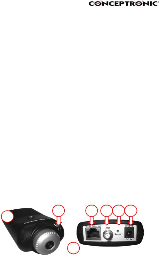
3.Explanation of the controls
This section describes the externally visible features of the Wireless Internet Camera.
2 |
4 |
5 |
6 |
7 |
1 
 3
3

1. Screw Hole
Located on the top/bottom panel of the camera, the screw hole is used to connect the camera stand onto the camera by attaching the screw head on the camera stand into the screw hole of the camera.
2. Power and Link LED
The Power LED is positioned on the right side of the Wireless Internet Camera’s lens while facing the Wireless Internet Camera. A steady BLUE light confirms that the Wireless Internet Camera is powered on.
The Link LED is positioned on the right side of the Wireless Internet Camera’s lens while facing the Wireless Internet Camera. It is located right of the Power LED. A steady ORANGE light confirms that the camera has good connection to LAN connectivity. Dependent on the data traffic the LED will begin to flash to indicate that the Wireless Internet Camera is receiving/sending data from/to the network.
3. Lens Cap
By turning the Lens Cap to the right or the left, you can adjust the sharpness of the recording image.
4. Network Cable Connector
The Wireless Internet Camera’s rear panel features an RJ-45 connector for connections to 10Base-T Ethernet cabling or 100Base-TX Fast Ethernet cabling (which should be Category 5 twisted-pair cable). The port supports the N-Way protocol and “Auto-MDIX” function, allowing the Wireless Internet Camera to automatically detect or negotiate the transmission speed of the network.
5. External Antenna (Only on C54NETCAM)
The rotatable external antenna allows you to adjust its position to obtain the maximum signal.
6. Reset Button
Reset will be initiated when the reset button is pressed once, and Power LED begins to flash.
Factory Reset will be initiated when the reset button is pressed continuously for three seconds or when Power LED begins to light up. Release the reset button and the Power LED will begin to flash, indicating the Wireless Internet Camera is changing to factory reset. When factory reset is completed, the Wireless Internet Camera will be set to de fault on channel 11 and SSID is set as “NULL String” (This default setting will let the Wireless Internet Camera connect to ANY access point on the infrastructure network). The IP address will also return to the default setting as 192.168.0.20.
7. DC Power Connector
The DC power input connector is located on the Wireless Internet Camera’s rear panel, and is la beled DC5V with a single jack socket to supply power to the Wireless Internet Camera. Power will be generated when the power supply is connected to a wall outlet.

4. Hardware Installation
4.1. Attaching the Camera to the Stand
The Wireless Internet Camera comes with a camera stand (optional) with a swivel ball screw head that can be attached to the Wireless Internet Camera's bottom screw hole. Attach the camera stand to the Wireless Internet Camera and station it for your application. There are three holes located in the base of the camera stand allowing the Wireless Internet Camera to be mounted on the ceiling or any wall securely.
4.2. Connecting the Ethernet cable
Connect an Ethernet cable to the network cable connector located on the Wireless Internet Camera’s rear panel, and then attach it to the network.
4.3. Attaching the Power Supply
Attach the external power supply to the DC power input connector located on Wireless Internet Camera’s rear panel, and then connect it to your local power supply. HINT: You can confirm power source is supplied from the LED indicators label Power on the Wireless Internet Camera is illuminated.
5. Security
To ensure the highest security an d prevent unauthorized usage of the (Wireless) Internet Camera the Administrator has the exclusive privilege to access the System Administration for settings and control requirements to allow users the level of entry and authorize the privileges for all users. The (Wireless) Internet Camera supports multi-level password protection and access to
the Wireless Internet Camera is strictly restricted to defined the user who has a “User Name” and “User Password” that is assigned by the Administrator.
The administrator can release a public user name and password so when remote users access the Wire less Internet Camera they will have the right to view the image transmitted by the Wireless Internet Camera.
NOTE: Since the default settings are empty, it is highly recommended to set the "Admin ID" and "Admin Password" when you are the first time to use the (Wireless) Internet Camera. Once the ID and Password are defined, only the administrator has the acce ss to management the (Wireless) Internet Camera. This procedure should be done as soon as possible since the security featur es with the (Wireless) Internet Camera will not be enabled until the "Admin ID" and "Admin Password" is defined.
6. Using the (Wireless) IP Camera through the webbrowser
You can access and manage the Wireless Internet Camera through: 1) a web browser, and 2) the enclosed software IPView SE.
This chapter describes the Web Configuration Utility, and provides the instructions on using the camera with a web browser.
6.1. Web Configuration Utility
The (Wireless) Internet Camera can be configured with the Setup Wizard, or through its built-in Web-based Configuration. ( Extensive knowledge of LAN will be helpful in setting up the Wireless Internet Camera.) From the web browser, enter the default IP address to access the Welcome screen of the (Wireless) Internet Camera.
To configure your (Wireless) Internet Camera, type http://192.168.0.20 in the address box. The number is the default IP address of your (Wireless) Internet Camera. Then, press [Enter].
NOTE: The computer’s IP address must correspond with the camera’s IP address in the same segment for the two devices to communicate.
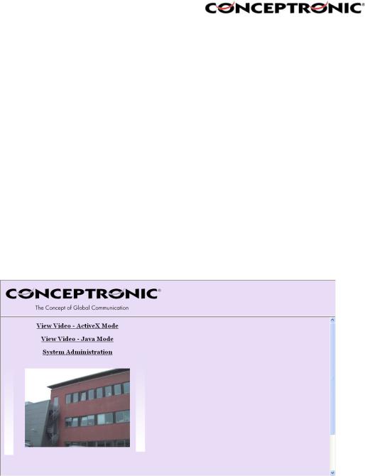
Welcome Screen of the Configuration Utility
After the default IP address is entered from the browser, the Wireless Internet Camera Welcome screen will appear with a still image. There will be three options to choose from to set-up and view your Wireless Internet Camera, including:
View Video – ActiveX Mode View Video – Java Mode System Administration
6.2. System Administration
Under the Welcome screen of the Configuration Utility, click System Administration to enter the administration window that contains the settings required for the camera in the top menu bar, including Management, Configuration, Tools, Help, and Home.
HINT: Once you have changed the settings in each option, click Save to store the settings, or Cancel to abandon, or Refresh to reload the status. During the configuration, whenever you click Home in the top menu bar will make you return to the Welcome window.

6.3. System Administration Æ Management
The Management window contains the information of your configuration. Click the items in the left column to view your settings, including: System, Video, Wireless, Network, and User.
6.3.1. System
Click the System item in the left column to display the device status of your camera.
- Device Status: The information about the camera, including the Camera Name, Location, Model, Firmware Version, MAC Address and IP Address, can be found in this field.
- Ethernet Status: You can monitor the networking status in this field, including the Link (network connection), Speed, and the Duplex mode.
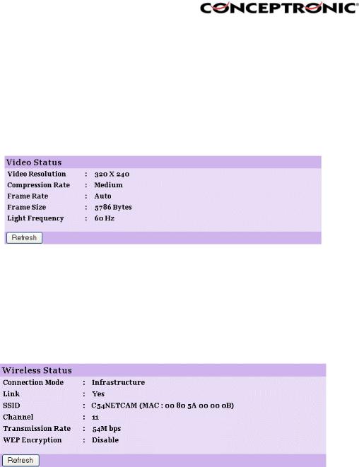
6.3.2. Video
Click the Video item in the left column to display the video configuration of your camera.
- Video Status: |
The video configuration about the camera, including the |
|
Video Resolution, Compression Rate, Frame Rate, Frame |
|
Size and IP Address, can be found in this field. |
6.3.3. Wireless (Only for C54NETCAM!)
Click the Wireless item in the left column to display the information of the wireless LAN.
- Wireless Status: |
The items in this field display the information of the wireless |
|
LAN, such as the Connection Mode (Infrastructure or Ad- |
|
Hoc), Link, SSID, Channel, Transmission Rate, and WEP |
|
Encryption. |
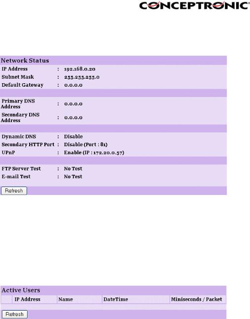
6.3.4. Network
Click the Network item in the left column to display the information of the LAN.
- Network Status: |
The items in this field display the information of the LAN, |
|
such as the IP Address, SubnetMask, Default Gateway, |
|
Primary DNS Address, Secondary DNS Address, Dynamic |
|
DNS, Secondary |
|
HTTP Port, and UPnP. |
6.3.5. User
Click the User item in the left column to display the user(s) information.
- Active Users: |
The items in this field display the user(s) information, |
|
including the user(s) IP address, Name, and DateTime. |
6.4 System Administration Æ Configuration
The Configuration window contains commands for settings that are required to input key details to setup the camera for operation. Click Configuration in the top menu bar and the configuration window will appear as below:
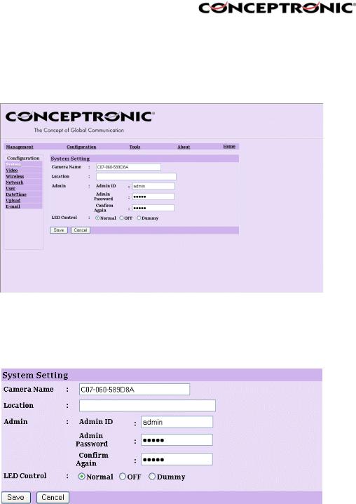
6.4.1. System
Click the System item in the left column to setup the basic configuration of your camera.
- Camera Name: |
This field is used to enter a descriptive name for the device. |
|
The default setting for the Camera Name is C07-060-xxxxxx, |
|
where xxxxxx is the last six digit of the MAC Address. The |
|
maximum |
- Location: |
length is 32 (printable ASCII). |
This field is used to enter a descriptive name for the location |
|
- Admin: |
used by the camera (optional). |
This field is used to enter the administrator name along with |
|
|
the password to access the System Administration settings. |
|
Be sure to enter the password twice to confirm the details |
|
once in the Admin Password field and again in the Confirm |
|
Password |
|
field. The default setting for administrator is empty, and you |
|
need to key in the administrator name with a maximum |
|
length of 12 (printable ASCII) characters and enter the |
|
administrator password with a maximum length of 8 |
|
|
(printable ASCII) characters. It is highly recommended to set |
|
|
the Admin ID and |
|
|
Admin Password as soon as possible to enable security |
- LED Control: |
option for the (Wireless) Internet Camera to function. |
|
This option allows user to setup the LED illumination as |
||
|
|
desired. This feature provides the flexibility when |
|
|
surveillance activity is ON. There are three options as |
|
|
follows: |
• |
Normal |
Power - Steady On of the LED indicator. |
|
|
Link - Steady On of the LED indicator. |
|
|
When WLAN activity is present the LED indicator will flash |
• |
|
steadily. |
OFF |
Power - LED indicator is off. |
|
• |
|
Link – LED indicator is off. |
Dummy |
Power - Steady On of the LED indicator. |
|
|
|
Link - Steady On of the LED indicator with random flashing. |
The default setting for the LED control is at Normal. When you have configured the LED control, the correct illumination will be set after 1 minute.
6.4.2. Video
Click the Video item in the left column to setup the image configuration of your camera.
- Video Resolution: |
Select the desired video resolution format, including |
- Compression Rate: |
160x120, 320x240 (default) and 640x480. |
Select the desired compression rate with five levels from |
|
|
Very Low to Very High. Higher video compression rate will |
|
generate more compact file size with less video quality and |
- Frame Rate: |
vise-versa. The default setting is Medium. |
Select the frame rate desired with default setting at Auto for |
|
- Brightness Control: |
optimal frame rate. |
Adjust the brightness level with default setting at 64. |
|
- Contrast Control: |
Adjust the contrast level with default setting at 64. |
- Saturation Control: |
Adjust the saturation with default setting at 64. |
- Light Frequency: |
Adjust the light frequency to suit your area of operation from |
|
the options either 50 Hz or 60 Hz (default). |
6.4.3. Wireless (Only for the C54NETCAM!)
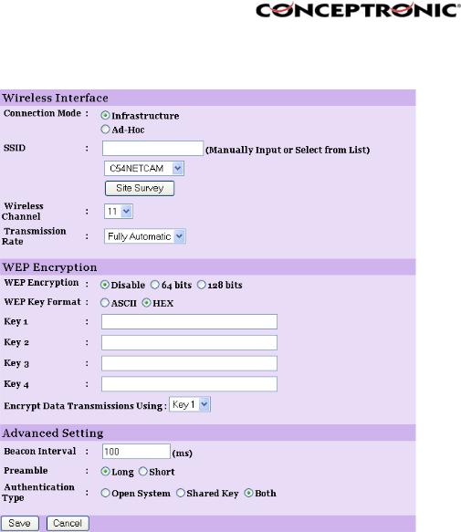
Click the Wireless item in the left column to setup the wireless LAN configuration of your camera.
- Connection Mode: |
Use this option to determine the type of wireless |
|
communication for your camera. |
|
There are two choices of Infrastructure mode and Ad-Hoc |
- SSID: |
mode. The default setting is Infrastructure. |
The SSID (Service Set Identifier) is the name assigned to the |
|
|
wireless network. It will auto-detect and display the SSID of |
|
wireless network connected in this box (it displays default |
|
initially). This default setting will let the camera connect to |
|
ANY access point under the infrastructure network mode. |
|
To connect the camera to a specific access point on the |
|
network, please make sure to set the SSID of the camera to |
|
correspond with the access point’s SSID for communication. |
|
Type any string up to 32 characters long (spaces, symbols, |
|
and punctuation are not allowed) in the Network Name box. |
|
To connect the camera to an Ad-Hoc wireless workgroup, |
|
make sure to set the same wireless channel and SSID to |
|
match with the PC/Notebook’s configuration for direct |
- Wireless Channel: |
wireless communication. |
This pull-down menu provides the wireless channel for |
|
|
communication. A "channel" is a range of frequencies to be |
|
used in communication between the camera and access |
|
point in Infrastructure mode, or the camera and PC/Notebook |
|
in Ad-Hoc |

|
mode. Select the appropriate channel from the list provided |
|
|
depending on the regulatory region where the unit is sold. |
|
- Transmission Rate: |
The default setting is at channel 11. |
|
Select the data transmit rate from this pull-down menu. The |
||
- WEP Encryption |
default setting is Fully Automatic. |
|
WEP Encryption: Wireless network communications can be |
||
|
intercepted easily. WEP (Wired Equivalent Privacy) is an |
|
|
encryption method specified by the IEEE 802.11g standard |
|
|
to make any intercepted communications extremely difficult |
|
|
to interpret by unauthorized parties. The default setting for |
|
|
this |
|
- WEP Key Format: |
option is Disable. |
|
To enable WEP Encryption, you should decide the |
||
|
encryption format first by selecting the ASCII or HEX option, |
|
- ASCII input format: |
and then input the WEP key (in the following Key 1~4 box). |
|
ASCII format causes each character you type to be |
||
|
interpreted as an eight-bit value. All unaccented upperand |
|
|
lower-case Western European characters that can be input |
|
|
through your keyboard's typing zone are valid. To setup a |
|
|
64-bit WEP key, input 5 ASCII characters. For example, |
|
|
‘12345’. To setup an 128-bit WEP key, input 13 ASCII |
|
|
characters. For example, ‘1234567890123’. These |
|
|
character counts result in bit counts of 40 and 104 |
|
|
respectively; the camera will automatically pad your input to |
|
- HEX input format: |
a bit count of 64 or 128. |
|
Hex format causes each pair of characters you type to be |
||
|
interpreted as an eight-bit value in hexadecimal (base 16) |
|
|
notation. Only the digits 0 through 9 and the letters A |
|
|
through F (in upper or lower case) are valid. To setup a 64- |
|
|
bit WEP key, input 10 HEX format. For example, |
|
|
‘3132333435’, which is the same with ASCII input ‘12345’. |
|
|
To setup an 128-bit WEP key, input 26 HEX format. For |
|
|
example, ‘31323334353637383930313233’, which is the |
|
|
same with ASCII input ‘1234567890123’. These character |
|
|
counts result in bit counts of 40 and 104, respectively; the |
|
|
Wireless Internet Camera will automatically pad your input to |
|
|
a bit count of 64 or 128. |
|
- Encrypt Data Transmissions Using: |
Use this pull-down menu to decide to use |
|
- Advanced Setting: |
|
Key 1, 2, 3 or 4 for encryption). |
In this field, you can setup more advanced configuration. |
||
- Beacon Interval: |
This option defines time interval between two images sent. |
|
- Preamble: |
A preamble is a signal used in wireless environment to |
|
|
synchronize the transmitting timing including Synchronization |
|
|
and Start frame delimiter. Please NOTE that if you want to |
|
|
change the Preamble type into Long or Short, please check |
|
- Authentication Type: |
the setting of access point. |
|
Open System communicates the key across the network. |
||
|
Shared Key |
allows communication only with other devices |
|
with identical WEP settings. The default setting is Both. |
|
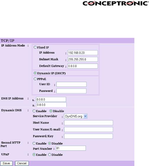
6.4.4. Network
Click the Network item in the left column to setup the LAN configuration of your camera.
- IP Address Mode: |
This field provides your with three options to select the IP |
|
- Fixed IP |
Address Mode: |
|
|
You can select this option and enter the IP address |
|
|
|
directly. The default settings are: |
|
|
IP Address – 192.168.0.20 |
|
|
Subnet Mask – 255.255.255.0 |
- Dynamic Address (DHCP) |
Default Gateway – 0.0.0.0 |
|
If your network uses the DHCP server, select this |
||
|
|
option. According to this setting, the camera will be |
|
|
assigned an IP address from the DHCP server |
|
|
automatically. Every time when the camera starts |
|
|
up, please make sure that the DHCP server is set to |
- PPPoE |
|
assign a static IP address to your camera. |
|
If your application requires a direct connection from |
|
|
|
an ADSL modem through the camera’s RJ-45 LAN |
|
|
port, click this option and enter the User ID and |
|
|
Password into the respective boxes. (You should |
|
|
have an ISP PPPoE account.) The camera will get |
- DNS IP Address: |
|
an IP address from the ISP as starting up. |
DNS (Domain Name System) server is an Internet service |
||
|
that translates domain names into IP addresses. Enter at |
|
- Dynamic DNS: |
least one DNS IP Address in this field. |
|
The Dynamic DNS service allows you to alias a dynamic IP |
||
|
address to a static hostname in any of the domains, allowing |
|
|
your computer to be more easily accessed from various |
|
|
locations on the Internet. |
|
 Loading...