

Comtrend CT-5071 DATASHEET
CT-5071
ADSL2+ Router
User’s Manual
Version A1.2, February 10, 2006
261063-004

Preface
This manual provides information to network administrators. It covers the
installation, operation and applications of the ADSL router.
The reader reading this manual is presumed to have a basic understanding of
telecommunications. For product update, new product release, manual revision,
software upgrade, technical support, etc., visit Comtrend Corporation at
http://www.comtrend.com
This document is subject to change without notice.
Warning
Before servicing or disassembling this equipment, always disconnect all
power and telephone lines from the device.
Use an appropriate power supply and a UL Listed telephone line cord.
Specification of the power supply is clearly stated in Appendix B Specifications.
Copyright
Copyright© 2006 Comtrend Corporation. All rights reserved. The information and
messages contained herein are proprietary to Comtrend Corporation. No part of this
document may be translated, transcribed, reproduced, in any form, or by any means
without prior written permission by Comtrend Corporation.
Technical support
When you find the product out of service, or that it doesn’t work properly, please
contact technical support engineer for immediate servicing or email to INT-
support@comtrend.com
1

Table of Contents
CHAPTER 1 INTRODUCTION................................................................................. 4
1.1 FEATURES ............................................................................................................ 4
1.2 A
1.3 F
PPLICATION ....................................................................................................... 5
RONT PANEL LED INDICATORS ......................................................................... 6
CHAPTER 2 INSTALLATION.................................................................................. 7
2.1 HARDWARE INSTALLATION.................................................................................. 7
CHAPTER 3 LOGIN VIA THE WEB BROWSER ................................... 8
3.1 IP ADDRESS ......................................................................................................... 8
3.2 L
3.2.1 Default Settings........................................................................................ 10
OGIN PROCEDURE .............................................................................................. 9
CHAPTER 4 QUICK SETUP ......................................................................... 11
4.1 AUTO QUICK SETUP........................................................................................... 12
4.2 M
ANUAL QUICK SETUP...................................................................................... 12
CHAPTER 5 DEVICE INFO............................................................................ 28
5.1 WAN................................................................................................................. 29
5.2 S
5.2.1 LAN Statistics ........................................................................................... 30
5.2.2 WAN Statistics .......................................................................................... 32
5.2.3 ATM statistics ........................................................................................... 33
5.2.4 ADSL Statistics ......................................................................................... 35
5.2.5 Route......................................................................................................... 37
5.2.6 ARP … .................................................................................................... 37
5.2.7 DHCP ......................................................................................................... 38
TATISTICS ........................................................................................................ 30
CHAPTER 6 ADVANCED SETUP................................................................ 39
6.1 WAN................................................................................................................. 39
6.2 LAN .................................................................................................................. 40
6.3
6.4 SECURITY........................................................................................................... 46
6.5 R
6.6 DNS................................................................................................................... 54
NAT ................................................................................................................. 41
6.3.1 Virtual Servers.......................................................................................... 41
6.3.2 Port Triggering.......................................................................................... 43
6.3.3 DMZ Host .................................................................................................. 45
6.4.1 Parental Control ...................................................................................... 46
6.4.2 MAC Filtering ............................................................................................ 47
6.4.3 IP Filtering ................................................................................................ 49
OUTING............................................................................................................ 52
6.5.1 Default Gateway....................................................................................... 52
6.5.2 Static Route .............................................................................................. 53
6.6.1 DNS Server ............................................................................................... 54
2

Dynamic DNS ........................................................................................... 54
6.6.2
6.7 DSL ................................................................................................................... 57
CHAPTER 7 DIAGNOSTICS.......................................................................... 58
CHAPTER 8 MANAGEMENT ....................................................................... 59
8.1 S
8.1.1 Configuration Backup............................................................................... 60
8.1.2 Configuration Restoration........................................................................ 60
8.1.3 Restore Default......................................................................................... 61
ETTINGS ........................................................................................................... 59
8.2 SYSTEM LOG...................................................................................................... 63
8.3 INTERNET TIME.................................................................................................. 65
8.4 A
8.4.1 Services .................................................................................................... 67
8.4.2 Access IP Addresses................................................................................. 68
8.4.3 Password Change ..................................................................................... 69
CCESS CONTROL.............................................................................................. 66
8.5 UPDATE SOFTWARE............................................................................................ 70
8.6 S
AVE AND REBOOT ............................................................................................ 71
APPENDIX A: PIN ASSIGNMENTS ................................................................ 72
APPENDIX B: SPECIFICATIONS.................................................................... 73
3

Chapter 1 Introduction
The CT-5071 is a wired Local Area Network ADSL2+ router. One 10/100 Base-T
Ethernet port provides wired LAN. The CT-5071 ADSL router provides state of the
art security features such as Firewall and VPN pass through. The CT-5071 is
designed for residential applications that require wired connectivity to an ADSL
broadband network. The CT-5071 supports up to 4 contiguous virtual connections
allowing for multiple simultaneous Internet connections.
1.1 Features
IP/MAC address filtering
Static route/RIP/RIP v2 routing functions
Dynamic IP assignment
NAT/PAT
IGMP Proxy
DHCP Server/Relay/Client
DNS Proxy
Up to 4 VCs
Web-based management
Remote configuration and upgrade
Configuration backup and restoration
FTP/TFTP server
4
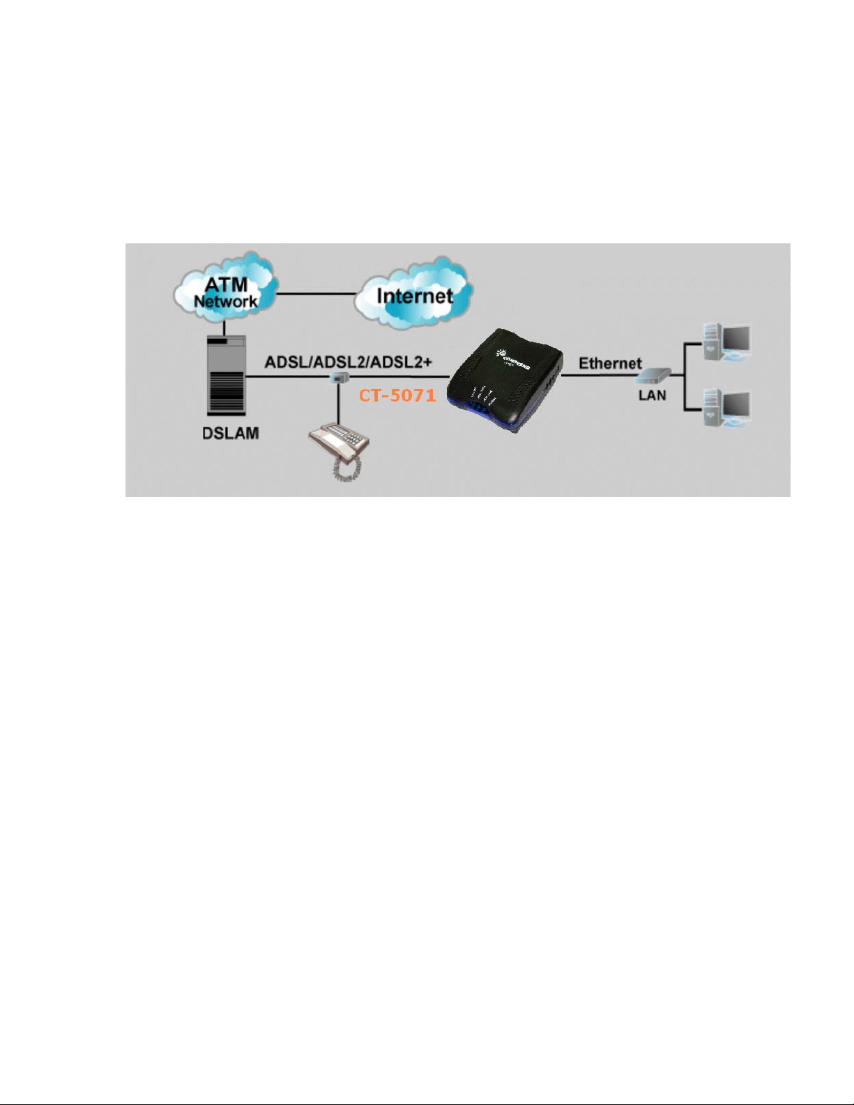
1.2 Application
The following diagram depicts the application of the CT-5071.
5
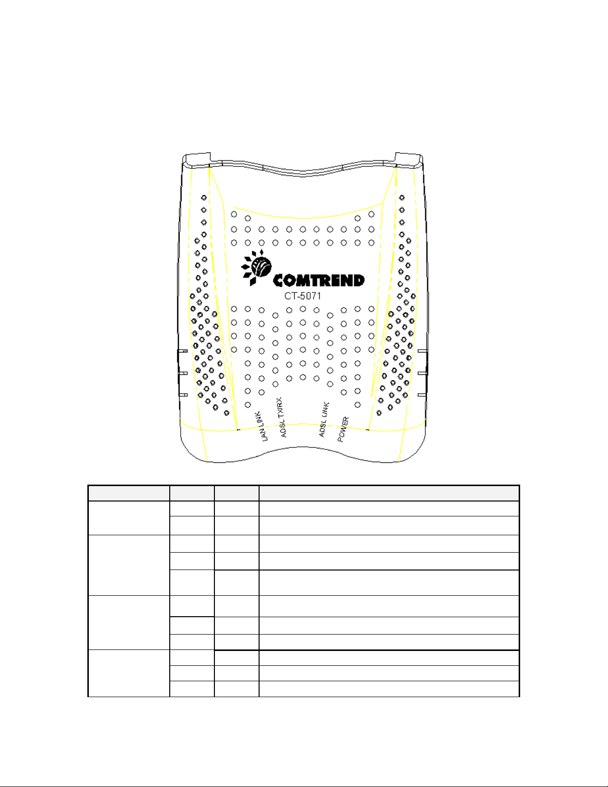
1.3 Front Panel LED Indicators
The front panel LEDs are shown in the picture below, followed by an
explanation in the table below.
LED Color Mode Function
Green On The router is powered up. POWER
Off The router is powered down.
ADSL LINK
ADSL
TX/RX
Green
Green
On The ADSL link is established.
Off The ADSL link is not established
Blink The ADSL link is training
On Normal operating status Green
Off The ADSL link is terminated.
Green Blink Data transmitting or receiving over ADSL.
LAN Link
Green On An Ethernet Link is established.
Off An Ethernet Link is not established.
Green Blink Data transmitting or receiving over LAN.
6
Chapter 2 Installation
g
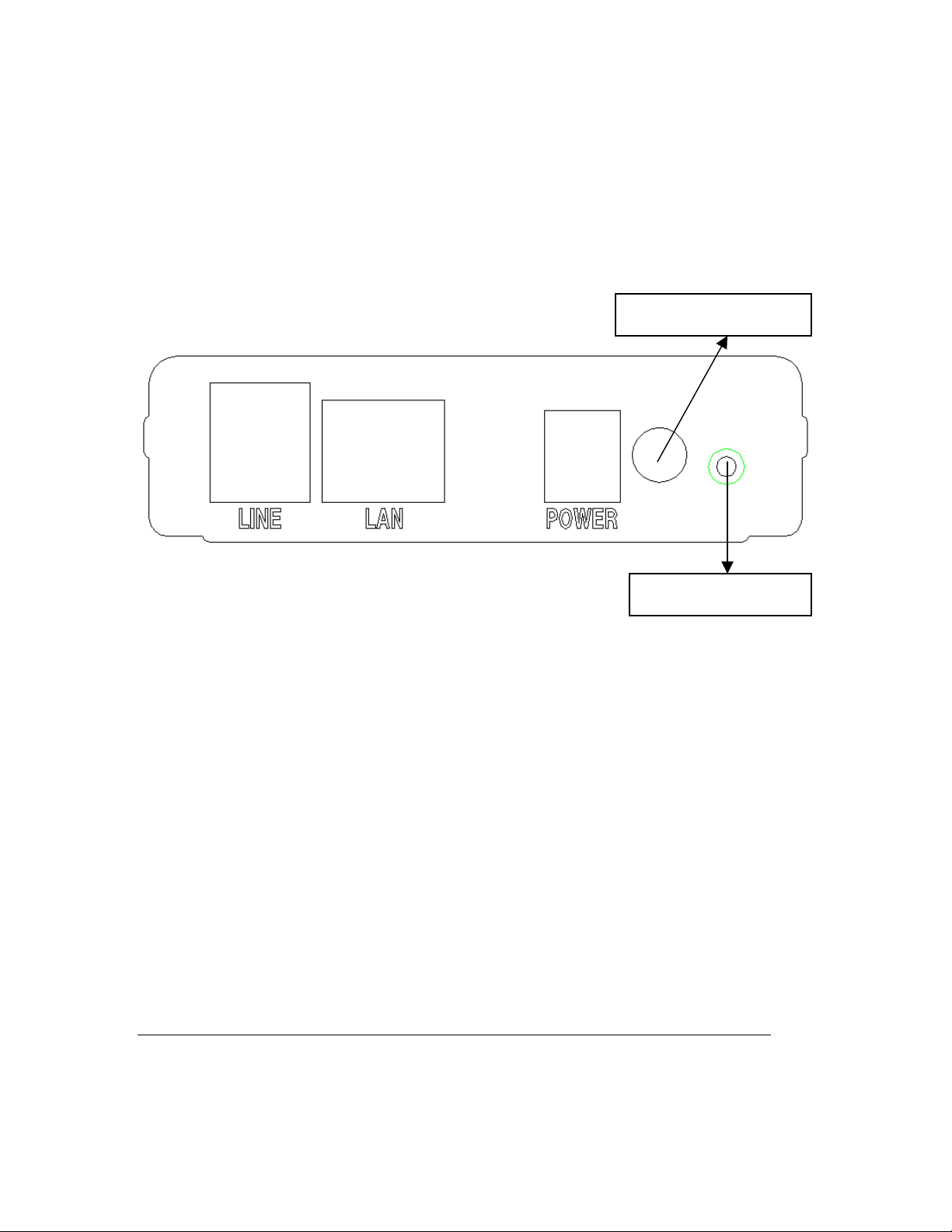
2.1 Hardware Installation
In the rear panel, there is a reset button. It is used to load the factory default
settings. Hold down the button until the LED’s start blinking simultaneously (about
5 seconds). After the device has booted successfully, the factory default settings are
retrieved.
Follow the instructions below to complete the hardware connections.
Connection to LINE port
If you wish to connect both the router and a telephone, connect the LINE port to a
POTS splitter with a RJ11 connection cable.
Connection to LAN port
To connect to a hub or PC, use a RJ45 cable. You can connect the router to up to
four LAN devices. The ports are auto-sensing MDI/X and either straight-through
cable or crossover cable can be used.
Connection to Power
Connect the Power jack to the shipped power cord. Attach the power adapter to the
wall outlet or other AC source.
After all connections have been made, push the power-switch in, to the on position.
After powering on, the router performs a self-test. Wait for a few seconds until the
test is finished, then the router will be ready to operate.
Caution 1: If the router fails to power up, or it malfunctions, first verify that the
power supply is connected correctly. Then power it on again. If the
problem persists, contact our technical support engineers.
Caution 2: Before servicin
this equipment always disconnect all power cords
Power Switch
Reset button
7
and telephone lines from the wall outlet.
Chapter 3 Login via the Web Browser
This section describes how to manage the router via a Web browser via the remote
end. You can use a web browser such as Microsoft Internet Explorer, or Netscape
Navigator. (The Web page is best viewed with Microsoft Internet Explorer 5.0 and
later): A unique default user account is assigned with user name root and password
12345. The user can change the default password later when logged in to the
device.
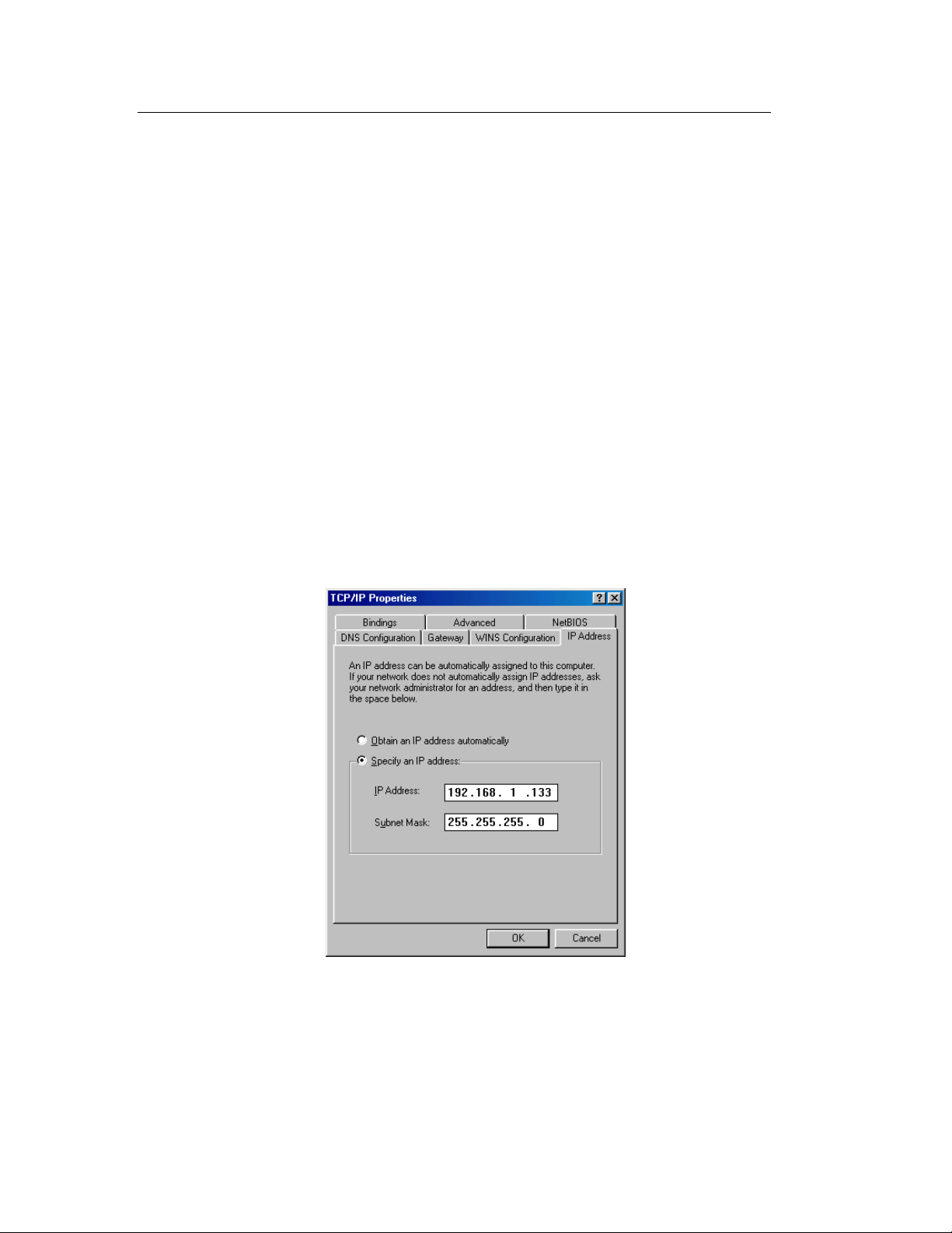
3.1 IP Address
The default IP address of the CT-5071 (LAN port) is 192.168.1.1. To configure the
CT-5071 for the first time, the configuration PC must have a static IP address within
the 192.168.1.x subnet. Follow the steps below to configure your PC IP address to
use subnet 192.168.1.x.
STEP 1: Right click on the Local Area Connection under the Network and Dial-Up
connection window and select Properties.
STEP 2: Enter the TCP/IP screen and change the IP address to the domain of
192.168.1.x/24.
STEP 3: Click OK to submit the settings.
STEP 4: Start your Internet browser with the default IP address 192.168.1.1.
8
3.2 Login Procedure
Perform the following steps to bring up the Web user interface and configure the CT-
5071. To log on to the system from the Web browser, follow the steps below:
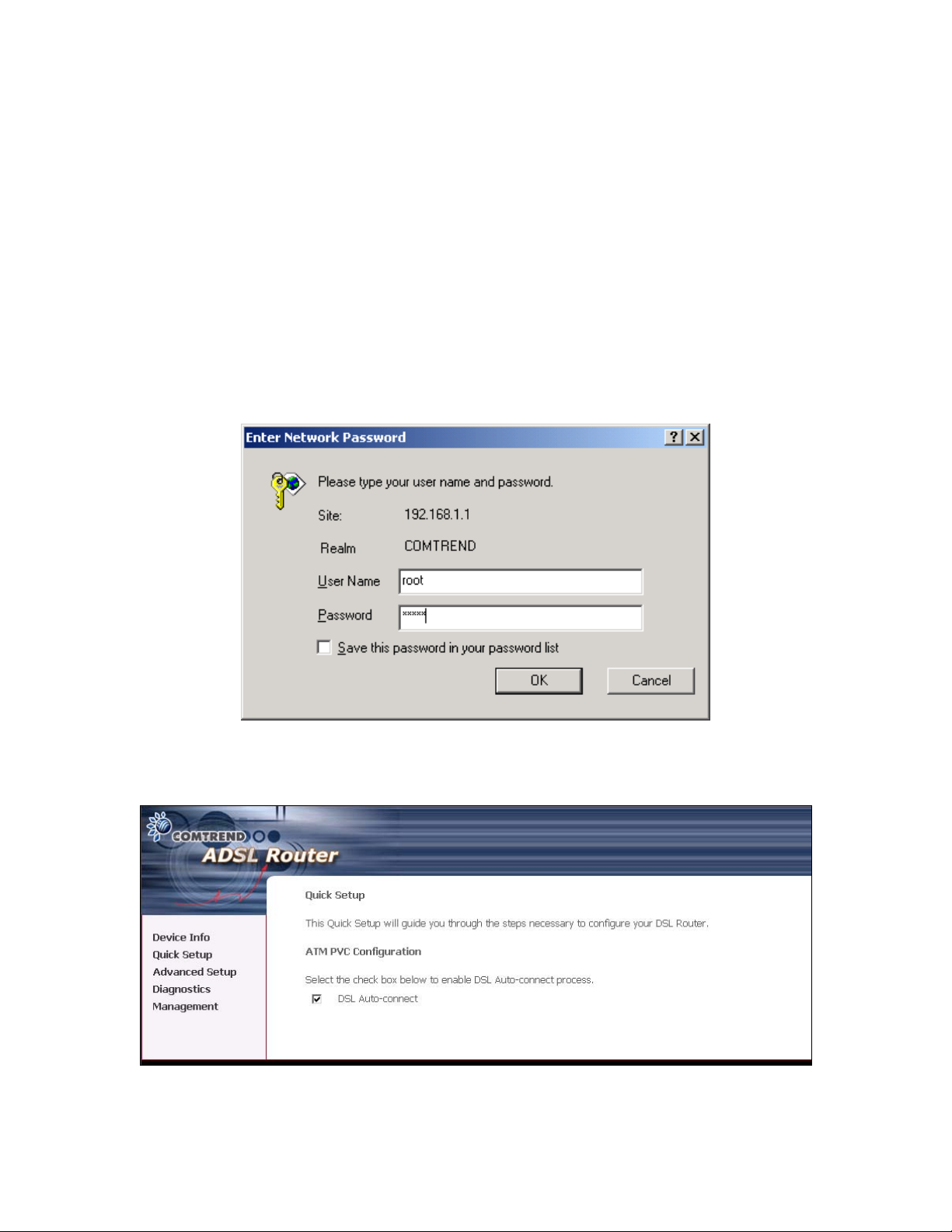
STEP 1: Start your Internet browser. Type the IP address for the router in the Web
address field. For example, if the IP address is 192.168.1.1, type
http://192.168.1.1
STEP 2:
You will be prompted to enter your user name and password.
Type root in the user name and 12345 in the password field,
and click OK.
Interface by selecting the Management link.
STEP 3: After successfully logging in, you will reach the Quick Setup menu.
These values can be changed later in the Web User
9

3.2.1 Default Settings
During power on initialization, the CT-5071 initializes all configuration attributes to
default values. It will then read the configuration profile from the Permanent
Storage section on the flash memory. The default attributes are overridden when
identical attributes with different values are configured. The configuration profile in
Permanent Storage can be created via the Web user interface or telnet user
interface, or other management protocols. To load the factory default settings, hold
the reset button down for at least 5 seconds until the power indicator blinks, or by
clicking the Restore Default Configuration option in the Restore Settings screen.
The following default settings are present when setting up the router for the first
time. The PC running the browser can be attached to the Ethernet.
LAN port IP address: 192.168.1.1
Local administrator account name: root
Local administrator account password: 12345
Remote WAN access: disabled
NAT and firewall: disabled
DHCP server on LAN interface: disabled
WAN IP address: none
10

Chapter 4 Quick Setup
The Quick Setup allows the user to configure the ADSL router for DSL connectivity
and Internet access. It also guides the user though the WAN network setup first and
then the LAN interface setup. You can either manually customize the router or follow
the online instruction to set up the router.
The CT-5071 ADSL router supports the following five network operating modes over
an ATM PVC WAN interface.
PPP over Ethernet (PPPoE)
PPP over ATM (PPPoA)
MAC Encapsulated Routing (MER)
IP over ATM (IPoA)
Bridging
The following configuration considerations apply:
The WAN network operating mode operation depends on the service provider’s
configuration on the Central Office side and Broadband Access Server for the
PVC
If the service provider provides PPPoE service, then the connection selection
depends on whether the LAN-side device (typically a PC) is running a PPPoE
client or whether the CT-5071 is to run the PPPoE client. The CT-5071 can
support both cases simultaneously.
If some or none of the LAN-side devices do not run PPPoE client, then select
PPPoE. If every LAN-side device is running a PPPoE client, then select Bridge In
PPPoE mode, CT-5071 also supports pass-through PPPoE sessions from the LAN
side while simultaneously running a PPPoE client fro non-PPPoE LAN devices.
NAPT and firewall are always enabled when PPPoE mode is selected, but they
can be enabled or disabled by the user when MER or IPoA is selected, NAPT and
firewall are always disabled when Bridge mode is selected.
Depending on the network operating mode, and whether NAPT and firewall are
enabled or disabled, the main panel will display or hide the NAPT/Firewall menu.
For instance, at initial setup, the default network operating mode is Bridge. The
main panel will not show the NAPT and Firewall menu.
Note: Up to eight PVC profiles can be configured and saved on the flash memory.
To activate a particular PVC profile, you need to navigate all the Quick Setup
pages until the last summary page, then click on the Finish button and reboot the
system.
11
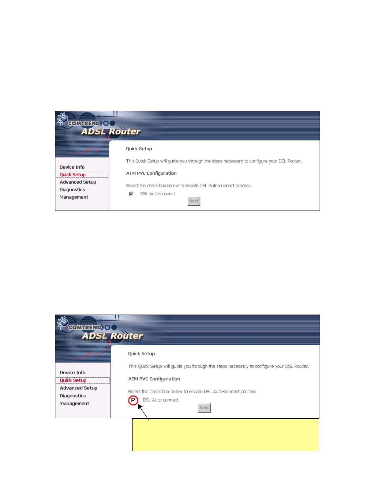
4.1 Auto Quick Setup
The auto quick setup requires the ADSL link to be up. The ADSL router will
automatically detect the PVC. You only need to follow the online instructions that
you are prompted.
1. Select Quick Setup to display the DSL Quick Setup screen.
2. Click Next to start the setup process. Follow the online instructions to complete
the setting. This procedure will skip some processes like PVC index, or
encapsulation.
3. After the settings are complete, you can use the ADSL service.
4.2 Manual Quick Setup
STEP 1: Click Quick Setup and un-tick the DSL Auto-connect checkbox to enable
manual configuration of the connection type.
Un-tick this checkbox to enable manual setup and display
the following screen.
12

STEP 2: Enter the Virtual Path Identifier (VPI) and Virtual Channel Identifier (VCI).
Select Enable Quality Of Service if required. Click Next.
STEP 3: Then, choose the Encapsulation mode.
STEP 4: Click Next to display the following screen. Choosing different connection
types pops up different settings requests. Enter appropriate settings that are
requested by your service provider. The following descriptions state each
connection type setup separately.
13
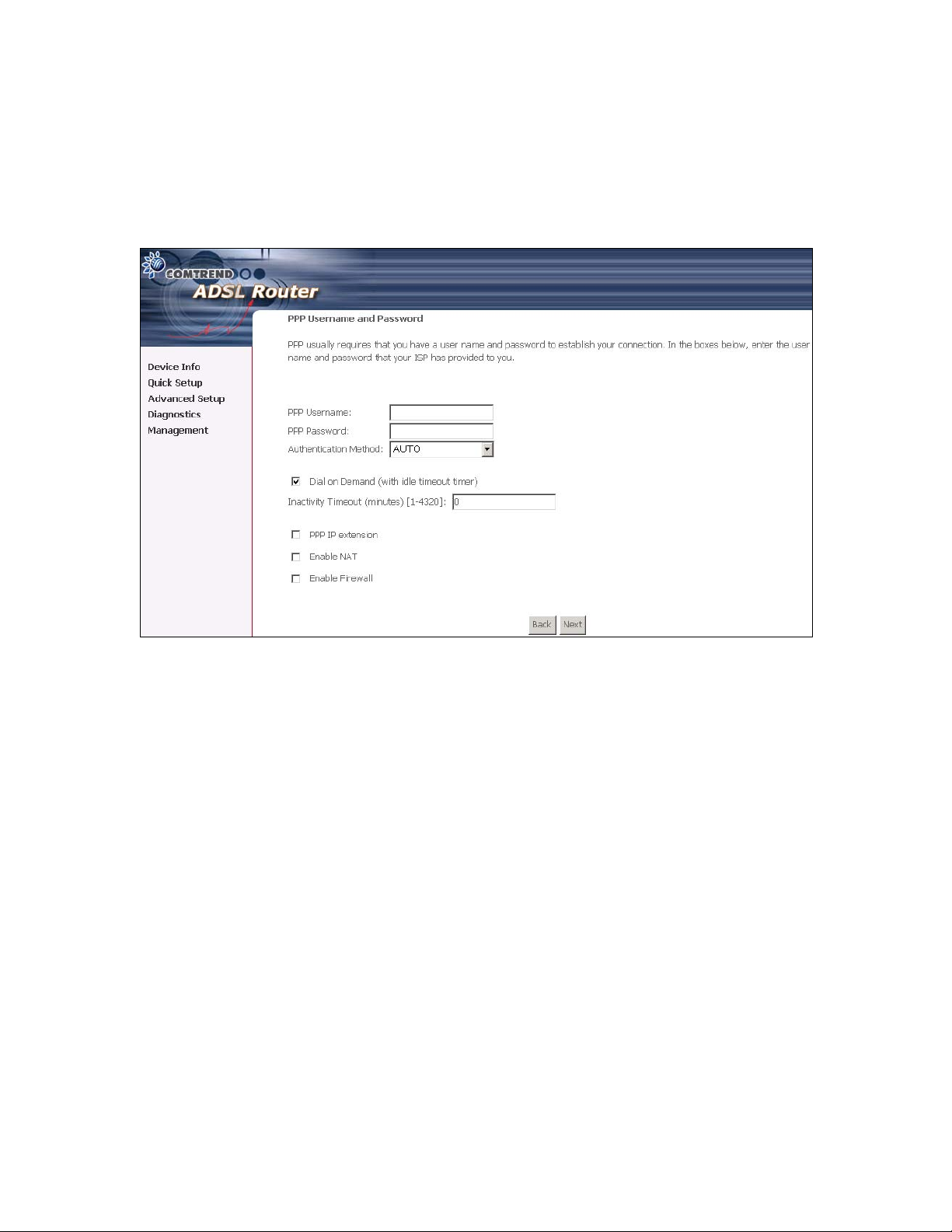
PPP over ATM (PPPoA) and PPP over Ethernet (PPPoE)
1. Select the PPP over ATM (PPPoA) or PPP over Ethernet (PPPoE) radio
button and click Next. The following screen appears:
PPP USERNAME/PPP PASSWORD
The PPP Username and the PPP password requirement are dependent on the
particular requirements of the ISP or the ADSL service provider. The WEB user
interface allows a maximum of 256 characters in the PPP user name and a maximum
of 32 characters in PPP password.
Encapsulation Mode
Choosing different connection types provides different encapsulation modes.
PPPoA- VC/MUX, LLC/ENCAPSULATION
PPPoE- LLC/SNAP BRIDGING, VC/MUX
MER- LLC/SNAP-BRIDGING, VC/MUX
IPoA- LLC/SNAP-ROUTING, VC MUX
Bridging- LLC/SNAP-BRIDGING, VC/MUX
14
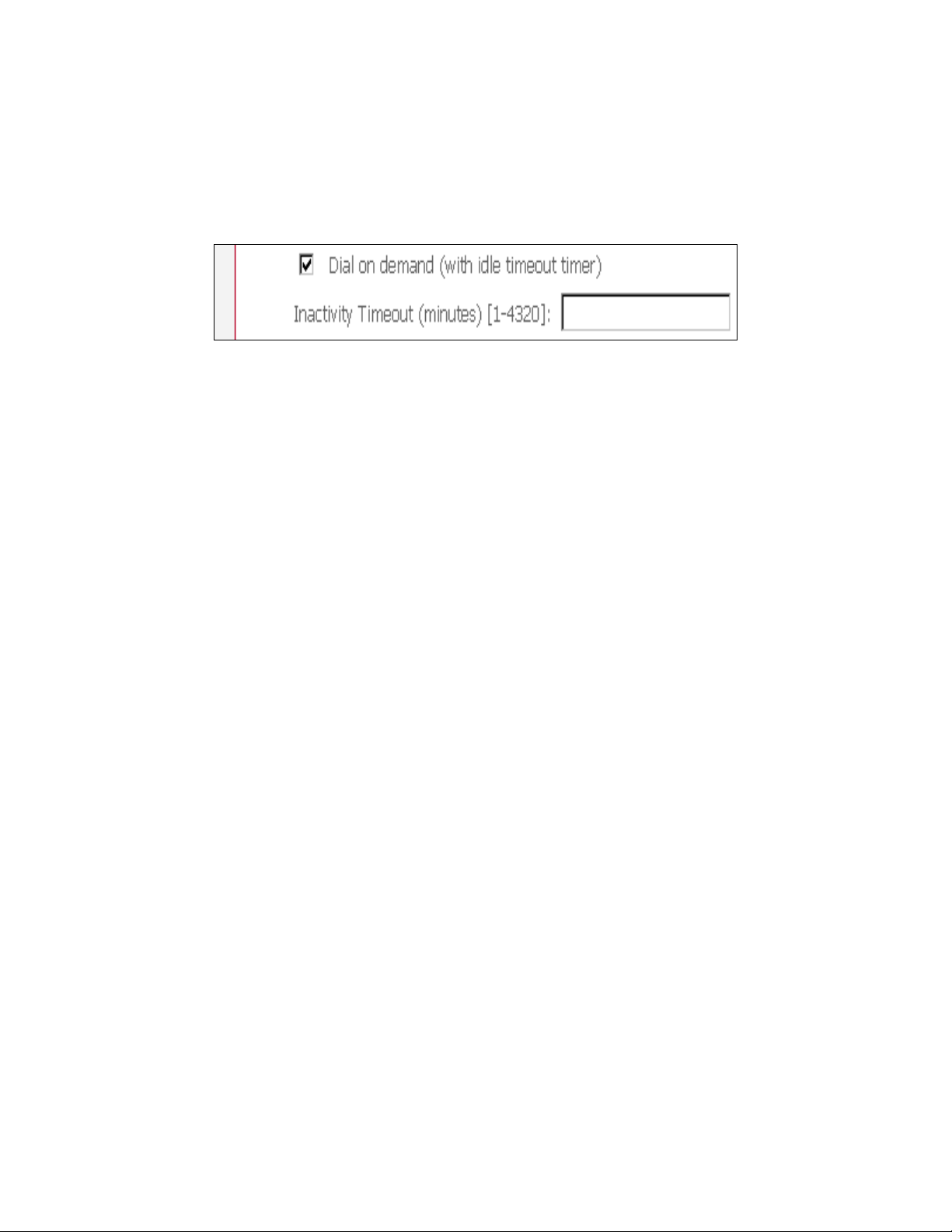
Disconnect if no activity
The CT-5071 can be configured to disconnect if there is no activity for a period of
time by selecting the Disconnect if no activity check box. When the checkbox is
ticked, you need to enter the inactivity timeout period. The timeout period ranges
from 1 minute to 4320 minutes.
PPP IP Extension
The PPP IP Extension is a special feature deployed by some service providers. Unless
your service provider specially requires this setup, do not select it.
The PPP IP Extension supports the following conditions:
Allows only one PC on the LAN
The public IP address assigned by the remote side using the PPP/IPCP protocol
is actually not used on the WAN PPP interface. Instead, it is forwarded to the
PC’s LAN interface through DHCP. Only one PC on the LAN can be connected to
the remote, since the DHCP server within the ADSL router has a single IP
address to assign to a LAN device.
NAPT and firewall are disabled when this option is selected.
The ADSL router becomes the default gateway and DNS server to the PC
through DHCP using the LAN interface IP address.
The ADSL router extends the IP subnet at the remote service provider to the
LAN PC. That is, the PC becomes a host belonging to the same IP subnet.
The ADSL router bridges the IP packets between WAN and LAN ports, unless the
packet is addressed to the router’s LAN IP address.
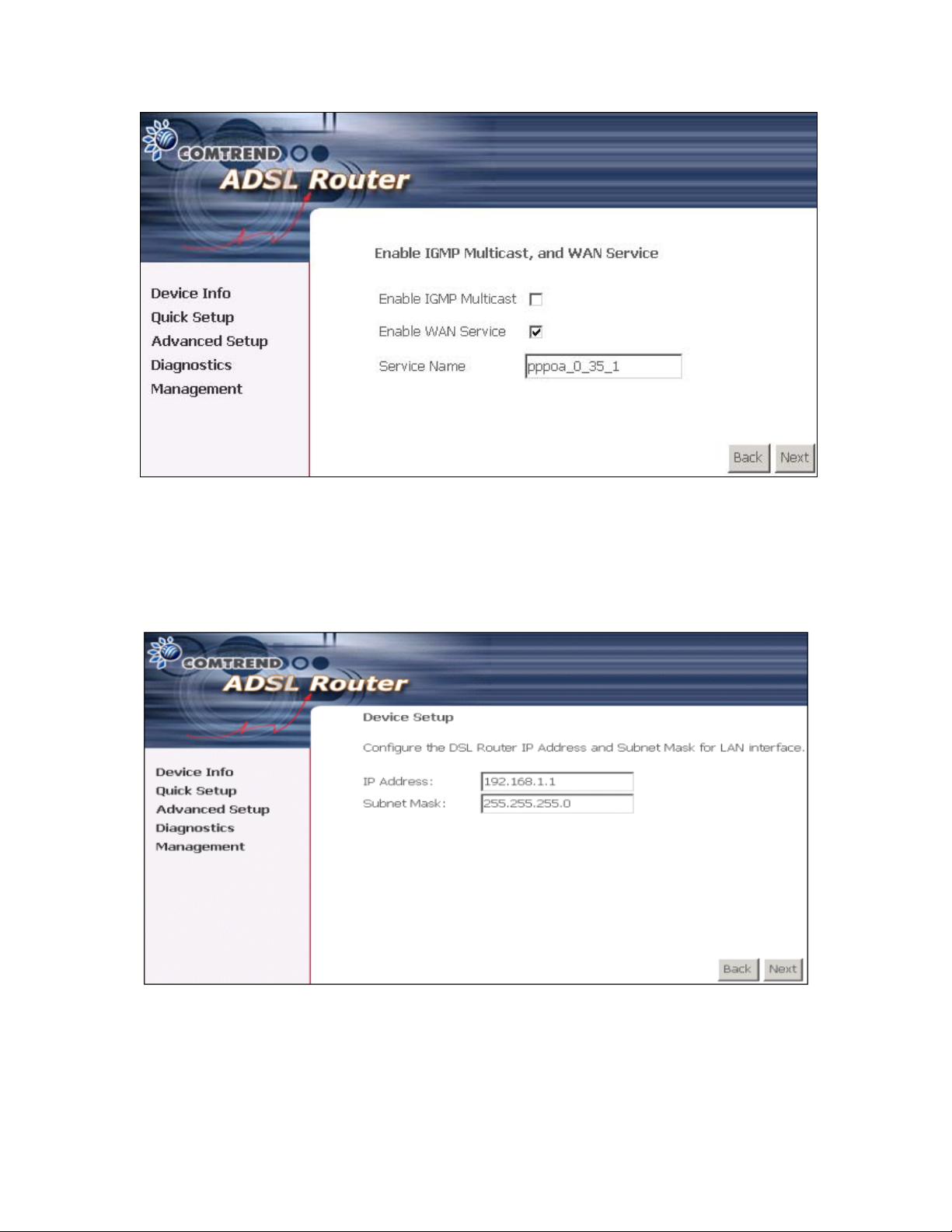
2. Click Next to display the screen below.
Enable IGMP Multicast checkbox: Tick the checkbox to enable IGMP multicast
(proxy). IGMP (Internet Group Membership Protocol) is a protocol used by IP hosts
to report their multicast group memberships to any immediately neighboring
multicast routers.
Enable WAN Service checkbox: Tick this item to enable the ADSL service. Untick
it to stop the ADSL service.
Service Name: This is user-defined.
15
3. After entering your settings, select Next. The following screen appears. This page
allows the user to configure the LAN interface IP address, subnet mask and DHCP
server. If the user would like this ADSL router to assign dynamic IP address, DNS
server and default gateways to other LAN devices, select the button Enable DHCP
server on the LAN to enter the starting IP address and end IP address and DHCP
leased time.
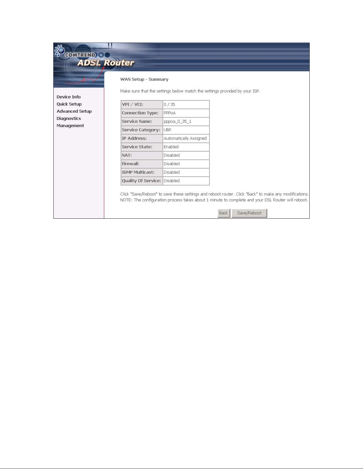
4. Click Next to display the WAN Setup-Summary screen that presents the entire
configuration summary. Click Save/Reboot if the settings are correct. Click Back
if you wish to modify the settings.
16
5. After clicking Save/Reboot, the router will save the configuration to the flash
memory, and reboot. The Web UI will not respond until the system is brought up
again. After the system is up, the Web UI will refresh to the Device Info page
automatically. The CT-5071 is ready for operation and the LEDs display as described
in the LED description tables.
17
MAC Encapsulation Routing (MER)
To configure MER, do the following.
1. Select Quick Setup and click Next.
2. Enter the PVC Index provided by the ISP and click Next and click Next
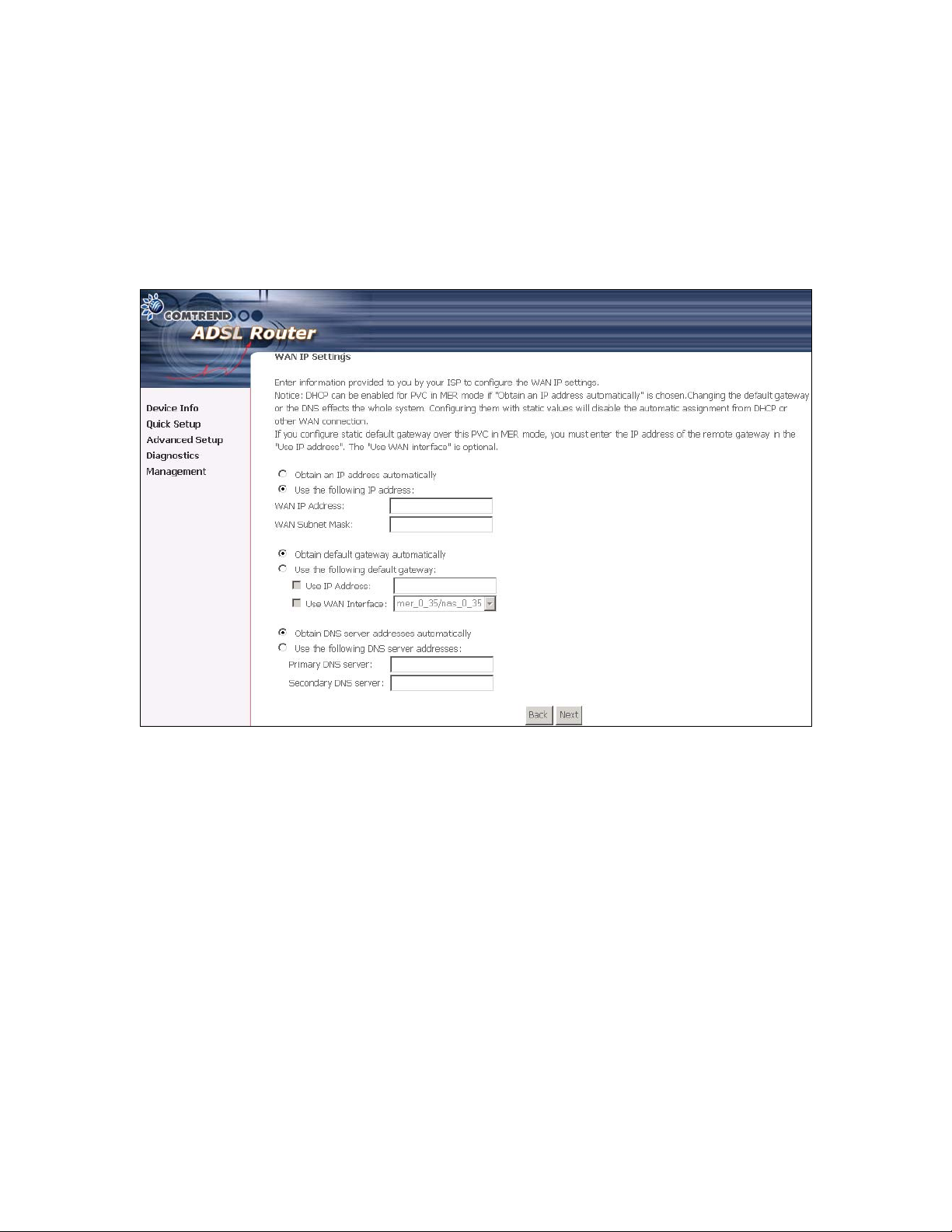
3. Select the MAC Encapsulation Routing (MER) radio button, and click Next. The
following screen appears.
Enter information provided to you by your ISP to configure the WAN IP settings.
Notice: DHCP can be enabled for PVC in MER mode if Obtain an IP address
automatically is chosen. Changing the default gateway or the DNS effects the
whole system. Configuring them with static values will disable the automatic
assignment from DHCP or other WAN connection.
If you configure static default gateway over this PVC in MER mode, you must enter
the IP address of the remote gateway in the "Use IP address". The "Use WAN
interface" is optional.
The ISP should provide the values that must be entered in the entry fields.
18
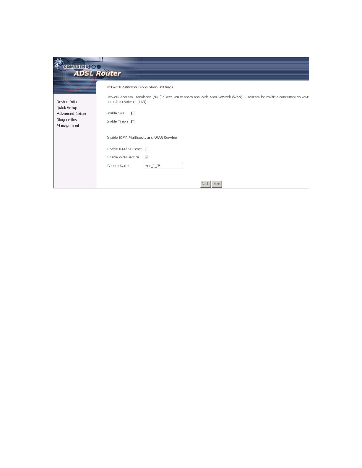
4. Click Next to display the following screen appears.
Enable NAT checkbox: If the LAN is configured with a private IP address, the user
should select this checkbox. The NAT submenu on the left side main panel will be
displayed after reboot. The user can then configure NAT-related features after the
system comes up. If a private IP address is not used on the LAN side, this checkbox
should be de-selected to free up system resources for better performance. When the
system comes back after reboot, the NAT submenu will not be displayed on the left
main panel.
Enable Firewall checkbox: If the firewall checkbox is selected, the firewall
submenu on the left side main panel will be displayed after system reboot. The user
can then configure firewall features after the system comes up. If firewall is not
used, this checkbox should be de-selected to free up system resources for better
performance. When system comes back after reboot, the Firewall submenu will not
be displayed on the left main panel.
Enable IGMP Multicast: Tick the checkbox to enable IGMP multicast (proxy). IGMP
(Internet Group Membership Protocol) is a protocol used by IP hosts to report their
multicast group memberships to any immediately neighboring multicast routers.
Enable WAN Service: Tick the checkbox to enable the WAN (ADSL) service. If this
item is not selected, you will not be able to use the ADSL service.
Service Name: This is User-defined.
19
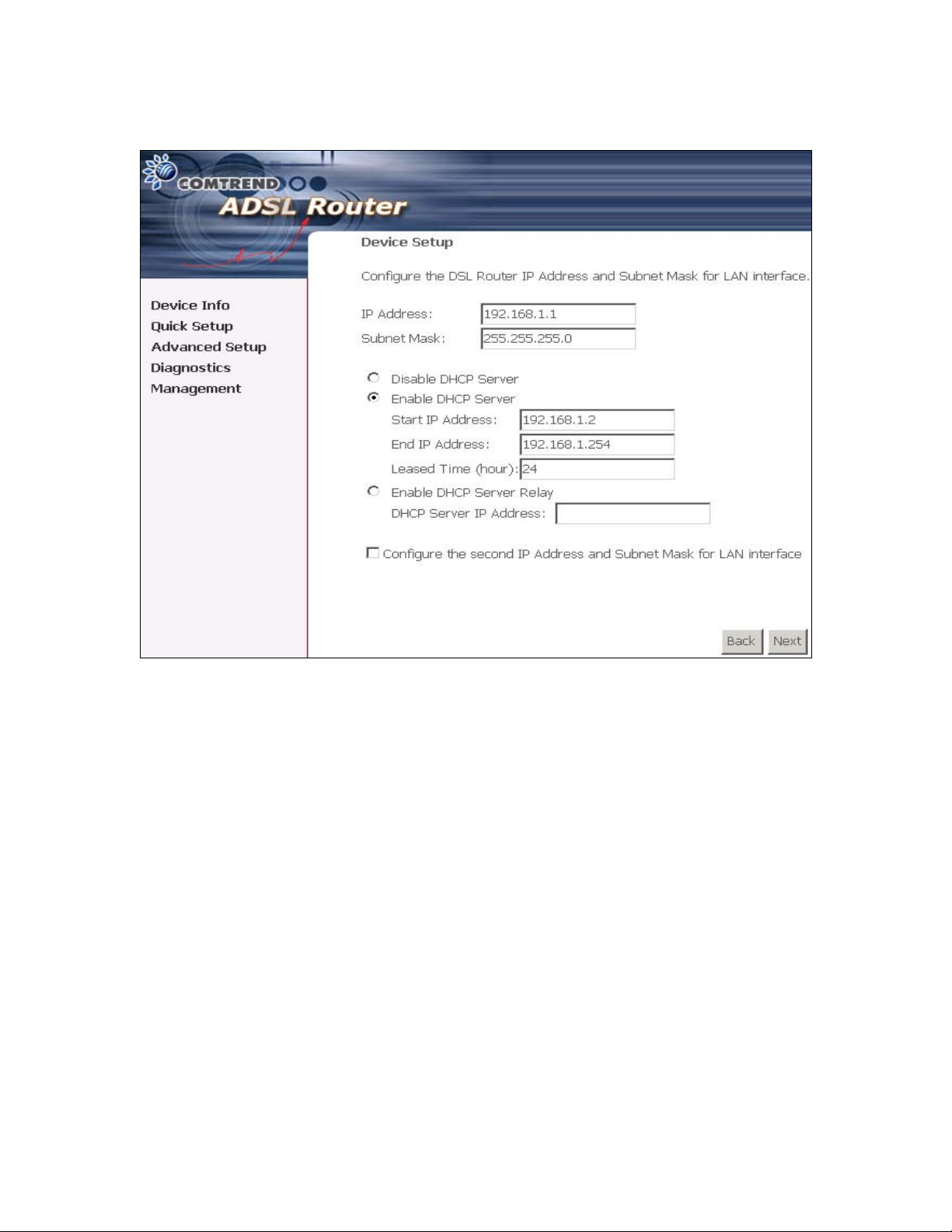
5. Upon completion, click Next. The following screen appears.
The Device Setup page allows the user to configure the LAN interface IP address and
DHCP server. If the user would like this ADSL router to assign dynamic IP
addresses, DNS server and default gateway to other LAN devices, select the radio
box Enable DHCP server on the LAN to enter the starting IP address and end IP
address and DHCP lease time. This configures the router to automatically assign IP
addresses, default gateway address and DNS server addresses to each of your PCs.
Note that the router’s default IP address is 192.168.1.1 and the default private
address range provided by the ISP server in the router is 192.168.1.2 through
192.168.1.254.
6. After entering your settings, select Next to display the following screen. The
WAN Setup-Summary screen presents the entire configuration summary. Click
Save/Reboot if the settings are correct. Click Back if you wish to modify the
settings.
The following screen will be displayed.
20
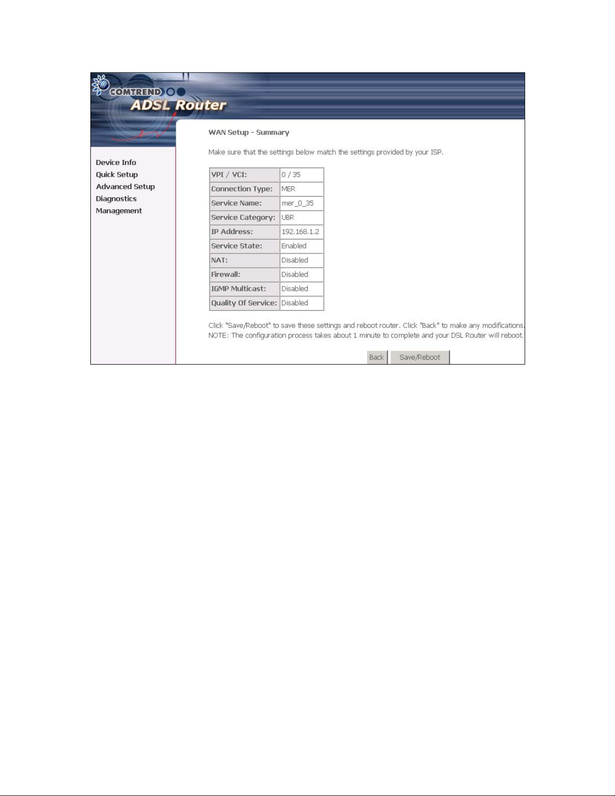
After clicking Save/Reboot, the router will save the configuration to the flash
memory, and reboot. The Web UI will not respond until the system is brought up
again. After the system is up, the Web UI will refresh to the Device Info page
automatically. The CT-5071 is ready for operation and the LEDs display as described
in the LED description tables.
21
IP Over ATM (IPoA)
To configure IP Over ATM,
1. Select Quick Setup and click Next.
2. Enter the PVC Index and click Next.
3. Type the VPI and VCI values provided by the ISP and click Next.
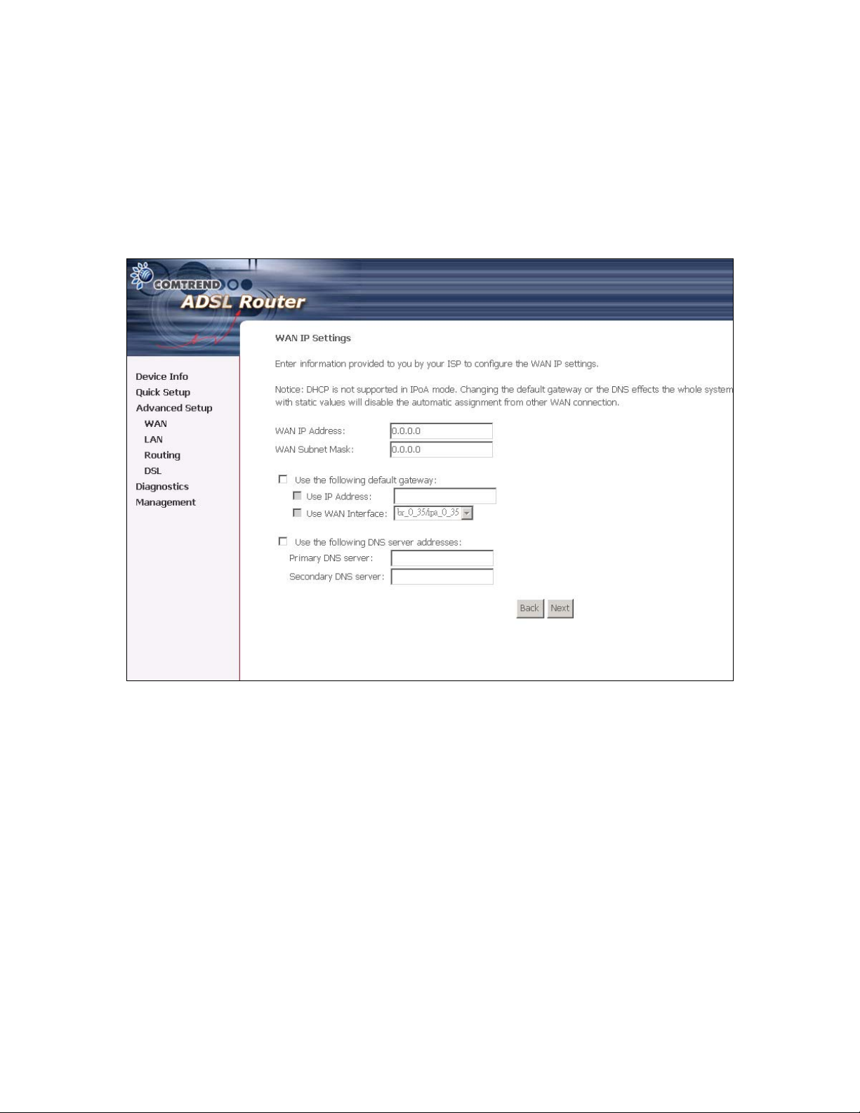
4. Select the IP over ATM (IPoA) radio button and click Next. The following screen
appears.
Notice that DHCP is not supported over IPoA. The user must enter the IP address or
WAN interface for the default gateway setup, and the DNS server addresses provided
by the ISP.
5. Click Next. The following screen appears.
22
 Loading...