

Page 1

MiniMAC
MiniMAC
MiniMACMiniMAC
Installation Manual
Installation Manual
Installation ManualInstallation Manual
Part Number MN/MiniMAC.IM
Revision 0
Page 2

Page 3

Comtech EFData is an ISO 9001 Registered Company
MiniMAC
MiniMAC
MiniMACMiniMAC
Rack Management System
Rack Management System
Rack Management SystemRack Management System
Installation Manual
Installation Manual
Installation ManualInstallation Manual
Part Number MN/MiniMAC.IM
Revision 0
May 31, 1999
Copyright © Comtech EFData, 2000
All rights reserved.
Printed in the USA.
Comtech EFData, 2114 West 7th Place, Tempe, Arizona 85281 USA, (480) 333.2200, FAX: (480) 333.2161.
Page 4

CHAPTER 1.
INTRODUCTION
1
This chapter describes an overview of the MiniMAC Rack Management System, referred
to in this manual as “MiniMAC.” The following subjects with section numbers are
described in this chapter:
Subject Section No.
Overview
Main Features
Port Expanders
Description
Overview Window
Control Window
Data and Report Generation
Environmental Specifications
1.1
1.1.1
1.1.2
1.2
1.2.1
1.2.2
1.2.3
1.4
1.1 Overview
The MiniMAC (Mini Monitor and Control) Rack Management System (Figure 1-1) is a
real-time, PC-based monitor and control system designed to interface with Adaptive
Broadband satellite modems, Radio Frequency (RF) terminals, switches, converters, and
other Adaptive Broadband equipment.
Rev. 0 1–1
Page 5

Chapter 2.
INSTALLATION
2
This chapter provides the equipment required and the mechanical setup for the MiniMAC
system. The following subjects with sect ion num bers are des cr ibed in this chapte r:
Subject Section No.
Unpacking
Equipment Inspection
Included Equipment
Fabrication Of Remote Cables
Rack Installation
COMM 3 Installation
COMM 4 Installation
COMM 5 Installation
COMM 6 Installation
COMM 7 Installation
COMM 8 Installation
COMM 9 Installation
Windows NT Installation
2.1
2.2
2.2.1
2.3
2.4
2.4.1
2.4.2
2.4.3
2.4.4
2.4.5
2.4.6
2.4.7
2.5
Rev. 0 2–1
Page 6

Chapter 3.
MiniMAC PROGRAM
3
This chapter describes the installation of the MiniMAC program. The following subjects
with section numbers are described in this section:
Subject Section No.
MiniMAC Program Setup
Install SENTINAL Driver
Install Port Expanders
Star Gate/ACL Procedures
Install Adapters
Install Properties
Enable Ports
MOXA Procedures
Install Adapters
Install Properties
Install ILCNCS
Install ILCNET and UINETMAN
Check Services after Restart
Verify ILCNET
Verify ILCUINETMAN
Create New File Folder for Customer Site
Verify
ActiveConfiguration
Create
ActiveConfiguration
Run MiniMAC Program
User Login
Exit MiniMAC Program from TASK MANAGER
File Folder
File Folder
3.1
3.2
3.3
3.3.1
3.3.1.1
3.3.1.2
3.3.1.3
3.3.2
3.3.2.1
3.3.2.2
3.4
3.4.1
3.4.2
3.4.2.1
3.4.2.2
3.5
3.6
3.6.1
3.7
3.8
3.9
Rev. 0 3–1
Page 7

Chapter 4.
REGISTRY EDITOR
4
This chapter describes the Registry Editor. The Registry Editor has all the system
configuration parameters for the MiniMAC operation. The following subjects with
section numbers are described in this section.
Subject Section No.
Path to Command Prompt
Opening the Registry Editor
Path to HOTKEY and COM Ports
Path to I LC Devices
Selecting a Path to Export
Exporting a Registry File
Naming the Registry File
4.1
4.2
4.2.1
4.2.2
4.3
4.4
4.4.1
Rev. 0 4–1
Page 8

Chapter 5
SERVICE PACK
5
This chapter provides information on the Windows NT Service Pack. The following
subjects with section numbers are described in this section.
Subject Section No.
Path to Service Pack
Service Pack
Install the Service Pack
Uninstall Options
Complete Installation
Restarting the Computer
Notes:
1. Service Pack is used when the Windows NT configuration has been altered. This
usually occurs when hardware or software has been added to the system. After
installing new hardware or new programs, it is recommended to run the Service
Pack.
2. It is not necessary to run Service Pack if the Registry File has been modified.
5.1
5.2
5.3
5.3.1
5.3.2
5.3.3
Rev. 0 5-1
Page 9

Chapter 6.
SYSTEM SETUP PROGRAM
6
This chapter describes the System Setup program for the MiniMAC program. This
program configures the COMM ports and adds Adaptive Broadband devices to each port.
The following subjects with section numbers are described in this section.
Subject Section No.
ILCNCS System Setup Program
Selecting Number of Computers
Entering the Computer Name
Setting Up the COMM Ports
Selecting COMM Ports for Device Setup
Adding a New Device
Selecting a New Device Type from the Device List
Configuring and Adding the New Device Type
Creating an EXCEL Spreadsh eet
Updating the System Registry
6.1
6.2
6.3
6.4
6.5
6.6
6.7
6.8
6.9
6.10
Rev. 0 6–1
Page 10

Chapter 7.
OVERVIEW EDITOR
PROGRAM
7
This chapter describes the overview editor program. This program builds the MiniMAC
overview screen. The following subjects with section numbers are described in this
section.
Subject Section No.
ILC Overview Editor Program
Opening the Overview.Mac F ile
Viewing the Overview Screen
Editing Item Properties
Viewing
Viewing the Selected Groups
Viewing the Remote Site
Loading New Devices
Selecting and Configuring New Devices
Saving Changes to th e Overview.Mac File
7.1
7.1.1
7.1.2
7.2
7.3
7.3.1
7.3.2
7.4
7.4.1
7.5
Rev. 0 7–1
Page 11

Appendix A.
A
A
This appendix describes necessary Windows NT functions required to operate in the
MiniMAC program. The following subjects with section numbers are described in this
section.
Subject Section No.
Windows NT
Computer Configuration
Path to Windows NT Diagnostics
Windows NT Diagnostics
Windows NT Diagnostic – IRQ
Windows NT Diagnostic – I/O Ports
Windows NT Diagnostic – Memory Allocation
Host File
IP Configuration Command
IP Configuration.Txt File
Debugging the Services
Saving Debug to a File
Remote Access Administration
Open Remote Access Administrator
Grant User Permission
Starting Remote Access Service
Verify Computer System Name
Attempt to Start Remote Access Administrator
Dealing with Errors
Path to Event Viewer
View the System Log
Setting Up the Dial in Port Usage
Checking the RAS Server TCP/ IP Address
Restarting the Computer
View Event Detail Information
A.1
A.1.1
A.2
A.2.1
A.2.2
A.2.3
A.2.4
A.2.5
A.2.6
A.2.7
A.3
A.3.1
A.4
A.4.1
A.4.2
A.4.3
A.4.4
A.4.5
A.4.6
A.4.7
A.4.8
A.4.8.1
A.4.9
A.4.10
A.4.11
DATA
Rev. 0 A–1
Page 12

Appendix B.
TROUBLESHOOTING
B
This appendix describes the troubleshooting guide that may be required during the
installation of the MiniMAC program .
Subject Section No.
Troubleshooting B.1
Rev. 0 B–1
Page 13

G
Glossary
The following is a list of acronyms and abbreviations that may be found in this manual.
Acronym/
Abbreviation
ACL Advanced Communication Link
ASYNC Asynchronous
BOP Breakout Panel
C Centigrade
COM Communication
cm Centimeter
CPU Central Processing Unit
DOS Data operating System
EISA Europe Industry Standard Architecture
exe Execute
F Fahrenheit
I/O Input/O utput
IBM
ILC Industrial Logic Corporation
ILCNCS Industrial Log ic C orpora tion N e tw ork C ontrol Sy s tem
IP Internet Protocol
IRQ Interupt Request
ISA Industry Standard Architect ure
EIA Electronic Industries Association
LED Liquid Emitter Diode
LPT Local Port Terminal
MiniMAC Mini Monitor and Control
PC Personal Computer or Printed Cir c uit
RAS Remote Access Server
RC Redundancy Controller
REGEDIT Registry Editor
RF Radio Frequency
RFT Radio Frequency Terminal
RMS Rack Management System
RS Recommended Standard
RSU Redundancy Switch Unit
International Business Machine
Definition
Rev. 0 g–1
Page 14

I
Index
Adding a New Device, 6–1, 6–7
Attempt to Start Remote Access Administrator, 1–6
Checking the RAS Server TCP/IP Address, 3–1, 3–14
COM 4 Installation, 2–1, 2–13
COM 6 Installation, 2–1, 2–16
COM 8 Installation, 2–1, 2–18
Complete Installation, 2–1, 2–20
Configure ILCNET, A–1, A–2
Configuring and Adding the New Device Type, 3–15
Create New File Folder for Customer Site, 3–1, 3–19
Creating an EXCEL Spreadsh eet, 7–8
Dealing with Errors, 1–1, 1–5
Editing Item Properties, A–1, A–12
Entering the Computer Name, 3–1, 3–7
Equipment Inspection, 1– 1, 1– 6
Exit MiniMAC Program, 1–5
Fabrication of Remote Cables, 2-4
Granting User Permission, A–16
Included Equipment, 7–1, 7–2
Install ILCNET and UINETMAN Services, 3–1, 3–11
Install MOXA Properties, 3–9
Install Properties, 3–4
Installation, 2–3
Installing Adapter Drivers, 3–1, 3–2
Interface, 2–3
MiniMAC Program Setup, 1– 1, 1–2
Naming the Registry File, 3–8
Opening the Overview.Mac F ile, A–1, A–15
Overview Window, 4–1, 4–2
Path to Event Viewer, 4– 1, 4–2
Path to the HOTKEY and COM Ports, 1, 2
Path to Windows NT Diagnostics, 4–5
Rack Installation, 1–1, 1–3, 1–4, 3–1
Restarting the Computer, A–1, A–15, A–19
Saving Changes to the Overview.Mac File, 3–1, 3–20
Saving Debug to File, A-13
Selecting a Path to Export , 6–8
Selecting COM P orts for Device Setup, 7–1, 7–10
Service Pack, 6–1, 6–3
Setting Up the COM Ports, 4
STAR GATE/ACL Procedures, A–1, A–24
Troubleshooting, 6–1, 6–2
Unpacking, 1, 5
User Login, 6– 1, 6–11
Verify ActiveConfiguration File Folder, A–18
View the System Log, A–1, A–23
Viewing Selected Groups, 7–7
Windows NT Diagnostics, 7–1, 7–4
Windows NT Diagnostics – IRQ, A–7
Windows NT, A–8
Windows NT Installation, 2–1, 2–21
Rev. 0 i–1
Page 15

Index MiniMAC Rack Mangement System
This page is intentionally left blank.
i–2 Rev. 0
Page 16

Glossary MiniMAC Rack Management System
SCS Satellite Converter Switch
SDC Satellite Data Converter
SDM Satellite Data Modem
SMS Satellite Modem Switch
SYS System
TCP Transport Communication Protocol
UINETMAN User Interface Network Manager
WIN Windows
g–2 Rev. 0
Page 17

Troubleshooting MiniMAC Rack Management System
B.1 Troubleshooting
Refer to Table B-1 if Windows NT does not operate with the MiniMAC program.
Table B-1. Troubleshooting
Problem Probable Cause Remedy
Upon computer startup,
Windows NT displays
message that a Driver
would not install.
ILCNET and UINETMAN
services will not run.
Port expander card has
conflicting IRQ, memory, or
address setting with a plug
and play device.
Name of computer (assigned
in Windows NT) does not
equal computer name
specified in the Registry
Editor.
Verify jumper or switch setting on the port expander
card. Use Windows Diagnostic (Appendix A) and
check settings. Reconfigure adapter properties as
outlined in Chapter 3.
Reidentify computer name.
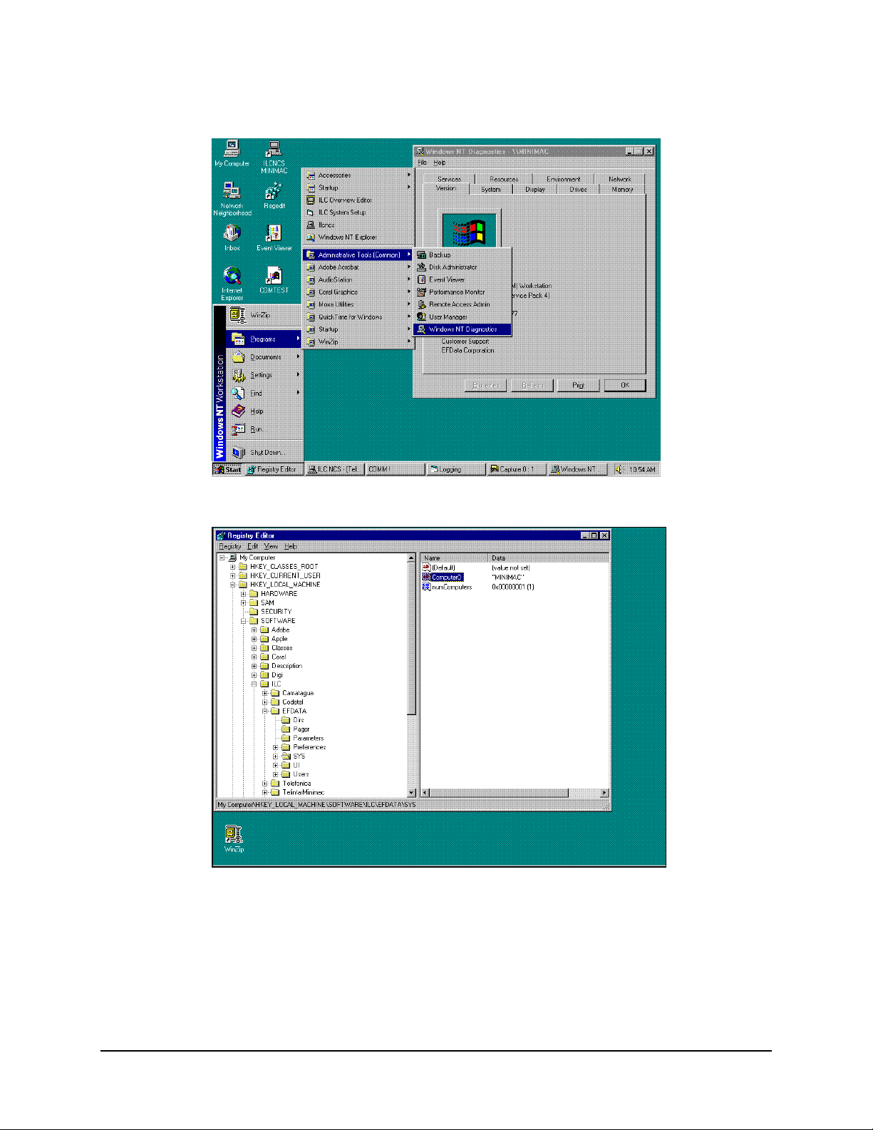
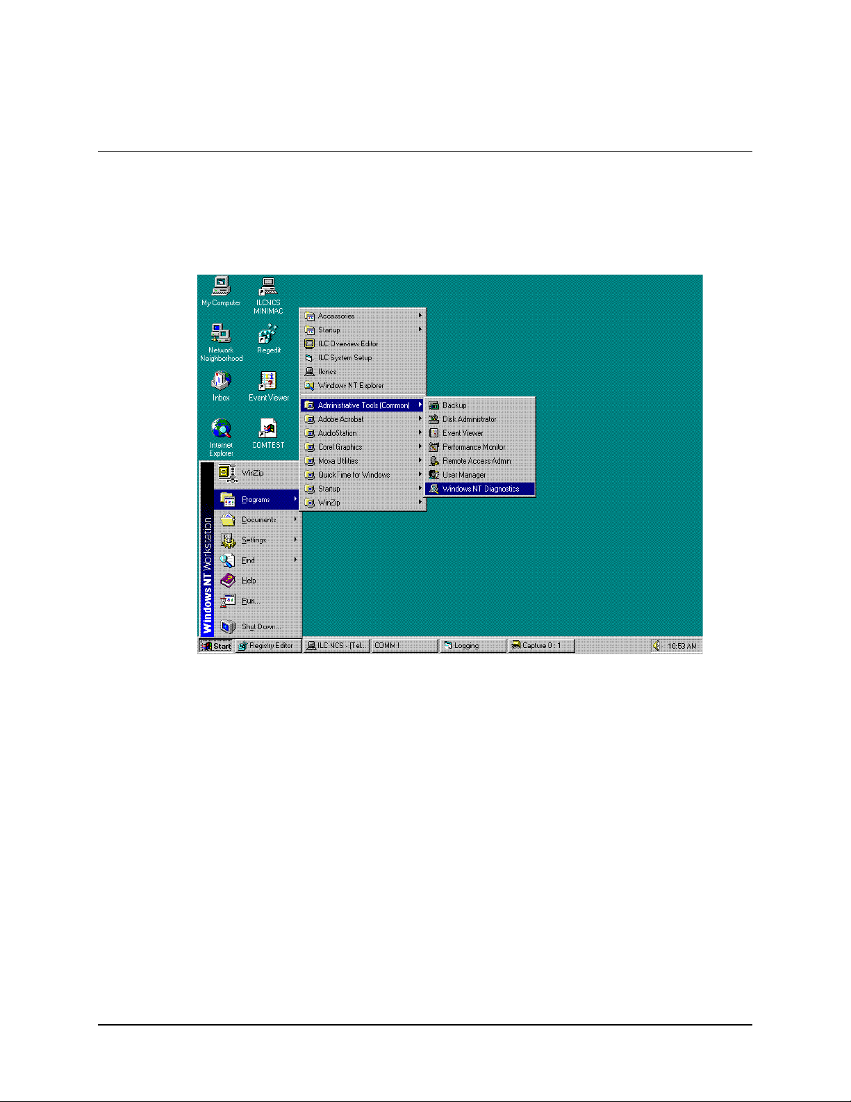
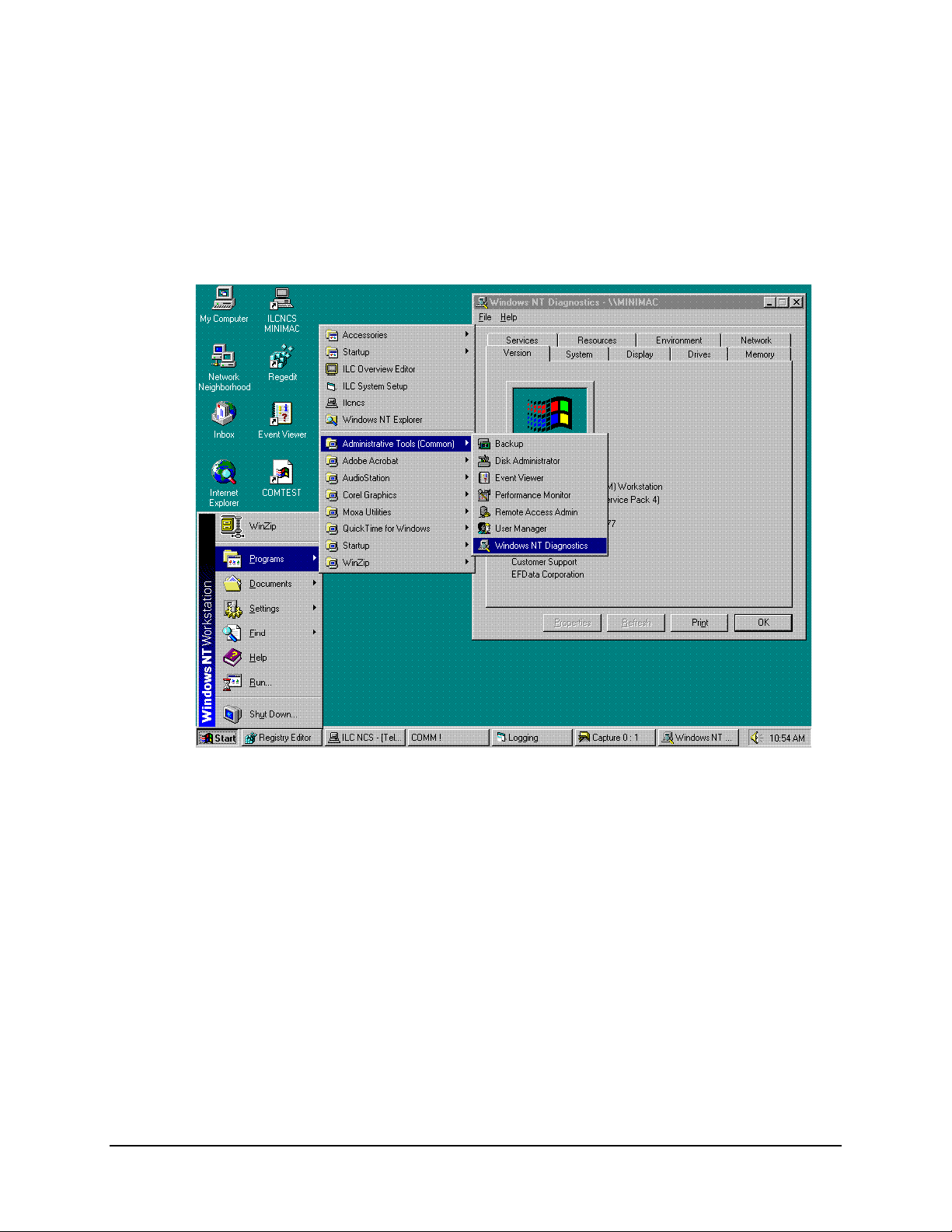
See Figure B-1:
Go to: START
Click on: PROGRAM
Click on: ADMINISTRATIVE TOOLS
Click on: WINDOWS NT DIANOGISTICS
Read: Top line (will exhibit name of computer)
ILCNET will run but,
UINETMAN will not run.
ILCNCS will not run. In the Registry Editor, ILC
ILCNCS will work but no
communication between
COMM ports and
MiniMAC.
Service can not find computer
name, although Registry File
is correct.
program directory path
improperly created or
BITMAP and/or DATABASE
file folders missing.
1. Hyperterm or
Commtest.exe is not disabled.
2. Port expander drivers are
not installed or improperly
installed.
Go to: EVENT VIEWER
Observe: Red logo will
describe event error.
3. Sentinel hardware key is
missing.
4. Sentinel Driver not
installed.
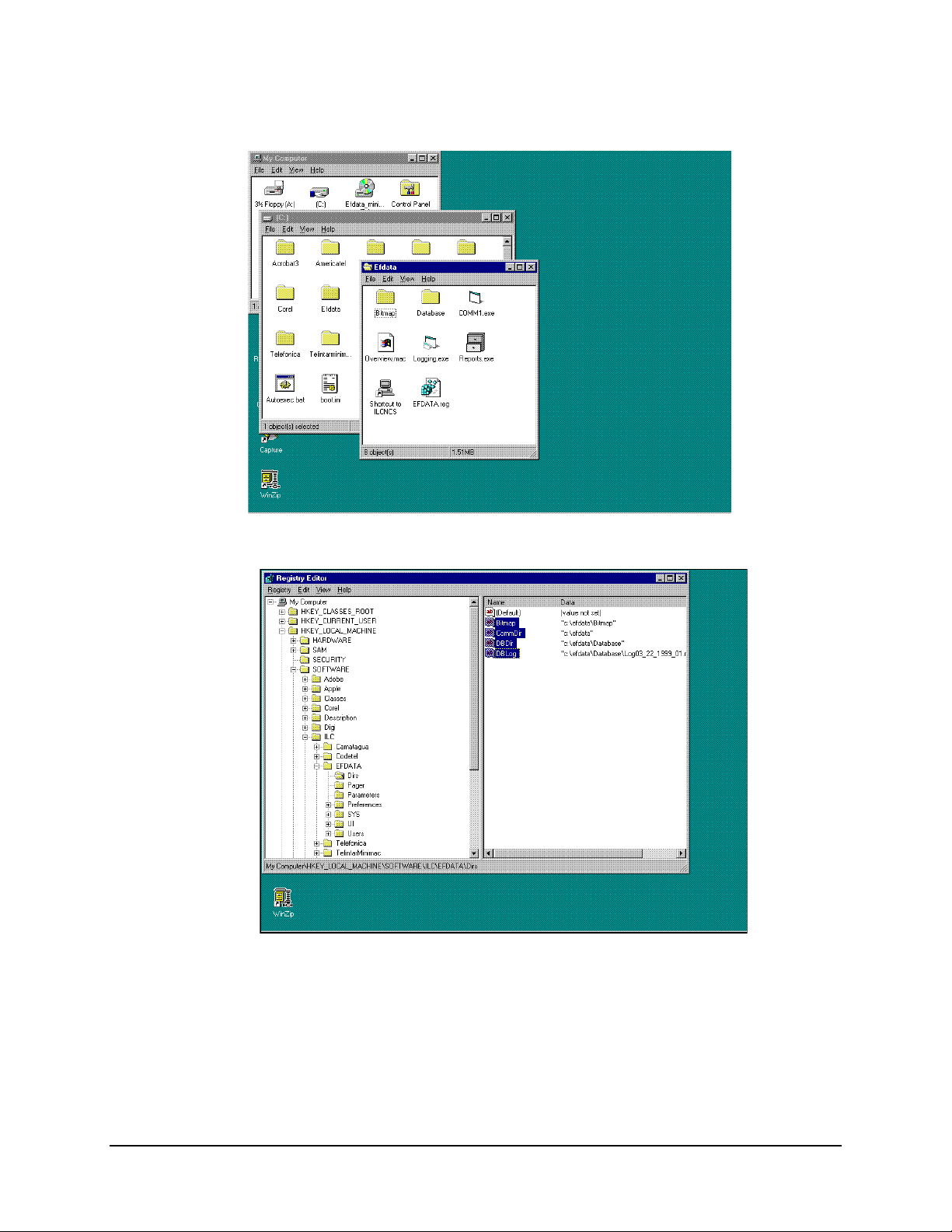
See Figure B-2
Go to: DOS Prompt
Type: REGEDIT
Path: HKEY\LOCALMACHINE\SOFTWARE\
ILC\ADAPTIVE BROAD BAND\SYS
Computer0 = MiniMAC
Verify TCP/IP Address and list in Host File. (Refer
to Appendix A, Host File.)
Return to create file folders and repeat procedure.
(see Figures B-3 and B-4
1. Disable Hyperterm or Commtest.exe.
2. Reinstall port expanders.
3. Verify hardware key on LPT1.
4. Install from CD.
)
B–2 Rev. 0
Page 18
MiniMAC Rack Management System Troubleshooting
Figure B-1. Computer Name, Defined in Windows NT Setup
Figure B-2. Path to Computer Name in Registry Editor
Rev. 0
B–3
Page 19
Troubleshooting MiniMAC Rack Management System
Figure B-3. Path to BITMAP and DATABASE File Folders
Figure B-4. Path to Registry Edit Directories
From the Registry Editor, DIRS File Folder; verify the path of the highlighted lines to the
files and folders in the site file folder. If any of the files are missing or the file folders are
misspelled, correct the anomaly. Refer to Chapter 3, Create New File Folder for
Customer Site.
B–4 Rev. 0
Page 20

Data MiniMAC Rack Management System
A.1 Windows NT
The version number corresponding with this manual is: 3.4.48
A.1.1 Computer Configuration
Refer to Table A-1 for procedures applying to the operating environment for the
MiniMAC.
Table A-1. Computer Configuration
Command Response
Enter Computer Name HPVECTRA or MiniMAC
Password ilc (lower case)
Connect to Network (Enable) NETWORK (using loopback adapter)
Select Network Adapter MS LOOPBACK ADAPTER (s
Select Protocols TCP/IP
REMOTE ACCESS
NET BEUI
ee Figures A-1)
(see Figures A-2)
A–2 Rev. 0
Page 21
MiniMAC Rack Management System Data
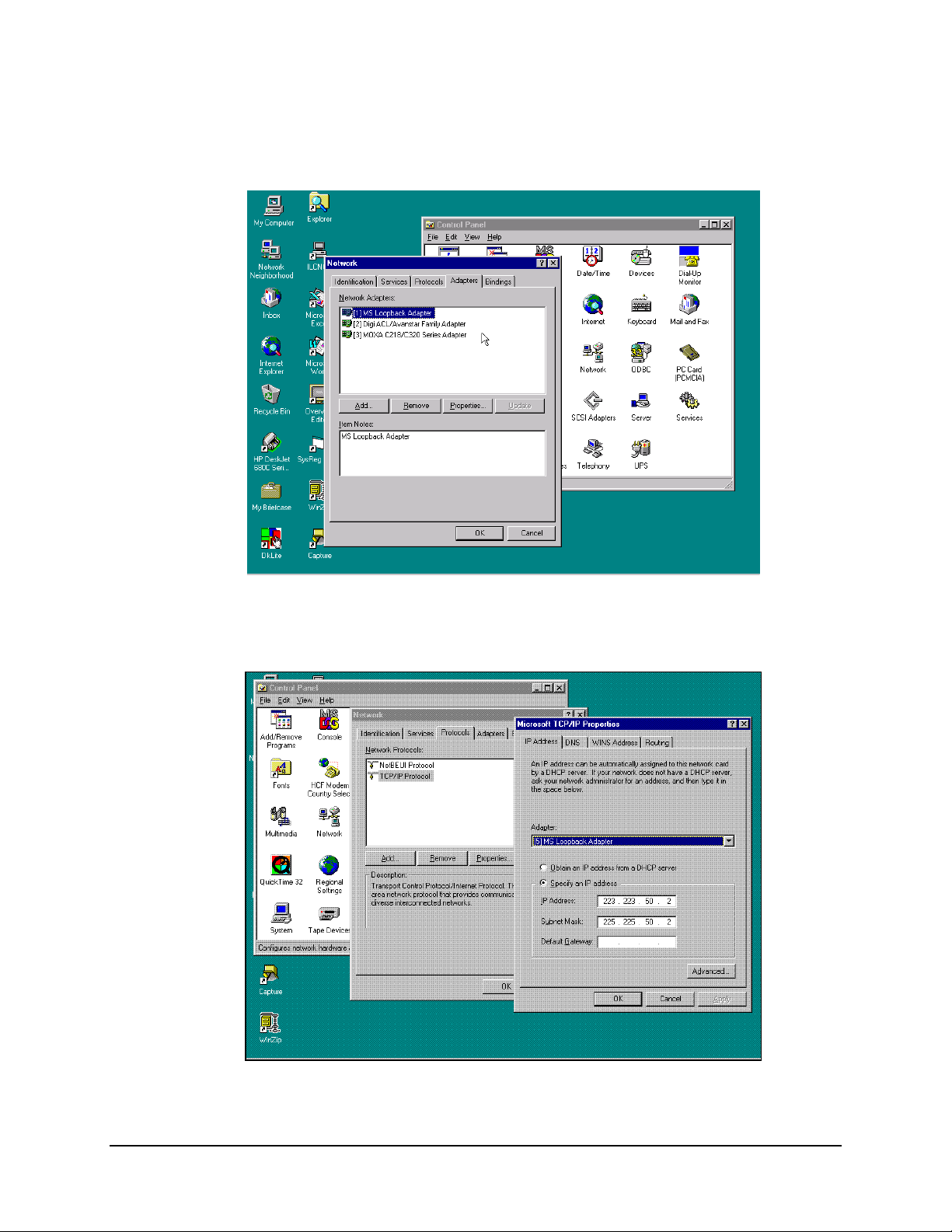
When configuring Windows NT, connect to the the network using the MS Loopback
Adapter.
Figure A-1. Select Network Adapter
During Windows NT configuration, load the TCP/IP Protocol and configure.
Figure A-2. TCP/IP Protocol Properties
Rev. 0 A–3
Page 22
Data MiniMAC Rack Management System
A.2 Path to Windows NT Diagnostics
Note:
Windows NT Diagnostics can be a valuable tool during computer setup.
Path: Start\Programs\Administrative Tools\Windows NT Diagnostics
A–4 Rev. 0
Page 23
MiniMAC Rack Management System Data
A.2.1 Windows NT Diagnostics
Note: The computer name is in Windows NT diagnostic header; MINIMAC
Open: Resources File Folder.
Rev. 0 A–5
Page 24
Data MiniMAC Rack Management System
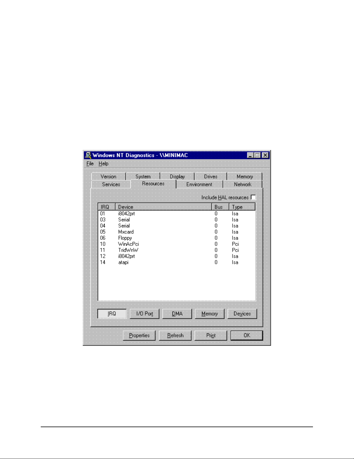
A.2.2 Windows NT Diagnostics – IRQ
Note:
All devices requiring an IRQ will be displayed with the active IRQ shown in the
first column. Plug and play devices will automatically be selected upon installation. Port
expander cards (ACL or MOXA) must have jumpers or switches set on the card.
Select an unused IRQ for configuring the port expander card.
Note:
All configuration information on the setup is stored in a file titled:
IP CONFIGURATION.TXT.
A–6 Rev. 0
Page 25
MiniMAC Rack Management System Data
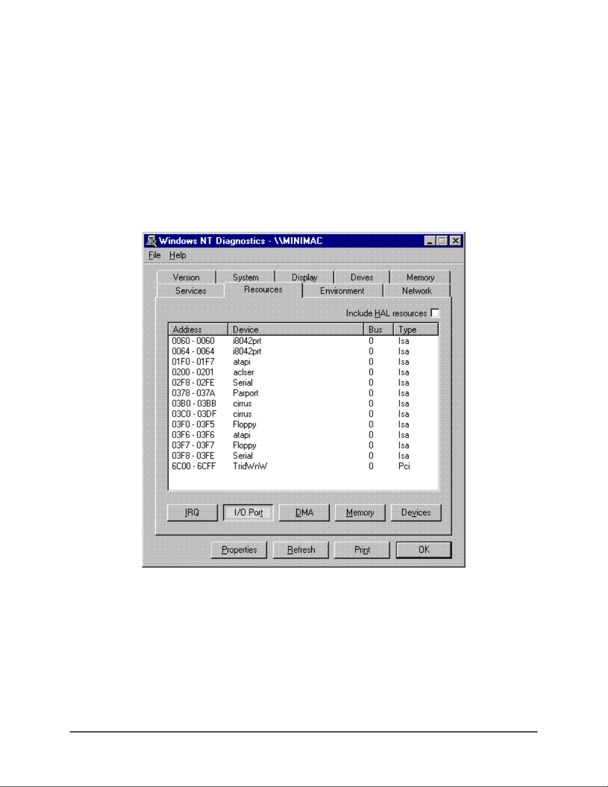
A.2.3 Windows NT Diagnostics – I/O Ports
I/O port addressing will be automatic for plug and play devices. Port expander cars will
have jumpers, switches, or configuration settings in the setup (refer to Section 3.3). Select
an address that is not in use.
Note:
These are Windows NT functions. For additional information, refer to the
Windows NT manual.
Rev. 0 A–7
Page 26
Data MiniMAC Rack Management System
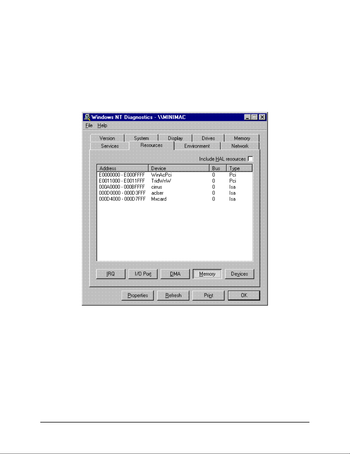
A.2.4 Windows NT Diagnostics – Memory Allocation
Memory allocation also will be set automatically for plug and play devices. Memory for
port expander cards must be configured in the setup process (refer to Section 3.3). Select
a memory allocation that is not in use.
A–8 Rev. 0
Page 27
MiniMAC Rack Management System Data
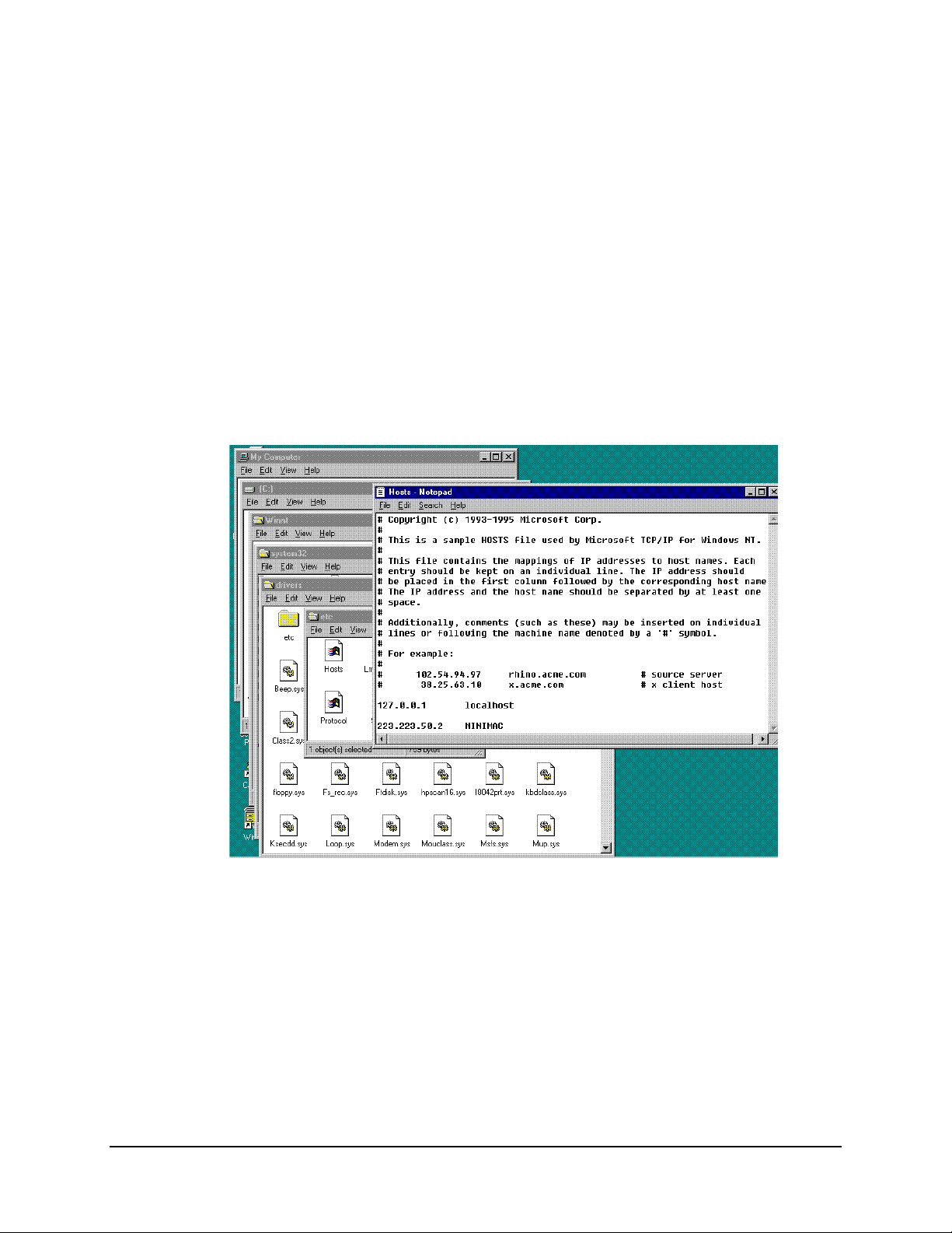
A.2.5 Host File
The HOST File is used by Microsoft TCP/IP for windows NT. It contains the mapping
of IP addresses to host names. If UINETMAN does not run in the services, it may be
necessary to add a new line to the HOST file. The path to the HOST file is:
Path: My Computer\C:\Winnt\system32\drivers\etc
Open the file labeled Hosts with the Notepad Program. Refer to Section A.1.1,
Figure A-3, the TCP/IP Address for the computer is located in the IP Address window.
The IP address and computer name should be added to the end of the host file.
Note:
After adding the new line as shown, save the Host File prior to closing.
Rev. 0 A–9
Page 28
Data MiniMAC Rack Management System
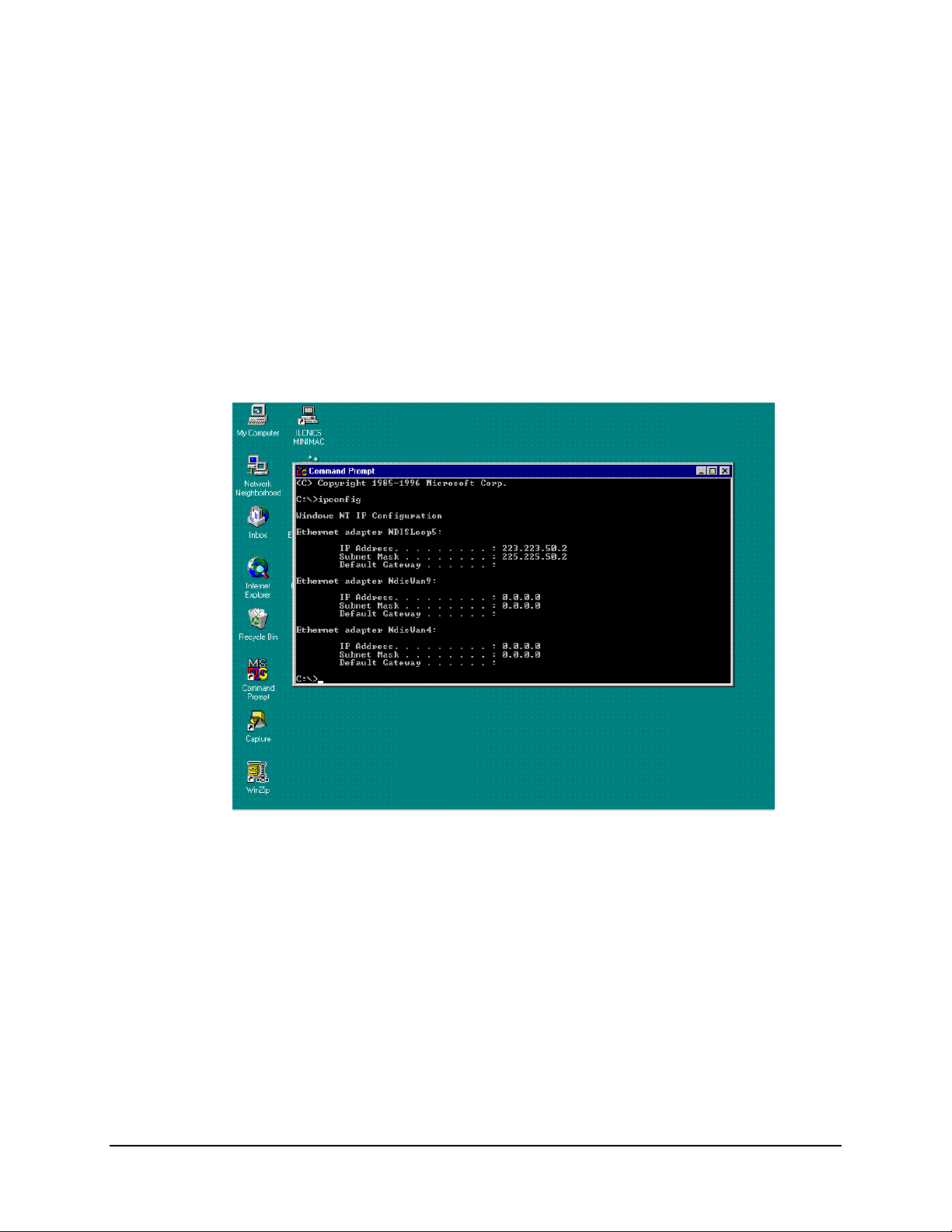
A.2.6 IP Configuration Command
Alternate Method: To identify the I P address of the com puter, use the Win dows NT
command:
From a DOS prompt window type: ipconfig
The response will be the Windows NT IP Configuration for all Ethernet adapters installed
in the computer. The NDISLOOPS adapter is used for the TCP/IP address in our
configuration. The IP address (top line) can be typed into the HOST File for mapping to
the computer.
A–10 Rev. 0
Page 29
MiniMAC Rack Management System Data
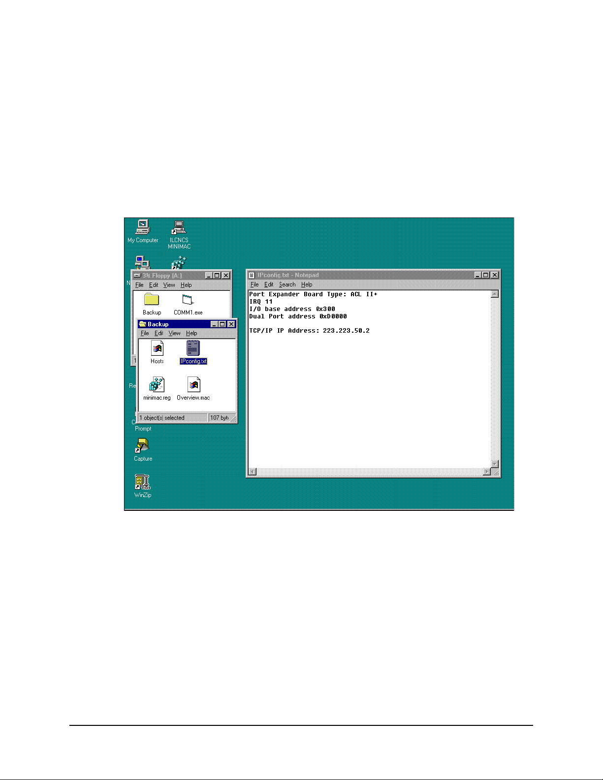
A.2.7 IP Configuration.Txt File
The IP Configuration.Txt file is a very useful tool for installation. The file is supplied on
a floppy disk with backup file information. The path is:
My Computer\A\Backup\
Open the file called Ipconfig.Txt
All the configuration information concerning the installed port expander card will be
displayed. The jumper and switch setup for the IRQ and base address will be listed.
Rev. 0 A–11
Page 30
Data MiniMAC Rack Management System
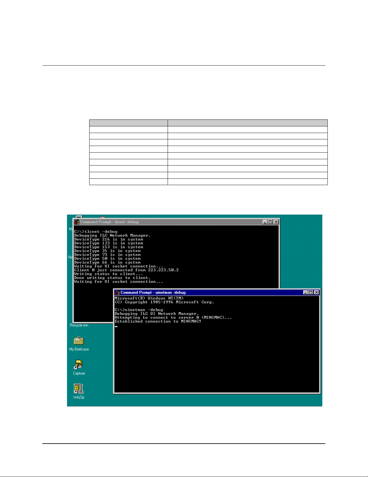
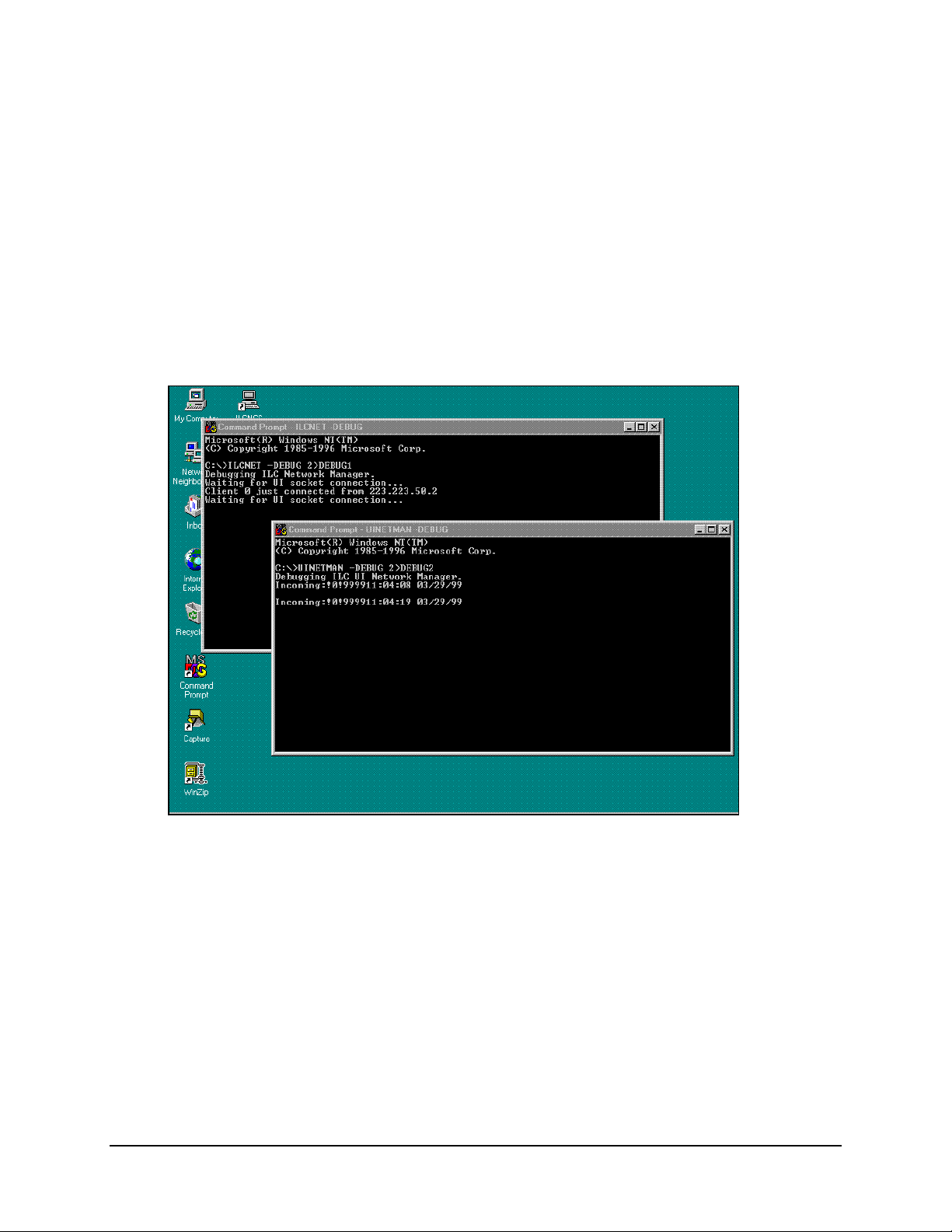
A.3 Debugging the Services
When necessary to troubleshoot the MiniMAC program, use the DEBUG command.
Perform the following:
Command Response
Open: CONTROL PANEL
Go to: SERVICES
Select: ILC NETWORK MANAGER and STOP SERVICE
Select: UINETWORK MANAGER and STOP SERVICE
Close: NETWORK Window
Close: CONTROL PANEL Window
Open DOS Prompt: Type: ilcnet -debug
Open DOS Prompt: Type: UINETMAN -debug
Start MiniMAC Program
When an error occurs, it will be displayed in the debug window.
A–12 Rev. 0
Page 31
MiniMAC Rack Management System Data
A.3.1 Saving Debug to a File
For customer support to evaluate the problem, the debug information must be written to a
file. This makes it possible to e-mail the data to Adaptive Broadband.
Alternate Method: Type the following command from the Command Prompt:
Ilcnet –Debug 2>debug1
Debug1 will be the name of the file that debug will store information.
Rev. 0 A–13
Page 32

Data MiniMAC Rack Management System
When a failure occurs, close all tasks, including the Debug Command using the Task Manager.
Open the Debug1 file with Notepad.
This information can be used for troubleshooting the system.
A–14 Rev. 0
Page 33

MiniMAC Rack Management System Data
A.4 Remote Access Administrator
Note:
When Adaptive Broadband Customer Support has determined that it is necessary
for Remote Dial In Access for troubleshooting purposes, the Remote Access Server must
be started.
This feature can only be used if a modem is installed on the MiniMAC CPU.
A.4.1 Open Remote Access Administrator
Path: Start\Programs\Administrative Tools\Remote Access Admin
Rev. 0 A–15
Page 34

Data MiniMAC Rack Management System
A.4.2 Grant User Permission
Observe path grant user permission as follows:
Command Response
Click on Start\Programs
Click on ADMINISTRATIVE TOOLS
Click on REMOTE ACCESS ADMIN
Click on USERS
Click on PERMISSIONS
Select ADMINISTRATOR
Click on GRANT DIALIN PERMISSION TO USER
Click on GRANT ALL
Click on YES
A–16 Rev. 0
Page 35
MiniMAC Rack Management System Data
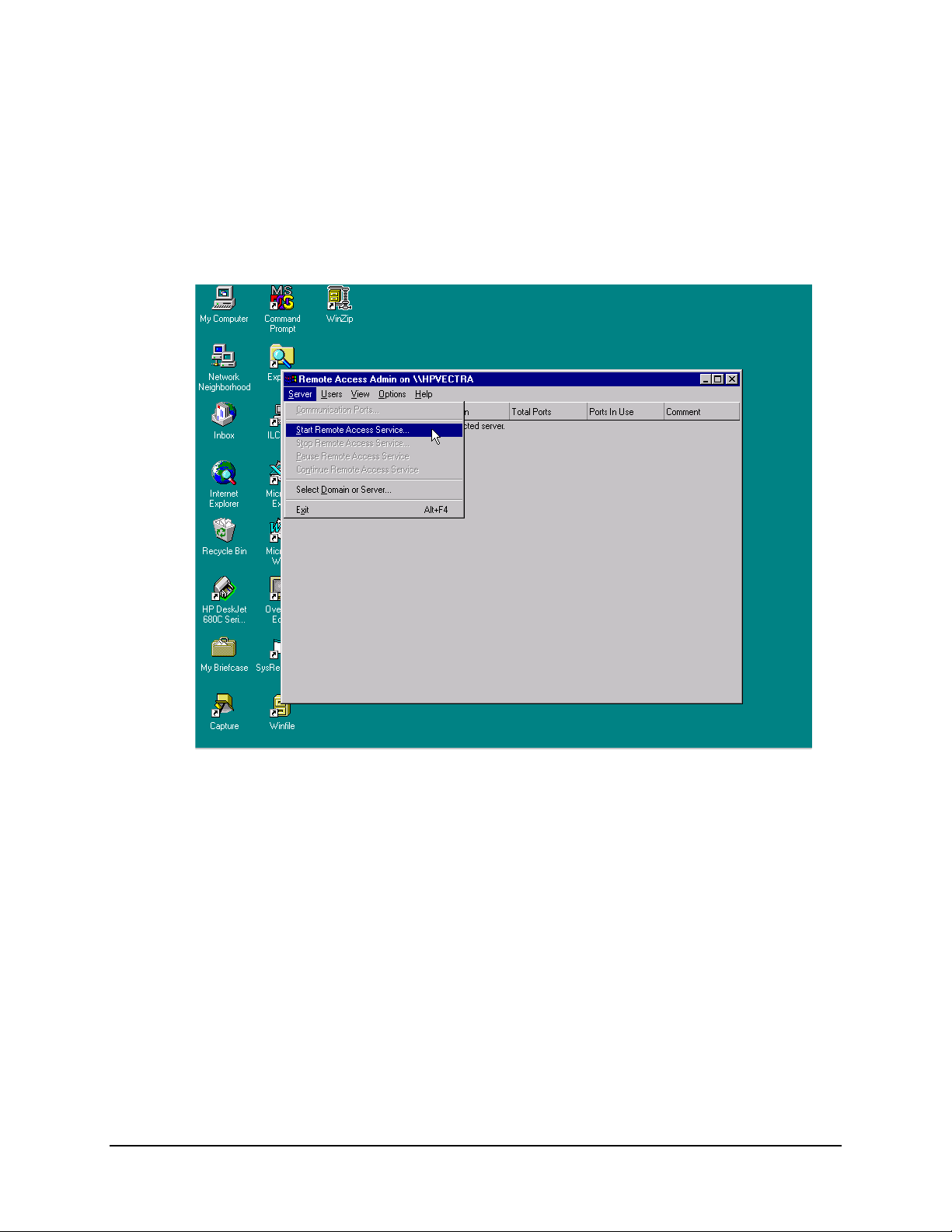
A.4.3 Starting Remote Access Service
To start the Remote Access Service, select Server and click on Start Remote Access
Service.
Rev. 0 A–17
Page 36
Data MiniMAC Rack Management System
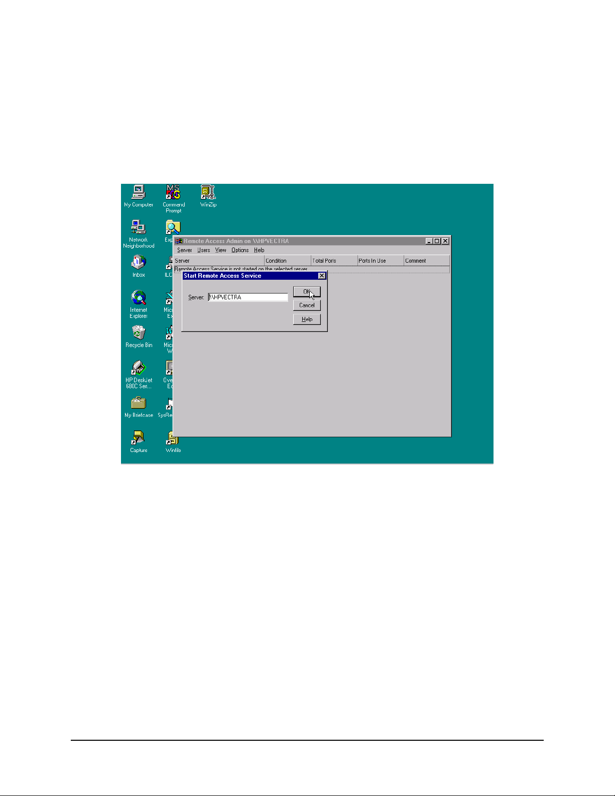
A.4.4 Verfy Computer System Name
Verify computer name, if satisfactory, click on: OK
A–18 Rev. 0
Page 37

MiniMAC Rack Management System Data
A.4.5 Attempt to Start Remote Access Administrator
The Service Control window will be displayed after computer name has been verified.
When Remote Access Server is operating properly the condition will be Running.
Rev. 0 A–19
Page 38

Data MiniMAC Rack Management System
A.4.6 Dealing with Errors
If the Remote Access Services cannot start, there will be an error message displayed. To
determine the cause, check the EVENT Log on the computer for details.
A–20 Rev. 0
Page 39

MiniMAC Rack Management System Data
A.4.7 Path to Event Viewer
Path: Start\Administrative Tools\Event Viewer
Rev. 0 A–21
Page 40

Data MiniMAC Rack Management System
A.4.8 View the System Log
Event Viewer will display all events that occurred by date and time, source, category,
event number, user, and the computer name.
Proper operation will display a BLUE ICON on the left. Errors or failures will display a
RED ICON to the left of the event.
The log can display system information or application information. The currently
displayed log is noted in the header of the EVENT VIEWER window.
Find the most current Remote Access Source that has an error and highlight.
A–22 Rev. 0
Page 41

MiniMAC Rack Management System Data
A.4.8.1 View Event Detail Information
Highlight the event that will be read and double-click.
The event details will be displayed in the EVENT DETAIL window. This message
displays that the RAS has not been configured.
Close the Event Detail window and Event Viewer.
Rev. 0 A–23
Page 42
Data MiniMAC Rack Management System
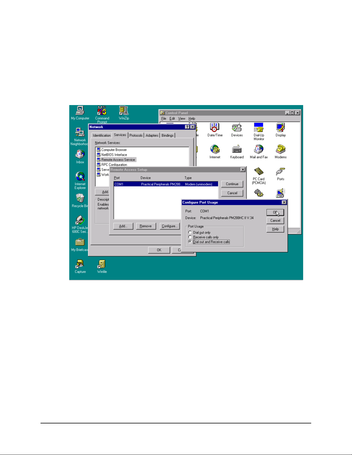
A.4.9 Setting Up the Dial in Port Usage
Path: Start\Settings\Control Panel\Network\Services\Remote Acccess
Service\Properties\Configure.
From the Configure Port Usage window select Dial Out and Receive Calls.
Click on; OK.
A–24 Rev. 0
Page 43

MiniMAC Rack Management System Data
A.4.10 Checking the RAS Server TCP/IP Address
From the Remote Access Setup window, click on: Network. From the Network
Configuration window, verify TCP/IP is checked in both locations and click on
Configure TCP/IP.
Type the TCP/IP address that was determined in the protocol setup. This computer’s
TCP/IP address is 223:223.50.2. The end address is 225.225.50.2.
After typing in the correct address click on OK. In the Network Configuration window
Click on: OK.
From the Remote Access Setup window, click on: Continue.
From the Network window, Click on: OK.
Rev. 0 A–25
Page 44

Data MiniMAC Rack Management System
A.4.11 Restarting the Computer
The computer will save the network settings to the Registry Editor. Shut down the
computer before the settings can take effect. Click on Yes to restart the computer.
A–26 Rev. 0
Page 45

Overview Editor Program MiniMAC Rack Management System
7.1 ILC Overview Editor Program
Path: Start\Programs\ILC Overview Editor
Select Adaptive Broadband or current SITE user
Click on: OK
Note:
When there are more than one-configuration choices in the Drop Down Menu;
Click on: Make This the Active Configuration
This will update the Registry Editor to always RUN the selected configuration.
7–2 Rev. 0
Page 46
MiniMAC Rack Management System Overview Editor Program
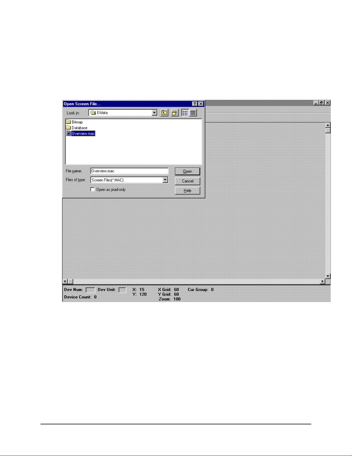
7.1.1 Opening the Overview.Mac File
Select Overview.Mac
Click on: OPEN
Rev. 0 7–3
Page 47
Overview Editor Program MiniMAC Rack Management System
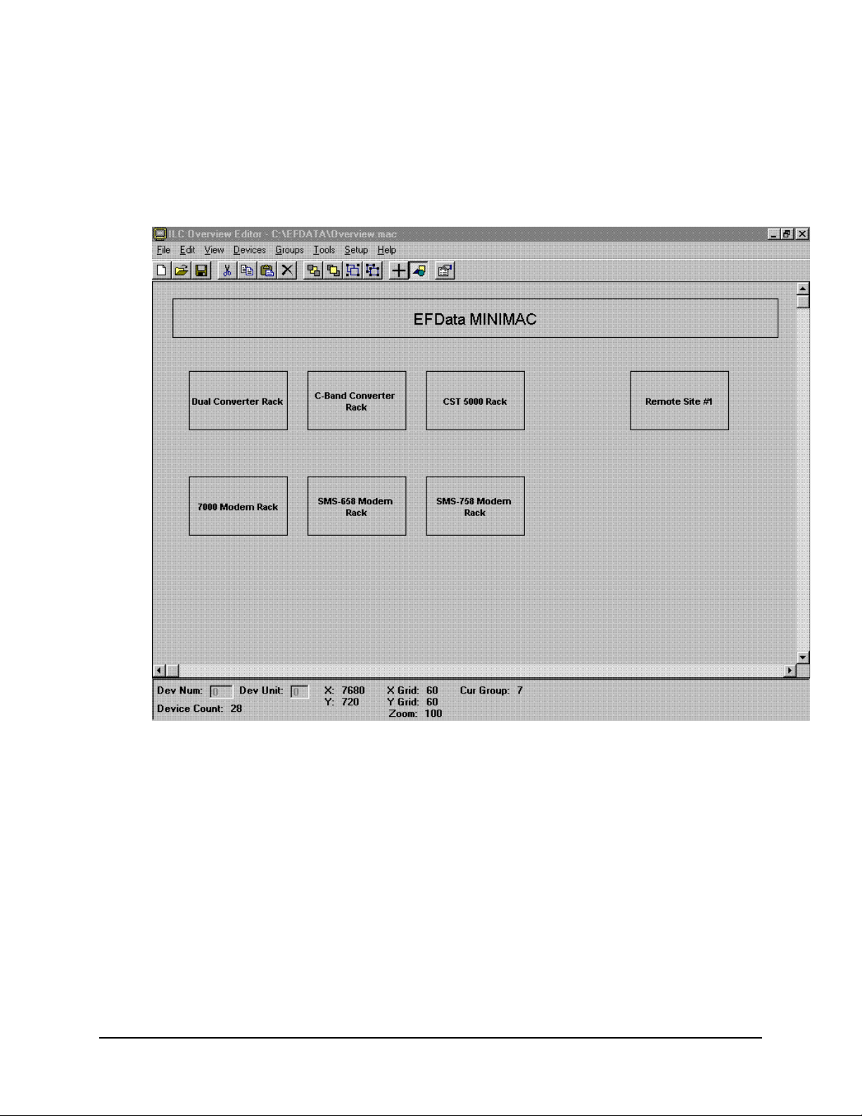
7.1.2 Viewing the Overview Screen
The current Overview Screen will be displayed.
7–4 Rev. 0
Page 48

MiniMAC Rack Management System Overview Editor Program
7.2 Editing Item Properties
Double-click a specific item or group to be edited. The item properties window will
appear. From this window the user can change:
• Fill Color
• Draw Color
• Insert an Image into the box
• Change the Label Properties, including:
• Color
• Font
• Alignment of the Label
When completed, click on OK.
Rev. 0 7–5
Page 49

Overview Editor Program MiniMAC Rack Management System
7.3 Viewing
7.3.1 Viewing Selected Groups
Click on: The desired group to be viewed
Go to: GROUPS (located in the pull-down menu)
Select: View Selected
7–6 Rev. 0
Page 50

MiniMAC Rack Management System Overview Editor Program
7.3.2 Viewing Remote Site
To view the equipment at the remote site, perform the following:
Command Response
Click on REMOTE SITE #1 GROUP
Go to GROUPS
Select VIEW SELECTED
The REMOTE SITE #1 Group Window will appear on the screen.
Rev. 0 7–7
Page 51

Overview Editor Program MiniMAC Rack Management System
7.3.3 Creating a New Group
If new REMOTE SITES or NEW GROUPS need to be added to the MiniMAC System,
the user has that ability. To create a NEW GROUP, use the pointing tool to draw a new
box as shown in white. Ensure the object is highlighted, go to GROUPS and click on
CREATE. The new group will be opened and the user can load devices.
7–8 Rev. 0
Page 52
MiniMAC Rack Management System Overview Editor Program
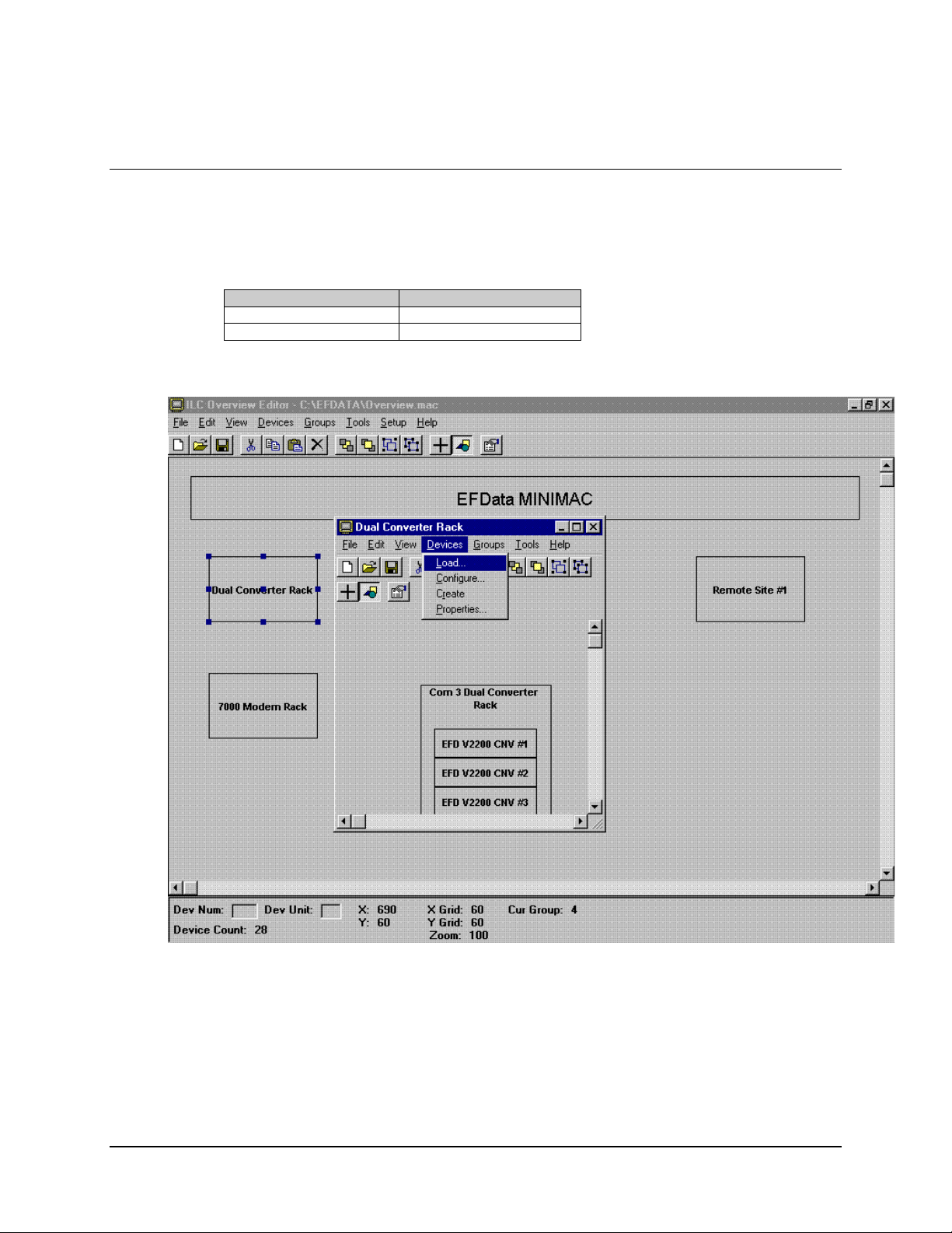
7.4 Loading New Devices
To load new devices to a group, go to the drop-down menu in the GROUP window and
perform the following:
Command Response
Select DEVICES
Click on LOAD
Rev. 0 7–9
Page 53

Overview Editor Program MiniMAC Rack Management System
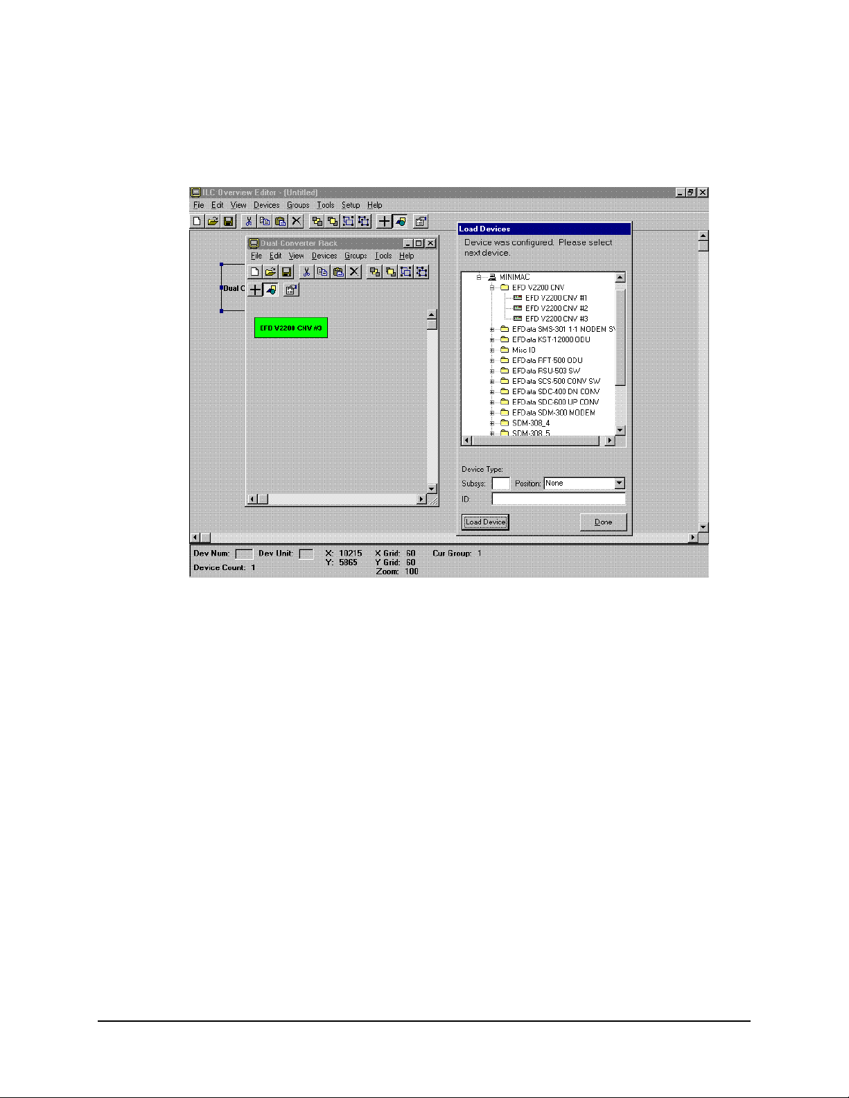
7.4.1 Selectin g and Configuring New Devices
From the LOAD DEVICES window, open the MiniMAC folder to reveal the available
devices. To select and configure a new device, perform the following:
Command Response
Select DEVICE TO BE ADDED
Select POSITION
Click on LOAD DEVICE
7–10 Rev. 0
Page 54
MiniMAC Rack Management System Overview Editor Program
Note:
The device will appear in the selected group. Place device in the proper position.
When all devices have been loaded, click on: DONE in the LOAD DEVICES window.
Rev. 0 7–11
Page 55

Overview Editor Program MiniMAC Rack Management System
7.5 Saving Changes to the Overview.Mac File
After all devices have been selected;
Save: Overview.Mac file
Restart the computer.
7–12 Rev. 0
Page 56

System Setup Program MiniMAC Rack Management System
6.1 System Setup Program
Note:
Prior to running System Setup, close the MiniMAC Program.
Path: Start\Programs\ILC System Setup
Select EFData or current SITE name; Click on OK.
6–2 Rev. 0
Page 57

MiniMAC Rack Management System System Setup Program
6.2 Selecting Number of Computers
Note:
Most systems only have one computer. If a system has more than one computer,
then enter the number of computers and click NEXT.
Rev. 0 6–3
Page 58

System Setup Program MiniMAC Rack Management System
6.2.1 Entering the Computer Name
Notes:
1. The name of the customer computer can be located at:
Start\Programs\Administrative Tools\Windows NT Diagnostics
2. The name of the computer will be across the banner at the top.
3. Type the computer name and click NEXT.
6–4 Rev. 0
Page 59

MiniMAC Rack Management System System Setup Program
6.3 Setting Up the COMM Ports
Select number of COMM Ports, enumerate starting at COMM 3.
Select the following for each COMM port:
• Baud Rate
• Parity
• Data Bit/s
• Stop Bit/s
Click on: NEXT.
Rev. 0 6–5
Page 60

System Setup Program MiniMAC Rack Management System
6.4 Selecting COMM Ports for Device Setup
Select a COMM port for adding devices.
6–6 Rev. 0
Page 61
MiniMAC Rack Management System System Setup Program
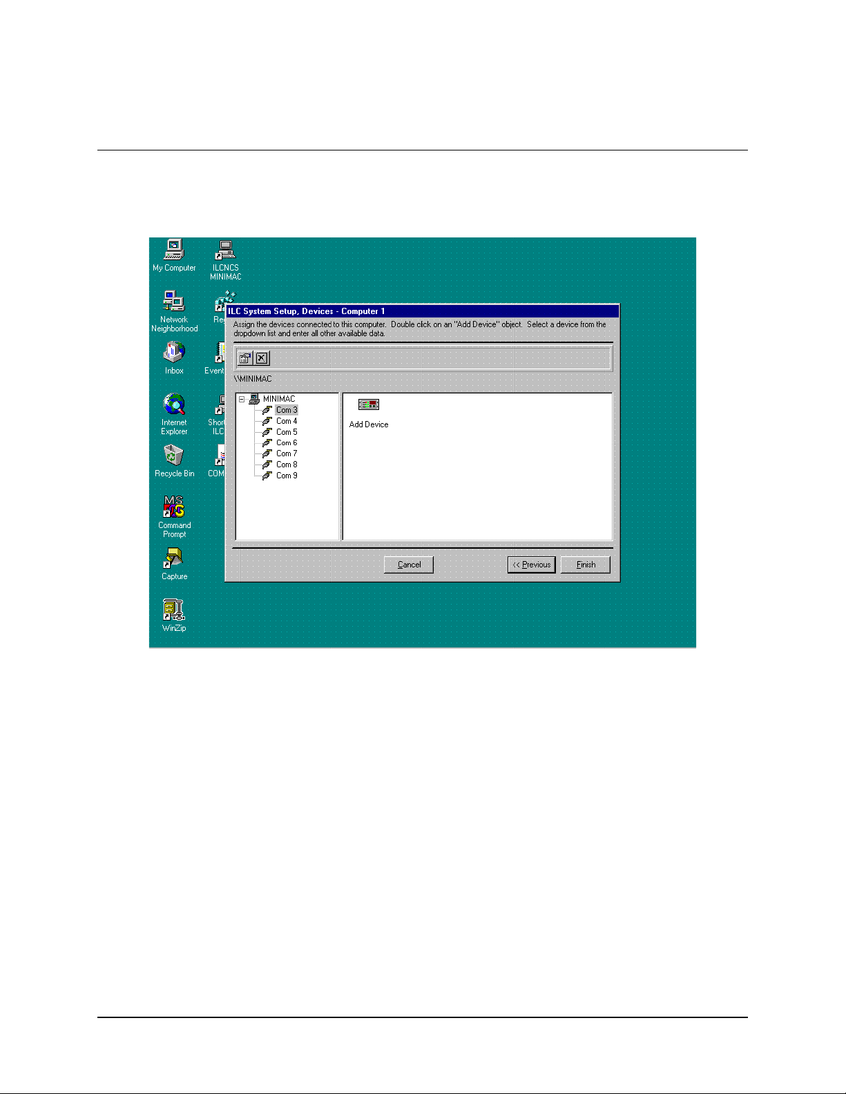
6.5 Adding a New Device
Click on: ADD DEVICE
Rev. 0 6–7
Page 62
System Setup Program MiniMAC Rack Management System
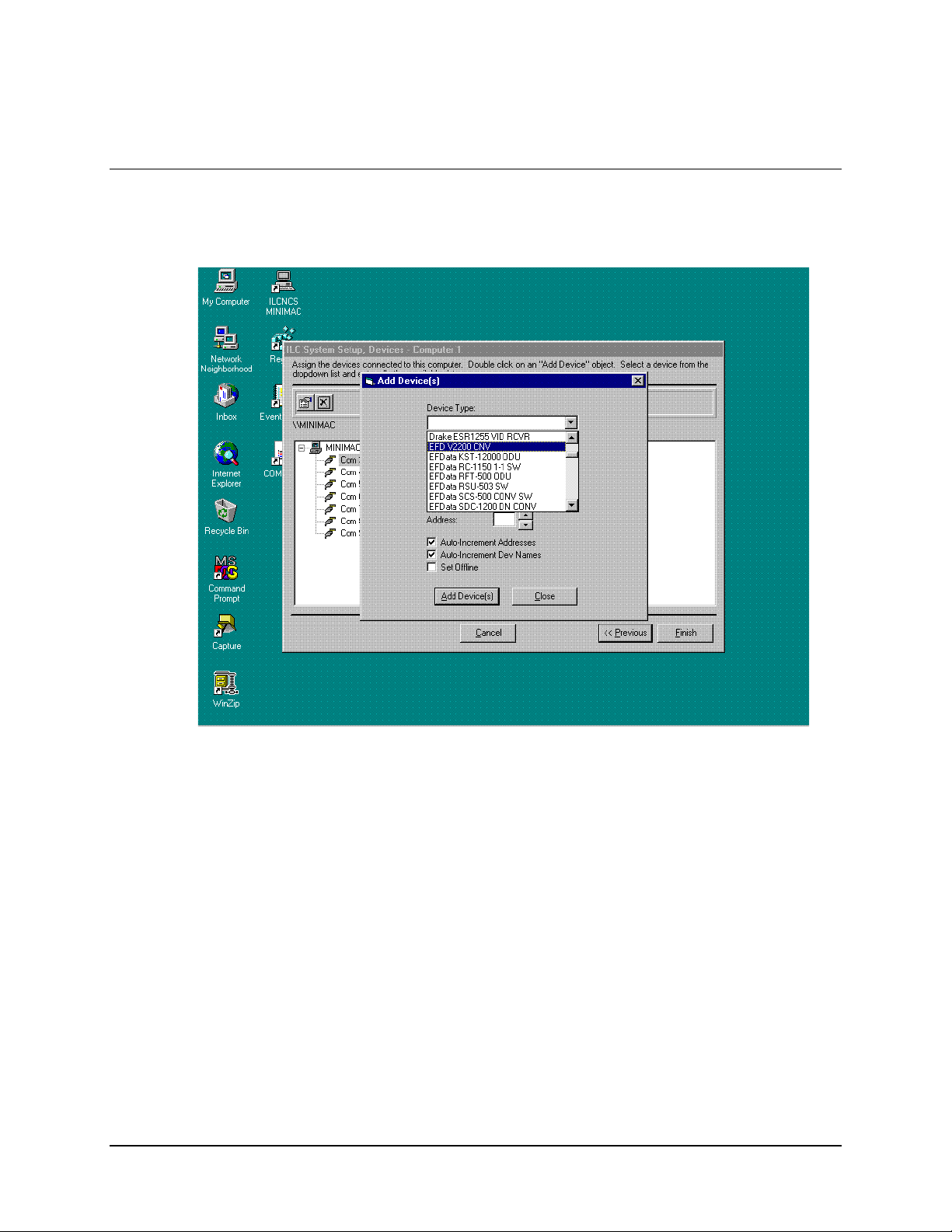
6.6 Selecting a New Device Type from Device List
Select the required EFData device from the Device List.
6–8 Rev. 0
Page 63
MiniMAC Rack Management System System Setup Program
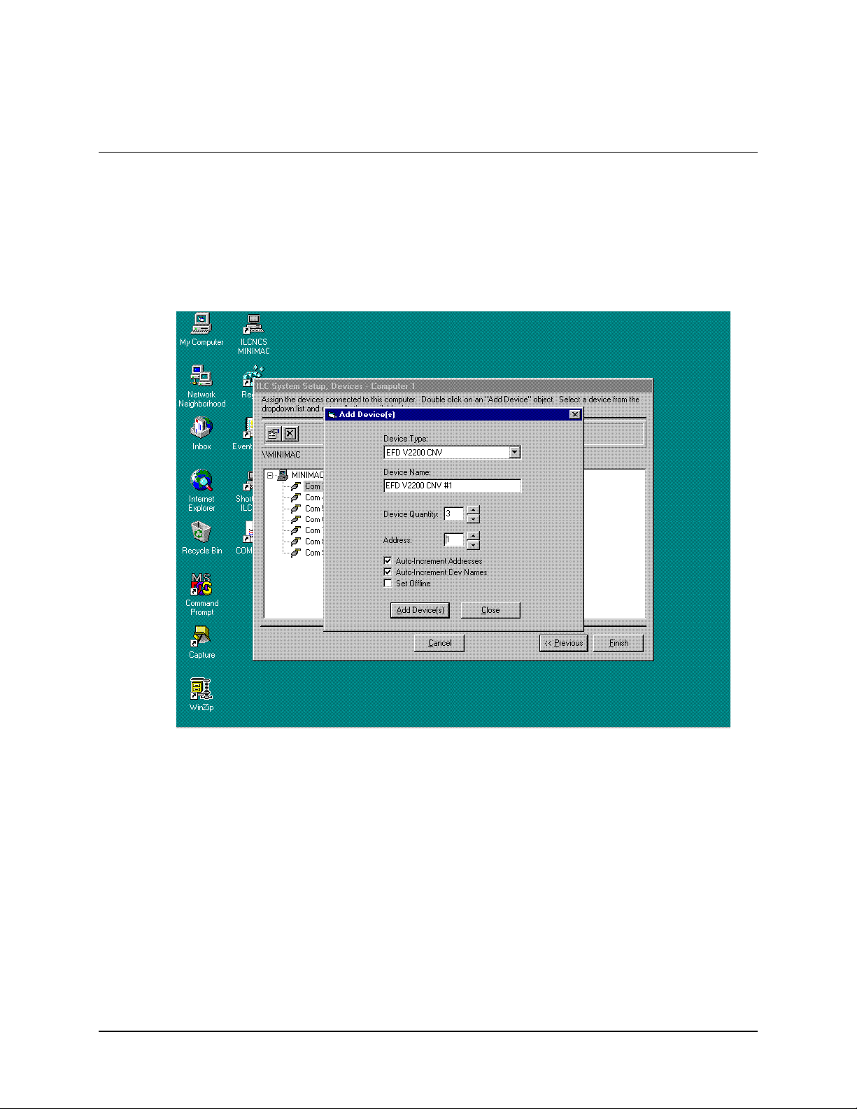
6.7 Configuring and Adding the New Device Type
Select device quantity to add to COMM port. Select the Device Address.
Click on: ADD DEVICE (S)
Note:
Continue to add devices until all Device Types have been added to each
COMM Port.
Rev. 0 6–9
Page 64

System Setup Program MiniMAC Rack Management System
6.8 Creating an EXCEL Spreadsheet
When all device types have been added to each COMM port:
Click on: FINISH
A prompt will appear asking to create an EXCEL spreadsheet for this configuration.
• If EXCEL is available, Click on: YES
• If EXCEL is not available, Click on: NO
6–10 Rev. 0
Page 65

MiniMAC Rack Management System System Setup Program
6.9 Updating the System Registry
Upon completion, the system Registry Editor has been successfully configured.
Restart the computer.
Note:
It is recommended to export a copy of the Registry File to a backup location after
running the System Setup Program.
Rev. 0 6–11
Page 66

System Setup Program MiniMAC Rack Management System
This page is intentionally left blank.
6–12 Rev. 0
Page 67

Service Pack MiniMAC Rack Management System
5.1 Path to Service Pack
Verify path to the Service Pack:
Path: My Computer\D:Adaptive Broadband_MiniMAC\MiniMAC\Tools\ntsp4
Run: ntsp4i.exe
5-2 Rev. 0
Page 68
MiniMAC Rack Management System Service Pack
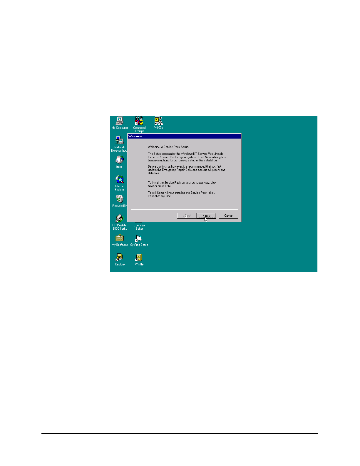
5.2 Service Pack
Read: Welcome to Service Pack.
Click on: NEXT
Rev. 0 5-3
Page 69
Service Pack MiniMAC Rack Management System
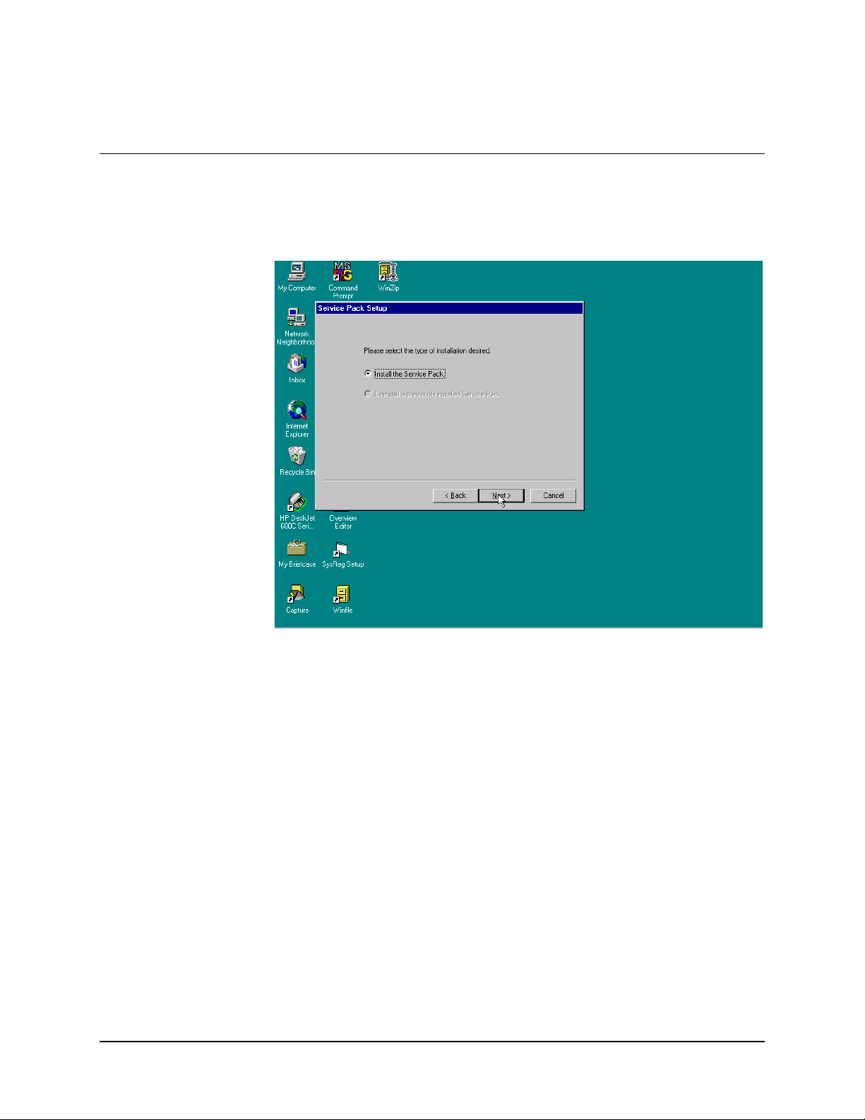
5.3 Service Pack Installation
Select the type of required installation.
5-4 Rev. 0
Page 70

MiniMAC Rack Management System Service Pack
5.3.1.1 Uninstall Options
The Uninstall Options allows the user to create an Uninstall directory for the Service
Pack.
Command Response
Enable Yes (Allows user to create an Unin stall directory)
No (Allows the user to decline the offer)
Click on NEXT
Rev. 0 5-5
Page 71

Service Pack MiniMAC Rack Management System
5.3.1.2 Complete Installation
User must decide to finish the installation or exit the program at this time.
Command Response
Install Service Pack
Click on: Finish or press <ENTER>
Exit Setup without installing Service Pack
Click on: Cancel (Cancels installation of Service Pack and removes
temporary files.)
5-6 Rev. 0
Page 72

MiniMAC Rack Management System Service Pack
5.4 Restarting the Computer
Windows NT has been updated and will prompt the user to restart the computer at this
time. Click on: OK
Rev. 0 5-7
Page 73

Service Pack MiniMAC Rack Management System
This page is intentionally left blank.
5-8 Rev. 0
Page 74

Registry Editor MiniMAC Rack Management System
4.1 Path to Command Prompt
Path to Registry Editor:
Start:\Programs\Command Prompt
4.2 Opening the Registry Editor
To permit access to the REGISTRY EIDTOR, perform the following:
Type: REGEDIT
4–2 Rev. 0
Page 75

MiniMAC Rack Management System Registry Editor
4.2.1 Path to the HOTKEY and COMM Ports
To view the COMM ports, perform the following:
Command Response
Go to HKEY_LOCAL MACHINE
Go to SOFTWARE
Go to ILC
Go to EFData
Go to SYS
Go to Computer0
Go to COMM
Open COMM F ile Folder
Note:
Observe the last line on the right-hand side. The number of ports in
this system is 7.
Rev. 0 4–3
Page 76

Registry Editor MiniMAC Rack Management System
Open PORT 0 file folder
Notes:
1. Observe the right column, information concerning each particular port is displayed. This
port is ComPort3. The ComPort is OPEN (ACTIVE). The ComPort SETTING
“9600,E,7,2” is:
•
Baud Rate = 9600 kbit/s
•
Parity = Even
•
7 data bits
•
2 stop bits
2. Timeout Time may be important for lower baud rate or ports that are remote sites.
Typically, for local ports, the Timeout Time is within 0 and 3 seconds. For lower baud
rate ports and remote sites, the Timeout Time is typically set within 2 to 5 seconds. For
additional information, refer to Appendix B, Troubleshooting.
4–4 Rev. 0
Page 77
MiniMAC Rack Management System Registry Editor
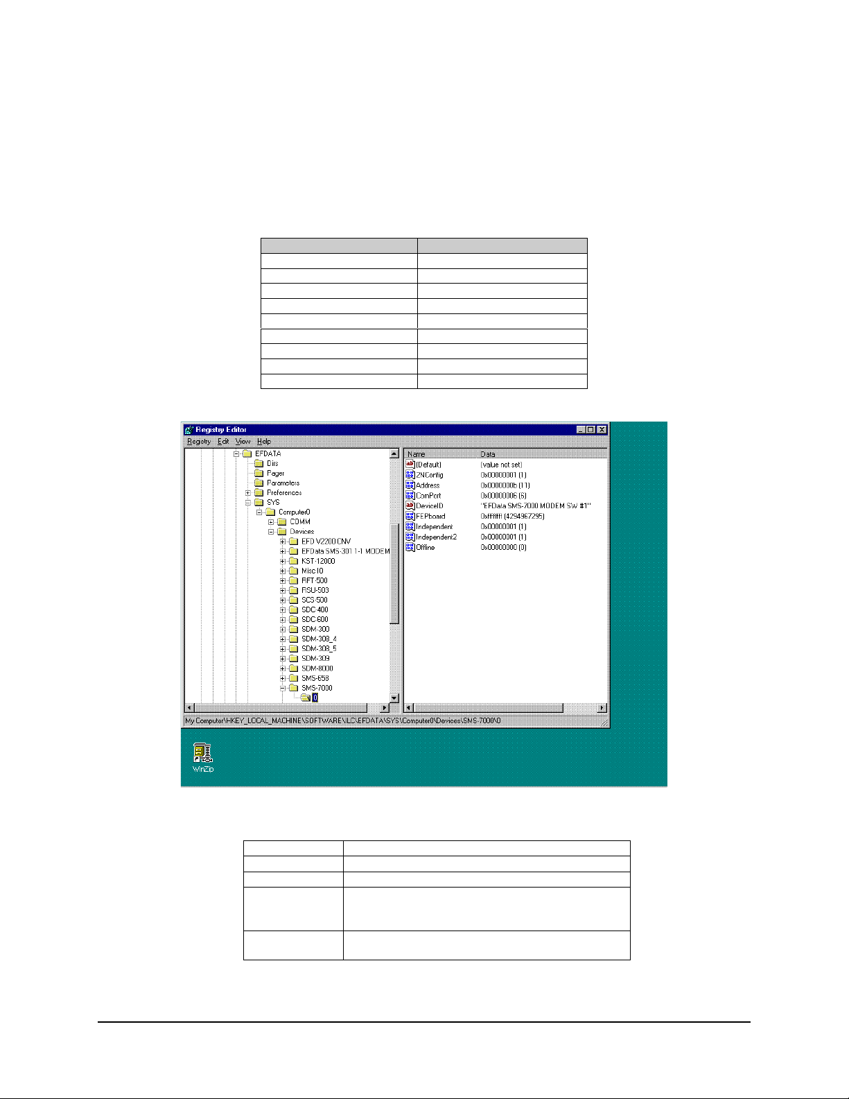
4.2.2 Path to the ILC Devices
To view the ILC Devices, perform the following:
Command Response
Go to HKEY_LOCAL MACHINE
Go to SOFTWARE
Go to ILC
Go to EFData
Go to SYS
Go to Computer # 0
Go to DEV ICES
Go to SMS-7000
Go to Folder0
Note:
The SMS-7000 Switch is:
Connected to ComPort 6
Address 11
Configured 2NConfig (2 Backups)
Device Name SMS-7000 Modem SW #1
Backup #1 is INDEPENDENT
Backup #2 is INDEPENDENT
Status ONLINE (MiniMAC is communicating or polling this
device.)
Rev. 0 4–5
Page 78
Registry Editor MiniMAC Rack Management System
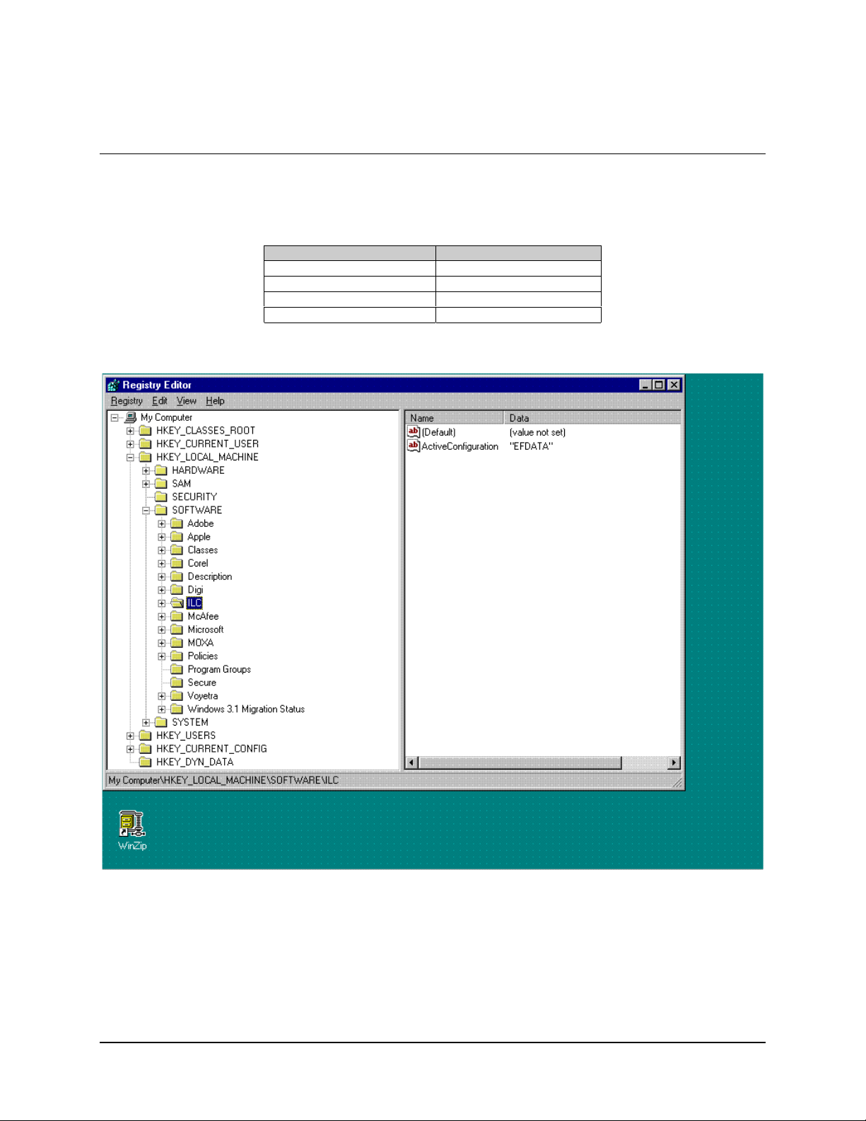
4.3 Selecting a Path to Export
To select a path to export, perform the following:
Command Response
Go to HKEY_LOCAL MACHINE
Go to SOFTWARE
Go to ILC
Highlight ILC file folder
4–6 Rev. 0
Page 79
MiniMAC Rack Management System Registry Editor
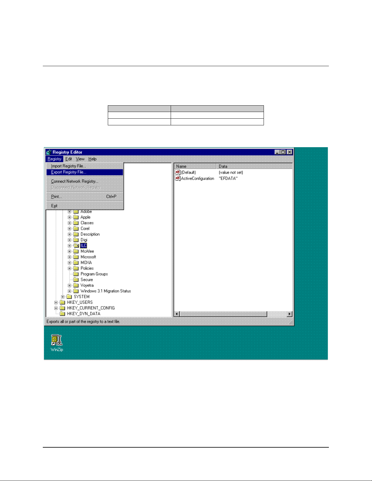
4.4 Exporting a Registry File
Perform the following to export a REGISTRY File.
Command Response
Click on REGISTRY menu
Click on EXPORT REGISTRY FILE
Rev. 0 4–7
Page 80

Registry Editor MiniMAC Rack Management System
4.4.1 Naming the Registry File
To name a REGISTRY File, perform the following:
Command Response
Click on REGISTRY menu
Click on EXPORT REGISTRY FILE
Save as Name Location
File Name Name File
Click on SAVE
Whenever the Registry Editor has been updated or modified, it is recommend
to export the new Registry File to a backup floppy. Possible anomalies may
CAUTION
occur in the program, if a backup is not performed.
4–8 Rev. 0
Page 81

MiniMAC Program MiniMAC Rack Management System
3.1 MiniMAC Program Setup
Note:
Ensure Windows NT, is installed, refer to Appendix A.
1. Install the PC board to accept the port expanders in an available 16 bit
(full-length) expansion (ISA) slot, as follows:
PC Card P/N 650111-03, Controller is for ACL Star Gate
•
PC Card C320 Control Board is for the MOXA
•
2. Install the Rainbow Hardware key at the LPT1 port of the computer.
3. Install WIN ZIP on the computer.
Note:
WIN ZIP is located in the DRIVER file folder of the MiniMAC CD-ROM.
3.2 Install SENTINAL Driver
From the MiniMAC CD prompt, run the SENTINEL program:
Go to: CD:\Site\Drivers\SENTINEL\Setupx86.exe
•
Run Setupx86.exe
•
3–2 Rev. 0
Page 82

MiniMAC Rack Management System MiniMAC Program
Install Driver as follows:
Go to: Functions
•
Click on: Install Sentinel Driver
•
Rev. 0 3–3
Page 83

MiniMAC Program MiniMAC Rack Management System
3.3 Install Port Expander Drivers
3.3.1 STAR GATE
Verify path of OEMSETUP.INF:
Record Path: C:\Site\Drivers\ACLDrivers\Version 2.0\Oemsetup.inf.
Note:
In this example, the site name is MiniMAC.
/ACL Procedures
Corel402
3–4 Rev. 0
Page 84
MiniMAC Rack Management System MiniMAC Program
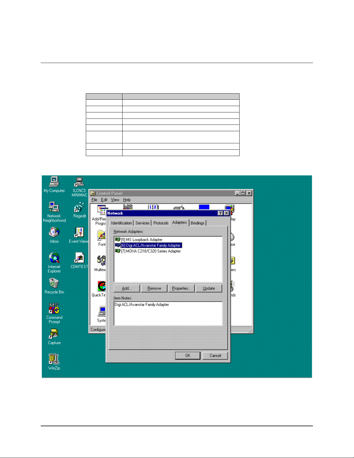
3.3.1.1 Installing Adapter Drivers
Select the adapters and install drivers, as follows:
Command Response
Go to START, Control Panel
Click on NETWORK
Select ADAPTERS
Click on ADD
Click on HAVE DISK
Type C:\Site\Drivers\ACLDrivers\Version 2.0
(as recorded in Section 3.3.1)
<ENTER>
Go to Properties
Rev. 0 3–5
Page 85

MiniMAC Program MiniMAC Rack Management System
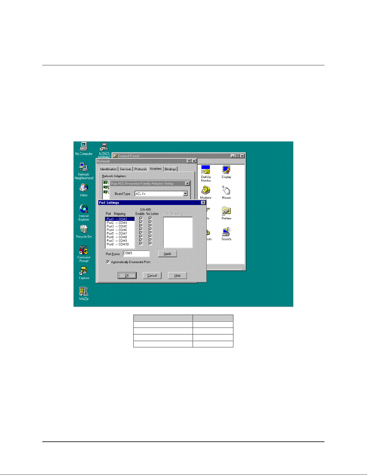
3.3.1.2 Install Properties
Select properties, as follows:
Selection Reponse
Select Board Type (ACL II+)
Select I/O Base Address 0x200
Select Dual Port Address 0xD000
Dual Size 16
No. of Ports 8
Note:
All systems will have an identification file of all system parameters.
This data is stored in: A:\B A CKUP\IP CO N FIG .TX T
3–6 Rev. 0
Page 86
MiniMAC Rack Management System MiniMAC Program
3.3.1.3 Enable Ports
Go to PORTS and check mark (!) all the NO LISTENS
Note:
The following is for a system with two boards.
Example : First PC card will be 3 – 10
Second PC card will be 11 – 18
Command Response
Click on OK
Click on OK
Click on OK
Restart Computer
Verify the COMM ports with either:
Hyperterm.Exe
Commtest. Exe
Notes:
1. Commtest.exe will run the communications port just like the MiniMAC program.
2. Hyperterm is located within the Windows NT program.
3. Commtest is located at: C:\Program Files\ILCNCS\Commtest.Exe.
Rev. 0 3–7
Page 87

MiniMAC Program MiniMAC Rack Management System
3.3.2 MOXA Procedures
Verify path to OEMSETUP.INF
Record path: CD:\MiniMAC\Drivers\Moxa\ Windows.nt
3–8 Rev. 0
Page 88

MiniMAC Rack Management System MiniMAC Program
3.3.2.1 Install MOXA Adapter Drivers
Select the adapters and install drivers, as follows:
Command Response
Go to START, Control Panel
Click on NETWORK
Select ADAPTERS
Click on ADD
Click on HAVE DISK
Type D:\Site\Drivers\MOXA\Windows.NT
(as recorded in Section 3.3.2)
<ENTER>
Go to PROPERTIES
Select PROPERTIES
Rev. 0 3–9
Page 89

MiniMAC Program MiniMAC Rack Management System
3.3.2.2 Install MOXA Properties
Select the following Properties as follows:
Selection Response
Board Type C3208
Memory Bank D4000
Interrupt No. 5
First Port COMM No. COMM11
Click on Done
Click on OK
Click on OK
Restart Computer
Note:
All systems will have an identification file of all system parameters.
This data is stored in: A:\B A CKUP\IP CO N FIG .TX T
Verify the COMM ports with either:
HYPERTERM.EXE
COMMTEST. EXE.
Notes:
1. Commtest.exe will run the communications port just like the MiniMAC program.
2. Hyperterm is located within the Windows NT program.
3. Commtest is located at: C:\Program Files\ILCNCS\Commtest.Exe.
3–10 Rev. 0
Page 90

MiniMAC Rack Management System MiniMAC Program
3.4 Install ILCNCS
Install the ILCNCS MiniMAC Program from the CD-ROM.
Path: D:\MiniMAC\ILCNCS Install\Setup.exe
Run: Setup.exe
Rev. 0 3–11
Page 91

MiniMAC Program MiniMAC Rack Management System
3.4.1 Install ILCNET and UINETMAN Services
Observe the following commands and enter the required responses:
Command Response
Go to DOS Prompt
Type ILCNET -INSTALL
<ENTER>
Type UINETMAN -INSTALL
<ENTER>
Restart Computer
3–12 Rev. 0
Page 92

MiniMAC Rack Management System MiniMAC Program
Note:
There are three commands that can be used with these services:
–Install
•
–Debug
•
–Remove
•
The debug commands will be described in Appendix A.3. Debugging the Services.
Note:
The Remove command will eliminate the service from Windows NT. If the service
is removed and reinstalled at a later time, it must be reconfigured as described in Section
3.4.2.
Rev. 0 3–13
Page 93
MiniMAC Program MiniMAC Rack Management System
3.4.2 Check Services after Restart
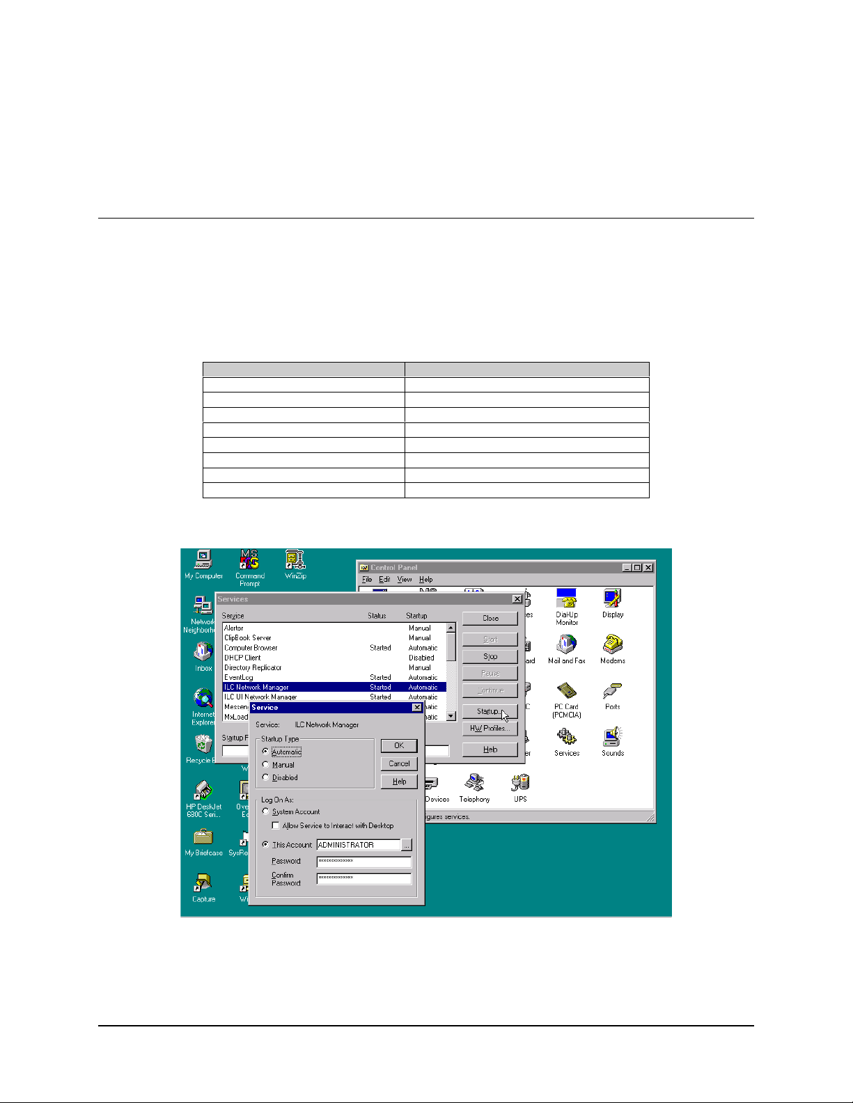
3.4.2.1 Configure ILCNET
Path: Start\Settings\Control Panel\Services
Notes:
1. Make sure the Loopback adapter is installed from Windows NT.
2. Default setting for ILC Network Manager is: MANUAL and NOT RUNNING.
Command Response
Click on ILC NETWORK MANAGER
Click on STARTUP
Enable AUTOMATIC
Enable THIS ACCOUNT
Verify (or Type) ADMINISTRATOR
Verify Password (or Type) ilc (lower case)
Confirm Password ilc (lower case)
Click on OK
3–14 Rev. 0
Page 94

MiniMAC Rack Management System MiniMAC Program
3.4.2.2 Configure ILC UI Netman
Path: Start\Setting\Control Panel\Services
Note:
Default setting for ILC UI Network Manager is MANUAL and NOT RUNNING.
Command Response
Click on ILCUINETWORK MANAGER
Click on STARTUP
Enable AUTOMATIC
Enable THIS ACCOUNT
Verify (or Type) ADMINISTRATOR
Type Password ilc (lower case)
Confirm Password (by typing) ilc (lower case)
Click on OK
Rev. 0 3–15
Page 95

MiniMAC Program MiniMAC Rack Management System
3.5 Create New File Folder for Customer Site
Note:
For the purpose of this manual, EFData is the customer.
Path: My Computer\(C:)
Create a new file as follows:
Command Response
Click on NEW FILE
Name New File EFData
Perform the following:
Command Response
Locate: SITE.REG and OVE RVIEW.MAC Files are located on MiniMAC CD or
backup floppy disk.
Copy: SITE.REG and OVERVIEW.MAC Place files in n ew EFDat a fol der.
Create new folders: Name folders: BITMAP and DATABASE
Place new folders. Put new folders in the site director y
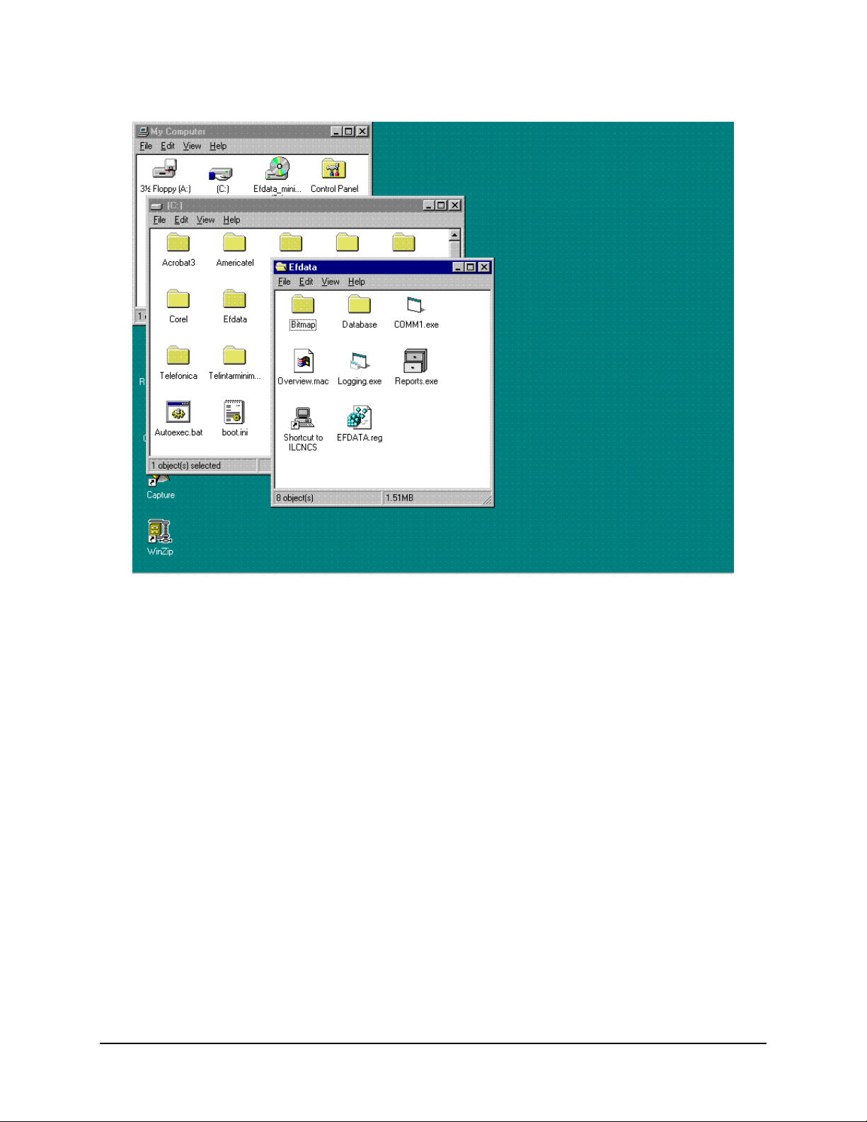
Copy specific files in new site directory:
(Found in C:\Programs Files\ILCNCS)
Create shortcut for ILCNCS Place shortcut in site directory. (Drag with
Copy: COMM1.EXE
REPORTS.EXE
LOGGING.EXE
right mouse button and choose shortcut.)
CAUTION
Ensure to double-click on the SITE.REG file. Program may fail to function.
3–16 Rev. 0
Page 96
MiniMAC Rack Management System MiniMAC Program
Note:
When completed there will be six files and two file folders located in the SITE directory.
Rev. 0 3–17
Page 97

MiniMAC Program MiniMAC Rack Management System
3.6 Verify ActiveConfiguration File Folder
Note:
ActiveConfiguration is treated as one word. Do not add a space, program will not
function.
Perform the following:
Command Response
Go to DOS Prompt
Type REGEDIT
Go to LOCAL MAC HINE/SOFTWARE /ILC
Open ILC File Folder
Verify String ActiveConfiguration “EFData”
Note:
The system name and the active user name shall be identical. (This is located under
REGEDIT.ILC\Adaptive Broadband\Parameters.)
3–18 Rev. 0
Page 98

MiniMAC Rack Management System MiniMAC Program
3.6.1 Create ActiveConfiguration File
ActiveConfiguration
If
Command Response
Go to EDIT
Click on NEW
Click on STRING VALUE
Type ActiveConfiguration
<ENTER>
Double Click NEW STRING
Type Adaptive Broadband
<ENTER>
Restart Computer
string is not present, perform the following:
Rev. 0 3–19
Page 99

MiniMAC Program MiniMAC Rack Management System
3.7 Run MiniMAC Program
Start MiniMAC program as follows:
Click on: ILCNCS shortcut
or
Go to: Start\Programs\ILCNCS
Observe the three program windows at the bottom of the screen.
ILCNCS
•
COMM1
•
Logging
•
Note:
When the program is initiated, it will require 15 minutes (approximately) for the
polling sequence to communicate with all the devices. Faults, alarms, communication
alarms will not be accurate until the polling sequence has completed one cycle.
3–20 Rev. 0
Page 100

MiniMAC Rack Management System MiniMAC Program
3.8 User Login
Log on as a user. From the drop-down menu, perform the following:
Command Response
Select USER
Select LOGON
Select SYSTEM
Type Password
<ENTER>
Create Password for additional users
Default Password is MINIMAC for system user. It is recommended that the
password be changed for user preference and security purposes. Login
CAUTION
passwords are case sensitive. Incorrect password or entry can prevent the
system from operating.
Rev. 0 3–21
 Loading...