

Page 1

SpectraCast
DTMX5000
IP Gateway
Installation and Operation Manual
Part Number MN/DTMX5000.IOM Revision 1
®
Page 2

Page 3

Comtech EFData is an ISO 9001
Registered Company.
®
SpectraCast
DTMX5000
IP Gateway
Installation and Operation Manual
Part Number MN/DTMX5000.IOM
Revision 1
September 11, 2000
Comtech EFData, 2114 West 7th Street, Tempe, Arizona 85281 USA, (480) 333-2200, FAX: (480) 333-2161.
Copyright © Comtech EFData, 2000. All rights reserved. Printed in the USA.
Page 4

Customer Support
Contact the Comtech EFData Customer Support Department for:
• Product support or training
• Information on upgrading or returning a product
• Reporting comments or suggestions concerning manuals
A Customer Support representative may be reached at:
Comtech EFData
Attention: Customer Support Department
2114 West 7th Street
Tempe, Arizona 85281 USA
(480) 333-2200 (Main Comtech EFData Number)
(480) 333-4357 (Customer Support Desk)
(480) 333-2161 FAX
or, E-Mail can be sent to the Customer Support Department at:
service@comtechefdata.com
Contact us via the web at www.comtechefdata.com.
1. To return a Comtech EFData product (in-warranty and out-of-warranty) for
repair or replacement:
2. Request a Return Material Authorization (RMA) number from the Comtech
EFData Customer Support Department.
3. Be prepared to supply the Customer Support representative with the model
number, serial number, and a description of the problem.
4. To ensure that the product is not damaged during shipping, pack the product in
its original shipping carton /p ack ag ing .
5. Ship the product back to Comtech EFData. (Shipping charges should be prepaid.)
For more information regarding the warranty policies, see Warranty Policy, p. xii.
ii Rev. 1
Page 5

Table of Contents
Customer Support.......................................................................................................................................................ii
Overview of Changes to Previous Edition..............................................................................................................viii
About this Manual ...................................................................................................................................................viii
Conventions and References....................................................................................................................................ix
Reporting Comments or Suggestions Concerning this Manual...............................................................................ix
EMC Compliance........................................................................................................................................................ x
EN55022 Compliance............................................................................................................................................... x
Federal Communications Commission (FCC).......................................................................................................... x
European Low Voltage Directive..............................................................................................................................xi
Warranty Policy........................................................................................................................................................xii
Limitations of Warranty..........................................................................................................................................xii
Exclusive Remedies................................................................................................................................................ xii
Disclaimer ..........................................................................................................................................................xii
TABLE OF CONTENTS.................................................................................................III
INTRODUCTION........................................................................................................1–1
1.1 Introduction................................................................................................................................... 1–1
1.2 Description..................................................................................................................................... 1–2
1.2.1 Proxy Servers......................................................................................................................................1–4
1.2.2 Central Configuration Unit..................................................................................................................1–4
1.2.3 Network Management System............................................................................................................1–4
1.3 DTMX5000 Features.....................................................................................................................1–5
1.3.1 IP Multicast......................................................................................................................................... 1–6
1.3.2 IGMP Client........................................................................................................................................ 1–6
1.3.3 Data Mapping and DVB Mapping......................................................................................................1–6
1.3.4 Quality of Service ............................................................................................................................... 1–6
1.3.5 On-the-Fly Configuration.................................................................................................................... 1–7
Rev. 1 iii
Page 6

Preface DTMX5000 IP Gateway
1.3.6 Packet Encryption ............................................................................................................................... 1–7
1.3.7 Dual Input NIC.................................................................................................................................... 1–7
1.3.8 Accounting.......................................................................................................................................... 1–8
1.3.9 Auxiliary Transport Stream Input.......................................................................................................1–8
1.3.10 Downloading Software........................................................................................................................ 1–8
1.4 DTMX5000 Configuration...........................................................................................................1–9
1.4.1 DTMX5000 Application.....................................................................................................................1–9
1.4.2 Local Configuration............................................................................................................................1–9
1.4.3 VGA Display....................................................................................................................................... 1–9
1.4.4 Remote Configuration ......................................................................................................................... 1–9
1.4.5 Firmware.............................................................................................................................................1–9
INSTALLATION.........................................................................................................2–1
2.1 Overview........................................................................................................................................ 2–1
2.2 Connect and Configure................................................................................................................. 2–2
2.3 Starting the DTMX5000............................................................................................................... 2–6
2.3.1 Connecting Network Interface Cards.................................................................................................. 2–7
2.3.2 Connect the Output Transport Stream................................................................................................. 2–7
2.3.3 Telnet Terminal...................................................................................................................................2–8
CONFIGURING THE GATEWAY USING A TERMINAL...........................................3–1
3.1 Overview........................................................................................................................................ 3–1
3.2 Editing the CFG.INI Parameters.................................................................................................3–2
3.2.1 General Parameters ............................................................................................................................. 3–4
3.2.2 Network Parameters............................................................................................................................ 3–8
3.2.3 CCU Parameters................................................................................................................................ 3–13
3.2.4 DVB Mapping Parameters................................................................................................................3–14
3.3 SNMP Parameters.......................................................................................................................3–20
3.3.1 Get Community String......................................................................................................................3–20
3.3.2 Set Community String....................................................................................................................... 3–20
3.4 Writing the CFG.INI Parameters.............................................................................................. 3–21
3.4.1 Write Parameters to CFG.INI and Reset........................................................................................... 3–21
3.4.2 Write Parameters to CFG.INI without Reset.....................................................................................3–22
3.4.3 Discarding Changes to the CFG.INI File.......................................................................................... 3–23
3.5 Configuring Maintenance Parameters...................................................................................... 3–24
3.5.1 Description of the Maintenance Parameters...................................................................................... 3–26
DTMX5000 MIB FILE.................................................................................................4–1
4.1 Overview........................................................................................................................................ 4–1
4.2 Maintenance Information Base.................................................................................................... 4–2
4.2.1 Operation Mode Parameters................................................................................................................ 4–2
iv Rev. 1
Page 7

DTMX5000 IP Gateway Preface
4.2.2 Network Interface Configuration Parameters......................................................................................4–8
4.2.3 DVB Interface Parameters ................................................................................................................ 4–12
4.2.4 Multicast Channel Parameters........................................................................................................... 4–18
4.2.5 Group Parameters.............................................................................................................................. 4–19
4.2.6 Static Users Parameters................................................................................................... .................. 4–22
4.2.7 CCU Parameters................................................................................................................................ 4–25
4.2.8 Software Download Parameters........................................................................................................ 4–28
4.2.9 General Statistics Parameters............................................................................................................ 4–33
4.2.10 Client Data Flow Statistics Table...................................................................................................... 4–36
4.2.11 Client Configuration Parameters Table............................................................................................. 4–41
TROUBLESHOOTING...............................................................................................5–1
5.1 Troubleshooting ............................................................................................................................ 5–1
5.1.1 The Gateway Does Not Power Up......................................................................................................5–2
5.1.2 No Communication Between the Gateway and the Local Terminal................................................... 5–2
5.1.3 The Gateway Does Not Reply to Ping from the Control and Management Interface.........................5–2
5.1.4 The Gateway Does Not Reply to Ping from the Transportation Interface .......................................... 5–2
5.1.5 Gateway Statistics Tables Indicate that there is No Data Flow to Users............................................. 5–2
5.1.6 The Gateway Does Not Reply to Telnet/FTP Users............................................................................5–3
5.1.7 No Telnet/FTP/SNMP Communication from Outside the LAN......................................................... 5–3
5.1.8 The Gateway Does Not Reply to SNMP Set or Get Commands......................................................... 5–3
5.1.9 The Modulator Cannot Synchronize with the Transport Stream (TS) Generated by the Gateway ..... 5–3
5.1.10 The CCU Does Not Communicate with the Gateway......................................................................... 5–4
5.1.11 The Gateway's Output is Connected to a DVB Multiplexer's Input but the DVB Multiplexer Indicates
that there is NO TS Input...................................................................................................... .......... 5–4
5.1.12 MPE Compatible Receivers Cannot Receive IP Data from the Gateway ........................................... 5–4
5.2 Ongoing Maintenance...................................................................................................................5–5
5.2.1 A User Indicates RF Lock but Cannot Receive Data.......................................................................... 5–5
5.2.2 The Gateway Statistics indicate a Large Number of Discarded Packets............................................. 5–5
5.2.3 The Gateway Does Not Reply to Telnet but Does Reply to SNMP and Terminal Communication... 5–6
5.2.4 A User Cannot Receive Multicast Channels or Loses Multicast Packets............................................5–6
5.2.5 A PC Connected to a LAN Fed by a Satellite Receiver (Static User) Does Not Receive Unicast
Transmissions ................................................................................................................................. 5–6
5.2.6 The CCU Cannot Register a User in the Gateway..............................................................................5–6
SPECIFICATIONS .................................................................................................... A–1
A.1 Overview....................................................................................................................................... A–1
A.2 Specifications................................................................................................................................ A–1
A.3 External Connections................................................................................................................... A–4
A.4 Parallel Output Pin Assignment................................................................................................. A–5
CENTRAL CONFIGURATION UNIT..........................................................................B-1
B.1 Overview........................................................................................................................................B-1
B.2 DTMX5000 Service.......................................................................................................................B-2
Rev. 1 v
Page 8

Preface DTMX5000 IP Gateway
B.3 Starting a Session..........................................................................................................................B-3
B.3.1 DTMX5000 Client Application Contacts CCU .................................................................................. B-3
B.3.2 CCU Contacts Authentication Server..................................................................................................B-3
B.3.3 Authentication Server Allows Access................................................................................................. B-4
B.3.4 CCU Contacts DTMX5000 Gateway.................................................................................................. B-4
B.3.5 CCU Contacts Billing Server..............................................................................................................B-4
B.3.6 CCU Contacts Proxy Server................................................................................................................ B-5
B.3.7 CCU Responds to DTMX5000 Application........................................................................................ B-5
B.4 Processing Information Requests ................................................................................................ B-6
B.4.1 Proxy Server Requests/Receives Information..................................................................................... B-6
B.4.2 Proxy Server Sends Information to DTMX5000 Gateway..................................................................B-6
B.4.3 DTMX5000 Gateway Routes Information to Subscriber.................................................................... B-6
B.5 Terminating a Session................................................................................................................... B-7
B.6 Installing the CCU ........................................................................................................................B-7
B.6.1 System Requirements.......................................................................................................................... B-7
B.6.2 Installing Data Access Objects (DAO)................................................................................................B-8
B.6.3 Installing the CCU Application........................................................................................................... B-9
B.6.4 Getting Started .................................................................................................................................. B-10
B.6.5 Uninstalling the CCU Application....................................................................................................B-11
B.7 Configuring the CCU.................................................................................................................. B-12
B.7.1 Specifying CCU Server Properties.................................................................................................... B-12
B.7.2 Adding a CCU Server ....................................................................................................................... B-15
B.7.3 Deleting a CCU Server...................................................................................................................... B-15
B.8 Configuring the CCU to the RADIUS Authentication Server ................................................B-16
B.9 Configuring the CCU to the RADIUS Billi ng Server .............................................................. B-19
B.10 Configuring the CCU to the Proxy Server................................................................................ B-22
B.11 Configuring the CCU to the DTMX5000Gateway................................................................... B-24
B.12 Operating the CCU..................................................................................................................... B-26
B.12.1 Monitoring the Events Log ............................................................................................................... B-26
B.12.2 The CCU Logfile Mechanism........................................................................................................... B-27
B.13 Client Parameters Sent from the RADIUS............................................................................... B-30
B.13.1 Authentication Server........................................................................................................................ B-30
HIGH AVAILABILITY SERVER (HAS-2000)............................................................C–1
C.1 Overview....................................................................................................................................... C–1
C.1.1 Standard References............................................................................................................................C–2
C.2 General Description......................................................................................................... ............ C–2
C.2.1 Brief System Description....................................................................................................................C–2
C.3 Detailed Description..................................................................................................................... C–3
C.3.1 System Details.....................................................................................................................................C–3
vi Rev. 1
Page 9

DTMX5000 IP Gateway Preface
C.3.2 System Diagram..................................................................................................................................C–5
C.3.3 Technical Specifications .....................................................................................................................C–6
Figures
Figure 1-1. The DTMX5000................................................................................................................................ 1–1
Figure 1-2. DTMX5000 Environment................................................................................................................. 1–3
Figure A-1. Forwarding Rate as a Function of Packet Size................................................................................ A–3
Figure A-2. External Connections...................................................................................................................... A–4
Figure C-1. System Diagram...............................................................................................................................C–5
Tables
Table A-1. Gateway Specification...................................................................................................................... A–2
Table A-2. Parallel Output Pin Assignment........................................................................................................A–5
Rev. 1 vii
Page 10

Preface DTMX5000 IP Gateway
Overview of Changes to Previous Edition
This revision supersedes part number MN/DTMX5000 Rev. 0 dated June 9, 2000.
A summary of the changes made for Rev. 1 includes:
General Updated company name and revision level/date
Chapter 1 Updated photograph and graphics
Chapter 3 Updated General parameters
Updated 3.2 Editing CFG.INI parameters
Updated 3.2.1 General Parameters
Added 3.2.1.9 Gateway Description section
Updated 3.2.2 Network parameters
Updated 3.2.2.5 Transportation
Deleted 3.2.10 Multicast Key Period
Updated 3.2.3 CCU Parameters
Updated 3.2.4 DVB Mapping Parameters
Updated 3.3 SNMP Parameters
Updated 3.5 Maintenance Parameters
Updated 3.5.1 Description of Maintenance Parameters
About this Manual
This manual provides installation and oper at ion info rmation for the Comtech EFData
DTMX5000 IP Gateway. This is a technical document intended for earth station
engineers, technicians, and operators responsible for the operation and maintenance of
the DTMX5000 IP Gateway.
viii Rev. 1
Page 11

DTMX5000 IP Gateway Preface
Conventions and References
Cautions and Warnings
CAUTION indicates a hazardous situation that, if not avoided, may result in
minor or moderate injury. CAUTION may also be used to indicate other
CAUTION
unsafe practices or risks of property damage.
WARNING indicates a potentially hazardous situation that, if not avoided,
could result in death or serious injury.
WARNING
Metric Conversion
Metric conversion information is located on the inside back cover of this manual. This
information is provided to assist the operator in cross-referencing English to Metric
conversions.
Recommended Standard Designations
Recommended Standard (RS) Designations have been superseded by the new designation
of the Electronic Industries Association (EIA). References to the old designations are
shown only when depicting actual text displayed on the screen of the unit (RS-232, RS485, etc.). All other references in the manual will be shown with the EIA designations
(EIA-232, EIA-485, etc.) only.
Trademarks
Other product names mentioned in this manual may be trademarks or registered
trademarks of their respective companies and are hereby acknowledged.
Reporting Comments or Suggestions Concerning this Manual
Comments and suggestions regarding the content and design of this manual will be
appreciated. To submit comments, please contact the Comtech EFData Customer Support
Department.
Rev. 1 ix
Page 12

Preface DTMX5000 IP Gateway
EMC Compliance
EN55022 Compliance
This equipment meets EN55022.
This is a Class A product. In a domestic environment, it may cause radio interference in
which the user may be required to take adequate measures.
Federal Communications Commission (FCC)
Note:
All cables shall be shielded.
This equipment has been tested and found to comply with the limits for a Class A digital
device, pursuant to Part 15 of the FCC rules. These limits are designed to provided
reasonable protection against harmful interference when the equipment is operated in a
commercial environment.
This equipment generates, uses, and can radiate radio frequency energy and, if not
installed and used in accordance with the instruction manual, may cause harmful
interference to radio communications. Operation of this equipment in a residential area is
likely to cause harmful interference in which case the user will be required to correct the
interference at his own expense.
x Rev. 1
Page 13
DTMX5000 IP Gateway Preface
European Low Voltage Directive
The following information is applicable for the European Low Voltage Directive
(EN60950):
<HAR> Type of power cord required for use in the European Community.
CAUTION: Double-pole/Neutral Fusing
!
International Symbols:
ACHTUNG: Zweipolige bzw. Neutralleiter-Sicherung
Alternating Current.
Fuse.
Safety Ground.
Chassis Ground.
Note:
For additional symbols, refer to “Cautions and Warnings” listed earlier in this
preface.
Rev. 1 xi
Page 14

Preface DTMX5000 IP Gateway
Warranty Policy
This Comtech EFData product is warranted against defects in material and workmanship
for a period of one year from the date of shipment. During the warranty period, Comtech
EFData will, at its option, repair or replace products that prove to be defective.
For equipment under warranty, the customer is responsible for freight to Comtech
EFData and all related custom, taxes, tariffs, insurance, etc. Comtech EFData is
responsible for the freight charges
the customer. Comtech EFData will return the equipment by the same method (i.e., Air,
Express, Surface) as the equipment was sent to Comtech EFData.
only
for return of the equipment from the factory to
Limitations of Warranty
The foregoing warranty shall not apply to defects resulting from improper installation or
maintenance, abuse, unauthorized modification, or operation outside of environmental
specifications for the product, or, for damages that occur due to improper repack ag ing of
equipment for return to Comtech EFData.
No other warranty is expressed or implied. Comtech EFData specifically disclaims the
implied warranties of merchantability and fitness for particular purpose.
Exclusive Remedies
The remedies provided herein are the buyer's sole and exclusive remedies. Comtech
EFData shall not be liable for any direct, indirect, special, incidental, or consequential
damages, whether based on contract, tort, or any other legal theory.
Disclaimer
Comtech EFData has reviewed this manual thoroughly in order that it will be an easy-touse guide to your equipment. All statements, technical information, and
recommendations in this manual and in any guides or related documents are believed
reliable, but the accuracy and completeness thereof are not guaranteed or warranted, and
they are not intended to be, nor should they be understood to be, representations or
warranties concerning the products described. Further, Comtech EFData reserves the
right to make changes in the specifications of the products described in this manual at any
time without notice and without obligation to notify any person of such changes.
If you have any questions regarding your equipment or the information in this manual,
please contact the Comtech EFData Customer Support Department.
xii Rev. 1
Page 15
This chapter provides a general description of the DTMX5000 IP Gateway, herein after
referred to as, “the DTMX5000” or “Gateway.”
1.1 Introduction
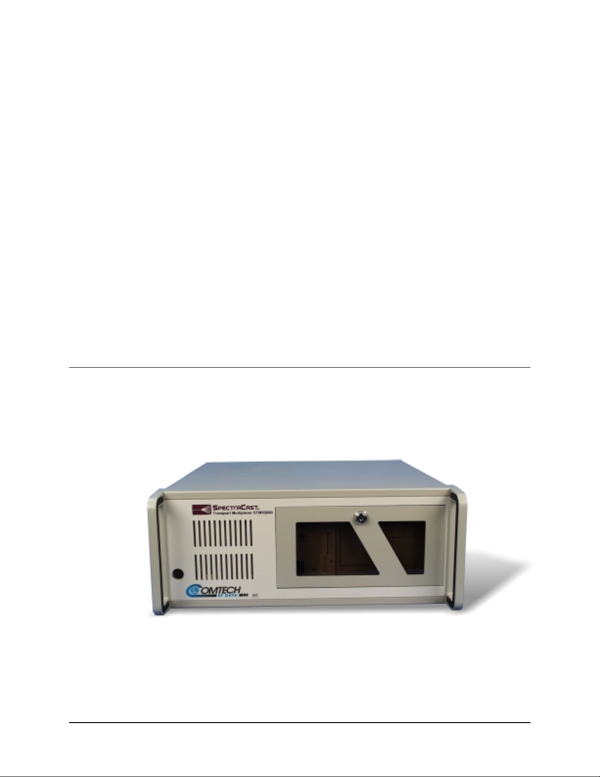
The DTMX5000 IP Gateway (Figure 1-1) provides a high-speed connection between a
network and a satellite or cable DVB channel. The DTMX5000 is compliant with DVB
MPE standard EN 301.192. (See Appendix A.)
Chapter 1.
INTRODUCTION
1
Figure 1-1. The DTMX5000
Rev. 1 1–1
Page 16

Introduction DTMX5000 IP Gateway
1.2 Description
On the input-side, the DTMX5000 connects to two 10/100 BaseT Local Area Networks
(LANs). To ensure security and support high availability, the DTMX5000 has two
separate 10/100 BaseT Network Interface Cards (NICs).
Transportation NIC
Data from this NIC can only be forwarded to the
DVB channel. This NIC can be connected to an
unsecured network (such as the Internet).
Control and Management NIC
Connected to a secured network.
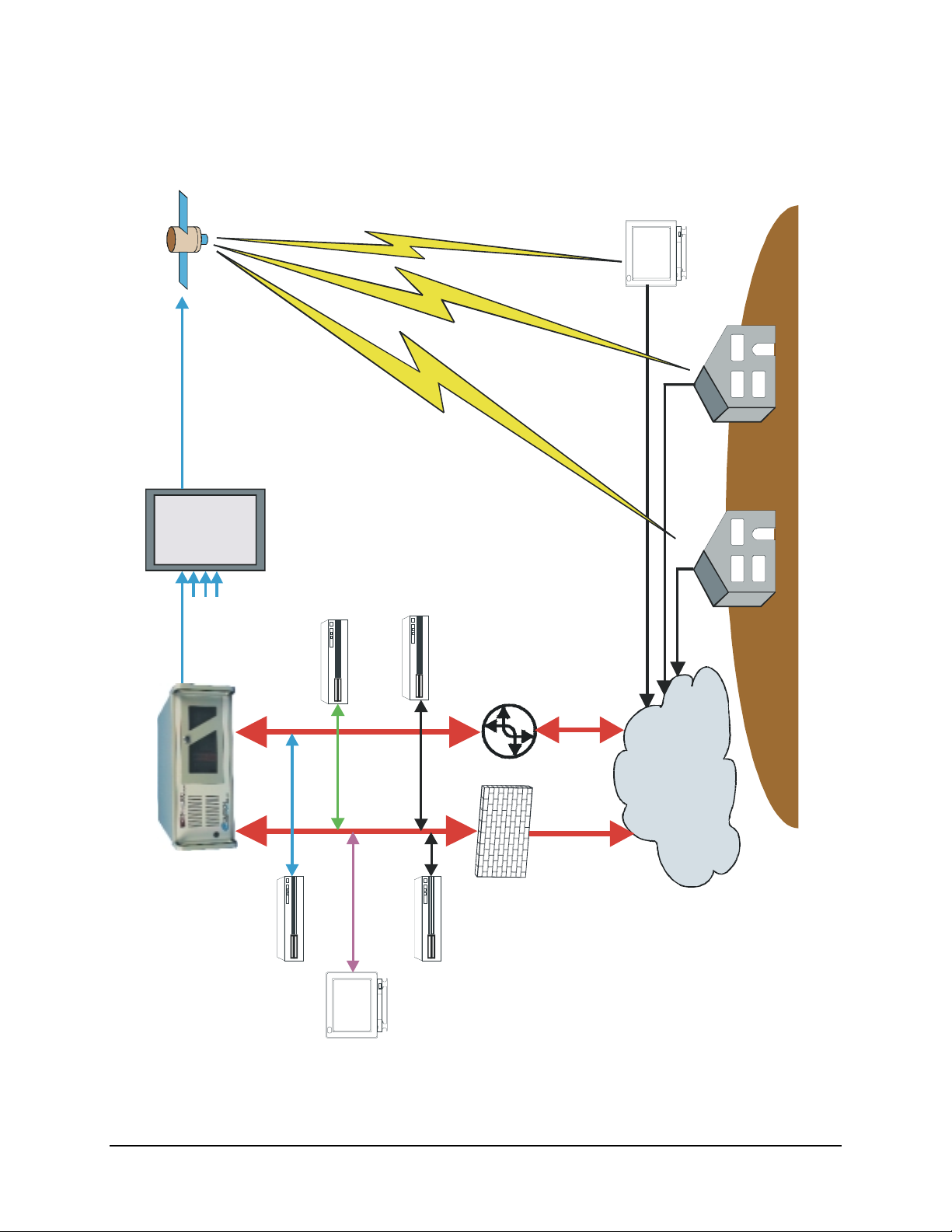
The DTMX5000 links to a DVB modulator for the Single Channel per Carrier (SCPC)
transmissions, or to a DVB Multiplexer (Mux), connected to a QPSK modulator in the
case of Multiple Channels per Carrier (MCPC) transmissions. The DTMX5000
environment is shown in Figure 1-2.
1–2 Rev. 1
Page 17
DTMX5000 IP Gateway Introduction
DVB Channel
CATC/Satellite
SUBSCRIBER
SUBSCRIBERS
DVB MUX
(Optional)
RADIUS
Billing
RADIUS
Authentication
Video
Audio
Stream
Informatio n
Server
Server
PSTN Modem to localISP
Router
LAN
Transportation
Gateway
C&M LAN
Line
Auxiliary Transport
Stream Input
Proxy Server
Central
Configuration
NMS
Firewall
INTERNET
Figure 1-2. DTMX5000 Environment
Rev. 1 1–3
Page 18

Introduction DTMX5000 IP Gateway
1.2.1 Proxy Servers
At data request, the requested packet is routed to the proxy server. The proxy server acts
as an intermediary between the final destination and the subscriber. The proxy server
retrieves the data from its cache or the Internet, and returns the requested data to the
subscriber via the DTMX5000.
1.2.2 Central Configuration Unit
The Central Configuration Unit (CCU) can control the DTMX5000. The CCU is an
application running on a Windows NT station at the hub. This application monitors
subscriber’s activities, selects the proxy server for each session, maintains the routing
table on the proxy table server, and interacts with external billing and authentication
systems. (See Appendix B.)
As the subscriber logs On, the CCU notifies the DTMX5000 of the subscriber’s:
• Quality of Server (QoS)
• Group Identification (ID)
• Encryption Parameters
When the subscriber logs Off, the CCU updates the DTMX5000 and collects the
accounting information accumulated by the DTMX5000 for the subscriber. The CCU
connects to the Control and Management (C&M) LAN.
• If the C&M LAN is protected by a Firewall, the appropriate actions must be
taken to ensure connection between the CCU and the server (RIP2 messages
from the CCU should be able to reach the proxy server) and between the CCU
and the clients.
• For additional information, refer to the CCU User’s Manual.
1.2.3 Network Management System
The DTMX5000 is an SNMP V2 client and can be fully controlled by any ANMP-based
NMS application. The MIB parameters include the unit’s configuration, statistic and
diagnostic information. By editing and viewing these parameters, the service provider can
configure and control the DTMX5000.
The NMS also enables the service provider to view and monitor realtime performance
statistics, for example: Client information, memory usage, and packet information. The
statistics can then be evaluated to enhance the QoS offered to subscribers.
1–4 Rev. 1
Page 19

DTMX5000 IP Gateway Introduction
1.3 DTMX5000 Features
The units’s many configuration options enable service providers to tailor the operation of
the DTMX5000 to suit their specific circumstances, to improve operational performance
and to offer subscribers a high quality, versatile level of service.
DTMX5000 feature include the following:
• IP Multicast, enabling the same message to be sent to many subscribers
simultaneously.
• IGMP client, enabling easy interfacing with standard routers.
• Data mapping mode for IP datagrams, piping, streaming or multiprotocol
encapsulation (SI-DAT 360).
• Compliance with the DVB MPE standard, according to EN 301.192.
• DVB mapping options, enabling the unit to operate as a fully DVB compatible
system, usable with SCPC and MCPC applications.
• Datagram flushing to maintain TCP/IP performance through DVB multiplexers
with internal buffers.
• QoS prioritizing, to enable the service provider to optimize output bandwidth
allocation according to subscribers profiles while guaranteeing minimum bit-rate
requirements.
• Packet encryption for the privacy of DTMX5000 subscribers.
• Support for up to 8192 PID in the output Transport Stream.
• Dual input NICs, one for transportation and the other for control and
management that ensures security and supports high availability.
• Passwords to enable remote NMS access.
• Remote downloads of new versions of the unit’s software and firmware.
• Auxiliary transport Stream (TS) input to combine with the TS generated by the
DTMX5000.
• On-the-Fly configuration, most DTMX5000 parameters can be configured
without stopping the service.
• Support for both static and dynamic users, using the CCU.
• Support for user groups.
The values for these and other options can be set from the local terminal connected to the
DTMX5000 and, with some restrictions, also from a remote NMS.
Rev. 1 1–5
Page 20

Introduction DTMX5000 IP Gateway
1.3.1 IP Multicast
The DTMX5000 receives TCP/IP datagram addressed to subscribers and maps them onto
a DVB compatible MPEG2 transport stream. The DTMX5000 is capable of mapping two
types of datagrams.
Unicast Packets
Multicasts Packets
Each unicast packet is addresses to one individual user.
Multicast packet are add r essed are addressed to a group of users, and are
simultaneously sent to all members of the group. These packets are usually for
the distribution of files, or for streaming audio or video. It is possible to disable
Multicast broadcasting if, example: this type of transmission is being handled by
a separate DTMX5000. It is also possible to enable multicasting for predefined
channels only.
1.3.2 IGMP Client
The DTMX5000 acts as an IGMP client (RFP 1122). For each registered multicast
channel that it forwards, the unit generates an IGMP request and replies to IGMP queries.
The IGMP protocol is managed on the Transportation NIC only.
1.3.3 Data Mapping and DVB Mapping
Data mapping specifies how IP datagrams are mapped onto the output transport stream.
There are three mapping modes.
• Piping
• Streaming
• Multiprotocol Encapsulation
Data piping and data streaming are proprietary mapping, data piping without encryption
and data streaming with encryption. Multiprotocol encapsulation is used for compatibility
with other DVB based systems.
1.3.4 Quality of Service
Quality of Service (QoS) Management is a feature that determines the amount of
bandwidth each subscriber is allocated. Th is feature can eithe r be enabled or disa ble d.
• When QoS is enabled, subscribers receive their bandwidth share according to the
level of service specified in their individual subscription fees.
• When QoS is disabled, the DTMX5000 will provide best effort service, resulting
in the available bandwidth being equally divided among the various subscribers.
1–6 Rev. 1
Page 21

DTMX5000 IP Gateway Introduction
The DTMX5000 contains two QoS parameters for each user:
• Committed Information Rate
• Maximum Rate
The committed information rate is the maximum the DTMX5000 will allocate to that
individual subscriber. The maximum rate specifics how the overall rate divides among all
subscribers. If at a certain time free bandwidth is available; the subscribers may or may
not receive more than their maximum rate, depending on the specified QoS mode.
1.3.5 On-the-Fly Configuration
Most of the configuration and maintenance parameters of the DTMX5000 can be
configured without disturbing the flow of data. For example: using the NMS, the user can
set a new CIR for a subscriber, without stopping the flow of data to the subscriber.
1.3.6 Packet Encryption
To provide privacy, the data addressed to individual subscribers is encrypted with the
DES algorithm, implementing the CBC mode.
For additional encryption inform ation , refer to F IPS-4 6-2 and FIPS-81 .
1.3.7 Dual Input NIC
To ensure security and support high availability, the DTMX5000 has two input 10/100
BaseT NICs:
Transportation NIC
Control and Manageme nt
Note:
The DTMX5000 supports full functionality even with only one input NIC. In this
case, the C&M input NIC acts as C&M and Transportation.
This NIC does not enable access to the C&M of the
DTMX5000. This NIC can be co nnected to the unsecured
network, such as the Internet. The DTMX5000 design prevents
hackers from gaining acces s to the unit from the transp ortation
NIC.
The Control and Management NIC of the DTMX5000 is via
the Telnet, SNMP, and FTP. This NIC is connected to a
secured C&M network. The C&M NIC can also act as an
additional transportation NIC, enabling the sending of the IP
datagrams from the C&M network to the DVB channel.
Along with security, the two input NICs enable the support the high availability
topologies. High availability will be supported in the next DTMX5000 version.
Rev. 1 1–7
Page 22

Introduction DTMX5000 IP Gateway
1.3.8 Accounting
The CCU informs the DTMX5000 each time a subscriber logs On or Off the system. The
unit creates an account of the packets that each indiv idua l subsc rib ers dow nlo ads, and the
Billing Server later transfers this information for use.
The DTMX5000 also enables full access to the accounting information via the NMS.
This enables an external system to retrieve the information.
1.3.9 Auxiliary Transport Stream Input
If enabled, the Auxiliary Transport Stream (Aux TS) input is compiled with the internal
TS generated by the DTMX5000. The Aux IS input has precedence over the TS
generated by the DTMX5000.
The TS generated by the DTMX5000 can be compiled with the Aux TS input in two
ways:
1. The TS packets generated by the DTMX5000 will be transmitted only when there
is free bandwidth in the output TS of the unit. It is up to the system architecture
to ensure that such free bandwidth is available.
2. The TS packets generated by the DTMX5000 will be transmitted on free
bandwidth, instead of DVB null packets in the Aux TS input.
1.3.10 Downloading Software
To enable new software versions of the DTMX5000 application and firmware to be
downloaded, the NMS system can initiate a TFTP download process from any TFTP
server. The DTMX5000 also supports FTP services.
1.3.10.1 Default Application Fallback
TFTP or FTP may be used to remotely download new software/firmware versions to the
DTMX5000.
In the event that an invalid file is downloaded, the DTMX5000 will lock-up trying to run
the invalid code. To correct this problem, a fixed default software application is provided
on the DTMX5000’s local hard drive. This default application enables the user to
perform the download again.
Note:
The Default application is set by the manufacturer and can not be altered.
Attaching a VGA display, rebooting the DTMX5000, and pressing <D> when prompted
can access this file.
1–8 Rev. 1
Page 23

DTMX5000 IP Gateway Introduction
1.4 DTMX5000 Configuration
The DTMX5000 must be connected to a local serial terminal in order to enable definition
of the unit’s essential configuration parameters.
The DTMX5000 also can be accessed and configured remotely using the unit’s NMS. In
addition, the unit supports remote configuration via a Telnet terminal.
1.4.1 DTMX5000 Application
The operation of the DTMX5000 is determined by a software application, which is
loaded automatically on Startup. A new release of this application can be downloaded to
the DTMX5000 from a remote station. A new software release also can be downloaded
using FTP.
1.4.2 Local Configuration
The unit’s default operational behavior is determined by a configuration file (
which resides on the unit’s internal hard drive. This file is persistent and is loaded by
default into memory when the DTMX5000 is started up.
CFG.INI
The
in the form of a <DUMB> terminal or PC.
file can be accessed and edited directly from a locally connected terminal,
1.4.3 VGA Display
An optional VGA display can be connected to the DTMX5000, for viewing startup and
operational messages.
1.4.4 Remote Configuration
The DTMX5000 also can be controlled and configured remotely from a Telnet terminal.
Setting the relevant parameters via the local terminal can enable Telnet services.
1.4.5 Firmware
The DTMX5000 contains a Field Programmable Gate Array (FPGA) which performs
most of the mapping of IP datagrams onto the MPEG2 transport stream. The
configuration of this FPGA is downloaded by the DTMX5000 application each time the
DTMX5000 restarts.
CFG.INI
),
Rev. 1 1–9
Page 24

Introduction DTMX5000 IP Gateway
This page is intentionally left blank.
1–10 Rev. 1
Page 25

This section provides important information concerning the installation of the
DTMX5000.
2.1 Overview
Note:
For security reasons, the unit’s vital parameters can only be configured through a
direct serial connection to a local terminal. The remaining parameters can be configured
either via the local terminal or remotely via a Telnet terminal.
An optional VGA display also can be connected to the DTMX5000 using a 15-pin cable
for viewing, boot, and operational messages.
Chapter 2.
INSTALLATION
2
Never install the unit where it may be exposed to rain or moisture. Water in
the unit may damage components and create a shock hazard.
CAUTION
Never remove the cover. This multiplexer has very sophisticated circuitry
that should only be serviced by a fully trained technician.
Removal of the cover might:
Void the warranty
••••
Allow ESD damage to components
••••
Create a shock hazard
••••
Rev. 1 2–1
Page 26

Installation DTMX5000 IP Gateway
2.2 Connect and Configure
Perform the following procedures to connect the local terminal to the DTMX5000 and
establish a communications link.
Note:
Either a PC or a <DUMB> terminal, (a terminal processing no programming
capabilities) can be used as a monitor. A PC may run a terminal emulation application,
such as HyperTerminal, which is supplied as an accessory with Win95. The PC must
have the following minimum requirements:
• Windows OS, with 16 Mbit/s of RAM
• EIA-232 Serial cable
• HyperTerminal application
To connect the local terminal to the DTMX5000, proceed as follows:
1. Attach one end of a EIA-232 serial cable to the back of the DTMX5000’s COM1
connector.
2. Connect the other end of the EIA-232 serial cable to the COM1 or COM2
connector of the PC.
Configure the local term inal as foll ow s:
Note:
To enable a communication link between the terminal and the DTMX5000, it is
necessary to configure the local te rm inal. Th is conf ig urat ion can be perfo rmed with the
standard Windows HyperTerminal application.
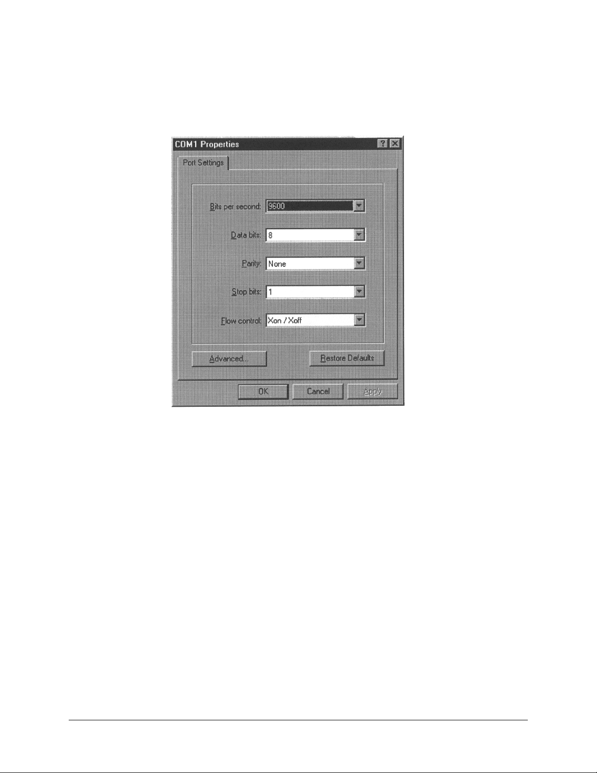
The local terminal must be configured to the following parameters:
• Baud rate: 9600 bit/s
• Data bits: 8
• Parity: None
• Stop bit: 1
• Flow Control: Xon/Xoff
2–2 Rev. 1
Page 27
DTMX5000 IP Gateway Installation
To configure the local termina l to the required p aram eters, proceed to the Start Menu bar
and as follows:
1. Select the Program option to display the Programs menu.
2. Select the Accessories option to display the Accessories menu.
3. Select the HyperTerminal program group. The HyperTerminal program group
window opens.
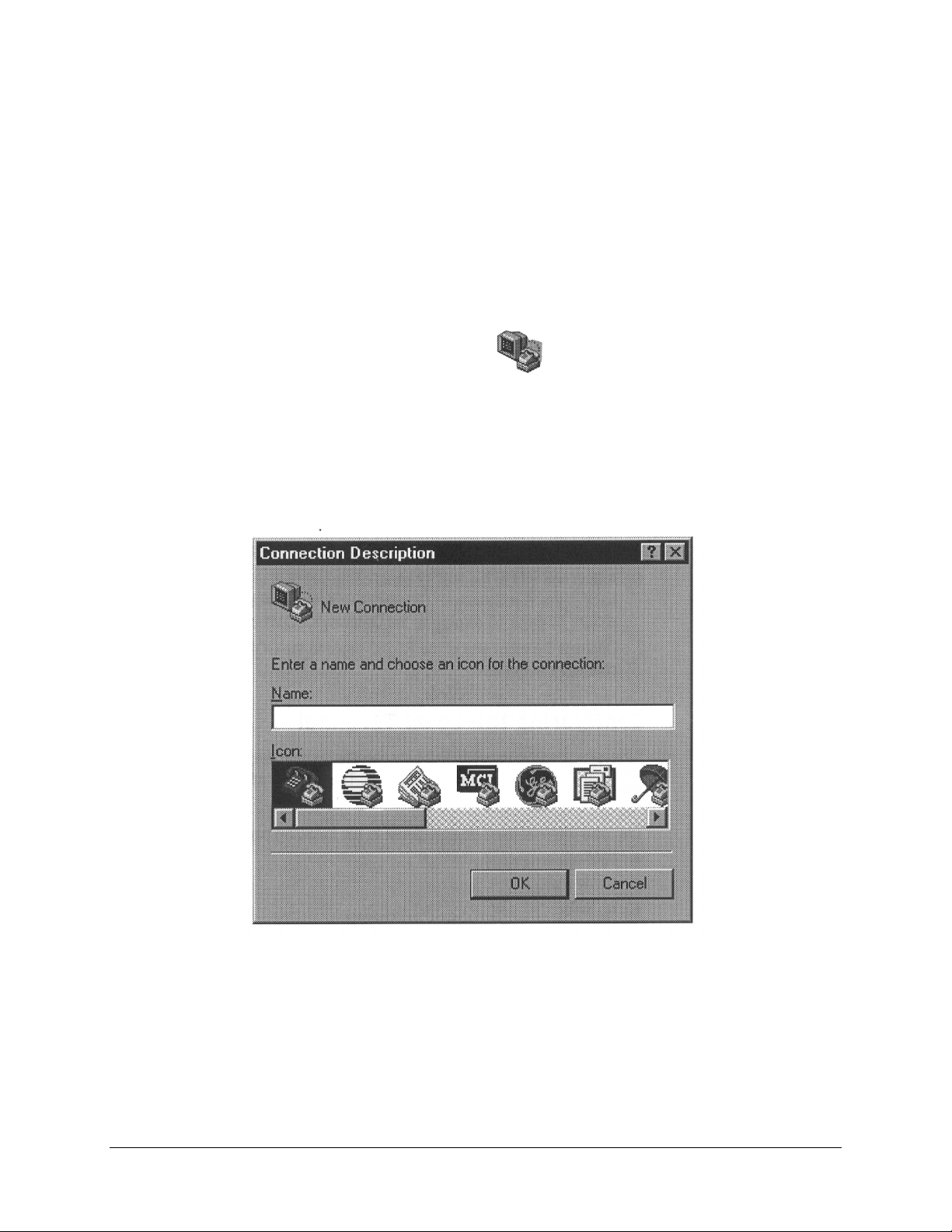
4. Double-click the Hypertrm.exe
. The Connection Description Windows
opens.
5. Enter a name and choose an icon for the connection.
Rev. 1 2–3
Page 28
Installation DTMX5000 IP Gateway
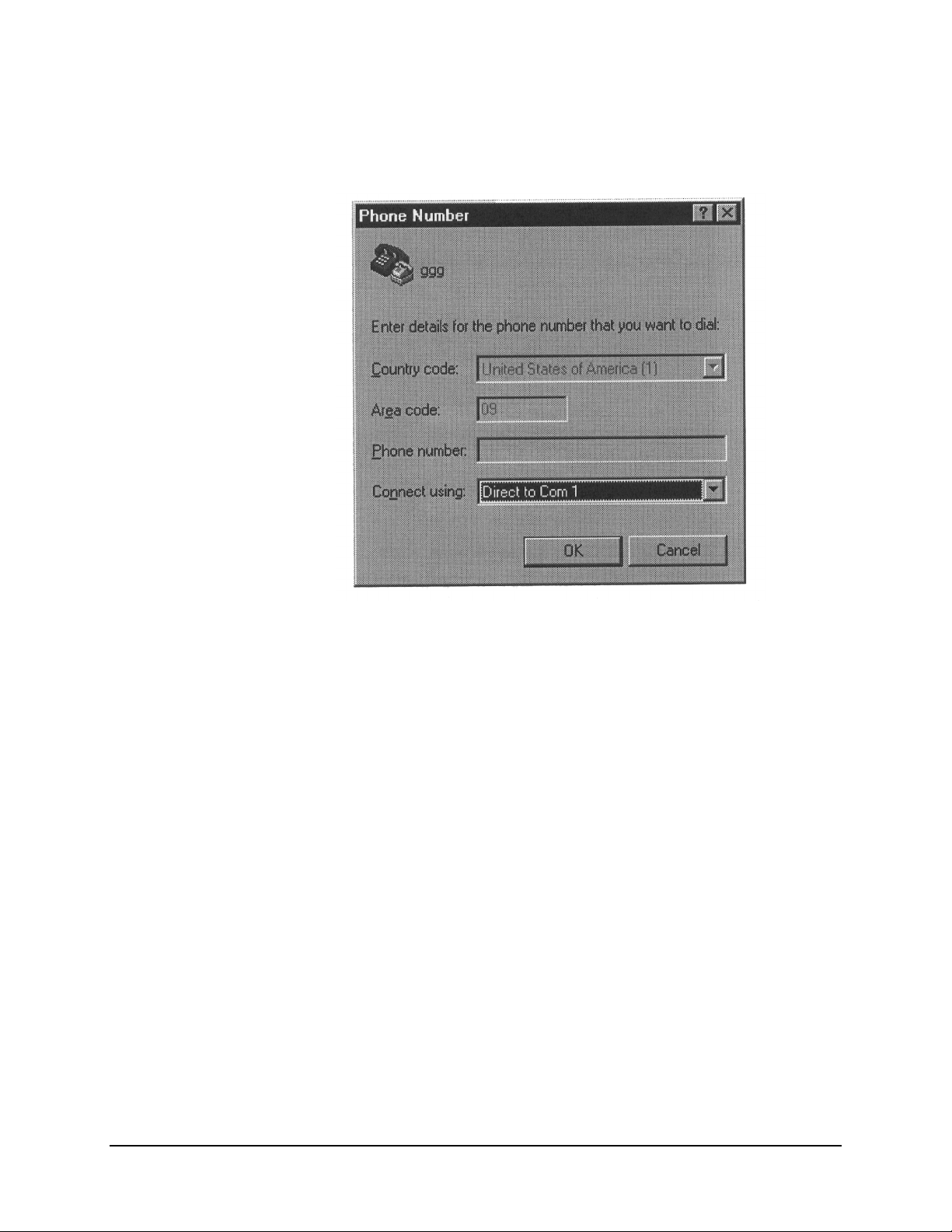
6. Click OK. The window closes and the Phone Number window opens.
7. In the Connect using field, scroll down the dropdown list and select either
COM 1 or COM 2, depending where the local terminal is connected. Click OK.
The Phone Number window closes and the COM Properties window opens.
2–4 Rev. 1
Page 29
DTMX5000 IP Gateway Installation
8. In the Port Setting tab, enter the setting exactly as shown.
9. Click OK. The COM Properties window closes and is replaced with the
HyperTerminal window.
Rev. 1 2–5
Page 30
Installation DTMX5000 IP Gateway
2.3 Starting the DTMX5000
Note:
The DTMX5000 can be started once the local terminal has been connected and
configured. The optional VGA display can be connected at this time.
To start up the DTMX5000 and local terminal, proceed as follows:
Note:
Ensure the local terminal is connected and configured.
1. Double-click the icon defined for the local te rminal’s DTMX5000 connection.
The HyperTerminal window opens.
2. Power-up the DTMX5000 and the local terminal. Observe the following:
DTMX5000
VGA Display (Optional)
The booter, which is a software program, loads the application program,
and the DTMX5000’s parameters file (CFG.INI), from disk to memory.
The application program controls all the DTMX5000’s functionality.
Then an FPGA programmable ch i p is loaded. This chip is responsible for
the low level bit manipulation which creates the output transport stream.
A confirmation message is displayed, stating that the booter has loaded
the application program.
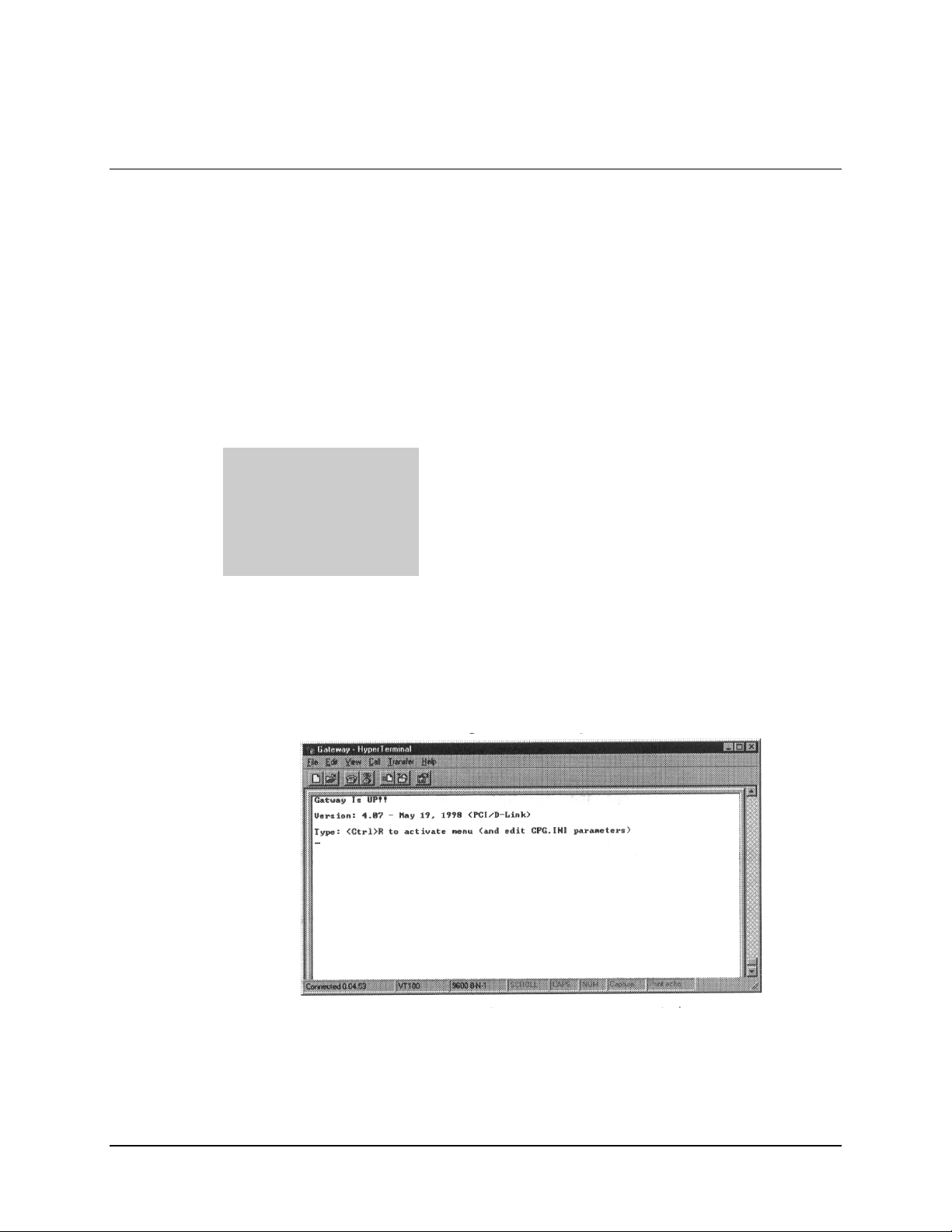
3. Observe the following screen, when the connection between the DTMX5000 and
the local terminal is established. The local terminal and the DTMX5000 are now
connected
4. Press <Ctrl>R to refresh the terminal display.
2–6 Rev. 1
Page 31

DTMX5000 IP Gateway Installation
2.3.1 Connecting Network Interface Cards
Connect the Transportation Input NIC and Control and Management Input NIC.
2.3.1.1 Connect the Transportation NIC
The Transportation Input NIC connects to the Transportation LAN. The NIC is marked
“TX NIC” to avoid confusion with the Control and Management Input NIC. After
installation, verify the connection. The Transportation Input NIC does not reply to Ping
(to ensure security), however, it will reply to ARP.
To verify connection, proceed as follows:
1. Ping from a computer on the Transportation LAN to the IP address of the
Transportation Input NIC.
2. Browse the ARP table of that computer to verify that the IP address of the
Transportation Input NIC appears.
2.3.1.2 Connect the Control and Management Input NIC
The Control and Management NIC connects to the Control and Management LAN. The
NIC is marked “C&M NIC” to avoid confusion with the Control and Management Input
NIC. Set the Control and Management NIC IP address and ping to verify the connection.
2.3.2 Connect the Output Transport Stream
The DTMX5000 has two optional output transport Stream Interfaces, LVDS and ASI.
The Transport Stream is output on both interfaces. According to the target of the
Transport Stream, select the appropriate output.
To verify the connection, proceed as follows.
1. Enable the Flushing mode in the DTMX5000.
2. In Flushing mode, the DTMX5000 generates a non-Null DVB compliant
Transport Stream in its input.
Rev. 1 2–7
Page 32

Installation DTMX5000 IP Gateway
2.3.3 Telnet Terminal
2.3.3.1 Connect the Telnet Terminal
The DTMX5000 as parameters can be configured and edited through a remote telnet
terminal, connected via the Control and Management LAN connection of the
DTMX5000. The Telnet terminal can run on any machine that has a TCP/IP connection
with the DTMX5000. This connection can be local or remote, via the Internet.
Note:
For security reasons, the unit’s vital parameters can only be configured and edited
through a local connection.
To connect the Telnet terminal to the DTMX5000 and establish a communications link
between them, proceed as follows:
Notes:
1. The Telnet terminal is any Telnet terminal application running on a machine that
has a TCP/IP connection with the DTMX5000. All Windows operating
systems contain a Telnet application.
2. Verify the TCP/IP connection between the machine running the Telnet terminal
and the unit, use Ping to the unit.
2–8 Rev. 1
Page 33

DTMX5000 IP Gateway Installation
2.3.3.2 Starting the Telnet Connection
Note:
Windows 95/98 or NT is required for the starting operation.
To start the Telnet connection, proceed as follows :
1. From the Windows Start menu, select the Run option.
2. In the command line, type Telnet. Press <Enter> . The Telnet application opens.
3. Select the Preferences option from the Terminal menu. The Terminal Preferences
dialog box opens:
4. Select the VT100 Arrows check box.
Rev. 1 2–9
Page 34

Installation DTMX5000 IP Gateway
5. Click on the Fonts button. The Font dialog box opens.
6. Select Terminal in the Font list. Click OK.
7. Click OK in the Terminal Preferences dialog box.
8. From the Connect menu, select the Remote System option. The Connect dialog
box appears.
9. Enter the DTMX5000’s IP address in the Host Name field.
2–10 Rev. 1
Page 35

DTMX5000 IP Gateway Installation
10. Click Connect. The Telnet connection to the DTMX5000 is initialized and the
following window is displayed.
11. Enter user Name and Password. (The user name and password are defined using
a local terminal.) The following window should appear if user is authorized.
12. Type Terminal. DTMX5000 is operational.
Rev. 1 2–11
Page 36

Installation DTMX5000 IP Gateway
This page is intentionally left blank.
2–12 Rev. 1
Page 37

CONFIGURING THE GATEWAY
DTMX5000 parameters can be configured through a menu driven interface through a
local terminal or remotely using using a Telnet terminal.
3.1 Overview
There are two-types of parameters that can be configured:
• Configuration Parameters. These parameters determine the default behavior of
the Gateway. They are contained in the CFG.INI file, which is located in the root
directory of the unit’s internal hard drive.
Chapter 3.
USING A TERMINAL
3
Rev. 1
• Maintenance Parameters. These parameters enable the definition of groups, static
users, multicast users, and Telnet/FTP users. They also allow the enabling,
disabling, or resetting of the unit.
3–1
Page 38

Operation DTMX5000 IP Gateway
3.2 Editing the CFG.INI Parameters
Note:
Upon startup, the CFG.INI file or parameters file is loaded into memory. The file
then can be edited through the unit’s menu drive interface on the local terminal.
To edit the CFG.INI parameters, proceed as follows:
1. Establish a connection between the local terminal and the Gateway.
2. Press <Ctrl>R to refresh the screen.
3–2
The text lines at the top of the window describe the following:
Version
Booter
C&M
TR
App
FPGA
The version number and date of the unit.
The version number and date of the unit pSoS.
The IP address of the Control and Management (C&M) interface.
The IP address of the Transpor tation (Data) Interface.
The file name of the unit application.
The file name of the unit firmware.
3. Select the Configuration option from the Main menu.
Note:
Options can be selected by doing one the following:
• Type the associated option number
• Navigate to the option using the [←] [↑] [→] [↓] on the cursor control
keys.
Rev. 1
Page 39

DTMX5000 IP Gateway Operation
4. Press <Enter> to activate the Configuration option. The Configuration menu
opens.
Note: Pressing <Enter> always activates a selected option.
5. Select Option 1, Edit CFG.INI Parameters and press <Enter>. The Edit CFG.INI
Parameters window opens.
Note:
The following CFG.INI parameters can be edited and configured from this
window.
General Parameters
Network Parameters
CCU Parameters
DVB Mapping Parameters
SNMP Parameters
High Availability
Describes the parameters which define the overall operation of
the Gateway, including QoS, encryption options, stuffing options,
and the name of the application to be loaded.
Describes the parameters, which define the IP address and
TCP/IP configurations for the unit’s input NIC(s).
Describes the parameters, which define the list of IP addresses of
the CCUs, which are allowed to control the unit.
Describes the parameters, which define the manner in which the
DTMX5000 maps IP packets onto an MPEG2 transport stream.
For addition data, refer to DVB SIDAT 360.
Describes the parameters, which define the passwords required to
access the DTMX5000 configur ation parameters.
Provisional for later upgrade.
Rev. 1
3–3
Page 40

Operation DTMX5000 IP Gateway
3.2.1 General Parameters
The General Parameters define the overall operation of the Gateway.
Application File Name
FPGA File Name
Data Broadc asting Mode
Quality of Service
Quality of Service Mode
Maximum Allowed Delay
Encryption
Flushing
Gateway Description
Specifies the name of the application file to be loaded the next time the
DTMX5000 will boot.
Specifies which of the previously downloaded FPGA configuration files
will be loaded into the FPGA.
Specifies the data-mapping mode of IP datagrams onto the output Transport
Stream.
Specifies whether the uni t should implement best effort service or of fer
QoS prioritizing.
Specifies the mode of operation of the QoS algorithm.
Specifies the maximum delay before a datagram is discarded.
Enables or disables encryption on the DTMX5000 Link.
Specifies whether to use the flushing option.
Allows user to provide description of Gateway.
3.2.1.1 Application File Name
Path:
Description:
Note:
The unit must be rebooted in order for settings to take effect.
Edit CFG.INI Parameters/General Parameters/Application
File Name
Specifies the name of the application file to be loaded on the
next boot.
Enter the name of the application file to be loaded.
3–4
Rev. 1
Page 41

DTMX5000 IP Gateway Operation
3.2.1.2 FPGA File Name
Path:
Edit CFG.INI Parameters/General Parameters/
FPGA File Name
Description:
Specifies which of the previously downloaded FPGA
configuration files will be loaded into the FPGA on the next
boot.
Enter the name of the file to be loaded into the FPGA.
Note:
The unit must be rebooted in order for settings to take effect.
3.2.1.3 Data Broadcasting Mode
Path:
Description:
Edit CFG.INI Parameters/General Parameters/Data
Broadcasting Mode
Specifies the mapping mode of IP datagrams onto the output
Transport Stream.
Select one of the following mode options for mapping the
data:
The three modes have been define by the DVB organization
for transmitting data onto a Transport Stream. Only
Multiprotocol Encapsulation was specifically designed for
TCP/IP mapping onto a Transport Stream, and is supported
for compatibility with other DVB data streams. The first two
modes are used for proprietary mapping modes, one without
encryption (piping) and one, which supports encryption
(streaming).
• Piping
• Streaming
• Encapsulation
Note:
The unit must be rebooted in order for settings to take effect.
3.2.1.4 Quality of Service
Path:
Description:
Note:
The unit must be rebooted in order for settings to take effect.
Rev. 1
Edit CFG.INI Parameters/General Parameters/Quality of
Service
Specifies whether the Gateway should implement best effort
service or offer QoS prioritizing.
Select Enabled to enable QoS prioritizing, or Disable to
disable the QoS feature and offer best service effort.
3–5
Page 42

Operation DTMX5000 IP Gateway
3.2.1.5 Quality of Service Mode
Path:
Edit CFG.INI Parameters/General Parameters/Quality of
Service Mode
Description:
Specifies the behavior of the unit in the event that a
subscriber tries to exceed their maximum rate and there is
free available bandwidth. This parameter is applicable only if
the QoS parameter is set to Enabled.
• Select Permissive to enable a subscriber to exceed the
maximum rate if free bandwidth is available.
• Select Restrictive to prevent the subscriber from
exceeding the maximum rate under any circumstances.
Note:
The unit must be rebooted in order for settings to take effect.
3.2.1.6 Maximum Allowable Delay
Path:
Description:
Edit CFG.INI Parameters/General Parameters/Maximum
Allowable Delay
Specifies the maximum amount of time, in milliseconds, that
a datagram can be delayed in the unit. If the delay is more
than the specified number of milliseconds, the datagram is
discarded.
Note:
The unit must be rebooted in order for settings to take effect.
3.2.1.7 Encryption
Path:
Description:
Note:
The unit must be rebooted in order for settings to take effect.
Enter the name specifying the maximum delay.
Edit CFG.INI Parameters/General Parameters/Encryption.
Specifies if subscriber’s packets can be encrypted on the
DTMX5000 Link.
Select Enabled to enable subscribers to request encryption.
Select Disable to specify that encryption will not be activated,
regardless of a subscriber’s request.
3–6
Rev. 1
Page 43

DTMX5000 IP Gateway Operation
3.2.1.8 Flushing
Path:
Description:
Note:
The unit must be rebooted in order for settings to take effect.
3.2.1.9 Gateway Description
Note:
Provisional for later upgrade.
Path:
Edit CFG.INI Parameters/General Parameters/Flushing.
Enables/disables flushing. When flushing is enabled, flushing
datagrams (not null DVB packets) are transmitted on the
transport stream output whenever there is no valid data to
send. Otherwise, null packets are generated. The flushing
mechanism may be used for flushing the last datagrams from
buffers in DVB multiplexers. If these datagrams are not
flushed, they tend to cause TCP/IP performance degradation.
Select Enabled to enable flushing.
Select Disable to disable flushing.
Edit CFG.INI Parameters/General Parameteres/General
Parameters/Gateway Description
Rev. 1
Description:
Allows user to manually assign a name or description to the
Gateway.
3–7
Page 44

Operation DTMX5000 IP Gateway
3.2.2 Network Parameters
The Network Parameters define the overall operation of the DTMX5000.
C&M IP Address
C&M Subnet Mask
Transportation NIC
Transportation IP Address
Transportation Subnet Mask
Default Gateway
Promiscuous
Unregistered Users
Multicast
Telnet Server
FTP Server
3.2.2.1 C&M IP Address
Path:
Description:
Note:
The unit must be rebooted in order for settings to take effect.
Specifies the IP address for the unit’s Control and Management NIC.
Specifies the size of the subnetwork of the LAN segment to which the
unit’s Control and Management NIC is connected.
Specifies whether the DTMX5000 uses a separate data input NIC.
Specifies the IP Address for the unit’s Transportation NIC.
Specifies the size of the subnetwork of the LAN segment to which the
transportation NIC is connected.
Specifies the default unit IP address.
Enables/disables Promiscuous mode.
Specifies the way in which the unit handles packets received for
unregistered users.
Specifies whether the unit will forward all Multicast datagrams to clients.
Enables/disables remote unit configuration via a Telnet terminal.
Enables/disables FTP transmission of files to and from the unit.
Edit CFG.INI Parameters/Network Parameters/C&M IP Address.
Specifies the IP Address for the unit’s Control and Management
NIC. This must be a valid IP address.
Enter the unit Control and Management IP address in place of
the factory default setting.
3–8
Rev. 1
Page 45

DTMX5000 IP Gateway Operation
3.2.2.2 C&M Subnet Mask
Path:
Description:
Note:
The unit must be rebooted in order for settings to take effect.
3.2.2.3 Transportation NIC
Path:
Description:
Note:
The unit must be rebooted in order for settings to take effect.
Edit CFG.INI Parameters/Network Parameters/C&M Subnet
Mask.
Specifies the size of the subnetwork of the LAN segment to
which the unit’s Control and Management NIC is connected.
For example: 255.255.255.0 would indicate a 254-host
subnetwork.
Enter the Management Subnet IP mask in place of the factory
default setting.
Edit CFG.INI Parameters/Network Parameters/Transportation
NIC.
Specifies whether the Transportation NIC is used. If Enabled,
the Gateway will forward data coming from this NIC. If
Disabled it will ignore the NIC.
If the Transportation NIC is disabled, the unit will forward
data from the Control and Management NIC.
3.2.2.4 Transportation IP Address
Rev. 1
Path:
Description:
Note:
The unit must be rebooted in order for settings to take effect.
Edit CFG.INI Parameters/Network Parameters/Transportation
IP Address.
Specifies the IP Address for the unit’s Transportation NIC.
This must be a valid IP address.
Enter the unit transportation IP address in place of the factory
default setting.
3–9
Page 46

Operation DTMX5000 IP Gateway
3.2.2.5 Transportation Subnet Mask
Path:
Description:
Note:
The unit must be rebooted in order for settings to take effect.
3.2.2.6 Default Gateway
Path:
Description:
Note:
The unit must be rebooted in order for settings to take effect.
Edit CFG.INI Parameters/Network Parameters/Transportation
Subnet Mask.
Specifies the size of the subnetwork of the LAN segment to
which the unit’s Transportation NIC is connected.
For example: 255.255.255.0 would indicate a 254-host
subnetwork.
Enter the Subnet IP mask in place of the factory default
setting.
Edit CFG.INI Parameters/Network Parameters/Default
Gateway.
Responses, which are addressed to the DTMX5000, but
originate from a different LAN from the one to which the unit
is connected, will be routed to the default Gateway address.
Enter a valid IP address for the default Gateway in place of
the factory default IP address.
3–10
Rev. 1
Page 47

DTMX5000 IP Gateway Operation
3.2.2.7 Promiscuous
Path:
Description:
Enabled
Disabled
Note:
The unit must be rebooted in order for settings to take effect.
When Promiscuous mode is Enabled, the Gateway operates as a bridge (as opposed to a
router), transparently interconnecting two remote LANs into one logical LAN.
For example:
The company has headquarters and a subsidiary. Majority of the traffic is on
the local LAN. A event warrants the need to access the remote LAN.
Promiscuous mode enables the contact of any host on the remote LAN.
Each datagram has a manually entered MAC address (as opposed to the MAC address of
the unit) that defines the destination host. In Promiscuous mode, the unit’s NIC card
allows this MAC address to be transmitted. The Gateway then uses it to identify the
destination MAC address and the LAN to which it belongs.
When Promiscuous mode is Disabled, the Gateway operates as a router, connecting two or
mode LANs that have different IP addresses. In router mode, datagrams are sent with the
unit’s MAC address as the destination. The unit receives the datagrams and then maps the
source IP address from one LAN to a destination IP address on a second LAN, according
to a routing table. When this mode is selected, Unregistered Users i s automatically
Disabled.
3.2.2.8 Unregistered Users
Edit CFG.INI Parameters/Network Parameters/Promiscuous.
Enables/disables Promiscuous mode.
Rev. 1
Path:
Description:
Enabled
Disabled
Note 1:
Note 2:
Unregistered users will automatically be added to the default group, Group 1.
Unregisterd users is automatically disabled when Promiscuous Mode is Disabled.
Edit CFG.INI Parameters/Network Parameters/Unregistered
Users.
Specifies the way in which the Gateway handles packets
received for users that have not been registered (in the CCU
or via the NMS or terminal) and it does not recognize.
When this parameter is Enabled, packets for unregistered users are sent using the MAC
address of the destination LAN. This is only valid if Promiscuous mode is Enabled. The
unit knows which MAC address to append because it already accessed the LAN via the
bridge. Packets are sent to unregistered users using the default QoS parameters, with no
encryption.
When this parameter is Disabled, packets sent to unregistered users are discarded since the
destination MAC address is unknown.
3–11
Page 48

Operation DTMX5000 IP Gateway
3.2.2.9 Multicast
Path:
Description:
Enabled
Disabled
Note:
The unit must be rebooted in order for settings to take
When this parameter is Enabled, the unit forwards Multicast datagrams. Packets for
unregistered multicast users also will be forward using default QoS parameters and no
encryption.
When this parameter is Disabled, only datagrams for registered multicast users are
forwarded, while those for unregistered multicast users are discarded.
3.2.2.10 Telnet Server
Path:
Description:
Edit CFG.INI Parameters/Network Parameters/Multicast.
Enables/disables unregistered Multicast users. Multicast
broadcasting is an extension of the unicast mode of
transmission, which is the usual mode of transmission with
TCP/IP, from one point to one destination. With Multicast, a
datagram packet is sent to any users at once, for example: to
all members of the group. It enables the same message to be
sent to multiple users, for example: for video and audio
streaming.
Edit CFG.INI Parameters/Network Parameters/Telnet Server.
Enables/disables the user of a Telnet terminal for remote
control and configuration of unit parameters.
Note:
The unit must be rebooted in order for settings to take effect.
3.2.2.11 FTP Server
Path:
Description:
Note:
The unit must be rebooted in order for settings to take effect.
3–12
Edit CFG.INI Parameters/Network Parameters/FTP Server.
Enables/disables the user of FTP for transmission of files to
and from the unit.
Rev. 1
Page 49

DTMX5000 IP Gateway Operation
3.2.3 CCU Parameters
The CCU parameters option specifies which CCU has permission to contact the Gateway
and their IP addresses. If no CCU is specified, any CCU can contact the Gateway.
Path:
Description:
Edit CFG.INI Parameters/CCU Parameters/CCU Parameters.
Displays the CCU Parameter window. A CCU with a
specified IP address can communicate with and control the
Gateway. Select a CCU and press <Enter>. Specify the IP
address for the CCU. Repeat for additional CCUs, as
required.
Note:
The unit must be rebooted in order for settings to take effect.
Rev. 1
3–13
Page 50

Operation DTMX5000 IP Gateway
3.2.4 DVB Mapping Parameters
Digital Video Broadcasting (DVB) Mapping is a method of mapping IP packets onto an
MPEG2 transport stream. The DVB Mapping Parameters menu contains editable
parameters. These enable the DTMX5000 to operate as a fully DVB compatible system,
allowing it to be used for both SCPC and MCPC applications.
Output Bit Rate
PAT Rate
PMT Rate
Framing Type
Stuffing Mode
MPE Mode
CRC Mode
Clock Polarity
Auxiliary Input
Auxiliary Null Packets
Auxiliary Input Type
LLC-SNAP
Specifies the total output bit rate of the unit.
Specifies the rate, in tabl es per seco nd, at which the Program Association
Table (PAT) packets will be sent.
Specifies the rate, in tabl es per second, at which each Program Map Table
(PMT) will be sent. The PMT defines the various PIDs of which a program is
made.
Specifies what kind of framing (188, 204) to be used for the MPEG2
Transport Stream.
Specifies the type of stuffing to be used to fill the remaining unused parts of
an incomplete 188-byte MPEG packet.
Defines the mode in which MPE operates, either packed or nonpacked.
Specifies the way in which data integrity is checked.
Specifies the output polarity of the clock signal on the parallel LVDS
interface, which may be inverted.
Specifies whether the AUX Transport Stream input is enabled.
Specifies how the transport Stream from the AUX input will be combined
with the output Transport Stream.
Specifies which unit input would be used by the AUX input.
Enables or disables the LLC-SNAP head er.
3–14
Rev. 1
Page 51

DTMX5000 IP Gateway Operation
3.2.4.1 Output Bit Rate
Path:
Description:
Note:
The unit must be rebooted in order for settings to take effect.
3.2.4.2 PAT Rate
Path:
Description:
Note:
The unit must be rebooted in order for settings to take effect.
Edit CFG.INI Parameters/DVB Mapping Parameters/Output
Bit Rate.
Specifies the output bit rate of the Gateway. This is the gross
output bit rate, so that if the framing used is 204, the payload
data rate will be somewhat lower (188/204) than the gross
rate. Enter the output bit rate in the space provided.
Edit CFG.INI Parameters/DVB Mapping Parameters/PAT
Rate.
Specifies the rate, in tables per seconds, at which the Program
Association Table (PAT) packets will be sent. The PAT
defines a structure from which the PMTs may be found.
Enter the number for the rate at which the PAT packets will
be sent.
3.2.4.3 PMT Rate
Path:
Description:
Note:
The unit must be rebooted in order for settings to take effect.
Edit CFG.INI Parameters/DVB Mapping Parameters/PMT
Rate.
Specifies the rate, in tables per seconds, at which the Program
Map Table (PMT) packets will be sent. The PMT defines the
various PIDs of which a program is made.
Enter the number for the rate at which the PAT packets will
be sent.
Rev. 1
3–15
Page 52

Operation DTMX5000 IP Gateway
3.2.4.4 Framing Type
Path:
Description:
188
204
Note:
The unit must be rebooted in order for settings to take effect.
Set the Framing Type to 188 to disable the framing option. This results in a higher payload.
Set the Framing Type to 204 to disable the framing option. This results in a higher payload.
3.2.4.5 Stuffing Mode
Path:
Description:
FF Stuffing
Adaptation
Field
FF (a reserved code) is filled in after the last byte of the packet, to make up a complete
188 byte packet.
The optional adaptation field in the MPEG header is enlarged to make up a complete
188-byte packet.
Edit CFG.INI Parameters/DVB Mapping Parameters/Framing
Type.
Specifies whether a placeholder for 16 Forward Error
Correction (FEC) bytes is to be added to the packet.
Edit CFG.INI Parameters/DVB Mapping Parameters/Stuffing
Mode.
This parameter is valid only when using MPE (multiprotocol
encapsulation) in nonpacked mode. It specifies the type of
stuffing to be used to fill the remaining unused parts of an
incomplete 188-byte MPEG packet, so that transmission can
occur.
3–16
Note:
The unit must be rebooted in order for settings to take effect.
Rev. 1
Page 53

DTMX5000 IP Gateway Operation
3.2.4.6 MPE Mode
Path:
Description:
Packed
Nonpacked
Note:
The unit must be rebooted in order for settings to take effect.
3.2.4.7 CRC Mode
Path:
Description:
Zero
Checksum
CRC
Edit CFG.INI Parameters/DVB Mapping Parameters/MPE
Mode.
Defines the mode in which MPE operates either Packed or
Nonpacked. This determines how incomplete 188-byte packet
will be handled prior to transmission. Select either Packed or
Nonpacked as follows:
If an MPE transport stream packet is incomplete, the next new MPE packet will begin
from a point at which the last MPE packet ended. In Packed mode, stuffing is not
required.
Incomplete packets require stuffing prior to transmission.
Edit CFG.INI Parameters/DVB Mapping Parameters/CRC
Mode.
Specifies the way in which data integrity is checked. Select
one of the following:
CRC is not used.
The sum of a group of data is used for error checking.
The integrity of a block of data is checked using CRC (Cyclic Redundancy Check).
CRC is a common method of checking whether a datagram was correctly received.
This method is similar to Checksum, but more powerful and effective.
Rev. 1
Note:
The unit must be rebooted in order for settings to take effect.
3–17
Page 54

Operation DTMX5000 IP Gateway
3.2.4.8 Clock Polarity
Path:
Description:
Inverted
Not Inverted
Note:
The unit must be rebooted in order for settings to take effect.
3.2.4.9 Auxiliary Input
Path:
Description:
Enabled
Responsibility
Edit CFG.INI Parameters/DVB Mapping Parameters/Clock
Polarity
Specifies the output polarity of the clock signal on the
parallel LVDS interface.
Select Inverted to specify that the data is stable on the falling edge of the clock.
Select Not Inverted to speci fy that t he data is stable on the rising edge of the clock.
Edit CFG.INI Parameters/DVB Mapping Parameters/
Auxiliary Input.
Specifies whether the AUX Transport Stream input is
Enabled or Disabled.
If Enabled, the output tr ansport stream of the unit combines the t r ansport stream
coming from the AUX input and the transport stream generated by the unit.
It is the Responsibility of the system architure to make sure that the output bit rate
of the unit is not lower than sum of both transport streams rates (the transport stream
from the AUX input and the transport generated by the unit). The transport stream
from the AUX input has precedence over the transport stream generated by the unit.
The transport stream generated by the unit will be transmitted only in the case of
free bandwidth, meaning that the output bit rate is higher than the bit rate of the
AUX input transport stream.
3–18
Note:
The unit must be rebooted in order for settings to take effect.
Rev. 1
Page 55

DTMX5000 IP Gateway Operation
3.2.4.10 Auxiliary Null Packets
Path:
Description:
Enabled
Note:
The unit must be rebooted in order for settings to take effect.
If Enabled, the unit will replace null packets in the incoming transport stream, with
transport stream packets containing data that were generated by Gateway. This
mode is effective only when Auxiliary input is enabled. The replacing of the null
packets is performed together with the use of free bandwidth. Replacing the null
packets with packets containing data enables increased utilization of the bandwidth.
3.2.4.11 Auxiliary Input Type
Path:
Description:
Note:
The unit is shipped with the ASI physical interface only. If you want to use the
LVDS physical interface instead, a separate order must be made.
Edit CFG.INI Parameters/DVB Mapping Parameters/
Auxiliary Null Packets.
Specifies how the Transport Stream from AUX input will be
combined with the output transport stream.
Edit CFG.INI Parameters/DVB Mapping Parameters/
Auxiliary Input Type.
Specifies which physical input of the unit will be used as the
AUX input, either LVDS or ASI.
3.2.4.12 LLC-SNAP
Path:
Description:
Note: If Enabled, the unit will add the LLC-SNAP header to the Transmitted datagrams.
Edit CFG.INI Parameters/DVB Mapping Parameters/
LLC-SNAP.
Enables or disables the LLC-SNAP header.
Rev. 1
3–19
Page 56

Operation DTMX5000 IP Gateway
3.3 SNMP Parameters
For security reasons, controlling the unit from a Network Management System (NMS) is
restricted to those with password access. The follow ing param eters enable these
passwords to be set.
Get Community String
Set Community String
Specifies the password for executing read operation s fro m an NM S.
Specifies the password for executing write operations from an NMS.
3.3.1 Get Community String
Path:
Description:
Edit CFG.INI Parameters/SNMP Parameters/Get Community
String.
Specifies the password for executing read operations from an
NMS system. Enter the string in the space provided.
3.3.2 Set Community String
Path:
Description:
Edit CFG.INI Parameters/SNMP Parameters/Set Community
String.
Specifies the password for executing write operations from an
NMS system. Enter the string in the space provided.
3–20
Rev. 1
Page 57

DTMX5000 IP Gateway Operation
3.4 Writing the CFG.INI Parameters
DTMX5000 parameters must be saved to the CFG.INI file after editing. These
parameters will take effect when the unit is rebooted.
3.4.1 Write Parameters to CFG.INI and Reset
Note:
Select this option to save the edited parameters as the unit’s default. The unit
automatically restarts , and the changes tak e effec t.
To write the parameters to CFG.INI and reset the unit immediately, proceed as
follows:
1. In the Main menu, select Configuration. The Configuration menu opens.
2. Select Option 3, Write Parameters to CFG.INI and Reset. The unit restarts and
the edited CFG.INI files take effect.
Rev. 1
3–21
Page 58

Operation DTMX5000 IP Gateway
3.4.2 Write Parameters to CFG.INI without Reset
Select this option to save the changes without resetting the Gateway. The changes do not
take effect until the unit is restarted. Manually restart the Gateway for the changes to
affect the unit’s operation.
To write the parameters to CFG.INI without resetting the Gateway, proceed as follows:
1. In the Main menu, select Configuration. The Configuration menu opens.
2. Select Option 4. Write Parameters to CFG.INI without Reset. The edited
CFG.INI file will not affect the unit’s operational functions until the
unit is restarted.
Note:
When the CFG.INI file is edited, it is also possible to d iscard the chang es
and preserve the original configurations.
3–22
Rev. 1
Page 59

DTMX5000 IP Gateway Operation
3.4.3 Discarding Changes to the CFG.INI File
To restore the saved version of the CFG.INI, proceed as follows:
1. In the Main menu, select Configuration. The Configuration menu opens.
2. Select Option 2, Re-Read CFG.INI. The edited parameters are not written to the
CFG.INI file and the previously saved file remains the default operational file for
the Gateway.
Rev. 1
3–23
Page 60

Operation DTMX5000 IP Gateway
3.5 Configuring Maintenance Parameters
The DTMX5000 has several maintenance parameters, which can be configured through
the unit’s menu driven interface on the local terminal or remote Telnet terminal. These
maintenance parameters enable the definition of groups, static users, and multicast users
in the unit. The unit can also be enabled, disabled, or reset via these parameters.
To edit the maintenance parameter, proceed as follows:
1. Establish a connection between the local terminal and the unit.
2. Press <Ctrl>R to refresh the screen. The following screen opens.
3. Select the Maintenance option from the Main menu.
Note:
Options can be selected by performing one of the following:
• Type the associate option number.
• Navigate to the option using the [←] [↑] [→] [↓] arrows on the cursor
control keys.
3–24
Rev. 1
Page 61

DTMX5000 IP Gateway Operation
4. Press <Enter> to activate the Maintenance option. The Maintenance menu opens.
Note:
Pressing <Enter> always activates a selected option.
Rev. 1
3–25
Page 62

Operation DTMX5000 IP Gateway
3.5.1 Description of the Maintenance Parameters
Enable/Disable Gateway
Cold Reset Gateway
Hot Reset Gateway
Groups Manipulations
Static Users Manipulations
Multicast User Manipulations
Telnet/FTP Users
Manipulation
User Table Manipulations
General Statistics
Date and Time
Allows the user to enable or disable the unit.
Allows the user to reboot the unit.
Allows the user to reboot the unit without losing current information.
Includes options that enable the user to create groups and define their
parameters.
Includes options that enable t he user to create static users and define their
parameters.
Includes options that enable t he user to create multicast users and define
their parameters.
Includes options that enabl e t he user to create Telnet/FTP users and define
their parameters.
Includes tables with the information about users connected to the unit and
their flow statistics.
Displays summary of all users’ statistics.
Allows user to adjust Gateway’s date and time.
3–26
Rev. 1
Page 63

DTMX5000 IP Gateway Operation
3.5.1.1 Enable/Disable Gateway
To enable or disable the Gateway, proceed as follows:
Select an option from the Enable/Disable menu, as follows.
• Enable Gateway. This is the default option. The unit is fully functional.
• Disable Gateway. DTMX5000 function is halted and all transmitted packets are
discarded.
3.5.1.2 Cold Reset Gateway
The Cold Reset Gateway parameter allows the user to reboot the Gateway. When the unit
is rebooted, changes to parameter configurations take effect. After a Cold Reset, all the
information held in the unit’s m em ory will be lost. The unit will re start as if a hardware
reboot has take place.
When this option is selected, the user is asked to confirm whether the Cold Reboot
operation should be accomplished.
Type Y to reset the Gateway.
Type N to cancel the operation.
Rev. 1
3–27
Page 64

Operation DTMX5000 IP Gateway
3.5.1.3 Hot Reset Gateway
This parameter allows the user to reboot the unit. After reboot, changes to the parameter
configurations take effect. After a Hot Reset the DTMX5000 does not lose any
information in memory (such as accounting information, number of discarded packets,
and others) and will continue to work as before the reboot.
When this option is selected, the user is prompt to confirm whether the Hot reboot
operation should be carried out.
Type Y to reset the DTMX5000.
Type N to cancel the request.
3–28
Rev. 1
Page 65

DTMX5000 IP Gateway Operation
3.5.1.4 Groups Manipulations
The Gateway supports the concept of grouping. A group consists of several IP addresses
for different users, including multicast users, which are all mapped under the same PID
on the DVB. Groups enable logical aggregation of the data of groups of users or multicast
users under separate PIDs. Groups are managed using the Groups Manipulations option
of the Maintenance parameters.
Rev. 1
For each group, various parameters can be defined, for example: the minimum and
maximum bandwidth assigned for the group. When creating or modifying a group. The
user can specify whether the group’s QoS parameters are global or whether each
individual’s parameters take precedence over the group parameters.
Group 1 is the default group and cannot be deleted. Unregistered users, unregistered
Multicast Channels and users that are not assigned to a group by the CCU, are added to
Group 1.
The Groups Manipulations Options consists of the following:
• Show/Edit Groups
• Find a Group
• Add a GroupDelete Group
• Write to GROUPS.INI File
3–29
Page 66

Operation DTMX5000 IP Gateway
3.5.1.4.1 Show/Edit Groups
This option enables the user to display and modify the definitions for existing groups.
After selecting this option from the Groups Manipulations menu, use the [←] [→] on the
keyboard to scroll through the existing groups.
The following information is displayed for each group:
Heading
(in this case Group 1/3)
Group Index
PID
Min Rate
Max Rate
QoS Mode:
Global
Individual
Indicates the index number of the current group (1)
and the total number of existing groups’ (3).
The group’s identifying number.
Specifies the PID under which data for this group
will mapped.
Specifies the minimum bandwidth allocated by the
unit’s for this group.
Specifies the maximum bandwidth allocated by the
unit for this group.
The unit calculates the total throughput of all the
group members and then, for QoS purposes, the
unit regards them as a single unit.
The group’s QoS parameters are not relevant and
each group member’s individual parameters will be
used.
3–30
Rev. 1
Page 67

DTMX5000 IP Gateway Operation
3.5.1.4.2 Find a Group
This option enables the user to search for and display the parameters for a specific group.
After selecting this option from the Groups Manipulations menu, type the index number
of the group that will be displayed.
3.5.1.4.3 Add a Group
This option enables the user to create a new group and define the parameters. After
selecting this option from the Groups Manipulations menu, enter an index number
(not necessary a sequential number) for the new group and press <Enter>. The user can
define the new group’s parameters in the displayed window.
Note:
If QoS mode Individual is selected, the group’s Min Rate and Max Rate
parameters will be irrelevant since each individual’s QoS parameters will apply.
Rev. 1
3–31
Page 68

Operation DTMX5000 IP Gateway
3.5.1.4.4 Delete Group
This Option enables the user to delete an existing group. After selecting this option, from
the Group Manipulations menu, type in the index number of the group that is to be
deleted and press <Enter>. After confirmation, the Group is deleted. The group members
are not deleted; they no longer belong to that group.
3.5.1.4.5 Write to GROUP.INI File
This option enables the user to save all the group’s parameters in a local GROUPS.INI
file.
3–32
Rev. 1
Page 69

DTMX5000 IP Gateway Operation
3.5.1.5 Static Users Manipulations
Static users are users with fixed IP addresses, as opposed to dynamic users who are
allocated an IP address per session by the ISP.
Static Users
Parameters for specific static users can be defined in the Gateway
via the terminal or the NMS. Static user parameters are stored in a
user table in the unit.
Dynamic Users
The CCU identifies new users and their IP addresses and passes
this information on to the unit. If users have a fixed IP
address, this process can be bypassed.
Static users are managed using the Static Users Manipulations option of the Maintenance
parameters. For each static user, the IP address, mask and MAC address are specified and
the static user is included in a group. In addition, QoS parameters are defined for each
static user.
Rev. 1
The Static User Manipulation Options consist of the following:
• Show/Edit Static User
• Find Static User
• Add Static User
• Delete Static User
3–33
Page 70

Operation DTMX5000 IP Gateway
3.5.1.5.1 Show/Edit Static User
This option enables the user to display and modify the definition for existing static users.
After selecting this option form the Static Users Manipulation menu, use the [←] [→] on
the keyboard to scroll through the existing static users.
User IP Specifies the user’s fixed IP address.
User Mask If the user is a network, this parameter defines, together with the IP address, the
Group Specifies the group to which the user belongs.
Mac Addr Specifies the physical address of the user’s machine.
Min Rate A QoS parameter that specifies the mini mum bandwidth allocated for the static
Max Rate A QoS parameter that specifies the maximum bandwidth allocat ed for the static
Note:
These QoS parameters are not relevant if the group’s QoS Mode parameter is set to
Global.
3.5.1.5.2 Find Static User
This option enables the user to search for and display the parameters for a specific group.
After selecting this option from the Static Users Manipulations menu, type the index
address of the static user that will be displayed.
network’s address. If the user is not a network, the subnet mask should be
255.255.255.255
user.
user.
3–34
Rev. 1
Page 71

DTMX5000 IP Gateway Operation
3.5.1.5.3 Add Static User
This option enables the user to create a new group and define the parameters. After
selecting this option from the Static User Manipulations menu, enter the new static user
IP address and press <Enter>. The user can define the new static user parameters in the
displayed window.
3.5.1.5.4 Delete Static User
This option enables the user to delete an existing static user. After selecting this option
from the Static Users Manipulations menu, type in the IP address of the static user that
will be deleted, press <Enter>. After confirmation, the static user is deleted.
Note:
Changes to the static users database are kept automatically.
3.5.1.6 Multicast Users Manipulations
Multicast
A packet transmitted to a multicast IP address is forwarded in single transmission and is
only split when necessary. Over the DTMX5000 link, a packet only needs to be sent once
and can reach all designated destinations.
Multicast users can be identified by special IP addresses which begin with 1110
(HEX E). The unit uses a formula to deduce the multicast MAC addresses from the IP
addresses, thus identifying the packet destinations.
One-to-many transmissions method that enables a single packet
transmission to be routed to multiple users. For example: video can be
transmitted simultaneously to three different hosts on a LAN.
Rev. 1
3–35
Page 72

Operation DTMX5000 IP Gateway
Multicast user addresses can be registered with the unit via the terminal or the NMS.
Then, when a packet is sent to a registered multicast user address, it is forwarded using
the QoS parameters defined specifically for that multicast user.
Each multicast user is assigned to one of the 15 SIDs (Service Ids) which are reserved
for multicast transmissions. A SID is indexed to a set of odd and even keys used for data
decryption, thus providing access to different kinds of information. The Gateway uses a
double-buffering system in which these keys are continuously changed.
Multicast users are managed using the Multicast Users Manipulation option of the
Maintenance parameters. For each multicast user, the IP address is specified and the
multicast user is included in a group. In addition, QoS parameters are defined and the
SID key to be used for decryption information is specified.
3–36
The Multicast Users Manipulations Options consists of the following:
• Show/Edit Multicast Users
• Find Multicast User
• Add Multicast User
• Delete Multicast User
• Write to MULTICAST.INI File
Rev. 1
Page 73

DTMX5000 IP Gateway Operation
3.5.1.6.1 Show/Edit Multicast Users
This option enables the user to display and modify the definitions for existing multicast
users. After selecting this option from the Multicast Users Manipulations menu, use the
[←] [→] on the keyboard to scroll through the existing groups.
The following information is displayed for each group:
User IP
Group
Specifies the multicast user’s fixed IP address.
Specifies the group to which the multicast user
belongs.
SID
Specifies the SID that defines which set of keys is used for data
decryption. This should be a number between 1 and 15.
Min Rate
A QoS parameter that specifies the minimum bandwidth allocated
for the multicast user.
Max Rate
A QoS parameter that specifies the maximum bandwidth allocated
for the multicast user.
Note:
parameter of the group to which the multicast user belongs is set to
Global.
3.5.1.6.2 Find a Multicast User
This option enables the user to search for and display the parameters for a specific group.
After selecting this option from the Multicast Users Manipulations menu, type IP address
of the multicast user that will be displayed.
These QoS parameters are relevant if the QoS Mode
Rev. 1
3–37
Page 74

Operation DTMX5000 IP Gateway
3.5.1.6.3 Add a Multicast User
This option enables the user to create a new multicast user’s parameters. After selecting
this option from the Multicast User’s Manipulations menu, enter the new multicast user’s
IP address and press <Enter>. The user can define the new multicast user’s parameters in
the displayed window.
3.5.1.6.4 Delete Multicast User
This Option enables the user to delete an existing group. After selecting this option, from
the Multicast User’s Manipulations menu, type in the IP address of the multicast user that
is to be deleted and press <Enter>. After confirmation, the Group is deleted.
3–38
Rev. 1
Page 75

DTMX5000 IP Gateway Operation
3.5.1.6.5 Write to MULTICAST.INI File
This option enables the user to save all the multicast user’s parameters in
MULTICST.INI file.
3.5.1.7 Telnet/FTP Users Manipulation
The DTMX5000 support remote control of the unit via a Telnet terminal, as well as FTP
downloading and uploading of files to/from the unit’s local disk. The unit acts as a Telnet
server, thus enabling remote control and configuration of unit parameters from a Telnet
terminal by authorized users. The unit checks Telnet users against a table of authorized
users and their passwords. Once a Telnet user logs into the unit, configuration is the same
as with the local terminal.
Rev. 1
3–39
Page 76

Operation DTMX5000 IP Gateway
The DTMX5000 also acts as an FTP server, enabling files on the unit to be downloaded
and new files to be uploaded. The FTP server uses the same user table as the Telnet
server. The combination of these two features allows remote uploading of new software
and firmware versions to the unit and easy reconfiguration of the unit to enable their use.
To enable Telnet or FTP services, the appropriate unit parameters must be configured.
For security reasons, access to these parameters is via the local terminal only. The
Telnet/FTP Manipulation options include:
• Show/Edit Telnet/FTP Users
• Find a Telnet/FTP User
• Add a telnet/FTP User
• Delete a Telnet/FTP User
• Write to TN_USERS.INI File
3.5.1.7.1 Show/Edit Telnet/FTP Users
This option enables the user to display and modify the definitions for existing Telnet/FTP
users. After selecting this option from the Telnet/FTP Users Manipulations menu, use the
[←] [→] on the keyboard to scroll through the existing groups.
The following information is displayed for each group:
User Name
Specifies the Telnet/FTP user’s name. This can be any string up to
29 characters.
Password
Specifies the user’s password. Selecting this option opens the
following window.
Note:
The password can be any string up to 19 characters.
3–40
Rev. 1
Page 77

DTMX5000 IP Gateway Operation
3.5.1.7.2 Find a Telnet/FTP User
This option enables the user to search for and display the parameters for a specific
Telnet/FTP user. After selecting this option from the Telnet/FTP Users Manipulations
menu, type the name of the Telnet/FTP user that will be displayed.
3.5.1.7.3 Add a Telnet/FTP
This option enables the user to add a new Telnet/FTP user and define the parameters.
After selecting this option from the Telnet/FTP User’s Manipulations menu, enter the
new Telnet/FTP user’s name and press <Enter>. The user can define the new Telnet/FTP
user’s parameters in the displayed window.
Rev. 1
3–41
Page 78

Operation DTMX5000 IP Gateway
3.5.1.7.4 Delete Telnet/FTP User
This Option enables the user to delete an existing Telnet/FTP user. After selecting this
option, from the Telnet/FTP User’s Manipulations menu, type in the name of the
Telnet/FTP user that is to be deleted and press <Enter>. After confirmation, the
Telnet/FTP user is deleted.
3.5.1.7.5 Write to TN_USERS.INI File
This option enables the user to save all the Telnet/FTP user’s parameters in
TN_USERS.INI file.
3–42
Rev. 1
Page 79

DTMX5000 IP Gateway Operation
3.5.1.8 User Table Manipulation
The User Table Manipulations option consists of the following:
3.5.1.8.1 Display Users Table
This option enables the user to receive information about the users currently registered in
the Gateway routing table.
Rev. 1
IP Address
Mask
MAC Address
Group / PID
By
The IP address of the user. The IP address is used as an index for
the table.
The subnet mask of the user. The user might be a host or a subnet.
The MAC address of the user’s receive card.
The index of the Group PID to which the user belongs.
Define the way the user was added to the table.
• USER: The user is a multicast channel that was
automatically added by the Gateway.
• STU: The user is a registered static user.
• MCT: The user is a registered multicast channel.
• CCU: The user is a dynamic user that was added by the
CCU.
• Min Rate: The QoS parameter defining the minimum rate
for the user, if QoS is enabled.
• Max Rate: The QoS parameter defining the maximum rate
for the user, if QoS is enabled.
3–43
Page 80

Operation DTMX5000 IP Gateway
3.5.1.8.2 Display Users Statistics
This option enables the user to receive information about the users currently registered in
the unit’s routing table.
IP Address
The IP address of the user. The IP address is used as an index for
the table.
Time Stamp
The time stamp for the time when the last packet was sent to the
user.
Start Time
Total PKTs
Bytes/Sec
#PKTdiscr
The time stamp for the time the user was added to the table.
The total number of packets that were sent to the user.
The current throughput rate to the user.
The number of packets sent to the user that were discarded by the
unit. Packet discards occur when the total throughput to the users
exceeds the output bit rate of the Gateway, or due to QoS
definitions.
Kbytes Txed
The total number of data (in kbytes) sent to the client.
3.5.1.8.3 Continuous Display Users Table
This option displays the users table. This tab le is cont inu ally updated.
3.5.1.8.4 Continuous Display Users Statistics
This option displays the users statistics table. This table is continually updated.
3–44
Rev. 1
Page 81

All DTMX5000 parameters can be configured and controlled remotely using any SNMP
Network Management System (NMS). The Gateway’s Management Information Base
(MIB) file contains all the relevant parameters.
4.1 Overview
All Gateway parameters, with the exception of the Gateway’s vital parameters, which are
protected for security reasons, can be configured using the NMS. The Gateway’s vital parameters can only be changes from a local terminal directly connected to the Gateway.
In general, all parameter configurations performed via the SNMP interface take effect
immediately, without the need to reboot the Gateway. This enables On-the-Fly Gateway
maintenance.
Chapter 4.
DTMX5000 MIB FILE
4
The parameters contained in the MIB are grouped as follows:
• Operation Mode Parameters
• Network Interface Configuration Parameters
• DVB Interface Parameters
• Multicast Channels Parameters
• Group Parameters
• Static Users Parameters
• CCU Parameters
• Software Download Parameters
• Diagnostics Parameters
• General Statistics Parameters
• Client Data Flow Statistics Table
• Client Configuration Parameters Table
Rev. 1 4–1
Page 82

DTMX5000 MIB File DTMX5000 IP Gateway
4.2 Maintenance Information Base
4.2.1 Operation Mode Parameters
Operation Mode Parameters consists of the following:
• Gateway Enabled
• Gateway Software Reset
• Enable/Disable Encryption
• Maximum Allowable Delay
• QoS Mode
• QoS Enable/Disable
• Multicast Key Period
• Enable/Disable Promiscuous Mode
• Enable/Disable Unregistered Users
• Enable/Disable Multicas t
• Client Information Reset
• Trace Mask
• Trace Level
• Trace Output Channel
• Gateway Description
• Software Version
• Application File Name
• FPGA File Name
• Time
• Date
4–2 Rev. 1
Page 83

DTMX5000 IP Gateway DTMX5000 MIB File
4.2.1.1 Gateway Enable
MIB Object:
OID:
Description:
Data Types:
Access:
cbGatewayEnable
iso(1).org(3).dod(6).internet(1).private(4).enterprises(1).
efdata(6247).spectracast(3).DTMX5000(1).cbConfig(2).
cbGeneralParam(3).
cbGatewayEnabled(1)
Enables/disables all Gateway operations
INTEGER
cbEnabled (1)
cbDisabled (0)
Read-write
4.2.1.2 Gateway Software Reset
MIB Object:
OID:
Description:
Data Types:
Access:
cbGatewaySWReset
iso(1).org(3).dod(6).internet(1).private(4).enterprises(1).
efdata(6247).spectrcast(3).DTMX5000(1).cbConfig(2).
cbGeneralParam(3).
cbGatewaySWReset(2)
Enables the user to reset the Gateway software (by setting this parameter to cbTrue).
INTEGER
cbTrue (1)
cbFalse(0)
Write-only
4.2.1.3 Enable/Disable Encryption
MIB Object:
OID:
Description:
Data Types:
Access:
Rev. 1 4–3
cbPktEncrypt
iso(1).org(3).dod(6).internet(1).private(4).enterprises(1).
efdata(6247). spectracast(3).DTMX5000(1).cbConfig(2).
cbGeneralParam(3).
cbPktEncrypt(4)
Enables/disables encryption of the transmitted packets.
cbPktEncrypt
If
for that client, the
INTEGER
cbTrue (1)
cbFalse(0)
Read-write
is set to
cbCIEncrEnable
cbTrue
, packets will only be encrypted if,
parameter is set to
cbTrue
.
Page 84

DTMX5000 MIB File DTMX5000 IP Gateway
4.2.1.4 Maximum Allowable Delay
MIB Object:
OID:
Description:
Data Types:
Access:
4.2.1.5 QoS Mode
MIB Object:
OID:
Description:
Data Types:
Access:
cbMaxAllowableDelay
iso(1).org(3).dod(6).internet(1).private(4).enterprises(1).
efdata(6247).spectracast(3).DTMX5000(1).cbConfig(2).cbGeneralParam(3).
cbMaxAllowableDelay(9)
The maximum allowable time (in mSec) during which a packet can be delayed in the Gateway. Packets remaining in the Gateway after this time will
be discarded.
INTEGER
Read-write
cbQoSMode
iso(1).org(3).dod(6).internet(1).private(4).enterprises(1).
efdata(6247).spectracast(3).DTMX5000(1).cbConfig(2).cbGeneralParam(3).
cbQualityofService(10).cbQOSMODE(1)
The parameter can be set to either Permissive or Restrictive mode. Permissive
mode enables transmitting to users using data rates higher than their maximum rate, when bandwidth is available.
In Restrictive mode, no data can be transmitted to users at data rates above
their maximum rate, even if bandwidth is available.
INTEGER
cbPermissive (1)
cbRestrictive (2)
Read-write
4.2.1.6 QoS Enable/Disable
MIB Object:
OID:
Description:
Data Types:
Access:
4–4 Rev. 1
cbQoSActive
iso(1).org(3).dod(6).internet(1).private(4).enterprises(1).
efdata(6247).spectracast(3).DTMX5000(1).cbConfig(2).cbGeneralParam(3).
cbQualityofService(10).cbQOSActive(2)
Specifies whether the Gateway should implement best effort service (cbFalse)
or offer Quality of Service prioritizing (cbTrue).
When Quality of Service is not implemented (cbFalse), the minimum CIR
promised to users is ignored and data is transferred to users in the order it is
received from the Ethernet by the Gateway.
INTEGER
cbTrue (1)
cbFalse (0)
Read-write
Page 85

DTMX5000 IP Gateway DTMX5000 MIB File
4.2.1.7 Multicast Key Period
MIB Object:
OID:
cbMulticastKeyPeri od
iso(1).org(3).dod(6).internet(1).private(4).enterprises(1).
efdata(6247).spectracast(3).DTMX5000(1).cbConfig(2).
cbGeneralParam(3).
cbMulticastKeyPeriod(12)
Description:
Specifies the time interval (in seconds) at which multicast channel encryption keys are changes, for encrypted multicast transmissions.
Data Types:
Access:
INTEGER
Read-write
4.2.1.8 Enable/Disable Promiscuous Mode
MIB Object:
OID:
Description:
Data Types:
Access:
cbNetPromiscuous
iso(1).org(3).dod(6).internet(1).private(4).enterprises(1).
efdata(6247).
spectracast(3).DTMX5000(1).
cbNetworkParam(1).
cbNetPromiscuous(4)
Enables/disables Promicusous mode.
Changes to this parameter will only take effect after system reset.
INTEGER
cbEnabled (1)
cbDisabled (0)
Read-write
cbConfig(2).
4.2.1.9 Enable/Disable Unregistered Users
MIB Object:
OID:
Description:
Data Types:
Access:
Rev. 1 4–5
cbNetUnregisteredUsers
iso(1).org(3).dod(6).internet(1).private(4).enterprises(1).
efdata(6247).
spectracast(3).DTMX5000(1).
cbConfig(2).
cbNetworkParam(1).
cbNetUnregisteredUsers(5)
Enables/disables unregistered users.
INTEGER
cbEnabled (1)
cbDisabled (0)
Read-write
Page 86

DTMX5000 MIB File DTMX5000 IP Gateway
4.2.1.10 Enable/Disable Multicast
MIB Object:
OID:
cbNetMulticast
iso(1).org(3).dod(6).internet(1).private(4).enterprises(1).
efdata(6247).
spectracast(3).DTMX5000(1).
cbNetworkParam(1).
cbNetMulticast(6)
Description:
Data Types:
Enables/disables receives Multicast Packets.
INTEGER
cbEnabled (1)
cbDisabled (0)
Access:
Read-write
4.2.1.11 Client Information Reset
MIB Object:
OID:
Description:
cbClientInfoReset
iso(1).org(3).dod(6).internet(1).private(4).enterprises(1).
efdata(6247).
spectracast(3).DTMX5000(1).
cbClientsInfoReset(9)
This parameter is applicable only for users that were NOT added by
the CCU. It specifies the maximum number of seconds that these users’ information (statistics and encryption parameters) will be retained
in the Gateway before being discarded.
cbConfig(2).
cbConfig(2).
Data Types:
Access:
The value for this parameter must be greater than 0.
INTEGER
Read-write
4–6 Rev. 1
Page 87

DTMX5000 IP Gateway DTMX5000 MIB File
4.2.1.12 Gateway Description
MIB Object:
OID:
Description:
Data Types:
Access:
cbGatewayDescription
iso(1).org(3).dod(6).internet(1).private(4).enterprises(1).
efdata(6247).spectracast(3).DTMX5000(1).cbConfig(2).
cbGatewayDescription(5)
A general description of the Gateway. The description may be changes as
required.
Display String
Read-write
4.2.1.13 Software Version
MIB Object:
OID:
Description:
Data Types:
Access:
cbSWVersion
iso(1).org(3).dod(6).internet(1).private(4).enterprises(1).
efdata(6247).spectracast(3).DTMX5000(1).cbConfig(2).
cbSwVersion(6)
The Gateway application software version.
Display String
Read-write
cbGeneralParam(3).
cbGeneralParam(3).
4.2.1.14 Application File Name
MIB Object:
OID:
Description:
Data Types:
Access:
cbApplicationFileName
iso(1).org(3).dod(6).internet(1).private(4).enterprises(1).
efdata(6247).
cbGeneralParam(3).
CbApplicationFileNumber(7)
The name of the application file.
Note:
The application file will always reside in the ./psosapp sub-
directory. This parameter only refers to the file name.
Display String
Read-write
4.2.1.15 FPGA File Name
MIB Object:
OID:
Description:
cbFPGAFileName
iso(1).org(3).dod(6).internet(1).private(4).enterprises(1).
efdata(6247).
cbGeneralParam(3).
CbFPGAFileNumber(13)
A string that specifies the MCS file name loaded on the Gateway’s
Encoder.
spectracast(3).DTMX5000(1).
spectracast(3).DTMX5000(1).
cbConfig(2).
cbConfig(2).
Rev. 1 4–7
Page 88

DTMX5000 MIB File DTMX5000 IP Gateway
Changes to parameter will only take effect after system reset.
Data Types:
Access:
Display String
Read-write
4.2.1.16 Time
MIB Object:
OID:
Description:
Data Types:
Access:
4.2.1.17 Date
MIB Object:
OID:
Description:
cbTime
iso(1).org(3).dod(6).internet(1).private(4).enterprises(1).
efdata(6247).
spectracast(3).DTMX5000(1).
cbConfig(2).cbTimeDate(8)
cbTime(1)
A string in the format HH:MM:SS that represents the Gateway’s reflection of the current time.
Single digits should be preceded by 0; example:
12:35:27; 01:50:00; 09:01:59
Display String
Read-write
cbDate
iso(1).org(3).dod(6).internet(1).private(4).enterprises(1).
efdata(6247).
spectracast(3).DTMX5000(1).
cbConfig(2).cbTimeDate(8)
cbDate(2)
A string representing the Gateway’s reflection of the current date.
In order to set a different date, use the following format:
<Full month name><1 or 2 digits of the day of the month>,
<4 digits of year>
Example: March 31, 2000; April 1, 2000
Data Types:
Access:
Display String
Read-write
4.2.2 Network Interface Configuration Parameters
Network Interface Configuration Parameters consists of the following:
• C&M NIC IP Address
4–8 Rev. 1
Page 89

DTMX5000 IP Gateway DTMX5000 MIB File
• C&M NIC Subnet Mask
• C&M NIC Default Gateway
• Dual NIC Enable/Disable
• Transportation NIC IP Address
• Transportation NIC Subnet
• Telnet Server Enable/Disable
• FTP Server Enable/Disable
Rev. 1 4–9
Page 90

DTMX5000 MIB File DTMX5000 IP Gateway
4.2.2.1 C&M NIC IP Address
MIB Object:
OID:
cbNetGatewayMngIP
iso(1).org(3).dod(6).internet(1).private(4).enterprises(1).
efdata(6247).
cbNetworkParam(1).
CbNetGatewayMngIP(1)
Description:
The IP address of the Control and Management (C&M) NIC.
Changes to this parameter will only effect after system reset.
Data Types:
Access:
IP Address
Read-write
4.2.2.2 C&M NIC Subnet Mask
MIB Object:
OID:
Description:
Data Types:
Access:
cbNetGatewayMngSubnetMask
iso(1).org(3).dod(6).internet(1).private(4).enterprises(1).
efdata(6247).
cbNetworkParam(1).
cbNetGatewayMngSubnetMast(2)
The subnet mask of the C&M NIC.
Changes to this parameter will only take effect after system reset.
IP Address
Read-write
spectracast(3).DTMX5000(1).
spectracast(3).DTMX5000(1).
cbConfig(2).
cbConfig(2).
4.2.2.3 C&M NIC Default Gateway
MIB Object:
OID:
Description:
Data Types:
Access:
4–10 Rev. 1
cbNetDefaultGateway
iso(1).org(3).dod(6).internet(1).private(4).enterprises(1).
efdata(6247).
spectracast(3).DTMX5000(1).
cbConfig(2).
cbNetworkParam(1).
cbNetDefaultGateway(3)
The IP address of the default Gateway.
IP Address
Read-write
Page 91

DTMX5000 IP Gateway DTMX5000 MIB File
4.2.2.4 Dual NIC Enable/Disable
MIB Object:
OID:
cbNetDualNIC
iso(1).org(3).dod(6).internet(1).private(4).enterprises(1).
efdata(6247).
spectracast(3).DTMX5000(1).
cbNetworkParam(1).
cbNetDualNIC(7)
Description:
Enables/disables the Trans porta tion NIC.
Changes to this parameter will only take effect after system reset.
Data Types:
INTEGER
cbEnable (1)
cbDisable (0)
Access:
Read-write
4.2.2.5 Transportation NIC IP Address
MIB Object:
OID:
Description:
Data Types:
Access:
cbNetGatewayDualIP
iso(1).org(3).dod(6).internet(1).private(4).enterprises(1).
efdata(6247).
spectracast(3).DTMX5000(1).
cbNetworkParam(1).
cbNetGatewayDataIP(8)
The IP Address of the Transportation NIC.
IP Address
Read-write
cbConfig(2).
cbConfig(2).
4.2.2.6 Transportation NIC Subnet
MIB Object:
OID:
Description:
Data Types:
Access:
cbNetGatewayData SubnetMask
iso(1).org(3).dod(6).internet(1).private(4).enterprises(1).
efdata(6247).
spectracast(3).DTMX5000(1).
cbNetworkParam(1).
cbNetGatewayDataSubnetMask(9)
The subnet mask of the transportation NIC.
Changes to this parameter will only take effect after system reset.
IP Address
Read-write
cbConfig(2).
Rev. 1 4–11
Page 92

DTMX5000 MIB File DTMX5000 IP Gateway
4.2.2.7 Telnet Server Enable/Disable
MIB Object:
OID:
cbNetTelnet
iso(1).org(3).dod(6).internet(1).private(4).enterprises(1).
efdata(6247).
spectracast(3).DTMX5000(1).
cbNetworkParam(1).
cbNetTelnet(10)
Description:
Data Types:
Enables/disables the Te lne t serv er in the Ga tew ay .
INTEGER
cbEnable (1)
cbDisable (0)
Access:
Read-write
4.2.2.8 FTP Server Enable/Disable
MIB Object:
OID:
Description:
Data Types:
Access:
cbNetFTP
iso(1).org(3).dod(6).internet(1).private(4).enterprises(1).
efdata(6247).
spectracast(3).DTMX5000(1).
cbNetworkParam(1).
cbNetFTP(11)
Enables/disables the FTP server in the Gatew ay .
INTEGER
cbEnable (1)
cbDisable (0)
Read-write
cbConfig(2).
cbConfig(2).
4.2.3 DVB Interface Parameters
DVB Interface Parameters consists of the following:
• Output Bitrate
• PAT Rate
• PMT Rate
• Framing Type
• MPEG Stuffing Mode
• MPE Mode
• CRC Type
• Output Clock Polarity
• Auxiliary Input Control
• Auxiliary Null Packets Control
• Auxiliary Input Type
• LLC SNAP Control
• Data Mapping Mode
• Enable/Disable Flushing
4–12 Rev. 1
Page 93

DTMX5000 IP Gateway DTMX5000 MIB File
4.2.3.1 Output Bitrate
MIB Object:
OID:
Description:
Data Types:
Access:
4.2.3.2 PAT Rate
MIB Object:
OID:
Description:
Data Types:
Access:
4.2.3.3 PMT Rate
cbDVBOutputBitRate
iso(1).org(3).dod(6).internet(1).private(4).enterprises(1).
efdata(6247).
spectracast(3).DTMX5000(1).
cbConfig(2).
cbDVBOutputParam(2).
cbDVBOutputBitRate(1)
PLL frequency in kbps.
INTEGER
Read-write
cbDVBPAT
iso(1).org(3).dod(6).internet(1).private(4).enterprises(1).
efdata(6247).
spectracast(3).DTMX5000(1).
cbConfig(2).
cbDVBOutputParam(2).
cbDVBPAT(2)
PAT rate in tables per seconds
INTEGER
Read-write
MIB Object:
OID:
Description:
Data Types:
Access:
4.2.3.4 Framing Type
MIB Object:
OID:
Description:
Data Types:
Access:
cbDVBPMT
iso(1).org(3).dod(6).internet(1).private(4).enterprises(1).
efdata(6247).
spectracast(3).DTMX5000(1).
cbConfig(2).
cbDVBOutputParam(2).
cbDVBPMT(3)
PMT rate in tables per seconds
INTEGER
Read-write
cbDVBFraming
iso(1).org(3).dod(6).internet(1).private(4).enterprises(1).
efdata(6247).
spectracast(3).DTMX5000(1).
cbConfig(2).
cbDVBOutputParam(2).
cbDVBFraming(4)
188/204 framing.
INTEGER
Read-write
Rev. 1 4–13
Page 94

DTMX5000 MIB File DTMX5000 IP Gateway
4.2.3.5 MPEG Stuffing Mode
MIB Object:
OID:
Description:
Data Types:
Access:
4.2.3.6 MPE Mode
MIB Object:
OID:
Description:
Data Types:
Access:
4.2.3.7 CRC Type
cbStuffingMode
iso(1).org(3).dod(6).internet(1).private(4).enterprises(1).
efdata(6247).
spectracast(3).DTMX5000(1).
cbConfig(2).
cbDVBOutputParam(2).
cbStuffingMode(5)
Stuffing mode, either FF stuffing or Adaptation Field stuffing.
INTEGER
Read-write
cbMpeMode
iso(1).org(3).dod(6).internet(1).private(4).enterprises(1).
efdata(6247).
spectracast(3).DTMX5000(1).
cbConfig(2).
cbDVBOutputParam(2).
cbMpeMode(6)
MPE mode, either Packed MPE mode or Not packed MPE mode.
INTEGER
Read-write
MIB Object:
OID:
cbCRCMode
iso(1).org(3).dod(6).internet(1).private(4).enterprises(1).
efdata(6247).
cbDVBOutputParam(2).
cbCRCMode(7)
Description:
Data Types:
Access:
CRC type: Check Sum, CRC or Zero
INTEGER
Read-write
4.2.3.8 Output Clock Polarity
MIB Object:
OID:
Description:
Data Types:
Access:
cbDVBClockPolarity
iso(1).org(3).dod(6).internet(1).private(4).enterprises(1).
efdata(6247).
cbDVBOutputParam(2).
cbDVBClockPolarity(8)
DVB clock polarity
INTEGER
Read-only
spectracast(3).DTMX5000(1).
spectracast(3).DTMX5000(1).
cbConfig(2).
cbConfig(2).
4–14 Rev. 1
Page 95

DTMX5000 IP Gateway DTMX5000 MIB File
4.2.3.9 Auxiliary Input Control
MIB Object:
OID:
Description:
Data Types:
Access:
cbDVBAuxinput
iso(1).org(3).dod(6).internet(1).private(4).enterprises(1).
efdata(6247).
spectracast(3).DTMX5000(1).
cbConfig(2).
cbDVBOutputParam(2).
cbDVBAuxInput(9)
Specifies whether the auxiliary transport Stream (TS) input is enabled
or disabled.
Enabled
If
, the output Transport Stream of the Gateway combines the
Transport Stream coming from the auxiliary input and the Transport
Stream generated by the Gateway.
It is the responsibility of the stream architure to ensure that the output
bit rate of the Gateway is greater than the sum of the combined Transport Stream rates, example:
Transport Stream from the Auxiliary Input
+ Transport Stream generated by the Gateway
> Output Bit Rate
The Transport Stream from the auxiliary input has precedence over the
transport Stream generated by the Gateway. The Transport Stream
generated by the Gateway will be transmitted only in case of free
bandwidth, meaning that the output bit rate is higher that the bit rate of
the auxiliary input Transport Stream.
INTEGER
cbENable (1)
cbDisable (0)
Read-write
Rev. 1 4–15
Page 96

DTMX5000 MIB File DTMX5000 IP Gateway
4.2.3.10 Auxiliary Null Packets Control
MIB Object:
OID:
cbDVBAuxNullPackets
iso(1).org(3).dod(6).internet(1).private(4).enterprises(1).
efdata(6247).spectracast(3).DTMX5000(1).cbConfig(2).
cbDVBOutputParam(2).
cbDVBAuxNullPackets(10)
Description:
Specifies how the Transport Stream from the Auxiliary Input will be
combined with the output Transport Stream. If
will replace null packets in the incoming Transport Streams, with
Transport Stream packets containing data that were generated by the
Gateway.
This mode is effective only when Auxiliary Input is enabled.
The replacing of the null packets is performed together with the use of
free bandwidth. Replacing the null packets with packets containing
data enables increased utilization of the bandwidth.
Data Types:
INTEGER
cbENable (1)
cbDisable (0)
Access:
Read-write
4.2.3.11 Auxiliary Input Type
Enabled
, the Gateway
MIB Object:
OID:
Description:
Data Types:
Access:
cbDVBAuxAuxinputType
iso(1).org(3).dod(6).internet(1).private(4).enterprises(1).
efdata(6247).spectracast(3).DTMX5000(1).cbConfig(2).
cbDVBOutputParam(2).
cbDVBAuxInputType(11)
Specifies which physical input of the Gateway will be used as the auxiliary input, either
Note:
The Gateway is shipped with the ASI physical interface only. If
LVDS
or
ASI
.
LVDS is desired, a separate order must be made. The Gateway can
only use one input at a time.
INTEGER
cbASI (1)
cbLVDS (0)
Read-write
4–16 Rev. 1
Page 97

DTMX5000 IP Gateway DTMX5000 MIB File
4.2.3.12 LLC SNAP Control
MIB Object:
OID:
Description:
Data Types:
Access:
cbDVBAuxLlcSnap
iso(1).org(3).dod(6).internet(1).private(4).enterprises(1).
efdata(6247).spectracast(3).DTMX5000(1).cbConfig(2).
cbDVBOutputParam(2).
cbDVBLlcSnap(12)
Enables/disables the addition of an LLC/SNAP header in MPE mode.
INTEGER
cbEnable (1)
cbDisable (0)
Read-write
4.2.3.13 Data Mapping Mode
MIB Object:
OID:
Description:
Data Types:
Access:
cbDataMappingMode
iso(1).org(3).dod(6).internet(1).private(4).enterprises(1).
efdata(6247).spectracast(3).DTMX5000(1).cbConfig(2).
cbGeneralParam(3).
cbDataMappingMode(8)
Data Broadcast Mode – the mode of encoding data from the network,
either Piping, Streaming, or MPE.
INTEGER
cbDataPiping(1)
cbDataStreaming (2)
cbProtocolEncapsulation (3)
Read-write
4.2.3.14 Enable/Disable Flushing
MIB Object:
OID:
Description:
Data Types:
Access:
Rev. 1 4–17
cbFlushing
iso(1).org(3).dod(6).internet(1).private(4).enterprises(1).
efdata(6247).spectracast(3).DTMX5000(1).cbConfig(2).
cbGeneralParam(3).
CbFlushing(11)
Flushing packets on IDLE.
INTEGER
Read-write
Page 98

DTMX5000 MIB File DTMX5000 IP Gateway
4.2.4 Multicast Channel Parameters
Multicast parameters consist of the following:
• IP Address of the Multicast Channel
• Group
• SID
• Min Rate
• Max Rate
4.2.4.1 IP Address of the Multicast Channel
MIB Object:
OID:
Description:
Data Types:
Access:
4.2.4.2 Group
MIB Object:
OID:
Description:
Data Types:
Access:
4.2.4.3 SID
cbMulticastIP
iso(1).org(3).dod(6).internet(1).private(4).enterprises(1).
efdata(6247).spectracast(3).DTMX5000(1).cbConfig(2).
cbConfigMulticastTable(6).
cbMulticastTable(1).cbMulticastEntry(1).cbMulticastIP(1)
IP address of the multicast channel.
INTEGER
Read-write
cbMulticastGroup
iso(1).org(3).dod(6).internet(1).private(4).enterprises(1).
efdata(6247).spectracast(3).DTMX5000(1).cbConfig(2).
cbConfigMulticastTable(6).
cbMulticastTable(1).cbMulticastEntry(1).cbMulticastGroup(2)
The group to which the multicast user belongs.
INTEGER
Read-write
MIB Object:
OID:
Description:
Data Types:
Access:
4–18 Rev. 1
cbMulticastSID
iso(1).org(3).dod(6).internet(1).private(4).enterprises(1).
efdata(6247).spectracast(3).DTMX5000(1).cbConfig(2).
cbConfigMulticastTable(6).
cbMulticastTable(1).cbMulticastEntry(1).cbMulticastSID(3)
The group to which the multicast channel resides.
INTEGER
Read-write
Page 99

DTMX5000 IP Gateway DTMX5000 MIB File
4.2.4.4 Min Rate
MIB Object:
OID:
Description:
Data Types:
Access:
cbMulticastMinRate
iso(1).org(3).dod(6).internet(1).private(4).enterprises(1).
efdata(6247).spectracast(3).DTMX5000(1).cbConfig(2).
cbConfigMulticastTable(6).
cbMulticastTable(1).cbMulticastEntry(1).cbMulticastMinRate(4)
The multicast minimum rate (CIR).
INTEGER
Read-write
4.2.4.5 Max Rate
MIB Object:
OID:
Description:
Data Types:
Access:
cbMulticastMaxRate
iso(1).org(3).dod(6).internet(1).private(4).enterprises(1).
efdata(6247).spectracast(3).DTMX5000(1).cbConfig(2).
cbConfigMulticastTable(6).
cbMulticastTable(1).cbMulticastEntry(1).cbMulticastMaxRate(4)
The multicast maximum rate.
INTEGER
Read-write
4.2.5 Group Parameters
A Group is a collection of one or more users ( Dynamic, Static, or Multicast). Three parameters can be defined for a group; PID, QoS values, and QoS mode. Group parameters
are stored in a Group table in the Gateway (cbGroupsTable).
Group Parameters consists of the following:
• Group Index
• Group PID
• Group QoS Mode (Global or Individual)
• Group Minimum Rate
• Group Maximum Rate
4.2.5.1 Group Index
MIB Object:
OID:
Description:
Data Types:
Access:
Rev. 1 4–19
cbGRTableIndex
iso(1).org(3).dod(6).internet(1).private(4).enterprises(1).
efdata(6247).spectracast(3).DTMX5000(1).cbConfig(2).
cbGroupsTable(4).
cbGrTable(1).cbGroupsTableNode(1).cbGrtableIndex(1)
The group index
INTEGER
Read-write
Page 100

DTMX5000 MIB File DTMX5000 IP Gateway
4.2.5.2 Group PID
MIB Object:
OID:
Description:
Data Types:
Access:
CbGRTablePID
iso(1).org(3).dod(6).internet(1).private(4).enterprises(1).
efdata(6247).spectracast(3).DTMX5000(1).cbConfig(2).
cbGroupsTable(4).
cbGrTable(1).cbGroupsTableNode(1).cbGrtablePID(2)
The PID of this group.
INTEGER
Read-write
4.2.5.3 Group QoS Mode (Global or Individual)
MIB Object:
OID:
Description:
Data Types:
Access:
CbGRTableQoSMode
iso(1).org(3).dod(6).internet(1).private(4).enterprises(1).
efdata(6247).spectracast(3).DTMX5000(1).cbConfig(2).
cbGroupsTable(4).
cbGrTable(1).cbGroupsTableNode(1).cbGrtableQoSMode(3)
The group QoS mode (Global or Individual).
INTEGER
Read-write
4.2.5.4 Group Minimum Rate
MIB Object:
OID:
Description:
Data Types:
Access:
CbGRTableMinRate
iso(1).org(3).dod(6).internet(1).private(4).enterprises(1).
efdata(6247).spectracast(3).DTMX5000(1).cbConfig(2).
cbGroupsTable(4).
cbGrTable(1).cbGroupsTableNode(1).cbGrtableMinRate(4)
The multicast minimum rate (CIR). This parameter is only relevant if
QoSMode ≈ Global
INTEGER
Read-write
4–20 Rev. 1
 Loading...