

Page 1

625
CDM-
Advanced Satellite Modem (18 kbps – 25 Mbps)
IMPORTANT NOTE: The information contained in this document supersedes all previously published
information regarding this product. Product specifications are subject to change without prior notice.
Installation and Operation Manual
For Firmware Version 2.3.1 or higher
Part Number MN-CDM625 Revision 13
Page 2

Page 3
Subject:
Errata A
Comtech EF Data Documentation Update
ReviseAppendixD,QDIremotecommand
OriginalManualPart
Number/Rev:
ErrataNumber/PLM
DocumentID:
PLMCONumber:
Comments:
MN‐CDM625Rev13
ER‐CDM625‐EA13
C‐0027959
PageD‐45,QDIcommandchangesfollow.
Thisinformationwillbeaddedtothenextformalrevisionofthe
manual.
ER-CDM625-EA13 THIS DOCUMENT IS NOT SUBJECT TO REVISION/UPDATE! PLM CO C-0027959 Page 1 of 2
Page 4

ER-CDM625-EA13 THIS DOCUMENT IS NOT SUBJECT TO REVISION/UPDATE! PLM CO C-0027959 Page 2 of 2
Quad Drop &
Insert
QDI= 73 bytes Command or Query.
Quad Drop & Insert Commands (E1 CCS Only)
QDI=pccddddddddddddddddddddddddddddddddCCssssssssssssssssssssssssssssssssmrrr, where:
p = Port number 1 thru 4
cc = Number of Drop Channels, 0-32.
Used to decide Port p’s TX Tributary Rate if Interface Type is Quad Drop & Insert (TFM=8).
d = 32 bytes defining Timeslot locations (or channels)
CC = Number of Insert Channels, 0-32.
Used to decide Port p’s RX Tributary Rate if Interface Type is Quad Drop & Insert (RFM=8).
s = 32 bytes defining Timeslot locations (or channels)
Timeslot definition:
0 = Unused
1-9 for timeslots 1–9,
A=10, B=11, C=12, D=13…V=31
z=timeslot zero
m = E1 Clock Sync/Async mode (Read/Write on Port 1 string, Read-Only on other Ports strings). This is
NOT a per port setting, but a global setting. 0=E1's are asynchronous, 1=E1's are synchronous.
r = reserved (set to value 0)
Example 1:
131123456789ABCDEFGHIJKLMNOPQRSTUV031123456789ABCDEFGHIJKLMNOPQRSTUV00000
Port 1’s Drop channels 1–31 using timeslots 1–31. Same for Insert. E1 clock mode is synchronous (ReadWrite using Port 1 string).
Example 2:
30412340000000000000000000000000000204123400000000000000000000000000002001000
Port 3’s Drop channels 1–4 using timeslots 1–4. Same for Insert. E1 clock mode is asynchronous (Readonly parameter in Port 3 string).
Note: This command is a bit forgiving in the sense that the modem accepts the command even though the
interface type is other than Quad Drop & Insert. This is intentional for use with the CRS-300 switch for 1:N
redundancy.
QDI=
QDI?
QDI*
QDI#
QDI?p
QDI?pn
(where n = 0 to 9
returns the QDI
portion of 1 of 10
stored
configurations for
a single port p)
QDI=pccddddddddd
dddddddddddddddd
dddddddCCssssssss
ssssssssssssssssss
ssssssmrrr
(Returns current
Quad D&I
configuration of a
single port p)
Page 5

Advanced Satel lite Modem (18 kbps – 25 Mbps)
CDM-625
Installation and Operation Manual
For Firmware Version 2.3.1 or higher
Part Number MN-CDM625
Revision 13
Copyright © 2013 Comtech EF Data. Al l rights reserv ed. Printed in the USA.
Comtech EF Data, 21 14 Wes t 7th St re et , Tem pe, Ariz on a 85 28 1 USA, 480.333.220 0, FAX: 480.333.2161
Page 6

This page is intentionally blank.
ii
Page 7

TABLE OF CONTENTS
TABLE OF CONTENTS ............................................................................................................III
TABLES ................................................................................................................................ XXII
FIGURES .............................................................................................................................. XXIII
PREFACE ........................................................................................................................... XXVII
About this Manual ....................................................................................................................... xxvii
Reporting Comments or Suggestions Concerning this Manual ............................................................................ xxvii
Conventions and References ........................................................................................................ xxvii
Patents and Trademarks ........................................................................................................................................... xxvii
Warnings, Cautions, and Notes ................................................................................................................................ xxvii
Recommended Standard Designations .................................................................................................................. xxviii
Metric Conversion ..................................................................................................................................................... xxviii
Safety and Compliance ................................................................................................................. xxviii
Electrical Safety and Compliance ............................................................................................................................ xxviii
Grounding .................................................................................................................................................................. xxviii
Electrical Installation ................................................................................................................................................... xxix
Battery ..................................................................................................................................................................... xxix
Fuses ..................................................................................................................................................................... xxix
Operating Environment ............................................................................................................................................... xxx
European Union Radio Equipment and Telecommunications Terminal Equipment (R&TTE) Directive
(1999/5/EC) and EN 301 489-1 ................................................................................................................................... xxx
European Union Electromagnetic Compatibility (EMC) Directive (2004/108/EC) ........................................... xxx
European Union Low Voltage Directive (LVD) (2006/95/EC) ............................................................................ xxxi
European Union RoHS Directive (2002/95/EC) .................................................................................................. xxxii
E uropean Union Telecommunic ations Terminal E quipment Directive (91/263/E E C ).......... xxxii
CE Mark ............................................................................................................................................................... xxxii
Warranty Policy ............................................................................................................................xxxii
Limitations of Warranty ............................................................................................................................................. xxxii
Exclusive Remedies ................................................................................................................................................... xxxiii
Getting Help ................................................................................................................................ xxxiv
Contacting Comtech EF Data ................................................................................................................................... xxxiv
Returning a Product for Upgrade or Repair ............................................................................................................ xxxv
CHAPTER 1. INTRODUCTION ............................................................................................ 1–1
1.1 Overview ............................................................................................................................ 1–1
iii
Page 8

CDM-625 Advanced Satellite Modem Revision 13
Table of Contents MN-CDM625
1.2 Functional Description ........................................................................................................ 1–2
1.3 Features ............................................................................................................................. 1–3
1.3.1 Physical Description .................................................................................................................................. 1–3
1.3.2 Modem Compatibility .............................................................................................................................. 1–3
1.3.3 Ethernet/IP Interface Compatibility ........................................................................................................ 1–4
1.3.4 Verification ................................................................................................................................................. 1–4
1.3.5 Updating Modem Firmware .................................................................................................................... 1–4
1.3.6 Standard Data Interfaces ......................................................................................................................... 1–5
1.3.7 Optional Hardware and Accessories ....................................................................................................... 1–5
1.3.8 Fully Accessible System Topology (FAST) ............................................................................................... 1–7
1.3.9 Supporting Hardware and Software ..................................................................................................... 1–10
1.3.10 Physical Features ..................................................................................................................................... 1–11
1.3.10.1 Dimensional Envelope ....................................................................................................................... 1–11
1.3.10.2 Front Panel .......................................................................................................................................... 1–12
1.3.10.3 Rear Panel ........................................................................................................................................... 1–13
1.4 Summary of Specifications ................................................................................................ 1–14
1.4.1 Modulator ................................................................................................................................................ 1–14
1.4.2 Demodulator ........................................................................................................................................... 1–16
1.4.3 Data Interfaces ........................................................................................................................................ 1–21
1.4.4 Automatic Uplink Power Control (AUPC) ............................................................................................. 1–22
1.4.5 DoubleTalk
®
Carrier- in-Carrier® (CnC) ................................................................................................... 1–22
1.4.6 Framing Summary ................................................................................................................................... 1–23
1.4.7 Data Rate Ranges .................................................................................................................................... 1–24
1.4.8 VersaFEC Adaptive Coding and Modulation (ACM) ............................................................................ 1–29
1.4.9 Miscellaneous .......................................................................................................................................... 1–30
1.4.10 Approvals ................................................................................................................................................. 1–30
CHAPTER 2. INSTALLATION ............................................................................................. 2–1
2.1 Unpacking and Inspecting the Shipment .............................................................................. 2–1
2.2 Installing Into a Rack Enclosure ........................................................................................... 2–2
2.2.1 Installing the Optional Rear-Mounting Support Brackets Kits ............................................................. 2–4
2.3 Configuring the CDM-625 .................................................................................................... 2–5
2.4 Selecting the Internal IF Loop .............................................................................................. 2–5
2.5 Connecting the External Cables ........................................................................................... 2–5
CHAPTER 3. REAR PANEL CONNECTORS AND PINOUTS ............................................ 3–1
3.1 CDM-625 Rear Panel Overview ............................................................................................ 3–1
3.2 CDM-625 Cable Connections ............................................................................................... 3–2
3.2.1 IF Connection Group ................................................................................................................................. 3–3
iv
Page 9

CDM-625 Advanced Satellite Modem Revision 13
Table of Contents MN-CDM625
3.2.1.1 Rx IF Connectors ................................................................................................................................... 3–3
3.2.1.2 Tx IF Connectors ................................................................................................................................... 3–3
3.2.2 Terrestrial Data Connection Group ......................................................................................................... 3–4
3.2.2.1 Data Interface (DB-25F) ....................................................................................................................... 3–4
3.2.2.1.1 HSSI Operation via the CIC-60 Interface Adapter Module.......................................... 3–5
3.2.2.2 G.703 Connectors ................................................................................................................................. 3–7
3.2.2.2.1 Balanced G.703 (DB-9F) .............................................................................................. 3–7
3.2.2.2.2 Aux G.703 (DB-9F) ....................................................................................................... 3–7
3.2.2.2.3 Quad E1 Operation via the Balanced G.703 / Aux G.703 Connectors ........................ 3–8
3.2.2.2.3.1 CA-0000163 Adapter Cable .................................................................................. 3–8
3.2.2.2.3.2 CA-0000164 Adapter Cable .................................................................................. 3–9
3.2.2.2.3.3 KT-0000122/KT-0020570 Quad E1 Balanced/Unbalanced Adapter Cable Kits .... 3–10
3.2.2.2.4 Unbal G.703 / ASI – Out (IDO), In (DDI) .................................................................... 3–11
3.2.2.2.5 G.703 IDI (Insert Data In), DDO (Drop Data Out) ...................................................... 3–11
3.2.2.3 Quad 10/100 Ethernet (RJ-45) .......................................................................................................... 3–11
3.2.2.4 IDR Data / Alarms / Audio (HD-44F) ................................................................................................. 3–11
3.2.2.5 ESC (DB-9F) .......................................................................................................................................... 3–12
3.2.3 Utility Connections Group ...................................................................................................................... 3–12
3.2.3.1 Remote Control (DB-9M) .................................................................................................................. 3–12
3.2.3.2 Alarms (DB-15M) ................................................................................................................................ 3–13
3.2.3.3 PMSI Connector, DB-9F ..................................................................................................................... 3–13
3.2.3.4 1:1 Control (DB-9F) ............................................................................................................................. 3–14
3.2.3.5 Ext Ref In/Out ..................................................................................................................................... 3–14
3.3 CDM-625 Ground and Power Connections ......................................................................... 3–15
3.3.1 Chassis Ground Interface ....................................................................................................................... 3–15
3.3.2 Standard 100V/240V Alternating Current (AC) Power Interface ...................................................... 3–16
3.3.2.1 AC Operation – CDM-625 Accessories ............................................................................................. 3–16
3.3.2.2 AC Operation – Applying Power ....................................................................................................... 3–17
3.3.2.3 AC Operation – Replacing Fuses ....................................................................................................... 3–17
3.3.3 Optional 48V Direct Current (DC) Power Interface ............................................................................. 3–18
3.3.3.1 Optional DC Operation – CDM-625 Accessories............................................................................. 3–19
3.3.3.2 Optional DC Operation – Applying Power ....................................................................................... 3–19
3.3.3.3 Optional DC Operation – Replacing Fuses ....................................................................................... 3–20
CHAPTER 4. UPDATING FIRMWARE ................................................................................ 4–1
4.1 Updating Firmware via Internet ........................................................................................... 4–1
4.2 About Firmware Files, Naming, Versions, and Archive Formats ............................................ 4–1
4.3 Firmware Update Procedure ............................................................................................... 4–3
4.3.1 Getting Started: Preparing for the Firmware Download ...................................................................... 4–3
4.3.2 Downloading and Extracting the Firmware Update ............................................................................. 4–5
4.3.3 Executing the Ethernet FTP Upload Procedure ..................................................................................... 4–7
v
Page 10

CDM-625 Advanced Satellite Modem Revision 13
Table of Contents MN-CDM625
CHAPTER 5. FRONT PANEL OPERATION ........................................................................ 5–1
5.1 Introduction ....................................................................................................................... 5–1
5.1.1 LED Indicators ............................................................................................................................................ 5–2
5.1.2 Keypad ........................................................................................................................................................ 5–3
5.1.3 Vacuum Fluorescent Display (VFD) ......................................................................................................... 5–4
5.1.3.1 Screen Saver .......................................................................................................................................... 5–4
5.1.3.2 Opening Screen .................................................................................................................................... 5–4
5.1.3.2.1 Feature Availability/Operation Indicators via the Opening Screen ............................ 5–4
5.2 SELECT: (Main) Menu .......................................................................................................... 5–6
5.2.1 SELECT: Configuration Menus ................................................................................................................. 5–8
5.2.1.1 CONFIG: All ............................................................................................................................................ 5–9
5.2.1.2 CONFIG: Mode ................................................................................................................................... 5–10
5.2.1.3 CONFIG: Tx .......................................................................................................................................... 5–12
5.2.1.3.1 CONFIG: Tx Tx-IF ................................................................................................... 5–12
5.2.1.3.2 CONFIG: Tx Freq (Frequency) ............................................................................... 5–13
5.2.1.3.3 CONFIG: Tx Power ................................................................................................ 5–13
5.2.1.3.3.1 CONFIG: Tx Power Mode AUPC .......................................................... 5–14
5.2.1.3.4 CONFIG: Tx FEC .................................................................................................... 5–15
5.2.1.3.5 CONFIG: Tx Mod (Modulation) ............................................................................ 5–17
5.2.1.3.6 CONFIG: Tx Data ................................................................................................... 5–18
5.2.1.3.7 CONFIG: Tx Symb (IP-ACM Mode Only) ............................................................... 5–19
5.2.1.3.8 CONFIG: Tx Scrambler .......................................................................................... 5–20
5.2.1.4 CONFIG: Rx .......................................................................................................................................... 5–21
5.2.1.4.1 CONFIG: Rx Rx-IF .................................................................................................. 5–21
5.2.1.4.2 CONFIG: Rx Freq (Frequency) ............................................................................... 5–22
5.2.1.4.3 CONFIG: Rx FEC .................................................................................................... 5–22
5.2.1.4.4 CONFIG: Rx Demod (Demodulation) .................................................................... 5–24
5.2.1.4.5 CONFIG: Rx Data .................................................................................................. 5–25
5.2.1.4.6 CONFIG: Rx Symb (IP-ACM Mode Only) ............................................................... 5–26
5.2.1.4.7 CONFIG: Rx Descram (Descrambler) .................................................................... 5–27
5.2.1.4.8 CONFIG: Rx Eq (Equalizer) .................................................................................... 5–27
5.2.1.4.9 CONFIG: Rx EbNo ................................................................................................. 5–28
5.2.1.5 CONFIG: Clocks ................................................................................................................................... 5–29
5.2.1.5.1 CONFIG: Clocks Tx Clock ....................................................................................... 5–29
5.2.1.5.2 CONFIG: Clocks Rx Buffer/Clock ........................................................................... 5–30
5.2.1.5.3 CONFIG: Clocks Clk-Ext (G.703 Clock Extension) .................................................. 5–31
5.2.1.5.4 CONFIG: Clocks Freq-Ref ...................................................................................... 5–32
5.2.1.5.5 CONFIG: Clocks Int-Ref-Adjust ............................................................................. 5–32
5.2.1.6 CONFIG: D&I (Drop & Insert) ............................................................................................................ 5–33
5.2.1.6.1 CONFIG: D&I Loop ................................................................................................ 5–33
5.2.1.6.2 CONFIG: D&I Drp-Type or Ins-Type ...................................................................... 5–33
5.2.1.6.3 CONFIG: D&I (Drop or Insert) Chan/TS (Channel Timeslots) ............................... 5–34
5.2.1.6.4 CONFIG: Quad D&I (QDI) .......................................................................................... 5–34
5.2.1.7 CONFIG: ACM (Adaptive Coding and Modulation) (IP-ACM Mode Only) ................................... 5–36
5.2.1.7.1 CONFIG: ACM Min/Max-ModCod ........................................................................ 5–36
5.2.1.7.2 CONFIG: ACM Unlock-Action ............................................................................... 5–36
vi
Page 11

CDM-625 Advanced Satellite Modem Revision 13
Table of Contents MN-CDM625
5.2.1.7.3 CONFIG: ACM Target-EbNo-Margin ..................................................................... 5–37
5.2.1.8 CONFIG: CnC ....................................................................................................................................... 5–37
5.2.1.8.1 CONFIG: CnC Mode .............................................................................................. 5–37
5.2.1.8.2 CONFIG: CnC CONFIG: CnC Freq-Offset .......................................................... 5–38
5.2.1.8.3 CONFIG: CnC Search-Delay .................................................................................. 5–38
5.2.1.8.4 CONFIG: CnC PMSI-Control .................................................................................. 5–39
5.2.1.9 CONFIG: EDMAC ................................................................................................................................. 5–40
5.2.1.10 CONFIG: Misc ...................................................................................................................................... 5–41
5.2.1.10.1 CONFIG: Misc G.703-LineCode (Ternary Code) .................................................. 5–41
5.2.1.10.2 CONFIG: Misc IDR-ESC ........................................................................................ 5–41
5.2.1.10.3 CONFIG: Misc HSSI ............................................................................................. 5–42
5.2.1.10.4 CONFIG: Misc RTS .............................................................................................. 5–42
5.2.1.10.5 CONFIG: Misc Audio-Vol (ADPCM Audio Volumes) ........................................... 5–42
5.2.1.10.6 CONFIG: Misc HiRateESC .................................................................................... 5–43
5.2.1.10.7 CONFIG: Misc Warm-Up..................................................................................... 5–44
5.2.1.10.8 CONFIG: Misc Stats (Statistics) ........................................................................... 5–44
5.2.1.10.9 CONFIG: Misc MEO ............................................................................................ 5–45
5.2.1.10.9.1 CONFIG: Misc MEO Antenna Handover .................................................. 5–46
5.2.1.11 CONFIG: Mask ..................................................................................................................................... 5–46
5.2.1.11.1 CONFIG: Mask AIS .............................................................................................. 5–46
5.2.1.11.2 CONFIG: Mask Buffer or Ref ............................................................................... 5–47
5.2.1.11.3 CONFIG: Mask RxIF ............................................................................................. 5–47
5.2.1.11.4 CONFIG: Mask TxClk ........................................................................................... 5–47
5.2.1.11.5 CONFIG: Mask TxSat (Satellite Tx Alarms) ......................................................... 5–48
5.2.1.11.6 CONFIG: Mask RxSat (Satellite Rx Alarms) ......................................................... 5–48
5.2.1.11.7 CONFIG: Mask Terr ............................................................................................. 5–48
5.2.1.11.8 CONFIG: Mask ROp (RAN Optimization) (FUTURE) ............................................ 5–49
5.2.1.11.9 CONFIG: Mask BUC ............................................................................................ 5–49
5.2.1.11.10 CONFIG: Mask LNB ........................................................................................... 5–49
5.2.1.11.11 CONFIG: Mask CEX (G.703 Clock Extension mask) ........................................... 5–49
5.2.1.12 CONFIG: Remote (Remote Control) ................................................................................................. 5–50
5.2.1.12.1 CONFIG: Remote Local or Serial remote settings .............................................. 5–50
5.2.1.13 CONFIG: IP ........................................................................................................................................... 5–50
5.2.1.13.1 CONFIG: IP Addresses ........................................................................................ 5–50
5.2.1.13.2 CONFIG: IP SNMP ............................................................................................... 5–51
5.2.1.13.3 CONFIG: IP Setup ................................................................................................ 5–53
5.2.1.13.4 CONFIG: IP ANT (Advanced Network Timing) .................................................... 5–64
5.2.1.13.4.1 CONFIG: IP ANT SNTP (Simple Network Time Protocol) ........................ 5–64
5.2.1.13.4.2 CONFIG: IP ANT PTP (Precision Time Protocol) ...................................... 5–65
5.2.1.13.5 CONFIG: IP AccessList .......................................................................................... 5–65
5.2.1.13.6 CONFIG: IP PktP-Enable ..................................................................................... 5–66
5.2.2 SELECT: Test Menus ................................................................................................................................ 5–67
5.2.2.1 SELECT: TEST Mode ....................................................................................................................... 5–67
5.2.2.2 SELECT: TEST BERT ........................................................................................................................ 5–69
5.2.2.2.1 SELECT: TEST BERT Config ............................................................................... 5–69
5.2.2.2.2 SELECT: TEST BERT Monitor ............................................................................ 5–69
5.2.2.3 SELECT: TEST CnC-APC-Monitor .................................................................................................. 5–69
5.2.2.4 SELECT: TEST Uncorrected-BER ................................................................................................... 5–70
vii
Page 12

CDM-625 Advanced Satellite Modem Revision 13
Table of Contents MN-CDM625
5.2.3 SELECT: Monitor Menus ......................................................................................................................... 5–71
5.2.3.1 Monitor: Live-Alarms ......................................................................................................................... 5–71
5.2.3.2 Monitor: Stored Events ..................................................................................................................... 5–72
5.2.3.3 Monitor: ACM ..................................................................................................................................... 5–73
5.2.3.4 Monitor: Statistics .............................................................................................................................. 5–73
5.2.3.5 Monitor: Rx Parameters .................................................................................................................... 5–75
5.2.3.6 Monitor: AUPC-Parameters .............................................................................................................. 5–75
5.2.3.7 Monitor: CnC-Parameters ................................................................................................................. 5–75
5.2.3.8 Monitor: IP Statistics .......................................................................................................................... 5–76
5.2.4 SELECT: Info (Information) Menus ........................................................................................................ 5–76
5.2.4.1 Info: All ................................................................................................................................................. 5–76
5.2.4.2 Info: ID ................................................................................................................................................. 5–76
5.2.4.3 Info: Mode ........................................................................................................................................... 5–77
5.2.4.4 Info: Tx ................................................................................................................................................. 5–77
5.2.4.5 Info: Rx ................................................................................................................................................. 5–77
5.2.4.6 Info: Clocks .......................................................................................................................................... 5–78
5.2.4.7 Info: EDMAC ........................................................................................................................................ 5–78
5.2.4.8 Info: Drop ............................................................................................................................................ 5–78
5.2.4.9 Info: Insert ........................................................................................................................................... 5–79
5.2.4.10 Info: Remote ....................................................................................................................................... 5–79
5.2.4.11 Info: Alarms Mask............................................................................................................................... 5–79
5.2.4.12 Info: Misc ............................................................................................................................................. 5–79
5.2.5 SELECT: Store/Ld (Store/Load) Menus ................................................................................................. 5–80
5.2.6 SELECT: Utility Menus ............................................................................................................................. 5–81
5.2.6.1 Utilities: Set-RTC ................................................................................................................................. 5–81
5.2.6.2 Utilities: Display-Bright ....................................................................................................................... 5–81
5.2.6.3 Utilities: CarrID .................................................................................................................................... 5–81
5.2.6.4 Utilities: LED ........................................................................................................................................ 5–82
5.2.6.5 Utilities: Redundancy ......................................................................................................................... 5–82
5.2.6.5.1 Utilities: Redundancy Traffic-IP-Addr/Range ....................................................... 5–82
5.2.6.5.2 Utilities: Redundancy 1:1 ..................................................................................... 5–82
5.2.6.5.3 Utilities: Redundancy 1:N ..................................................................................... 5–82
5.2.6.6 Utilities: Circuit-ID ............................................................................................................................... 5–83
5.2.6.7 Utilities: Firmware .............................................................................................................................. 5–84
5.2.6.7.1 Utilities: Firmware Base-Modem ......................................................................... 5–84
5.2.6.7.1.1 Utilities: Firmware Base-Modem Boot-ROM, Image#X ........................... 5–84
5.2.6.7.1.2 Utilities: Firmware Base-Modem Select .................................................... 5–84
5.2.6.7.2 Utilities: Firmware Packet-Processor ................................................................... 5–85
5.2.6.7.2.1 Utilities: Firmware Packet-Processor Boot-ROM, Image#X ..................... 5–85
5.2.6.7.2.2 Utilities: Firmware Packet-Processor Select ............................................. 5–85
5.2.6.8 Utilities: Em (CDM-600/600L Emulation) ........................................................................................ 5–86
5.2.7 SELECT: ODU Menus (Summary Only) ................................................................................................. 5–86
5.2.8 SELECT: FAST Menus .............................................................................................................................. 5–87
5.2.8.1 FAST: Options ...................................................................................................................................... 5–87
5.2.8.1.1 FAST: Options View Options ................................................................................ 5–87
5.2.8.1.2 FAST: Options Set Registers ................................................................................. 5–88
5.2.8.2 FAST: Demo-Mode ............................................................................................................................. 5–89
5.2.8.3 FAST: CnC ............................................................................................................................................ 5–90
viii
Page 13

CDM-625 Advanced Satellite Modem Revision 13
Table of Contents MN-CDM625
CHAPTER 6. ETHERNET-BASED REMOTE PRODUCT MANAGEMENT ......................... 6–1
6.1 Introduction ....................................................................................................................... 6–1
6.2 Ethernet Management Interface Protocols .......................................................................... 6–1
6.3 SNMP Interface ................................................................................................................... 6–2
6.3.1 Management Information Base (MIB) Files ........................................................................................... 6–2
6.3.2 SNMP Community Strings ........................................................................................................................ 6–3
6.3.3 SNMP Traps ............................................................................................................................................... 6–3
6.4 Telnet Interface .................................................................................................................. 6–5
6.4.1 Using the Telnet Interface for Remote Control Operation .................................................................. 6–5
6.4.1.1 Using HyperTerminal for Telnet Remote Control Operation .......................................................... 6–5
6.4.2 Using the Telnet Interface for Telnet Command Line Interface (CLI) Operation............................... 6–7
6.5 Web Server (HTTP) Interface ............................................................................................... 6–8
6.5.1 User Login .................................................................................................................................................. 6–8
6.5.2 Web Server Interface – Operational Features ....................................................................................... 6–9
6.5.2.1 Navigation ............................................................................................................................................. 6–9
6.5.2.2 Page Sections ........................................................................................................................................ 6–9
6.5.2.3 Action Buttons ...................................................................................................................................... 6–9
6.5.2.4 Drop-down Lists .................................................................................................................................. 6–10
6.5.2.5 Text or Data Entry............................................................................................................................... 6–10
6.5.3 Web Server Interface – Menu Tree ...................................................................................................... 6–11
6.5.3.1 Conditional Access to IP Packet Processor Pages ........................................................................... 6–12
6.5.4 Web Server Page Descriptions .............................................................................................................. 6–13
6.5.4.1 Home Pages ........................................................................................................................................ 6–13
6.5.4.1.1 Home | Home ........................................................................................................... 6–13
6.5.4.1.2 Home | Contact ........................................................................................................ 6–14
6.5.4.1.3 Home | Support ........................................................................................................ 6–15
6.5.4.2 Admin Pages ....................................................................................................................................... 6–16
6.5.4.2.1 Admin | Access ......................................................................................................... 6–16
6.5.4.2.2 Admin | SNMP .......................................................................................................... 6–18
6.5.4.2.3 Admin | Firmware Pages .......................................................................................... 6–19
6.5.4.2.3.1 Admin | Firmware | Base Modem ..................................................................... 6–19
6.5.4.2.3.2 Admin | Firmware | Packet Processor............................................................... 6–20
6.5.4.2.4 Admin | Reboot ........................................................................................................ 6–21
6.5.4.2.5 Admin | FAST ............................................................................................................ 6–22
6.5.4.2.6 Admin | Utilities ........................................................................................................ 6–23
6.5.4.3 Configuration Pages ........................................................................................................................... 6–24
6.5.4.3.1 Configuration | Modem ............................................................................................ 6–24
6.5.4.3.2 Configuration | LAN Pages ........................................................................................ 6–25
6.5.4.3.2.1 Configuration | LAN | IP .................................................................................... 6–25
6.5.4.3.2.2 Configuration | LAN | ARP ................................................................................. 6–29
6.5.4.3.3 Configuration | Routing Pages .................................................................................. 6–31
6.5.4.3.3.1 Configuration | Routing | Routes ...................................................................... 6–31
6.5.4.3.3.2 Configuration | Routing | IGMP ........................................................................ 6–33
ix
Page 14

CDM-625 Advanced Satellite Modem Revision 13
Table of Contents MN-CDM625
6.5.4.3.3.3 Configuration | Routing | DHCP ........................................................................ 6–35
6.5.4.3.3.4 Configuration | Routing | DNS .......................................................................... 6–36
6.5.4.3.4 Configuration | Managed Switch .............................................................................. 6–37
6.5.4.3.5 Configuration | WAN Pages ...................................................................................... 6–39
6.5.4.3.5.1 Configuration | WAN | QoS Pages ..................................................................... 6–39
6.5.4.3.5.1.1 Configuration | WAN | QoS Pages – Max/Priority, Min/Max Modes ........ 6–40
6.5.4.3.5.1.2 Configuration | WAN | QoS Pages – DiffServ Mode................................... 6–44
6.5.4.3.5.2 Configuration | WAN | Compression ................................................................ 6–46
6.5.4.3.5.3 Configuration | WAN | Encryption .................................................................... 6–47
6.5.4.3.6 Configuration | Overhead ......................................................................................... 6–49
6.5.4.3.7 Configuration | Utilities ............................................................................................ 6–51
6.5.4.3.8 Configuration | D&I (Drop and Insert) ...................................................................... 6–54
6.5.4.3.9 Configuration | BUC (Block Up Converter) ............................................................... 6–55
6.5.4.3.10 Configuration | LNB (Low Noise Block Down Converter) ....................................... 6–55
6.5.4.3.11 Configuration | ANT (Advanced Network Timing) Pages ....................................... 6–56
6.5.4.3.11.1 Configuration | ANT | PTP (Precision Time Protocol) ..................................... 6–56
6.5.4.3.11.2 Configuration | ANT | SNTP (Simple Network Timing Protocol) ..................... 6–58
6.5.4.3.12 Configuration | MEO (Mid-Earth Orbit) .................................................................. 6–59
6.5.4.4 Status Pages ........................................................................................................................................ 6–60
6.5.4.4.1 Status | Modem Status ............................................................................................. 6–60
6.5.4.4.2 Status | Modem Logs ................................................................................................ 6–61
6.5.4.4.2.1 Status | Modem Logs | Base Modem ................................................................ 6–61
6.5.4.4.2.2 Status | Modem Logs | Packet Processor .......................................................... 6–63
6.5.4.4.3 Status | Modem Info ................................................................................................. 6–64
6.5.4.4.4 Status | Traffic Statistics Pages ................................................................................. 6–65
6.5.4.4.4.1 Status | Traffic Statistics | Ethernet .................................................................. 6–65
6.5.4.4.4.2 Status | Traffic Statistics | Router ..................................................................... 6–66
6.5.4.4.4.3 Status | Traffic Statistics | Managed Switch ...................................................... 6–67
6.5.4.4.4.4 Status | Traffic Statistics | WAN ........................................................................ 6–68
6.5.4.4.4.5 Status | Traffic Statistics | Compression ........................................................... 6–69
6.5.4.4.4.6 Status | Traffic Statistics | QoS .......................................................................... 6–70
6.5.4.4.4.7 Status | Traffic Statistics | PTP .......................................................................... 6–71
6.5.4.4.4.8 Status | Traffic Statistics | MAC Table ............................................................... 6–73
6.5.4.4.4.9 Status | Traffic Statistics | Clear Counters......................................................... 6–74
6.5.4.4.5 Status | Performance Pages ..................................................................................... 6–75
6.5.4.4.5.1 Status | Performance | Performance ................................................................ 6–75
6.5.4.4.5.2 Status | Performance | Graphs ......................................................................... 6–76
6.5.4.5 ODU (Outdoor Unit) Pages (Summary Only)................................................................................... 6–77
6.5.4.6 Redundancy page ............................................................................................................................... 6–78
CHAPTER 7. FORWARD ERROR CORRECTION OPTIONS ............................................ 7–1
7.1 Introduction ....................................................................................................................... 7–1
7.2 Viterbi ................................................................................................................................ 7–1
7.3 Sequential .......................................................................................................................... 7–2
x
Page 15

CDM-625 Advanced Satellite Modem Revision 13
Table of Contents MN-CDM625
7.4 Reed-Solomon Outer Codec ................................................................................................ 7–3
7.4.1 Closed Network Modes ............................................................................................................................ 7–3
7.4.2 Open Network Modes .............................................................................................................................. 7–4
7.5 Trellis Coding (FAST Option) ................................................................................................ 7–4
7.6 Turbo Product Codec (Hardware Option) ............................................................................. 7–5
7.7 TPC and Low Density Parity Check (LDPC) coding ................................................................. 7–6
7.7.1 Introduction ............................................................................................................................................... 7–6
7.7.2 LDPC versus TPC ........................................................................................................................................ 7–7
7.7.3 End-to-End Processing Delay ................................................................................................................. 7–10
7.8 VersaFEC
(Short-block LDPC) .............................................................................................. 7–11
7.8.1 VersaFEC Extensions ............................................................................................................................... 7–13
7.8.1.1 Extended CCM Codes......................................................................................................................... 7–13
7.8.1.2 Ultra-Low-Latency (ULL) Codes ......................................................................................................... 7–13
7.9 Uncoded Operation (No FEC) ............................................................................................. 7–14
CHAPTER 8. AUTOMATIC UPLINK POWER CONTROL (AUPC) .................................... 8–1
8.1 Introduction ....................................................................................................................... 8–1
8.2 Setting AUPC Parameters .................................................................................................... 8–2
8.2.1 Target Eb/No ............................................................................................................................................. 8–2
8.2.2 Max Range ................................................................................................................................................. 8–2
8.2.3 Alarm .......................................................................................................................................................... 8–3
8.2.4 Demod Unlock ........................................................................................................................................... 8–3
8.3 Compensation Rate ............................................................................................................. 8–3
8.4 Monitoring ......................................................................................................................... 8–4
CHAPTER 9. CLOCK MODES AND DROP AND INSERT (D&I) ........................................ 9–1
9.1 Introduction ....................................................................................................................... 9–1
9.2 Transmit Clocking ............................................................................................................... 9–1
9.2.1 Internal Clock ............................................................................................................................................. 9–1
9.2.2 TX Terrestrial.............................................................................................................................................. 9–2
9.2.3 RX Loop-Timed, RX=TX ............................................................................................................................. 9–2
9.2.4 RX Loop-Timed, RX<>TX (Asymmetric Loop Timing) ............................................................................ 9–2
9.2.5 External TT with ST = RX Satellite ............................................................................................................ 9–2
9.3 Receive Clocking ................................................................................................................. 9–4
9.3.1 Buffer Disabled (RX Satellite) ................................................................................................................... 9–4
9.3.2 Buffer Enabled, TX=RX (TX Terrestrial or Int (SCT) Clock) ..................................................................... 9–4
xi
Page 16

CDM-625 Advanced Satellite Modem Revision 13
Table of Contents MN-CDM625
9.3.3 Buffer Enabled, RX<>TX (TX Terrestrial or Int (SCT) Clock) ................................................................... 9–4
9.4 X.21 Notes .......................................................................................................................... 9–6
9.5 Drop and Insert ................................................................................................................... 9–6
9.6 Frame Formats .................................................................................................................... 9–7
9.7 Timeslot Selection ............................................................................................................... 9–8
9.8 Drop and Insert (D&I) Clocking ............................................................................................ 9–9
9.9 RX Buffer Clock = Insert (D&I only) .................................................................................... 9–10
9.10 Single-Source Multiple Modems ........................................................................................ 9–10
9.11 G.703 Clock Extension ....................................................................................................... 9–11
9.11.1 Clock Extension Mode 1 ......................................................................................................................... 9–11
9.11.2 Clock Extension Mode 2 ......................................................................................................................... 9–12
9.11.3 Clock Extension Mode 3 ......................................................................................................................... 9–12
9.12 Quad E1 Operation ........................................................................................................... 9–16
CHAPTER 10. DOUBLETALK
CARRIER-IN-CARRIER OPTION ..................................... 10–1
10.1 Introduction ..................................................................................................................... 10–1
10.2 What is DoubleTalk Carrier-in-Carrier? .............................................................................. 10–1
10.3 Application Requirements ................................................................................................. 10–2
10.3.1 Operational Recommendations ............................................................................................................ 10–4
10.4 System Functionality and Operational Considerations........................................................ 10–5
10.4.1 DoubleTalk Carrier-in-Carrier Cancellation Process ............................................................................ 10–7
10.4.2 Margin Requirements ............................................................................................................................ 10–9
10.4.3 Carrier-in-Carrier Latency ....................................................................................................................... 10–9
10.4.4 Carrier-in-Carrier and Adaptive Coding and Modulation ................................................................... 10–9
10.4.5 Carrier-in-Carrier Link Design................................................................................................................. 10–9
10.4.5.1 Symmetric Data Rate Link .............................................................................................................. 10–10
10.4.5.2 Asymmetric Data Rate Link ............................................................................................................ 10–12
10.4.5.3 Power Limited Links ........................................................................................................................ 10–13
10.4.6 Carrier-in-Carrier Commissioning and Deployment ........................................................................ 10–15
10.4.7 Validating Carrier-in-Carrier Performance ........................................................................................ 10–16
10.5 Operational References ................................................................................................... 10–17
10.5.1 Carrier-in-Carrier Link Budget Calculation ........................................................................................ 10–17
10.5.2 Estimating PSD Ratio ........................................................................................................................... 10–18
10.5.2.1 Estimating PSD Ratio from LST ....................................................................................................... 10–18
10.5.2.2 Estimating PSD Ratio from Satmaster ........................................................................................... 10–19
xii
Page 17

CDM-625 Advanced Satellite Modem Revision 13
Table of Contents MN-CDM625
10.5.2.3 Estimating PSD Ratio Using Spectrum Analyzer .......................................................................... 10–19
10.6 Carrier-in-Carrier Automatic Power Control (CnC-APC) ..................................................... 10–20
10.6.1 Introduction .......................................................................................................................................... 10–20
10.6.2 AUPC and Carrier-in-Carrier in the CDM-625 ................................................................................... 10–20
10.6.3 The CnC Automatic Power Control Algorithm .................................................................................. 10–20
10.6.4 CnC-APC Framing ................................................................................................................................. 10–23
10.6.5 Solving the Problem of Self-Locking................................................................................................... 10–24
10.6.6 CnC-APC Response Time ..................................................................................................................... 10–24
10.6.7 CnC-APC Setup ..................................................................................................................................... 10–24
10.6.8 CnC-APC Redundancy Support Notes ............................................................................................... 10–28
10.7 DoubleTalk Carrier-in-Carrier Specifications ..................................................................... 10–29
10.8 Carrier-in-Carrier Summary ............................................................................................. 10–30
10.9 Glossary.......................................................................................................................... 10–30
CHAPTER 11. EDMAC CHANNEL .................................................................................... 11–1
11.1 Theory of Operation .......................................................................................................... 11–1
11.1.1 EDMAC ..................................................................................................................................................... 11–1
11.1.2 Drop & Insert ++ ...................................................................................................................................... 11–2
11.1.3 EDMAC-3 .................................................................................................................................................. 11–2
11.2 M&C Connection ............................................................................................................... 11–2
11.3 Setup Summary ................................................................................................................ 11–4
CHAPTER 12. ESC++ ........................................................................................................ 12–1
12.1 Introduction ..................................................................................................................... 12–1
12.2 Overhead Details .............................................................................................................. 12–1
12.3 Available Baud Rates......................................................................................................... 12–2
12.4 Configuration .................................................................................................................... 12–2
12.5 Effect on Eb/No Performance ............................................................................................ 12–2
CHAPTER 13. OFFSET QPSK OPERATION .................................................................... 13–1
CHAPTER 14. OPEN NETWORK OPERATIONS ............................................................. 14–1
14.1 Overview .......................................................................................................................... 14–1
14.2 IBS .................................................................................................................................... 14–1
xiii
Page 18

CDM-625 Advanced Satellite Modem Revision 13
Table of Contents MN-CDM625
14.2.1 IBS Clock/Data Recovery and De-jitter ................................................................................................. 14–2
14.2.2 IBS Framing .............................................................................................................................................. 14–2
14.2.3 IBS Engineering Service Channel ........................................................................................................... 14–2
14.2.4 IBS Scrambling ......................................................................................................................................... 14–2
14.3 Drop and Insert (D&I) ........................................................................................................ 14–3
14.3.1 D&I Primary Data Interfaces .................................................................................................................. 14–4
14.3.2 D&I Framing ............................................................................................................................................. 14–4
14.4 IDR ................................................................................................................................... 14–5
14.4.1 IDR Primary Data Interfaces ................................................................................................................... 14–6
14.4.2 IDR Engineering Service Channel .......................................................................................................... 14–6
CHAPTER 15. IP SUB-MUX .............................................................................................. 15–1
15.1 Introduction ..................................................................................................................... 15–1
15.2 Available Ratios ................................................................................................................ 15–1
15.3 Data Rate vs. Composite Rate............................................................................................ 15–2
CHAPTER 16. ETHERNET NETWORK CONFIGURATION .............................................. 16–1
16.1 Introduction ..................................................................................................................... 16–1
16.2 CDM-625 Ethernet Overview ............................................................................................. 16–1
16.2.1 Interface Architecture ............................................................................................................................ 16–1
16.2.2 Modes of Ethernet Operation ............................................................................................................... 16–2
16.2.3 Ethernet Networking Loops ................................................................................................................... 16–2
16.2.3.1 Networking Loops in Managed Switch Mode ................................................................................. 16–3
16.2.3.1.1 Hub-to-Hub using Ethernet Switches ..................................................................... 16–3
16.2.3.1.2 Hub-to-Hub using Ethernet Routers ....................................................................... 16–4
16.2.3.1.3 Hub-to-Remotes using Ethernet Switches or Routers ............................................ 16–5
16.2.3.2 Networking Loops in Router Mode (with IP Packet Processor) .................................................... 16–6
16.3 Ethernet Network Configurations in Managed Switch Mode .............................................. 16–7
16.3.1 Point-to-Multipoint Hub-to-Remotes, Split-path Traffic Using Routers ........................................ 16–7
16.3.2 Point-to-Multipoint Hub-to-Remotes, Split-path Traffic Using Switches ...................................... 16–8
16.4 Ethernet Network Configurations in Router Mode (with IP Packet Processor) ..................... 16–9
16.4.1 Point-to-Multipoint (Router Multipoint Hub) Mode .......................................................................... 16–9
16.4.1.1 Router Multipoint Hub Configuration .............................................................................................. 16–9
16.4.2 Multicast Routing Mode ..................................................................................................................... 16–11
16.4.2.1 Multicast Routing Configuration ................................................................................................... 16–12
16.5 Ethernet Overhead over WAN Interface .......................................................................... 16–13
16.5.1 Managed Switch Mode (without IP Packet Processor) ................................................................... 16–13
16.5.2 Router Mode or Managed Switch Mode (with IP Packet Processor) ............................................ 16–13
xiv
Page 19

CDM-625 Advanced Satellite Modem Revision 13
Table of Contents MN-CDM625
16.6 Ethernet Redundancy ...................................................................................................... 16–14
16.7 Advanced Network Timing .............................................................................................. 16–15
16.7.1 Overview ............................................................................................................................................... 16–15
16.7.2 SNTP (Simple Network Time Protocol) .............................................................................................. 16–15
16.7.3 PTP (Precision Time Protocol)............................................................................................................. 16–15
CHAPTER 17. ADAPTIVE CODING AND MODULATION (ACM) ..................................... 17–1
17.1 Introduction ..................................................................................................................... 17–1
17.2 Background ...................................................................................................................... 17–2
17.3 Requirements for ACM ...................................................................................................... 17–3
17.4 An Existing Satellite ACM Scheme ...................................................................................... 17–5
17.5 Disadvantages of DVB-S2 .................................................................................................. 17–5
17.6 VersaFEC ACM .................................................................................................................. 17–6
17.7 VersaFEC ACM Latency ...................................................................................................... 17–8
17.8 Configuring VersaFEC ACM in the CDM-625 ....................................................................... 17–9
17.9 Monitoring ACM performance ......................................................................................... 17–11
17.10 ACM Congestion Control ............................................................................................. 17–12
17.11 Notes and Recommendations ...................................................................................... 17–13
17.12 VersaFEC ACM – Summary of Specifications ................................................................. 17–15
CHAPTER 18. IP PACKET PROCESSOR OPTION .......................................................... 18–1
18.1 Introduction ..................................................................................................................... 18–1
18.1.1 IP Packet Processor – Operational Requirements .............................................................................. 18–1
18.1.2 Interoperability Compatibility/Limitations........................................................................................... 18–2
18.2 IP Packet Processor Features ............................................................................................. 18–3
18.2.1 Streamline Encapsulation (SLE) ............................................................................................................. 18–3
18.2.2 Modes of Operation ............................................................................................................................... 18–3
18.2.3 Subsystem Multiplex (Sub-Mux) ........................................................................................................... 18–3
18.2.4 Adaptive Coding and Modulation (ACM) ............................................................................................. 18–3
18.2.5 FAST Options ........................................................................................................................................... 18–4
18.2.5.1 Header Compression ......................................................................................................................... 18–4
18.2.5.2 Payload Compression ........................................................................................................................ 18–5
18.2.5.3 Advanced Quality of Service (QoS) ................................................................................................... 18–5
18.2.5.4 Advanced Encryption Standard (AES) Encryption .......................................................................... 18–5
xv
Page 20

CDM-625 Advanced Satellite Modem Revision 13
Table of Contents MN-CDM625
18.3 CDM-625 Operation with IP Packet Processor .................................................................... 18–6
18.3.1 Front Panel Operation ............................................................................................................................ 18–6
18.3.2 Ethernet-based Remote Product Management ................................................................................. 18–6
18.3.2.1 SNMP Interface ................................................................................................................................... 18–6
18.3.2.2 Telnet Interface .................................................................................................................................. 18–7
18.3.2.3 Web Server (HTTP) Interface ............................................................................................................ 18–7
18.4 List of Supported Internet RFCs (Requests for Comment) ................................................... 18–8
18.5 IP Packet Processor Field Upgrade Procedure .................................................................... 18–9
18.5.1 Overview .................................................................................................................................................. 18–9
18.5.2 Requirements for Field Upgrade ........................................................................................................... 18–9
18.5.3 Field Upgrade Procedure .................................................................................................................... 18–10
CHAPTER 19. CARRIER ID (METACARRIER
®
) ............................................................... 19–1
19.1 Introduction ..................................................................................................................... 19–1
19.2 About MetaCarrier ............................................................................................................ 19–1
19.3 Functional Description ...................................................................................................... 19–2
19.4 Configuring the CDM-625 for Carrier ID Operation ............................................................. 19–3
19.4.1 Enabling Carrier ID Operation ................................................................................................................ 19–4
19.4.1.1 Enabling Operation via the CDM-625 Front Panel and VFD .......................................................... 19–4
19.4.1.2 Enabling Operation via the CDM-625 Web Server (HTTP) Interface............................................ 19–4
19.4.2 Creating the MetaCarrier Custom Message ........................................................................................ 19–5
19.4.2.1 Creating the Message via the CDM-625 Front Panel and VFD ..................................................... 19–5
19.4.2.2 Creating the Message via the CDM-625 Web Server (HTTP) Interface ....................................... 19–6
CHAPTER 20. QUALITY OF SERVICE (QOS) .................................................................. 20–1
20.1 Overview .......................................................................................................................... 20–1
20.1.1 QoS Terminology..................................................................................................................................... 20–1
20.2 Layer 2 QoS....................................................................................................................... 20–2
20.2.1 Modem Tx Data Rate vs. QoS Tx Data Rate ......................................................................................... 20–2
20.2.2 Flow Control ............................................................................................................................................ 20–3
20.2.3 Port-based Layer 2 QoS .......................................................................................................................... 20–3
20.2.4 VLAN-based Layer 2 QoS ........................................................................................................................ 20–6
20.3 Layer 3 QoS..................................................................................................................... 20–10
20.3.1 Layer 3 QoS Max-Pri Mode ................................................................................................................. 20–10
20.3.2 Layer 3 QoS Min-Max Mode ............................................................................................................... 20–12
20.3.3 Layer 3 QoS DiffServ Mode ................................................................................................................. 20–14
20.3.3.1 Layer 3 QoS Congestion Avoidance............................................................................................... 20–14
20.3.3.2 Layer 3 QoS List of Supported RFCs (Requests for Comment) ................................................... 20–15
xvi
Page 21

CDM-625 Advanced Satellite Modem Revision 13
Table of Contents MN-CDM625
20.4 QoS with ACM (Adaptive Coding and Modulation) ........................................................... 20–16
20.4.1 Maximum Clipping ............................................................................................................................... 20–16
20.4.2 Minimum Data Rate ............................................................................................................................ 20–16
APP E NDI X A. CABLE DRAWINGS ..................................................................................... A-1
A.1 Overview ............................................................................................................................ A-1
A.1.1 EIA-530 to RS-422/449 DCE Conversion Cable ...................................................................................... A-2
A.1.2 EIA-530 to V.35 DCE Conversion Cable .................................................................................................. A-3
A.1.3 RS-232 Remote Control Cable ................................................................................................................. A-4
APPENDIX B. E
MEASUREMENT............................................................................... B–1
B/NO
APPENDIX C. FAS T ACTIVATION PROCEDURE ............................................................. C–1
C.1 FAST System Overview ........................................................................................................ C–1
C.2 FAST Activation Procedure .................................................................................................. C–2
C.2.1 FAST Activation via the CDM-625 Front Panel ...................................................................................... C–2
C.2.2 FAST Activation via the CDM-625 Web Server (HTTP) Interface ......................................................... C–4
APPENDIX D. REMOTE CONTROL ................................................................................... D–1
D.1 Introduction ...................................................................................................................... D–1
D.2 EIA-485 .............................................................................................................................. D–1
D.3 EIA-232 .............................................................................................................................. D–2
D.4 Basic Protocol .................................................................................................................... D–2
D.4.1 Packet Structure ....................................................................................................................................... D–3
D.4.1.1 Start of Packet ...................................................................................................................................... D–3
D.4.1.2 Target Address ..................................................................................................................................... D–4
D.4.1.3 Address Delimiter ................................................................................................................................ D–4
D.4.1.4 Instruction Code .................................................................................................................................. D–4
D.4.1.5 Instruction Code Qualifier .................................................................................................................. D–4
D.4.1.6 Optional Message Arguments ........................................................................................................... D–6
D.4.1.7 End Of Packet ....................................................................................................................................... D–6
D.5 Remote Commands and Queries ........................................................................................ D–7
D.5.1 Table Indexes ............................................................................................................................................ D–7
D.5.2 Tx Parameters ........................................................................................................................................ D–10
D.5.3 Rx Parameters ........................................................................................................................................ D–19
D.5.4 Unit Parameters ..................................................................................................................................... D–27
D.5.5 Bulk Configuration Strings ..................................................................................................................... D–41
D.5.6 Modem Information .............................................................................................................................. D–47
D.5.7 Modem Performance Information ...................................................................................................... D–50
xvii
Page 22

CDM-625 Advanced Satellite Modem Revision 13
Table of Contents MN-CDM625
D.5.8 BUC Parameters (L-Band Device) ......................................................................................................... D–57
D.5.9 LNB Parameters (L-Band Device) ......................................................................................................... D–59
D.5.10 Ethernet Parameters ............................................................................................................................. D–60
APPENDIX E. TELNET COMMAND LINE INTERFACE (CLI) OPERATION ...................... E–1
E.1 Overview ............................................................................................................................ E–1
E.1.1 Interface Access ........................................................................................................................................ E–1
E.1.2 Terminal Emulator Considerations ......................................................................................................... E–2
E.1.2.1 Using the PuTTY Terminal Emulator .................................................................................................. E–2
E.1.2.2 Using the Tera Term Terminal Emulator ........................................................................................... E–4
E.2 Using the Telnet Command Line Interface (CLI) .................................................................... E–7
E.2.1 Telnet CLI Menu System – Parallel Functionality .................................................................................. E–7
E.2.2 CLI Menus – Common Navigation and Operation Features ................................................................ E–7
E.3 Command Line Interface Pages .......................................................................................... E–10
E.3.1 Home (Main) Menu ................................................................................................................................ E–10
E.3.1.1 Home > Remote Access Mode ......................................................................................................... E–11
E.3.2 Home > Administration Submenu ........................................................................................................ E–12
E.3.2.1 Home > Administration > Host Access List ...................................................................................... E–13
E.3.2.2 Home > Administration > SNMP ...................................................................................................... E–14
E.3.2.3 Home > Administration > Firmware (Base Modem) or (Packet Processor) ................................ E–15
E.3.2.4 Home > Administration > Reboot..................................................................................................... E–16
E.3.2.5 Home > Administration > FAST ......................................................................................................... E–17
E.3.2.6 Home > Administration > Save Modem Configuration / Load Modem Configuration .............. E–19
E.3.2.7 Home > Administration > Restore Factory Defaults ...................................................................... E–21
E.3.3 Home > Modem Submenu .................................................................................................................... E–22
E.3.3.1 Home > Modem > Interface .............................................................................................................. E–23
E.3.3.2 Home > Modem > Modem TX .......................................................................................................... E–24
E.3.3.3 Home > Modem > Modem RX .......................................................................................................... E–26
E.3.3.4 Home > Modem > Carrier-in-Carrier (CnC) ..................................................................................... E–28
E.3.3.5 Home > Modem > Adaptive Coding and Modulation (ACM)........................................................ E–29
E.3.3.6 Home > Modem > Drop and Insert (D&I) ........................................................................................ E–30
E.3.3.6.1 Home > Modem > Drop and Insert (D&I) > D&I Tables ............................................ E–31
E.3.3.7 Home > Administration > Block Upconverter (BUC) ...................................................................... E–33
E.3.3.8 Home > Modem > (Low-Noise Block Downconverter) LNB .......................................................... E–34
E.3.3.9 Home > Modem > MEO (Medium-Earth Orbit) ............................................................................. E–35
E.3.3.10 Home > Modem > Utilities ................................................................................................................ E–36
E.3.3.11 Home > Modem > Overhead ............................................................................................................ E–38
E.3.4 Home > Network Submenu ................................................................................................................... E–40
E.3.4.1 Home > Network > Ethernet Ports ................................................................................................... E–41
E.3.4.1.1 Home > Network > Ethernet Ports > Ethernet Port # ............................................... E–42
E.3.4.2 Home > Network > LAN IP ................................................................................................................. E–43
E.3.4.3 Home > Network > LAN ARP ............................................................................................................. E–44
E.3.4.3.1 Home > Network > LAN ARP > Arp Table > Arp Entry # ............................................ E–45
E.3.4.4 Home > Network > VLAN .................................................................................................................. E–46
E.3.4.4.1 Home > Network > VLAN > VLAN Table > VLAN # .................................................... E–47
xviii
Page 23

CDM-625 Advanced Satellite Modem Revision 13
Table of Contents MN-CDM625
E.3.4.5 Home > Network > Routes ................................................................................................................ E–48
E.3.4.5.1 Home > Network > Routes > Route Table ................................................................. E–49
E.3.4.6 Home > Network > Managed Switch ............................................................................................... E–50
E.3.4.7 Home > Network > IGMP (Internet Group Management Protocol) ............................................ E–51
E.3.4.8 Home > Network > DNS (Domain Name System) .......................................................................... E–52
E.3.4.9 Home > Network > DHCP (Dynamic Host Configuration Protocol) .............................................. E–52
E.3.4.10 Home > Network > PTP (Precision Time Protocol) ......................................................................... E–53
E.3.4.11 Home > Network > SNTP (Simple Network Time Protocol) .......................................................... E–54
E.3.4.12 Home > Network > MAC Table ......................................................................................................... E–55
E.3.5 Home > WAN Submenu ......................................................................................................................... E–56
E.3.5.1 Home > WAN > QoS Submenu ......................................................................................................... E–56
E.3.5.1.1 Home > WAN > QoS > Max-Pri and Min-Max Table ................................................. E–57
E.3.5.1.2 Home > WAN > QoS > QoS Differentiated Services Table ........................................ E–58
E.3.5.2 Home > WAN > Compression ........................................................................................................... E–59
E.3.5.3 Home >WAN > Encryption ................................................................................................................ E–60
E.3.6 Home > Outdoor Unit (ODU) Submenus (Summary Only) ................................................................ E–62
E.3.7 Home > Redundancy Submenu ............................................................................................................ E–63
E.3.8 Home > General Information Submenu ............................................................................................... E–64
E.3.8.1 Home > General Information > Modem Status .............................................................................. E–65
E.3.8.2 Home > General Information > Modem Information .................................................................... E–66
E.3.8.3 Home > General Information > MAC Table ..................................................................................... E–67
E.3.8.4 Home > General Information > Block Upconverter (BUC) ............................................................ E–68
E.3.8.5 Home > General Information > Low Noise Block Downconverter (LNB) ..................................... E–68
E.3.9 Home > Logs Submenu .......................................................................................................................... E–69
E.3.9.1 Home > Logs > Base Modem ............................................................................................................ E–70
E.3.9.1.1 Home > Logs > Base Modem > Stored Event Table .................................................. E–71
E.3.9.1.2 Home > Logs > Base Modem > Stored Statistic Table ............................................... E–72
E.3.9.2 Home > Logs > Packet Processor ...................................................................................................... E–73
E.3.9.2.1 Home > Logs > Packet Processor > Stored Event Table ............................................ E–74
E.3.10 Home > Statistics Submenu ................................................................................................................... E–75
E.3.10.1 Home > Statistics > Ethernet Submenu ........................................................................................... E–76
E.3.10.1.1 Home > Statistics > Ethernet > Rx ........................................................................... E–77
E.3.10.1.2 Home > Statistics > Ethernet > Tx ........................................................................... E–78
E.3.10.1.3 Home > Statistics > Ethernet > Errors ..................................................................... E–79
E.3.10.2 Home > Statistics > Router ................................................................................................................ E–80
E.3.10.3 Home > Statistics > Managed Switch ............................................................................................... E–81
E.3.10.4 Home > Statistics > WAN (Router Mode) ........................................................................................ E–82
E.3.10.5 Home > Statistics > WAN (Managed Switch Mode) ....................................................................... E–83
E.3.10.6 Home > Statistics > Compression ..................................................................................................... E–84
E.3.10.6.1 Home > Statistics > Compression > Table View ...................................................... E–85
E.3.10.7 Home > Statistics > QoS ..................................................................................................................... E–86
E.3.10.7.1 Home > Statistics > QoS > Table View ..................................................................... E–86
E.3.10.8 Home > Statistics > PTP ..................................................................................................................... E–87
E.3.10.8.1 Home > Statistics > PTP > LAN Details .................................................................... E–88
E.3.10.8.2 Home > Statistics > PTP > WAN Details .................................................................. E–88
E.3.10.9 Home > Statistics > CPU ..................................................................................................................... E–89
E.3.10.10 Home > Statistics > Clear All Counters ............................................................................................. E–89
E.3.11 Home > Contact Page ............................................................................................................................. E–90
xix
Page 24

CDM-625 Advanced Satellite Modem Revision 13
Table of Contents MN-CDM625
APPENDIX F. CDM-625 ODU (TRANSCEIVER, BUC, LNB) OPERATION........................ F–1
F.1 Introduction ....................................................................................................................... F–1
F.2 ODU Remote Control Address Setup .................................................................................... F–2
F.3 ODU Operations via the CDM-625 Front Panel ..................................................................... F–3
F.3.1 CDM-625 Front Panel Operation Overview ........................................................................................... F–3
F.3.2 CDM-625 Front Panel Menus – ODU Menu Hierarchy ........................................................................ F–4
F.3.3 SELECT: (Main) Menu Overview .............................................................................................................. F–5
F.3.3.1 (SELECT: CONFIGURATION) Menu Branches .................................................................................... F–6
F.3.3.1.1 CONFIG: Tx Freq and CONFIG: Rx Freq Submenus ........................................... F–6
F.3.3.1.2 (SELECT: CONFIGURATION) Mask Submenus ............................................................. F–6
F.3.3.1.2.1 CONFIG: Mask BUC .......................................................................................... F–7
F.3.3.1.2.2 CONFIG: Mask LNB .......................................................................................... F–8
F.3.3.2 (SELECT: MONITOR) Live-Alarms Menu ............................................................................................ F–9
F.3.3.3 (SELECT:) ODU Menu Branches ........................................................................................................ F–10
F.3.3.3.1 ODU: BUC:PwrSupply+Ref (Power Supply and Reference) ....................................... F–10
F.3.3.3.1.1 ODU: BUC:PwrSupply+Ref PSU-and-10MHz Parameters .............................. F–10
F.3.3.3.1.2 ODU: BUC:PwrSupply+Ref LO Freq (Local Oscillator Frequency) .................. F–11
F.3.3.3.1.3 ODU: BUC:PwrSupply+Ref PSUmonitor ........................................................ F–11
F.3.3.3.2 ODU: LNB:PwrSupply+Ref (Power Supply and Reference) ....................................... F–12
F.3.3.3.2.1 ODU: LNB:PwrSupply+Ref PSU-and-10MHz .................................................. F–12
F.3.3.3.2.2 ODU: LNB:PwrSupply+Ref LO-Freq (Local Oscillator Frequency) .................. F–12
F.3.3.3.2.3 ODU: LNB:PwrSupply+Ref PSUmonitor ......................................................... F–13
F.3.3.3.3 ODU: FSK-control ...................................................................................................... F–13
F.3.3.3.3.1 ODU: FSK-control CSAT ................................................................................. F–15
F.3.3.3.3.1.1 ODU: FSK-control CSAT (2CSATs CSAT #X) Configuration ............. F–15
F.3.3.3.3.1.1.1 ODU: FSK-control CSAT (2CSATs CSAT #X) Configuration Tx ....
.............................................................................................................. F–15
F.3.3.3.3.1.1.2 ODU: FSK-control CSAT (2CSATs CSAT #X) Configuration Rx ....
.............................................................................................................. F–16
F.3.3.3.3.1.1.3 ODU: FSK-control CSAT (2CSATs CSAT #X) Configuration LNA .
.............................................................................................................. F–16
F.3.3.3.3.1.1.4 ODU: FSK-control CSAT (2CSATs CSAT #X) Configuration Misc
.............................................................................................................. F–17
F.3.3.3.3.1.2 ODU: FSK-control CSAT (2CSATs CSAT #X) Monitor ..................... F–18
F.3.3.3.3.1.3 ODU: FSK-control CSAT (2CSATs CSAT #X) Alarms ....................... F–18
F.3.3.3.3.1.3.1 ODU: FSK-control CSAT (2CSATs CSAT #X) Alarms Current-
Alarms .............................................................................................................. F–18
F.3.3.3.3.1.3.2 ODU: FSK-control CSAT (2CSATs CSAT #X) Alarms Stored-
Alarms .............................................................................................................. F–19
F.3.3.3.3.1.4 ODU: FSK-control CSAT (2CSATs CSAT #X) Info ............................ F–19
F.3.3.3.3.2 ODU: FSK-control 2CSATs .............................................................................. F–21
F.3.3.3.3.2.1 ODU: FSK-control 2CSATs CSAT#X ..................................................... F–21
F.3.3.3.3.2.2 ODU: FSK-control 2CSATs Redundancy-Box ...................................... F–21
F.3.3.3.3.3 ODU: FSK-control KST .................................................................................... F–23
F.3.3.3.3.3.1 ODU: FSK-control KST Configuration ................................................. F–23
xx
Page 25

CDM-625 Advanced Satellite Modem Revision 13
Table of Contents MN-CDM625
F.3.3.3.3.3.1.1 ODU: FSK-control KST Configuration Tx................................. F–23
F.3.3.3.3.3.1.2 ODU: FSK-control KST Configuration Rx ................................ F–23
F.3.3.3.3.3.1.3 ODU: FSK-control KST Configuration Miscellaneous ............. F–23
F.3.3.3.3.3.1.4 ODU: FSK-control KST Information ............................................. F–24
F.3.3.3.3.3.1.5 ODU: FSK-control KST Information Model............................. F–24
F.3.3.3.3.3.1.6 ODU: FSK-control KST Information Tx+Rx-Param .................. F–24
F.3.3.3.3.3.1.7 ODU: FSK-control KST Information Misc ............................... F–25
F.3.3.3.3.3.1.8 ODU: FSK-control KST Information Numbers ........................ F–25
F.3.3.3.3.3.1.9 ODU: FSK-control KST Alarms ..................................................... F–25
F.3.3.3.3.4 ODU: FSK-control BUC ................................................................................... F–26
F.3.3.3.3.4.1 ODU: FSK-control BUC Configuration ................................................ F–26
F.3.3.3.3.4.2 ODU: FSK-control BUC Status ............................................................ F–26
F.3.3.3.3.4.3 ODU: FSK-control BUC Advanced-FSK ............................................... F–26
F.3.3.3.3.4.3.1 ODU: FSK-control BUC Advanced-FSK LPOD (2LPODs
Online/Offline LPOD) ...................................................................................................... F–27
F.3.3.3.3.4.3.1.1 ODU: FSK-control BUC Advanced-FSK LPOD (2LPODs
Online/Offline LPOD) Cnfg ..................................................................................... F–27
F.3.3.3.3.4.3.1.2 ODU: FSK-control BUC Advanced-FSK LPOD (2LPODs
Online/Offline LPOD) Monitor ................................................................................ F–29
F.3.3.3.3.4.3.1.3 ODU: FSK-control BUC Advanced-FSK LPOD (2LPODs
Online/Offline LPOD) LPOD Alarms ................................................................... F–30
F.3.3.3.3.4.3.1.4 ODU: FSK-control BUC Advanced-FSK LPOD (2LPODs
Online/Offline LPOD) Statistics ............................................................................... F–31
F.3.3.3.3.4.3.1.5 ODU: FSK-control BUC Advanced-FSK LPOD (2LPODs
Online/Offline LPOD) Information .......................................................................... F–33
F.3.3.3.3.4.3.1.6 ODU: FSK-control BUC Advanced-FSK LPOD (2LPODs
Online/Offline LPOD) Redun .................................................................................. F–34
F.3.3.3.3.4.3.1.7 ODU: FSK-control BUC Advanced-FSK 2LPODs .............. F–35
F.4 ODU Operations via the CDM-625 Web Server (HTTP) Interface ......................................... F–36
F.4.1 Web Server Interface and Menu Tree .................................................................................................. F–36
F.4.2 Web Page Descriptions .......................................................................................................................... F–38
F.4.2.1 Configuration | BUC (Block Up Converter) Page ............................................................................ F–38
F.4.2.2 Configuration | LNB (Low Noise Block Down Converter) .............................................................. F–39
F.4.2.3 Status | Modem Logs | Base Modem Page .................................................................................... F–40
F.4.2.4 ODU Pages........................................................................................................................................... F–42
F.4.2.4.1 ODU | Enable ............................................................................................................ F–43
F.4.2.4.2 ODU | Config Pages ................................................................................................... F–44
F.4.2.4.2.1 ODU | Config (CSAT-5060) ................................................................................. F–44
F.4.2.4.2.2 ODU | Config (KST-2000A/B) ............................................................................. F–47
F.4.2.4.3 ODU | Status ............................................................................................................. F–49
F.4.2.4.3.1 ODU | Status (CSAT-5060) ................................................................................. F–49
F.4.2.4.3.2 ODU | Status (KST-2000A/B) .............................................................................. F–50
F.4.2.4.4 ODU | Utilities ........................................................................................................... F–51
F.4.2.4.4.1 ODU | Utilities (CSAT-5060) ............................................................................... F–51
F.4.2.4.4.2 ODU | Utilities (KST-2000A/B) ........................................................................... F–53
xxi
Page 26

CDM-625 Advanced Satellite Modem Revision 13
Table of Contents MN-CDM625
F.5 ODU Operations via the CDM-625 Telnet Command Line Interface (CLI) ............................. F–54
F.5.1 ODU Operations using the Telnet CLI ................................................................................................... F–55
F.5.1.1 Home (Main) Menu ........................................................................................................................... F–55
F.5.1.2 Home > Outdoor Unit (ODU) Submenu .......................................................................................... F–56
F.5.1.2.1 Home > Outdoor Unit (ODU) > CSAT-5060 Submenu ............................................... F–57
F.5.1.2.1.1 Home > Outdoor Unit (ODU) > CSAT-5060 > Up Converter Settings 1/2, 2/2 ... F–58
F.5.1.2.1.2 Home > Outdoor Unit (ODU) > CSAT-5060 > Down Converter Settings 1/2, 2/2 ......
............................................................................................................................ F–59
F.5.1.2.1.3 Home > Outdoor Unit (ODU) > CSAT-5060 > Unit Settings 1/2, 2/2 .................. F–60
F.5.1.2.1.4 Home > Outdoor Unit (ODU) > CSAT-5060 > LNA Settings ................................ F–61
F.5.1.2.1.5 Home > Outdoor Unit (ODU) > CSAT-5060 > Status .......................................... F–62
F.5.1.2.1.6 Home > Outdoor Unit (ODU) > CSAT-5060 > Logs ............................................. F–63
F.5.1.2.1.7 Home > Outdoor Unit (ODU) > CSAT-5060 > Redundancy ................................ F–64
F.5.1.2.1.8 Home > Outdoor Unit (ODU) > CSAT-5060 > Utilities ........................................ F–64
TABLES
Table 1-1. CDM-625 Optional Hardware and Accessories ........................................................................ 1–6
Table 1-2. CDM-625 FAST and FAST-accessible Hardware Options .......................................................... 1–8
Table 3-1. CDM-625 Rear Panel Cabling Connections .............................................................................. 3–2
Table 3-2. Data Interface Connector Pinouts ........................................................................................... 3–4
Table 3-3. CIC-60 Module – HSSI/EIA-613 Side Connector Pinouts ......................................................... 3–6
Table 3-4. Balanced G.703 Connector Pinouts......................................................................................... 3–7
Table 3-5. Auxiliary G.703 Connector Pinouts ......................................................................................... 3–7
Table 3-6. CA-0000163 Connector Pinouts .............................................................................................. 3–8
Table 3-7. CA-0000164 Connector Pinouts .............................................................................................. 3–9
Table 3-8. CA-0000347/CA-0020710 Connector Pinouts ....................................................................... 3–10
Table 3-9. IDR Data/Alarms/Audio Connector Pinouts .......................................................................... 3–11
Table 3-10. ESC Connector Pinouts ........................................................................................................ 3–12
Table 3-11. Remote Control Connector Pinouts .................................................................................... 3–12
Table 3-12. Alarm Interface Connector Pinouts..................................................................................... 3–13
Table 3-13. PMSI (Pre-Mapped Symbol Interface) Connector Pinouts.................................................. 3–13
Table 3-14. 1:1 Control Interface Connector Pinouts ............................................................................ 3–14
Table 7-1. Viterbi Decoding Summary ...................................................................................................... 7–2
Table 7-2. Sequential Decoding Summary ................................................................................................ 7–3
Table 7-3. Concatenated RS Coding Summary .......................................................................................... 7–4
Table 7-4. 8-PSK/TCM Coding Summary ................................................................................................... 7–5
Table 7-5. Available TPC/ LDPC Modes ..................................................................................................... 7–8
Table 7-6. Comparison of all Comtech EF Data TPC/LDPC Modes (CDM-625 with TPC/LDPC Codec) ..... 7–9
Table 7-7. TPC/LDPC Processing Delay Comparison ............................................................................... 7–10
Table 7-8. TPC/LDPC Summary ............................................................................................................... 7–10
Table 7-9. The VersaFEC ModCod set ..................................................................................................... 7–11
Table 10-1. Spectral Efficiency using DoubleTalk Carrier-in-Carrier ....................................................... 10–7
Table 17-1. The VersaFEC
Table 17-2. VersaFEC Implementation of ACM – 100 ksymbols/sec Example Case ............................... 17–8
Table 20-1. Modem Tx Data Rate vs. QoS Tx Data Rate (Hardware-limited) ......................................... 20–2
ModCod set ................................................................................................... 17–7
xxii
Page 27

CDM-625 Advanced Satellite Modem Revision 13
Table of Contents MN-CDM625
Table 20-2. 802.1q to Layer 2 QoS Priority Conversion .......................................................................... 20–6
FIGURES
Figure 1-1. CDM-625 Advanced Satellite Modem .................................................................................... 1–1
Figure 1-2. CDM-625 Dimensional Envelope .......................................................................................... 1–11
Figure 1-3. CDM-625 Front Panel Features ............................................................................................ 1–12
Figure 1-4. CDM-625 Rear Panel View .................................................................................................... 1–13
Figure 1-5. Rx Carrier Level vs. Symbol Rate – L-Band (950-2000 MHz) ................................................. 1–20
Figure 1-6. Rx Carrier Level vs. Symbol Rate – IF Band (50-180 MHz) .................................................... 1–20
Figure 2-1. Unpacking and Inspecting the CDM-625 ................................................................................ 2–1
Figure 2-2. Installing the CDM-625 Into a Rack Enclosure ........................................................................ 2–3
Figure 2-3. Installing the Optional Rear-Mounting Support Brackets Kit ................................................. 2–4
Figure 3-1. CDM-625 Rear Panel View ...................................................................................................... 3–1
Figure 3-2. CIC-60 Interface Adapter Module (CEFD P/N PL-0000307) .................................................... 3–5
Figure 3-3. CA-0000163 Adapter Cable (DB-9M (2X) DB-15F) ............................................................. 3–8
Figure 3-4. CA-0000164 Adapter Cable (DB-9M (2X) RJ-48F) .............................................................. 3–9
Figure 3-5. Quad E1 Balanced/Unbalanced Adapter Cable Kits ............................................................. 3–10
Figure 3-6. CDM-625 Chassis Ground Interface ...................................................................................... 3–15
Figure 3-7. CDM-625 Standard AC Chassis (CEFD P/N PL/12587-1) ....................................................... 3–16
Figure 3-8. Applying AC Power to the CDM-625 ..................................................................................... 3–17
Figure 3-9. Replacing CDM-625 AC Fuses ............................................................................................... 3–17
Figure 3-10. CDM-625 Optional DC Chassis (CEFD P/N PL/12587-2) ...................................................... 3–18
Figure 3-11. Applying Power to the CDM-625 Optional DC Chassis ....................................................... 3–19
Figure 3-12. Replacing CDM-625 Optional DC Chassis Fuses.................................................................. 3–20
Figure 5-1. CDM-625 Front Panel Features .............................................................................................. 5–1
Figure 5-2. CDM-625 Principle Menu Tree (FW Ver. 2.3.1) ...................................................................... 5–7
Figure 5-3. Loopback Modes ................................................................................................................... 5–68
Figure 6-1. CDM-625 Telnet Command Line Interface (CLI) ..................................................................... 6–7
Figure 6-2. CDM-625 Web Server (HTTP) Interface Menu Tree (FW Ver. 2.3.1) .................................... 6–11
Figure 6-3. CDM-625 Satellite Modem Home page ................................................................................ 6–13
Figure 6-4. Home | Contact page............................................................................................................ 6–14
Figure 6-5. Home | Support page ........................................................................................................... 6–15
Figure 6-6. Admin | Access page ............................................................................................................ 6–16
Figure 6-7. Admin | SNMP page ............................................................................................................. 6–18
Figure 6-8. Admin | Firmware | Base Modem page ............................................................................... 6–19
Figure 6-9. Admin | Firmware | Packet Processor page ......................................................................... 6–20
Figure 6-10. Status | Firmware Info | Reboot page ................................................................................ 6–21
Figure 6-11. Admin | FAST page ............................................................................................................. 6–22
Figure 6-12. Admin | Utilities page ......................................................................................................... 6–23
Figure 6-13. Configuration | Modem page ............................................................................................. 6–24
Figure 6-14. Configuration | LAN | IP page ............................................................................................ 6–25
Figure 6-15. Configuration | LAN | ARP page ......................................................................................... 6–29
Figure 6-16. Configuration | Routing | Routes page .............................................................................. 6–31
Figure 6-17. Configuration | Routing | IGMP page ................................................................................ 6–33
Figure 6-18. Configuration | Routing | DHCP page ................................................................................ 6–35
Figure 6-19. Configuration | Routing | DNS page ................................................................................... 6–36
xxiii
Page 28

CDM-625 Advanced Satellite Modem Revision 13
Table of Contents MN-CDM625
Figure 6-20. Configuration | Managed Switch page ............................................................................... 6–37
Figure 6-21. Configuration | WAN | QoS Pages ..................................................................................... 6–40
Figure 6-22. Configuration | WAN | QoS page (DiffServ Mode) ............................................................ 6–44
Figure 6-23. Configuration | WAN | Compression page ........................................................................ 6–46
Figure 6-24. Configuration | WAN | Encryption page ............................................................................ 6–47
Figure 6-25. Configuration | Overhead page .......................................................................................... 6–49
Figure 6-26. Configuration | Utilities page ............................................................................................. 6–51
Figure 6-27. Configuration | D&I page (Selected Framing Mode = D&I) ................................................ 6–54
Figure 6-28. Configuration | BUC page ................................................................................................... 6–55
Figure 6-29. Configuration | LNB page ................................................................................................... 6–55
Figure 6-30. Configuration | ANT | PTP page ......................................................................................... 6–56
Figure 6-31. Configuration | ANT | SNTP page ....................................................................................... 6–58
Figure 6-32. Configuration | ANT | SNTP page ....................................................................................... 6–59
Figure 6-33. Status | Modem Status page .............................................................................................. 6–60
Figure 6-34. Status | Modem Logs | Base Modem page ........................................................................ 6–61
Figure 6-35. Status | Modem Logs | Packet Processor page .................................................................. 6–63
Figure 6-36. Status | Modem Info page .................................................................................................. 6–64
Figure 6-37. Status | Traffic Statistics | Ethernet page .......................................................................... 6–65
Figure 6-38. Status | Traffic Statistics | Router page.............................................................................. 6–66
Figure 6-39. Status | Traffic Statistics | Managed Switch page .............................................................. 6–67
Figure 6-40. Status | Traffic Statistics | WAN page ................................................................................ 6–68
Figure 6-41. Status | Traffic Statistics | Compression page ................................................................... 6–69
Figure 6-42. Status | Traffic Statistics | QoS page (DiffServ Mode) ....................................................... 6–70
Figure 6-43. Status | Traffic Statistics | PTP page................................................................................... 6–71
Figure 6-44. Status | Traffic Statistics | MAC Table page ....................................................................... 6–73
Figure 6-45. Status | Traffic Statistics | Clear Counters page ................................................................. 6–74
Figure 6-46. Status | Performance | Performance page ........................................................................ 6–75
Figure 6-47. Status | Performance | Graphs page .................................................................................. 6–76
Figure 6-48. ODU Page Examples (Enable, Config, Status, and Utilities) ................................................ 6–77
Figure 6-49. Redundancy page ............................................................................................................... 6–78
Figure 7-1. TPC & LDPC Modes Performance (Relative to Shannon Limit) ............................................... 7–7
Figure 7-2. VersaFEC Codes versus Shannon Capacity ........................................................................... 7–12
Figure 7-3. Viterbi Decoding ................................................................................................................... 7–16
Figure 7-4. Viterbi with Concatenated R-S Outer Code .......................................................................... 7–17
Figure 7-5. 8-PSK/TCM Rate 2/3 with and without Concatenated RS Outer Code ................................. 7–18
Figure 7-6. Rate 3/4, Rate 7/8 16-QAM with Concatenated RS Outer Code .......................................... 7–19
Figure 7-7. Sequential Decoding at 64 kbps ........................................................................................... 7–20
Figure 7-8. Sequential Decoding at 2048 kbps ....................................................................................... 7–21
Figure 7-9. Sequential Decoding at 512 kbps with RS 220,200 Outer Code ........................................... 7–22
Figure 7-10. Rate 5/16 BPSK Turbo Product Codec ................................................................................ 7–23
Figure 7-11. Rate 21/44 BPSK, QPSK, OQPSK Turbo Product Codec....................................................... 7–24
Figure 7-12. Rate 3/4 QPSK/OQPSK, 8-PSK/8-QAM and 16-QAM Turbo Product Codec ....................... 7–25
Figure 7-13. Rate 7/8 QPSK/OQPSK, 8-PSK/8-QAM and 16-QAM Turbo Product Codec ....................... 7–26
Figure 7-14. Rate 0.95 QPSK and Rate 0.95 8-PSK Turbo Product Codec ............................................... 7–27
Figure 7-15. Rate 1/2 BPSK, QPSK, OQPSK, LDPC Codec......................................................................... 7–28
Figure 7-16. Rate 2/3 QPSK, OQPSK, 8-PSK, 8-QAM LDPC Codec ........................................................... 7–29
Figure 7-17. Rate 3/4 QPSK, OQPSK, 8-PSK, 8-QAM, 16-QAM LDPC Codec ........................................... 7–30
Figure 7-18. VersaFEC Codec – BPSK, Rate 0.488 ................................................................................... 7–31
xxiv
Page 29

CDM-625 Advanced Satellite Modem Revision 13
Table of Contents MN-CDM625
Figure 7-19. VersaFEC Codec – QPSK, Rate 0.533, 0.631, 0.706 and 0.803 ............................................ 7–32
Figure 7-20. VersaFEC Codec – 8-QAM, Rate 0.642, 0.711, and 0.780 ................................................... 7–33
Figure 7-21. VersaFEC Codec – 16-QAM, Rate 0.731, 0.780, 0.829 and 0.853 ....................................... 7–34
Figure 9-1. TX Clock Modes ....................................................................................................................... 9–3
Figure 9-2. RX Clock Modes ...................................................................................................................... 9–5
Figure 9-3. Supported T1 and E1 Framing Formats .................................................................................. 9–7
Figure 9-4. Drop and Insert Clocking ......................................................................................................... 9–9
Figure 9-5. Single-Source Multiple Modems (Looming) ......................................................................... 9–10
Figure 9-6. Single-Source Multiple Modems (Daisy-chain) ..................................................................... 9–10
Figure 9-7. G.703 Clock Extension Mode 1 ............................................................................................. 9–13
Figure 9-8. G.703 Clock Extension Mode 2 ............................................................................................. 9–14
Figure 9-9. G.703 Clock Extension Mode 3 ............................................................................................. 9–15
Figure 10-1. Conceptual Block Diagram .................................................................................................. 10–3
Figure 10-2. Conventional FDMA Link .................................................................................................... 10–5
Figure 10-3. Same Link Using CDM-625 and DoubleTalk
Carrier-in-Carrier............................................ 10–6
Figure 10-4. Duplex Link Optimization .................................................................................................... 10–6
Figure 10-5. DoubleTalk Carrier-in-Carrier Signals ................................................................................. 10–8
Figure 10-6. Carrier-in-Carrier Signal Processing Block Diagram ............................................................ 10–8
Figure 16-1. CDM-625 Ethernet Architecture Design ............................................................................. 16–1
Figure 16-2. Improper Use of External Ethernet Switch with CDM-625 ................................................. 16–2
Figure 16-3. Ethernet Networking Loop Example (Simplified) ............................................................... 16–2
Figure 16-4. Networking Loop Example .................................................................................................. 16–3
Figure 16-5. Hub-to-Hub with Standard Traffic using Routers ............................................................... 16–4
Figure 16-6. Hub-to-Remotes with Standard Traffic using Routers or Switches .................................... 16–5
Figure 16-7. Point-to-Point Configuration in “Router Multipoint Hub” Working Mode ........................ 16–6
Figure 16-8. Point-to-Multipoint using Routers ...................................................................................... 16–7
Figure 16-9. Point-to-Multipoint using Switches .................................................................................... 16–8
Figure 16-10. Point-to-Multipoint (Router Multipoint Hub Mode) ........................................................ 16–9
Figure 16-11. Multicast Routing Diagram ............................................................................................. 16–11
Figure 16-12. Configuration Example for a Multicast Routing Network............................................... 16–12
Figure 16-13. Configuration Example – Point-to-Point Network with PTP ........................................... 16–16
Figure 16-14. PTP Master/Slave Assignment Example ......................................................................... 16–17
Figure 17-1. ACM-over-Satellite – Generic Example ............................................................................... 17–4
Figure 17-2. VersaFEC Codes vs. Constrained Capacity .......................................................................... 17–7
Figure 17-3. CDM-625 – ACM ModCod Switch Points .......................................................................... 17–10
Figure 17-4. CDM-625 – ACM Congestion Control ............................................................................... 17–12
Figure 20-1. IEEE 802.1q VLAN priority ................................................................................................... 20–6
Figure A-1. EIA-530 to RS-422/449 DCE Conversion Cable (CEFD P/N CA/WR0049) ............................... A-2
Figure A-2. EIA-530 to V.35 DCE Conversion Cable .................................................................................. A-3
Figure A-3. RS-232 Remote Control Cable (CDM-625 Remote Control Port to PC 9-Pin Serial Port) ....... A-4
Figure C-1. CDM-625 Web Server (HTTP) Interface – ‘ADMIN | FAST’ page ............................................ C–4
Figure F-1. CDM-625 Front Panel Features ............................................................................................... F–3
Figure F-2.CDM-625 Front Panel ODU Operation Menu Tree – (FW Ver. 2.3.1) ...................................... F–4
Figure F-3. CDM-625 Web Server (HTTP) Interface Home Page ............................................................. F–36
Figure F-4. CDM-625 Web Server (HTTP) Interface Menu Tree (FW Ver. 2.3.1) .................................... F–37
Figure F-5. Configuration | BUC page ..................................................................................................... F–38
Figure F-6. Configuration | LNB page ..................................................................................................... F–39
Figure F-7. Status | Modem Logs | Base Modem page .......................................................................... F–40
xxv
Page 30

CDM-625 Advanced Satellite Modem Revision 13
Table of Contents MN-CDM625
Figure F-8. ODU | Enable page ............................................................................................................... F–43
Figure F-9. ODU | Config page (CSAT-5060) ........................................................................................... F–44
Figure F-10. ODU | Config page (KST-2000A/B) ...................................................................................... F–47
Figure F-11. ODU | Status page (CSAT-5060) ......................................................................................... F–49
Figure F-12. ODU | Status page (KST-2000A/B) ...................................................................................... F–50
Figure F-13. ODU | Utilities page (CSAT-5060) ....................................................................................... F–51
Figure F-14. ODU | Utilities page (KST-2000A/B) ................................................................................... F–53
Figure F-15. CDM-625 Telnet Command Line Interface (CLI) ................................................................. F–54
xxvi
Page 31

PREFACE
gives information about a possible hazard that MAY CAUSE DEATH or
gives information about a possible hazard that MAY CAUSE INJURY or
About this Manual
This manual provides installation and operation information for the Comtech EF Data CDM-625
Advanced Satellite Modem. This is a document intended for the persons responsible for the
operation and maintenance of the CDM-625.
Reporting Comments or Suggestions Concerning this Manual
Comtech EF Data welcomes comments and suggestions regarding the content and design of this
manual. Contact the Comtech EF Data Technical Publications Department:
Conventions and References
Patents and Trademarks
See all of Comtech EF Data's Patents and Patents Pending at http://patents.comtechefdata.com.
Comtech EF Data acknowledges that all trademarks are the property of the trademark owners.
• DoubleTalk
• DoubleTalk
• Carrier-in-Carrier
®
is licensed from “Raytheon Applied Signal Technology”.
®
is a registered trademark of “Raytheon Applied Signal Technology”.
®
is a registered trademark of Comtech EF Data.
Warnings, Cautions, and Notes
xxvii
A WARNING
SERIOUS INJURY.
A CAUTION
PROPERTY DAMAGE.
Page 32

CDM-625 Advanced Satellite Modem Revision 13
directs the user to additional information about a task or the
e installation, make sure the unit is
PROPER GROUNDING PROTECTION IS REQUIRED: The installation instructions
require that the integrity of the protective earth must be ensured and that the
or connection to a power system that has separate
Preface MN-CDM625
A NOTE gives important information about a task or the equipment.
A REFERENCE
equipment.
Recommended Standard Designations
The new designation of the Electronic Industries Association (EIA) supersedes the Recommended
Standard (RS) designations. References to the old designations may be shown when depicting
actual text (e.g., RS-232) displayed on the Front Panel menus, Web Server pages, serial remote
interface, Telnet Command Line Interface (CLI), or unit rear panel. All other references in the
manual refer to EIA designations.
Metric Conversion
Metric conversion information is located on the inside back cover of this manual. This information
is provided to assist the operator in cross-referencing non-metric to metric conversions.
The user should carefully review the following information.
Safety and Compliance
Electrical Safety and Compliance
The unit complies with the EN 60950 Safety of Information Technology Equipment (Including
Electrical Business Machines) safety standard.
If the unit is operated in a vehicle or movabl
stable. Otherwise, EN 60950 safety is not guaranteed.
Sect. 3.3 CDM-625 Ground and Power connections
Grounding
equipment shall be connected to the protective earth connection at all times.
The CDM-625 is designed f
xxviii
Page 33

CDM-625 Advanced Satellite Modem Revision 13
ground, line and neutral conductors. The equipment is not designed for connection
It is therefore
d operation for the user to ensure
that the unit has been properly grounded using the ground stud provided on the
THE MODEM CONTAINS A LITHIUM BATTERY. DANGER OF EXPLOSION EXISTS IF THE
IES IN
ACCORDANCE WITH LOCAL AND NATIONAL REGULATIONS.
Preface MN-CDM625
to a power system that has no direct connection to ground.
imperative during installation, configuration, an
rear panel of the unit.
• In Finland: "Laite on liitettävä suojamaadoituskoskettimilla varustettuun
pistorasiaan."
• In Norway: “Apparatet må tilkoples jordet stikkontakt.”
• In Sweden: “Apparaten skall anslutas till jordat uttag.”
Electrical Installation
The unit is rated for a nominal operating range of 100-240 volts AC; for the appropriately
equipped DC option, nominal operating range is 43-60 volts DC. The unit has a maximum power
consumption of 300 watts.
The installation and connection to the line supply must be made in compliance to local or
national wiring codes and regulations.
The CDM-625 is shipped with a line inlet cable suitable for use in the country of operation. If it is
necessary to replace this cable, ensure the replacement has an equivalent specification.
Examples of acceptable ratings for the cable include HAR, BASEC and HOXXX-X.
Examples of acceptable connector ratings include VDE, NF-USE, UL, CSA, OVE, CEBEC, NEMKO,
DEMKO, BS1636A, BSI, SETI, IMQ, KEMA-KEUR and SEV.
Battery
BATTERY IS INCORRECTLY REPLACED. REPLACE ONLY WITH THE SAME OR EQUIVALENT
TYPE RECOMMENDED BY THE MANUFACTURER. DISPOSE OF USED BATTER
Fuses
FOR CONTINUED OPERATOR SAFETY, ALWAYS REPLACE THE FUSES WITH THE CORRECT
TYPE AND RATING.
The CDM-625 is fitted with two fuses:
xxix
Page 34

CDM-625 Advanced Satellite Modem Revision 13
DO NOT OPERATE THE UNIT IN ANY OF THESE EXTREME OPERATING
CORROSIVE OR EXPLOS I VE ATMOSPHERES.
Preface MN-CDM625
• For AC operation, the unit requires two common 4 Amp/250 volts 20mm x 5mm Slow-
blow fuses that are contained within a fuse holder that is press-fit into the body of the
IEC power inlet module (on the rear panel of the unit).
• For DC operation, the unit requires two different fuses that are contained within the
individual screw-in receptacles below the terminal block (on the rear panel of the unit).
These DC fuse requirements are as follows:
o Modem Operation – 3 Amp/250 volts 20mm x 5mm Slow-blow fuse.
o BUC Operation – 6.3 Amp/250 volts 20mm x 5mm Slow-blow fuse.
Operating Environment
CONDITIONS:
• AMBIENT TEMPERATUR ES LES S THAN 0°C (32°F ) OR MOR E THAN 50°C
(122°F). (MAXIMUM STORAGE TEMPERATURE ALLOWED IS -25°C
(-13°F) TO 85°C (185°F)).
• PRECIPITATION, CONDENSATION, OR HUMID ATMOSPHERES OF MORE
THAN 95% RELATIVE HUMIDITY.
• UNPRESSURIZED ALTITUDES OF MORE THAN 2000 METRES (6561.7
FEET).
• EXCESSIVE DUST.
• FLAMMABLE GASES.
•
European Union Radio Equipment and Telecommunications Terminal
Equipment (R&TTE) Directive (1999/5/EC) and EN 301 489-1
Independent testing verifies that the unit complies with the European Union R&TTE Directive, its
reference to EN 301 489-1 (Electromagnetic compatibility and Radio spectrum Matters [ERM];
ElectroMagnetic Compatibility [EMC] standard for radio equipment and services, Part 1:
Common technical requirements), and the Declarations of Conformity for the applicable
directives, standards, and practices that follow:
European Union Electromagnetic Compatibility (EMC) Directive
(2004/108/EC)
• Emissions: EN 55022 Class B – Limits and Methods of Measurement of Radio
Interference Characteristics of Information Technology Equipment.
xxx
Page 35
CDM-625 Advanced Satellite Modem Revision 13
International Symbols
Symbol
Definition
Symbol
Definition
!
Preface MN-CDM625
• Immunity: EN 55024 – Information Technology Equipment: Immunity Characteristics,
Limits, and Methods of Measurement.
• EN 61000-3-2 – Harmonic Currents Emission
• EN 61000-3-3 – Voltage Fluctuations and Flicker.
• Federal Communications Commission Federal Code of Regulation FCC Part 15, Subpart
B.
TO ENSURE THAT THE UNIT COMPLIES WITH THESE STANDARDS, OBEY THESE
INSTRUCTIONS:
• Use coaxial cable that is of good quality (e.g., RG58/U (50Ω) or RG59/U (75Ω)) for
connections to the IF Tx and Rx (transmit and receive) BNC female connectors.
• Use Type 'D' connectors that have back-shells with continuous metallic shielding.
Type ‘D’ cabling must have a continuous outer shield (either foil or braid, or both). The
shield must be bonded to the back-shell.
• Operate the unit with its cover on at all times.
European Union Low Voltage Directive (LVD) (2006/95/EC)
Symbol Description
<HAR> Type of power cord required for use in the European Community.
CAUTION: Double-pole/Neutral Fusing
ACHTUNG: Zweipolige bzw. Neutralleiter-Sicherung
For additional symbols, refer to Warnings, Cautions and Notes listed earlier in this
Preface.
Alternating Current
Fuse
Protective Earth
Chassis Ground
xxxi
Page 36

CDM-625 Advanced Satellite Modem Revision 13
Preface MN-CDM625
European Union RoHS Directive (2002/95/EC)
This unit satisfies (with exemptions) the requirements specified in the European Union Directive
on the Restriction of Hazardous Substances in Electrical and Electronic Equipment (EU RoHS,
Directive 2002/95/EC).
E uropean Union Telecommunications Terminal E quipment Directive
(91/263/E E C)
In accordance with the European Union Telecommunications Terminal Equipment Directive
91/263/EEC, do not directly connect the unit to the Public Telecommunications Network.
CE Mark
Comtech EF Data declares that the unit meets the necessary requirements for the CE Mark.
Warranty Policy
Comtech EF Data products are warranted against defects in material and workmanship
for a specific period from the date of shipment, and this period varies by product. In
most cases, the warranty period is two years. During the warranty period, Comtech EF
Data will, at its option, repair or replace products that prove to be defective. Repairs are
warranted for the remainder of the original warranty or a 90 day extended warranty,
whichever is longer. Contact Comtech EF Data for the warranty period specific to the
product purchased.
For equipment under warranty, the owner is responsible for freight to Comtech EF Data
and all related customs, taxes, tariffs, insurance, etc. Comtech EF Data is responsible for
the freight charges only for return of the equipment from the factory to the owner.
Comtech EF Data will return the equipment by the same method (i.e., Air, Express,
Surface) as the equipment was sent to Comtech EF Data.
All equipment returned for warranty repair must have a valid RMA number issued prior
to return and be marked clearly on the return packaging. Comtech EF Data strongly
recommends all equipment be returned in its original packaging.
Comtech EF Data Corporation’s obligations under this warranty are limited to repair or
replacement of failed parts, and the return shipment to the buyer of the repaired or
replaced parts.
Limitations of Warranty
The warranty does not apply to any part of a product that has been installed, altered,
repaired, or misused in any way that, in the opinion of Comtech EF Data Corporation,
xxxii
Page 37

CDM-625 Advanced Satellite Modem Revision 13
Preface MN-CDM625
would affect the reliability or detracts from the performance of any part of the product,
or is damaged as the result of use in a way or with equipment that had not been
previously approved by Comtech EF Data Corporation.
The warranty does not apply to any product or parts thereof where the serial number or
the serial number of any of its parts has been altered, defaced, or removed.
The warranty does not cover damage or loss incurred in transportation of the product.
The warranty does not cover replacement or repair necessitated by loss or damage from
any cause beyond the control of Comtech EF Data Corporation, such as lightning or
other natural and weather related events or wartime environments.
The warranty does not cover any labor involved in the removal and or reinstallation of
warranted equipment or parts on site, or any labor required to diagnose the necessity
for repair or replacement.
The warranty excludes any responsibility by Comtech EF Data Corporation for incidental
or consequential damages arising from the use of the equipment or products, or for any
inability to use them either separate from or in combination with any other equipment
or products.
A fixed charge established for each product will be imposed for all equipment returned
for warranty repair where Comtech EF Data Corporation cannot identify the cause of the
reported failure.
Exclusive Remedies
Comtech EF Data Corporation’s warranty, as stated is in lieu of all other warranties,
expressed, implied, or statutory, including those of merchantability and fitness for a
particular purpose. The buyer shall pass on to any purchaser, lessee, or other user of
Comtech EF Data Corporation’s products, the aforementioned warranty, and shall
indemnify and hold harmless Comtech EF Data Corporation from any claims or liability
of such purchaser, lessee, or user based upon allegations that the buyer, its agents, or
employees have made additional warranties or representations as to product
preference or use.
The remedies provided herein are the buyer’s sole and exclusive remedies. Comtech EF
Data shall not be liable for any direct, indirect, special, incidental, or consequential
damages, whether based on contract, tort, or any other legal theory.
xxxiii
Page 38
CDM-625 Advanced Satellite Modem Revision 13
Customer and
Support
RMA
Authorization)
2114 West 7th Street
Tempe, Arizona 85281 USA
Review the Warranty Policy before conta cting Comtech EF Data Technical Support or
Customer Service.
Preface MN-CDM625
Getting Help
Contacting Comtech EF Data
Contact Comtech EF Data for:
• Technical Support – Product support or training.
• Customer Service – Information on returning an in-warranty or out-of-warranty product for
upgrade or repair. Be prepared to provide the product model number and its serial
number.
Contact Comtech EF Data Customer & Technical Support during normal business hours (Monday
through Friday, 8 A.M. to 5 P.M Mountain Standard Time (MST)):
For: Contact:
CDM-625
Technical
Support and
Service
Comtech EF
Data Web Site
Comtech EF Data Main Number +1.480.333.2200
Mailing Address
Telephone +1.480.333.4357
Email [email protected]
Fax +1.480.333.2500
Main Page http://www.comtechefdata.com
Technical
(Return Material
http://www.comtechefdata.com/support.asp
http://www.comtechefdata.com/rmaform.asp
xxxiv
Page 39

CDM-625 Advanced Satellite Modem Revision 13
Preface MN-CDM625
Returning a Product for Upgrade or Repair
Step Task
Go to the Comtech EF Data Home page (http://www.comtechefdata.com). From the
SUPPORT column at the bottom of the page, select the Service hyperlink, and read
1
the Return Material Authorization section in its entirety.
2 Request a Return Material Authorization Number:
• On the Comtech EF Data Home page: From the SUPPORT column at the bottom
of the page, select the RMA Request hyperlink;
OR
• On the Comtech EF Data Support page: Click [Send RMA Request];
OR
• On the Comtech EF Data Service page: Select the Return Material Authorizaion
hyperlink;
• Fill out the RMA form completely;
• Click [Send Email].
Alternately:
• Send an e-mail providing this same detailed information to Comtech EF Data
Customer Service ([email protected]).
• Contact Comtech EF Data Customer & Technical Support by phone or fax.
3 Pack the product in its original shipping carton and protective packaging.
4 Ship the product back to Comtech EF Data. Shipping charges should be prepaid.
xxxv
Page 40

CDM-625 Advanced Satellite Modem Revision 13
Preface MN-CDM625
Notes:
xxxvi
Page 41

1.1 Overview
The CDM-625 Advanced Satellite Modem (Figure 1-1) is intended for both closed network and
legacy Intelsat applications. The CDM-625 is a replacement for the CDM-600 and CDM-600L
Open Network Satellite Modems, and it includes many new or enhanced features:
• It is compact – 1RU high and 17.6 inches deep – and consumes only 48 watts (typical).
• It features front panel LED Indicators, a keypad, and a Vacuum Fluorescent Display (VFD)
for local configuration and monitoring and control (M&C). It also can be fully remotecontrolled through its serial remote control or Ethernet-based Web Server (HTTP) and
Telnet Command Line interfaces.
• It provides a full range of built-in (i.e., no plug-in cards required) traffic data interface
types, including all G.703 types, Quad E1 Drop and Insert, HSSI, and ASI.
• Its IF frequency range simultaneously covers 50-180 MHz and 950-2000 MHz.
• It offers variable data rates, from 18 kbps to 25 Mbps, in BPSK, QPSK, Offset QPSK
(OQPSK), 8PSK, 8-QAM and 16-QAM modes. Viterbi, Sequential, concatenated ReedSolomon (RS), Trellis Coded Modulation (TCM), Turbo Product Coding (TPC), Low-density
Parity Check Coding (LDPC), and VersaFEC
as Forward Error Correction (FEC) options.
• It is compliant with IESS-308/309/310/315 specifications, but also adds other significant
features in closed network modes.
• Its demod design incorporates fast acquisition, improved composite power handling,
and an integrated adaptive equalizer.
Chapter 1. INTRODUCTION
Figure 1-1. CDM-625 Advanced Satellite Modem
®
(short-block, low latency LDPC) are provided
1–1
Page 42

CDM-625 Advanced Satellite Modem Revision 13
Introduction MN-CDM625
• It includes VersaFEC Adaptive Coding and Modulation to increase capacity on IP links.
• It can be equipped with a DoubleTalk
®
Carrier-in-Carrier® option card that can save up to
50% transponder bandwidth.
• It can be equipped with an optional IP Packet Processor card that, in addition to providing
Layer 3 functionality, incorporates a number of key features for Wide Area Network
(WAN) bandwidth optimization: very low overhead Streamline Encapsulation (SLE),
Header and Payload Compression, Advanced Quality of Service (QoS), and Advanced
Encryption Standard (AES) Encryption.
• IEEE-1588v2 Precision Timing Protocol (PTP) and Jumbo Frame Support are available
options (either requires the CDM-625 Rev 2 Hardware configuration).
• Carrier ID is a patent pending carrier identification (CID) technique that uses MetaCarrier®
spread spectrum technology to embed a unique carrier identification sequence for the
transmitted carrier.
1.2 Functional Description
The CDM-625 has two fundamentally different types of interface - IF and data:
• The IF interface provides a bidirectional link with the satellite via the uplink and
downlink equipment.
• The data interface is a bidirectional path that connects with the customer’s equipment
(assumed to be the DTE) and the modem (assumed to be the DCE).
Transmit data is received by the terrestrial interface where line receivers convert the clock and
data signals to CMOS levels for further processing. A small FIFO follows the terrestrial interface
to facilitate the various clocking and framing options. If framing is enabled, the transmit clock
and data output from the FIFO pass through the framer, where the overhead data (IDR, IBS, D&I
or EDMAC) is added to the main data; otherwise, the clock and data are passed directly to the
Forward Error Correction encoder.
In the FEC encoder, the data is differentially encoded, scrambled, and then convolutionally or
block encoded. Following the encoder, the data is fed to the transmit digital filters, which
perform spectral shaping on the data signals. The resultant I and Q signals are then fed to the
BPSK, QPSK/OQPSK, 8PSK, 8-QAM, or 16-QAM modulator.
The carrier is generated by a frequency synthesizer, and the I and Q signals directly modulate
this carrier. For L-Band applications, the directly modulated signal comprises the main output.
For IF applications (50–180 MHz), the L-Band signal is mixed down and filtered to produce the
desired output. The Rx-IF signal at L-Band is processed by a dual IF superheterodyne receiver.
1–2
Page 43

CDM-625 Advanced Satellite Modem Revision 13
Introduction MN-CDM625
For IF applications (50–180 MHz), the signal is first mixed up to the first IF frequency. The
second conversion is a complex mix, resulting in the signal once more being split into an inphase (I) and a quadrature (Q) component, producing an output at near-zero frequency.
An AGC circuit maintains the desired signal level constant over a broad range. Following this, the
I and Q signals are sampled by high-speed (flash) A/D converters. All processing beyond this
conversion is purely digital, performing the functions of Nyquist filtering, carrier recovery, and
symbol timing recovery. The resultant demodulated signal is fed, in soft decision form, to the
selected FEC decoder, which can be Viterbi, Sequential, TCM, Reed-Solomon, TPC, LDPC or
VersaFEC (if installed).
After decoding, the recovered clock and data pass to the de-framer (if IBS, IDR, D&I or EDMAC
framing is enabled), where the overhead information is removed. Following this, the data passes
to the Plesiochronous/Doppler buffer, which has a programmable size, or may be bypassed.
From here, the receive clock and data signals are routed to the terrestrial interface, and are
passed to the externally connected DTE equipment.
1.3 Features
1.3.1 Physical Description
The CDM-625 is constructed as a 1RU-high rack-mounting chassis, which can be free-standing if
desired. Handles at the front ease placement into and removal from a rack.
The CDM-625 modem chassis assembly (CEFD P/N PL/12587-1 Standard AC Chassis or CEFD P/N
PL/12587-2 Optional DC Chassis) is physically comprised of two main card assemblies:
• Baseband Framing Card (CEFD P/N PL/11963-1). This first card includes all of the
interface circuits, the framer/de-framer, plesiochronous/Doppler buffer, Reed Solomon
outer codec, HDLC framer, Ethernet switch, and the main microcontroller.
• Modem Card (CEFD P/N PL/12575-1). This second card is the modem itself. It performs
all signal processing functions of modulation, demodulation, and primary Forward Error
Correction.
1.3.2 Modem Compatibility
The CDM-625 is fully backwards-compatible with the Comtech EF Data CDM-500, CDM-550, and
CDM-550T modems. As an Open Network Modem, the CDM-625 is fully compatible with
modems from other manufacturers that are compliant with the IESS-308/309/310/314
specifications. Note, however, that IESS-315 (VSAT Turbo) defines closed network operation,
and this therefore requires modems from the same manufacturer at both ends of the link.
The unit is also fully backwards-compatible with the CDM-600 and CDM-600L modems (with the
exception of a lower data rate range of 18 kbps). The modem includes software emulation of
CDM-600 and CDM-600L.
1–3
Page 44
CDM-625 Advanced Satellite Modem Revision 13
HDLC Encapsulation
Compatible CEFD
Firmware
Standard 4-port Ethernet Data
CDM-570/570L must have Layer
Switch Mode*
Managed Switch Mode*
Streamline Encapsulation
Compatible
CEFD IP Modem
Compatible CEFD IP
Modem Firmware
Compatible CEFD IP
Modem Configuration
CDM-570/570L IP
later
Optional IP Packet Processor –
Managed Switch Mode*
CDD-562L/564
IP Demodulator
CDD-562L/564 IP Firmware
Version 1.7.0 or later
CDM-570/570L IP
later
Optional IP Packet Processor –
CDD-562L/564
CDD-562L/564 IP Firmware
Introduction MN-CDM625
1.3.3 Ethernet/IP Interface Compatibility
CDM-625 Configuration
Interface without optional IP
Packet Processor – Managed
Switch Mode*
Standard 4-port Ethernet Data
Interface without optional IP
Packet Processor – Managed
CDM-625 Configuration
Optional IP Packet Processor –
Managed Switch Mode*
Optional IP Packet Processor –
Router Mode
Compatible
CEFD IP Modem
CDM-570/570L
with IP Module
CDD-562L/564
IP Demodulator
CDM-570/570L
with IP Module
CDM-570/570L
with IP Module
IP Modem
CDM-570/570L IP
Firmware Versions
1.5.4 to 1.6.X
CDD-562L/564 IP
Firmware Versions
1.5.4 to 1.6.X
Firmware Version 1.7.0 or
Firmware Version 1.7.0 or
Compatible CEFD IP Modem
2 (L2) Tx and Rx Header
Compression disabled –
Managed Switch Mode*
CDD-562L/564 must have Layer
2 (L2) Tx and Rx Header
Compression disabled –
Configuration
Managed Switch Mode*
Managed Switch Mode*
Router Mode
Router Mode
*Note: Managed Switch Mode is also known as Ethernet Bridge Mode.
IP Demodulator
1.3.4 Verification
The CDM-625 includes many test modes and loopbacks for rapid verification of the correct
functioning of the unit. Of particular note is the IF loopback, which permits you to perform a
quick diagnostic test without having to disturb external cabling. During the loopback, all of the
receive configuration parameters are temporarily changed to match those of the transmit side,
and an internal RF switch connects the modulator output to the demodulator input. When
normal operation is again selected, all of the previous values are restored.
1.3.5 Updating Modem Firmware
Chapter 4. UPDATING FIRMWARE
The CDM-625 stores its firmware internally in flash memory, which simplifies the firmware
updating process without having to open the modem. Firmware downloads are available via the
Version 1.7.0 or later
Router Mode
1–4
Page 45

CDM-625 Advanced Satellite Modem Revision 13
Introduction MN-CDM625
Internet from Comtech EF Data’s Web site, via e-mail, or on CD, and can be transferred from an
external client PC once connectivity has been established with the modem.
1.3.6 Standard Data Interfaces
Chapter 3. REAR PANEL CONNECTORS AND PINOUTS
The CDM-625 includes a universal data interface that eliminates the need to exchange interface
cards for different applications. The interfaces offered, as standard, include:
• RS-422 (EIA530) DCE (at rates up to 14 Mbps)
• X.21 DTE and DCE (at rates up to 2.048 Mbps)
• V.35 DCE (at rates up to 14 Mbps)
• G.703 E1, balanced and unbalanced
• G.703 T1, balanced
• G.703 E2, unbalanced
• G.703 T2, balanced and unbalanced
• Quad E1 Drop and Insert (QDI) – up to 4 balanced E1ports
• Serial LVDS (at rates up to 25 Mbps)
• HSSI (at rates up to 25 Mbps)
• ASI
• Four-port Ethernet 10/100 BaseT switch for IP bridging and routing
• Dual Audio, 600Ω (produces a single 64 kbps data stream with either IBS or EDMAC
framing)
1.3.7 Optional Hardware and Accessories
Table 1-1 identifies the available hardware options and accessories that can be factory-installed
at the time of ordering, or user-installed in the field. Refer to the chapter section in this manual
for further information or details. Contact your Comtech EF Data sales representative during
normal business hours to purchase any of these products.
1–5
Page 46

CDM-625 Advanced Satellite Modem Revision 13
Feature
CEFD P/N
Description
Chapter
Combination Low-density Parity Check / TPC Codec daughter card providing
VersaFEC
Codec
VersaFEC Codec daughter card providing data rates up to 16 Mbps, 12
combinations of modulation and code rate (ModCod)
CnC
KT-0000094
DoubleTalk® Carrier-in-Carrier® daughter card
10.7
KT-0000176
IP Packet Processor daughter card with Fan
KT-0000174
IP Packet Processor Kit for AC units (includes 175W Power Supply)
KT-0000175
IP Packet Processor Kit for DC units (includes 125W Power Supply).
Rack
KT/6228-2
Rear Rack-Mount Kit – 4” Bracket
KT/6228-3
Rear Rack-Mount Kit – 10” Bracket
PL-0000307
CiC-60 (HSSI) Interface Adapter Module
3.2.2.1.1
Quad E1 Adapter Y-Cable (for 2 E1 Ports: D-Type 9-pin Male to 2X D-Type 15pin Female)
CA-0000164
Quad E1 Adapter Y-Cable (for 2 E1 Ports: D-Type-9-pin Male to 2X RJ-48)
3.2.2.2.3.2
KT-0000122
Quad E1 Balanced/Unbalanced Adapter Kit, 6”
KT-0020570
Quad E1 Balanced/Unbalanced Adapter Kit, 3 Ft
Adapter Cable: 25-pin D-Type Male to 37-pin D-Type Female, 8” (RTS/CTS
Control)
KT-0020703
AC to 24V DC Conversion Kit
KT-0000226
AC to 48V DC Conversion Kit
AC Primary Power Supply: 100-240 VAC (65W Power Supply) w/required
cables
AC Primary Power Supply: 100-240 VAC (175W Power Supply) w/required
PS-0000075
AC 65W Power Supply
PS-0000065
AC 175W Power Supply
CA/17725
AC Power Cord, Standard (IEC-60320 Type C13) – USA
CA/90025-5FT
AC Power Jumper Cord, Standard (IEC-60320 Type C13)
KT/11633-1
AC Power Cord Retainer Kit (for any AC Cord)
CA/17850
AC Power Cord – European / French
PP-0000097
AC Power Cord – Japanese
PP-0020556
AC Power Cord – India
PL/12587-2
Modem Chassis – DC
KT-0020683
DC to AC Conversion Kit for CDM-625 Base Modem
KT-0020680
DC to AC Conversion Kit for CDM-625 with IP Packet Processor
KT-0000282
DC Primary Power Supply: -48 VDC, w/required cables
PS-0000066
DC 48V 125W Power Supply
PS-0020545
DC 24V 120W Power Supply
CA-0000455
DC Pigtail Adapter
KT/9640-3
BUC Power Supply: 24 VDC 90W (50° C) (100-240 VAC Input)
KT-0000029
BUC Power Supply: 48 VDC 150W (50° C) (100-240 VAC Input)
KT-0000185
BUC Power Supply: 24 VDC 90W (50° C) (-48 VDC Input)
KT-0000186
BUC Power Supply: 48 VDC 150W (50° C) (-48 VDC Input)
Introduction MN-CDM625
Table 1-1. CDM-625 Optional Hardware and Accessories
LDPC/TPC KT-0000093
KT-0000092
IP Packet
Processor
Installation
CA-0000163
Data
Interface
CA/WR12685-1
KT-0000283
KT-0020701
data rates up to 25 Mbps and a full range of code rates/modulation
cables
7.7
7.8
18.1.1
2.2.1
3.2.2.2.3.1
3.2.2.2.3.3
N/A
AC Power
DC Power
3.3.2
3.3.3
1–6
Page 47

CDM-625 Advanced Satellite Modem Revision 13
Introduction MN-CDM625
1.3.8 Fully Accessible System Topology (FAST)
Appendix C. FAST Activation Procedure
The CDM-625 Advanced Satellite Modem incorporates a number of optional features. In order
to permit a lower initial cost, you may purchase the unit enabled with only the desired features.
If you wish to upgrade the functionality of a unit at a later date, Comtech EF Data provides Fully
Accessible System Topology (FAST), which permits the purchase and activation of options
through special authorization codes. You may purchase these unique, register-specific Fast
Access Codes from Comtech EF Data during normal business hours, and then load these codes
into the unit using either the front panel keypad or the CDM-625 Web Server (HTTP) Interface.
Contact a Comtech EF Data sales representative during normal business hours, or via e-mail to
[email protected], to order the desired options.
FAST System Theory: FAST facilitates on-location upgrade of the operating feature set without
removing a unit from the setup. FAST technology allows you to order a unit precisely tailored for
the initial application. When your service requirements change, you can upgrade the topology of
the unit to meet these requirements within minutes. This accelerated upgrade can be
accomplished because of FAST’s extensive use of the programmable logic devices incorporated
into Comtech EF Data products.
FAST Implementation: Comtech EF Data’s FAST system is factory-implemented in the modem.
All FAST options are available through the basic platform unit at the time of order – FAST allows
immediate activation of available options, after confirmation by Comtech EF Data, through the
CDM-625 Web Server (HTTP) Interface.
FAST Accessible Options: Hardware options can be ordered and installed either at the factory or
in the field (see Table 1-1 for hardware option details). Depending on the current hardware
configuration of the unit, you can select options that can be easily activated on-site. The FAST
Access Code that is purchased from Comtech EF Data enables configuration of the available
hardware.
Table 1-2 shows the FAST and FAST-accessible hardware options available for the CDM-625. The
base CDM-625 unit is equipped with Viterbi and Reed-Solomon codecs. It offers BPSK, QPSK, and
OQPSK modulation types, and data rates up to 5.0 Mbps, with all interface types. While it is
limited to Closed Network operation, it also includes EDMAC and AUPC.
1–7
Page 48
CDM-625 Advanced Satellite Modem Revision 13
VersaFEC Codec daughter card
HARDWARE
Data Rate (base function)
Data rate 18 kbps to 5.0 Mbps
BASE UNIT
Data rate 18 kbps to 10.0 Mbps
FAST
Data rate 18 kbps to 15.0 Mbps
FAST
Data rate 18 kbps to 20.0 Mbps
FAST
Data rate 18 kbps to 25.0 Mbps
FAST
Data Rate (LDPC/TPC function)
Data rate 18 kbps to 5.0 Mbps
BASE UNIT
Modulation
Data rate 18 kbps to 1 Mbps
FAST
Data rate 18 kbps to 2.5 Mbps
FAST
Data rate 18 kbps to 5.0 Mbps
FAST
Data rate 18 kbps to 10.0 Mbps
FAST
Data rate 18 kbps to 15.0 Mbps
FAST
Data rate 18 kbps to 20.0 Mbps
FAST
Data rate 18 kbps to 25.0 Mbps
FAST
VersaFEC Adaptive Coding and
Symbol rate 37 ksps to 300 ksps
HARDWARE / FAST
Symbol rate 37 ksps to 1200 ksps
HARDWARE / FAST
Symbol rate 37 ksps to 4100 ksps
HARDWARE / FAST
Introduction MN-CDM625
Table 1-2. CDM-625 FAST and FAST-accessible Hardware Options
Option Description and Comments Installation Method
IF band 50-180 MHz BASE UNIT
950-2000 MHz (L-Band) FAST
Forward Error Correction Viterbi, Sequential and concatenated Reed-Solomon BASE UNIT
LDPC/TPC Codec daughter card HARDWARE
Data rate 18 kbps to 10.0 Mbps FAST
Data rate 18 kbps to 15.0 Mbps FAST
Data rate 18 kbps to 20.0 Mbps FAST
Data rate 18 kbps to 25.0 Mbps FAST
BPSK, QPSK, OQPSK BASE UNIT
8PSK and 8-QAM FAST
16-QAM FAST
Open Network All IDR/IBS Open Network features FAST
Drop and Insert T1/E1 D&I (single port) FAST
Quad E1 Drop and Insert FAST
DoubleTalk Carrier-in-Carrier DoubleTalk Carrier-in-Carrier daughter card HARDWARE
Data rate 18 kbps to 512 kbps FAST
Modulation (ACM)
1–8
Page 49
CDM-625 Advanced Satellite Modem Revision 13
IP Packet
Card
IP Packet Processor daughter card
HARDWARE
Payload
Data rate up to 5 Mbps or Symbol rate up to 1200 ksps (ACM)
FAST
Data rate up to 10 Mbps or Symbol rate up to 4100 ksps (ACM)
FAST
Data rate up to 15 Mbps or Symbol rate up to 4100 ksps (ACM)
FAST
Header
BUC Power Supplies
Main Power Supplies
Introduction MN-CDM625
Option Description and Comments Installation Method
G.703 Clock Extension G.703 Clock Extension FAST
Processor
Compression
Data rate up to 20 Mbps or Symbol rate up to 4100 ksps (ACM) FAST
Data rate up to 25 Mbps or Symbol rate up to 4100 ksps (ACM) FAST
Data rate up to 5 Mbps or Symbol rate up to 1200 ksps (ACM) FAST
Compression
Data rate up to 10 Mbps or Symbol rate up to 4100 ksps (ACM) FAST
Data rate up to 15 Mbps or Symbol rate up to 4100 ksps (ACM) FAST
Data rate up to 20 Mbps or Symbol rate up to 4100 ksps (ACM) FAST
Data rate up to 25 Mbps or Symbol rate up to 4100 ksps (ACM) FAST
Advanced QoS
AES Encryption
Advanced Network Timing (ANT) IEEE-1588v2 Precision Timing Protocol (PTP)
Advanced QoS FAST
Tx Packet Encryption / Rx Packet Decryption FAST
24V, 100W HARDWARE
48V, 150W @ 50° C (180W@ 35° C) HARDWARE
100-240 VAC Nominal
90-264 VAC Maximum
43-60 VDC Nominal
36-60 VDC Maximum
REV 2 HARDWARE /
FAST
HARDWARE
HARDWARE
1–9
Page 50

CDM-625 Advanced Satellite Modem Revision 13
Introduction MN-CDM625
1.3.9 Supporting Hardware and Software
Redundancy Support: Comtech EF Data provides redundant operations support to the CDM-625
as follows:
• For 1:1 redundancy applications, via its low-cost external CRS-170A L-Band and CRS-180
70/140 MHz IF 1:1 Redundancy Switches.
• For M:N redundancy (hub) applications, via its external CRS-300 1:10 Redundancy
Switch or the CRS-500 M:N Redundancy System.
Transceiver Support: The CDM-625 is a companion product for Comtech EF Data’s CSAT-5060
and KST-2000A/B RF Transceivers. The modem incorporates a Frequency Shift-keying (FSK) serial
link that can be activated on the Rx-IF port for the purpose of communicating with a transceiver,
if connected. In this manner, you may configure, monitor and control the transceiver using
either the CDM-625’s front panel display and keypad or any of its remote control interfaces. The
EDMAC channel may also be used to convey M&C data to a transceiver at the distant end of a
satellite link, if it is connected to a CDM-625.
BUC Support: The CDM-625 incorporates an FSK serial link that can be activated on the Tx-IF
port for the purpose of communicating with an FSK-capable “smart” BUC. This link is designed to
be compatible with the Global VSAT Forum/ND SatCom specification. In this manner, you may
configure, monitor and control the BUC using either the CDM-625’s front panel display and
keypad or any of its remote control interfaces.
Additionally, Comtech EF Data provides for an "Advanced FSK" for use with its LPOD BUCs, reusing the existing FSK channel to pass additional "proprietary" commands to expand front panel
user control. The EDMAC channel can be used to convey M&C interface to a BUC at the distant
end of a satellite link, if it is connected to a CDM-625.
1–10
Page 51

CDM-625 Advanced Satellite Modem Revision 13
Introduction MN-CDM625
1.3.10 Physical Features
1.3.10.1 Dimensional Envelope
All dimensions are in inches. Dimensions shown in parentheses are in metric units (mm).
Figure 1-2. CDM-625 Dimensional Envelope
1–11
Page 52
CDM-625 Advanced Satellite Modem Revision 13
Feature
Description
Function
Chapter
1
LED Indicators
5.1.1
The keypad comprises six individual keyswitches. The keys have a
VFD.
The VFD is an ac tive di splay showing two lines of 40 characters
required action.
Introduction MN-CDM625
1.3.10.2 Front Panel
Chapter 5. FRONT PAN EL OPERATION
The LEDs indicate, in a summary fashion, the status of the modem.
2 Keypad
Vacuum
3
Fluorescent
Display (VFD)
positive ‘click’ action that provides tactile feedback. Enter data via
the k eypad. D ata, pr ompts, and m essages ar e di splayed on t he
each. It produces a blue light with adjustable brightness. Nested
menus display all available options and prompt you to carry out a
5.1.2
5.1.3
Figure 1-3. CDM-625 Front Panel Features
1–12
Page 53
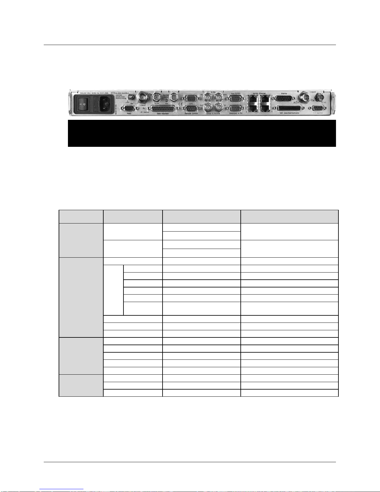
CDM-625 Advanced Satellite Modem Revision 13
Connector Group
(Chapter)
BNC female (70/140MHz band)
Type ’N’ female (L-Band)
Data Interface
25-pin Type ‘D’ female
Serial synchronous data input/output
Balanced G.703
9-pin Type ‘D’ female
G.703, D&I or D&I++; Quad E1 Ports 1 & 2
Auxiliary G.703
9-pin Type ‘D’ female
Quad E1 Ports 3 & 4
Unbalanced Out
BNC female
Receive G.703 (IDO); ASI
Unbalanced In
BNC female
Transmit G.703 (DDI); ASI
IDI
BNC female
Insert Data In / Sub-rate Auxiliary Tx G.703 In
Drop Data Output / Sub-rate Auxiliary Rx
G.703 Out
10/100 Ethernet
(4X) RJ-45 female
10/100 BaseT management and data
IDR Data/Alarms/Audio
44-pin High Density Type ‘D’ female
Intelsat Open Network auxiliary signals
ESC
9-pin Type ‘D’ female
ESC input/output (RS232/485)
Remote Control
9-pin Type ‘D’ male
Serial Remote Interface (RS232/485)
Alarms
15-pin Type ‘D’ male
Form C Alarms (relay closures)
PMSI
9-pin Type ‘D’ female
Pre-Mapped Symbol Interface (CnC)
1:1 Control
9-pin Type ‘D’ female
Connection to External 1:1 Controller
External Reference
BNC female
Input/output
Ground
#10-32 stud – See Sect. 3.3.1
Common Chassis Ground
AC Power (Standard)
See Sect. 3.3.2
Chassis power
DC Power (Optional)
See Sect. 3.3.3
Chassis power
Introduction MN-CDM625
1.3.10.3 Rear Panel
Chapter 3. REAR PANEL CONNECTORS AND PINOUTS
Figure 1-4. CDM-625 Rear Panel View
(Top) Standard AC Chassis (CEFD P/N PL/12587-1)
(Bottom) Optional 48V DC Chassis (CEFD P/N PL/12587-2)
Figure 1-4 shows the rear panel of the modem. External cables are attached to connectors on
the rear panel of the CDM-625. They comprise:
IF
(Sect. 3.2.1)
Terrestrial Data
(Sect. 3.2.2)
Utility
(Sect. 3.2.3
Ground / Power
(Sect 3.3)
Name Connector Type Function
Rx
Tx
G.703
Data
Type ’N’ female (L-Band)
BNC female (70/140MHz band)
DDO BNC female
IF Input
IF Output
The European EMC Directive 2004/108/EEC (EN 55022, EN 50024) requires using
properly shielded cables for DATA I/O. These cables must be double-shielded from
end-to-end, ensuring a continuous ground shield.
1–13
Page 54

CDM-625 Advanced Satellite Modem Revision 13
Modulation
BPSK, QPSK, OQPSK, 8PSK, 8-QAM and 16-QAM
Symbol rate range
18 ksps to 12.5 Msps
Data rate range
18 kbps - 25 Mbps. See Section 1.4.7
Operating frequency
50 - 180 MHz (BNC connector) AND 950 - 2000 MHz (Type N connector), 100 Hz resolution
Stability ±0.06 ppm (±6 x 10⁻⁸) 0 to 50oC (32 to 122oF), when using internal reference
Operating modes
Open Network, per Intelsat IESS-308/309/310/314 (IDR, IBS/SMS)
DoubleTalk® Carrier-in-Carrier® mode (optional plug-in module)
FEC
None: Uncoded BPSK/QPSK/OQPSK
Introduction MN-CDM625
1.4 Summary of Specifications
1.4.1 Modulator
Note: Firmware Ver. 1.4.1 and later increases L-Band range to 950 - 2000 MHz.
E1/T1 Drop and Insert
Transparent, Closed Network, IESS-315 (VSAT Turbo)
Proprietary EDMAC framed mode:
* 5% overhead – EDMAC (data rates < 2.048 Mbps all modes except BPSK Turbo, Rate 21/44 QPSK Turbo)
* 1.6% overhead - EDMAC-2 (rates >2.048 Mbps and all Rate 21/44, 5/16 Turbo)
* EDMAC-3 – for SNMP Proxy – same as EDMAC
R-S Outer Codec
Turbo Product Codec - 2
LDPC Codec (optional plug-in module - includes all 2
VersaFEC
VersaFEC
®
Codec (optional plug-in module – short-block, low latency and ultra-low-latency LDPC)
®
Adaptive Coding and Modulation – IP interface only – maximum symbol rate = 4100 ksps
Automatic Uplink Power Control (AUPC) mode
High Rate ESC, Enhanced ESC (ESC++)
Enhanced Drop & Insert (D&I++)
Quad E1 Drop & Insert (QDI) - concatenates time slots from up to four E1 G.703 streams, Framed QDI
nd
Generation (optional plug-in module)
nd
Generation TPC modes
Viterbi: k=7, per IESS-308/309
BPSK: Rate 1/2
QPSK/OQPSK: Rate 1/2, Rate 3/4 and Rate 7/8
16-QAM: Rate 3/4 and Rate 7/8 (Viterbi plus Reed-Solomon only)
Sequential:
BPSK: Rate 1/2
QPSK/OQPSK: Rate 1/2, Rate 3/4 and Rate 7/8
Reed-Solomon (Open Network):
IDR modes:
225/205 for T1
219/201 for E1 and IESS-310 mode,
194/178 for T2 and E2
IBS modes:
126/112 and 219/201 for IESS-310 mode
Reed-Solomon (Closed Network):
220,200 outer code (transparent mode)
225,205 outer code (transparent mode, EF Data compatible, V.35 scrambling)
126,112 outer code (transparent mode, IBS parameters, D&I++ mode)
219,201 outer code (transparent mode, IESS-310 parameters)
200,180 outer code (EDMAC modes)
Interleaver depth = 4 or 8 (depending on mode)
8PSK/TCM Rate 2/3 (Trellis): Per IESS-310
Turbo Product Codec, 2
Rate 5/16 (2 dimensional) and Rate 21/44 (3-dimensional) BPSK
Rate 21/44 QPSK/OQPSK (aka 1/2) - 3 dimensional
Rate 3/4 QPSK/OQPSK/8PSK/8-QAM/16-QAM - 2 dimensional
Rate 7/8 QPSK/OQPSK/8PSK/8-QAM/16-QAM - 2 dimensional
Rate 0.95 QPSK/OQPSK/8PSK/8-QAM/- 2 dimensional TPC (exact Code Rate is actually 17/18, or 0.944)
Low Density Parity Check (LDPC) Codec (Optional plug-in card):
Rate 1/2 BPSK/QPSK/OQPSK
Rate 2/3 QPSK/OQPSK/8PSK/8-QAM
Rate 3/4 QPSK/OQPSK/8PSK/8-QAM/16-QAM
VersaFEC Codec (Optional plug-in card – short-block, low latency LDPC):
Rate 0.488 BPSK (also 0.493 BPSK Ultra-Low-Latency - requires Firmware 1.5.4 or higher)
Rate 0.533, 0.631, 0.706, 0.803 QPSK (0.493, 0.654, 0.734 Ultra-Low-Latency - requires Firmware 1.5.4 or higher)
Rate 0.642, 0.711, 0.780 8-QAM (also 0.576 8-QAM Extended CCM - requires Firmware 1.5.4 or higher)
Rate 0.731, 0.780, 0.829, 0.853 16-QAM (also 0.644 16-QAM Extended CCM - requires Firmware 1.5.4 or higher)
nd
Generation (Optional plug-in card, includes LDPC modes):
1–14
Page 55
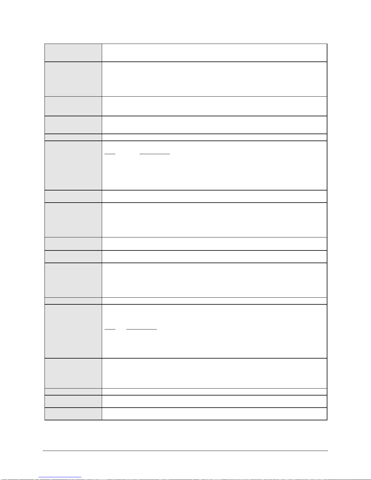
CDM-625 Advanced Satellite Modem Revision 13
Transmit filtering
Firmware prior to 1.4.0: Root-Raised Cosine, alpha = 0.35 (fixed)
Scrambling
IDR Mode, no RS, - per ITU V.35 (Intelsat variant)
External Reference
As an input: 1, 2, 5 or 10MHz -6dBm to +10dBm (nominal 50/75 Ω, BNC female connector)
Harmonics/spurious
Better than -60 dBC/4 kHz (typically <-65 dBC/4kHz)
Transmit on/off ratio
-60 dBC minimum
Output phase noise
< 0.480rms double sided, 100 Hz to 1MHz (minimum of 16 dB better overall than the INTELSAT IESS-308/309 requirement)
The sum of all other single sideband spurious, from 0 to 0.75 x symbol rate, is -48 dBc or lower
Output power
950-2000 MHz band: 0 to -40 dBm, 0.1 dB steps - manual mode. See AUPC section also
50-180 MHz band: 0 to -25 dBm, 0.1 dB steps - manual mode. See AUPC section also
Power accuracy
950-2000 MHz band:
±0.8dB over frequency, data rate, modulation type and temperature range 0 to 50oC
Output impedance
950-2000 MHz band
Output connector
950-2000 MHz band: Type N female
50-180 MHz band: BNC female
Clocking options
Internal, ±0.06 ppm (SCT)
External TX Carrier Off
By TTL 'low' signal or external contact closure - hardware function automatically over-rides processor
BUC Reference
On center conductor of L-Band output connector; 10.0 MHz ± 0.06 ppm (internal reference selected)
-150 100 kHz
BUC Supply Voltage
Standard unit has no BUC supply.
BUC Current Monitor
Min/Max programmable current alarm thresholds.
Tx Carrier ON Delay
Selectable feature power on to allow internal ovenized reference to stabilize before turning on Tx carrier. Intelligent algorithm
BUC Monitoring
Power level, temperature, power class, PLL lock.
Uses ND Satcom/Global VSAT Forum specification for FSK control and monitoring.
Introduction MN-CDM625
Firmware 1.4.0 or later: Root-Raised Cosine, alpha = 0.35 and 0.25 – front panel/software selectable
See graph of output spectrum provided at the end of this section
IBS mode, no RS - per IESS-309, externally frame synchronized
Transparent Closed Network mode, no RS or Turbo coding - per ITU V.35 (Intelsat variant)
EDMAC mode, no RS coding - externally frame synchronized - proprietary
Turbo Product Code/LDPC/VersaFEC modes - externally frame synchronized - proprietary
All RS modes - externally frame synchronized per IESS-308/309/310
As an output: 10MHz, 2.7 volts peak-to-peak ± 0.4 volts, low impedance output
(The Ext. reference phase locks Tx and Rx synthesizers, and all baseband clock generation)
measured from 1 to 500 MHz (50-180 MHz band)
measured F
dB/Hz Frequency Offset
-63.0 100 Hz
-73.0 1 kHz
-83.0 10 kHz
-93.0 100 kHz
Fundamental AC line spurious is -42 dBc or lower
± 500 MHz (950-2000 MHz band)
0
(10 MHz):
Phase Noise
±0.7dB over frequency, data rate, modulation type and temperature range 15 to 35oC
±1.0 dB over frequency, data rate, modulation type and temperature range 0 to 50
50-180 MHz band:
±0.5dB over frequency, data rate, modulation type and temperature range 15 to 35
o
C
o
C
: 50Ω, 19 dB minimum return loss (21 dB typical)
50-180 MHz band: 50Ω, or 75Ω 16 dB minimum return loss (18 dB typical)
External, locking over a ±100 ppm range (TT)
Loop timing (Rx satellite clock) - supports asymmetric operation - Rx and Tx data rates need not be identical
External Clock
G.703 Clock Extension mode – internal ST clock can be slaved to an external T1 or E1 G.703 signal, and a G.703 timing
signal re-constituted at the distant end of the link, regardless of the actual link data rate
0.0 dBm, ± 3 dB; programmable ON/OFF
Source: either Internal Modem Reference or External Reference (10 MHz)
dB/Hz Frequency Offset
-105 10 Hz
-125 100 Hz
-138 1 kHz
-148 10 kHz
Optional BUC Supply:
• 24VDC, 4.17 Amps maximum, 100W
• 48VDC, 3.125 Amps maximum, 150W @ 50
o
C (180 watts @ 30oC)
• Supplied through Tx IF center conductor and selectable ON/OFF via M&C control.
minimizes delay time based on internal temperature at power-up.
1–15
Page 56
CDM-625 Advanced Satellite Modem Revision 13
Input power range,
950-2000 MHz (950-1950 MHz w/Firmware prior to Ver. 1.4.1) band:
Maximum Composite
950-2000 MHz band:
Absolute Maximum,
No Damage
FEC
Viterbi: 3 bit soft decision
VersaFEC: 6 bit soft decision, proprietary
Adaptive Equalizer
5-tap design, selectable on/off
Acquisition range
Programmable in 1kHz increments, and subject to the following:
Above 389 ksymbols/sec: ±1 to ± (0.1Rs) kHz, up to a maximum of ± 200 kHz
Acquisition time
Highly dependent on data rate, FEC rate, and demodulator acquisition range.
decoders to declare synchronization.
Clock tracking range
± 100 ppm min
Clocking modes
Full range of clocking options supported – see plesiochronous/Doppler buffer section
-55
-50
-45
-40
-35
-30
-25
-20
-15
-10
-5
0
0.0 0.1 0.2 0.3 0.4 0.5 0.6 0.7 0.8 0.9 1.0 1.1 1.2 1.3 1.4 1.5
CDM-625
Modulator
typically < -50 dB, and
guaranteed to be
< -45 dB at offsets
> 0.75 Rs
Comtech EF Data
CDM-625 Transmit
Power Spectral
Density, referred to
symbol rate
Symbol Rate, Rs
Spectral
density, dB
Intelsat
IESS
308/309
Limit
Intelsat
IESS
308/309
Limit
Tx Alpha = 0.35
Tx Alpha = 0.25
Note: Tx Alpha = 0.25 requires
Firmware v1.4.0 or higher
Introduction MN-CDM625
1.4.2 Demodulator
Note: Data rate range, operating modes, descrambling, input impedance/return loss etc, as per Sect. 1.4.1 Modulator.
desired carrier
Operating Level
-130 + 10
(symbol rate) to -80 + 10
log
(symbol rate) dBm
log
50-180 MHz band:
-105 + 10
(symbol rate) to -70 + 10
log
(symbol rate) dBm
log
102 – 10 log(symbol rate, desired carrier) dBC, +10 dBm max, with the additional requirement that within ±10 MHz of the
desired carrier, composite power is ≤ +30 dBC.
50-180 MHz band:
94 – 10 log(symbol rate, desired carrier) dBC, +10 dBm max, with the additional requirement that
within ± 10 MHz of the desired carrier, composite power is ≤ +30 dBc
+20 dBm
Sequential: 2 bit soft decision
Trellis: Per IESS-310
Reed-Solomon(Open Network): Per IESS-308/309/310
Reed-Solomon(Closed Network): Proprietary
Turbo Product Codec: 6 bit soft decision, proprietary
LDPC: 5 bit soft decision, proprietary
Below 64 ksymbols/sec: ±1 to ± (Rs/2) kHz, where Rs = symbol rate in ksymbols/sec
Between 64 and 389 ksymbols/sec: ± 1 up to a maximum of ± 32kHz
Examples: 120 ms average at 64 kbps, R1/2 QPSK, ±10 kHz acquisition sweep range, 6dB Eb/No
2 s average at 18 kbps, R1/2 QPSK, ±10 kHz, 6dB Eb/No
Note: The use of Reed-Solomon, TPC, LDPC, VersaFEC increases acquisition time, due to the additional time taken for these
1–16
Page 57

CDM-625 Advanced Satellite Modem Revision 13
LNB 10 MHz Reference
On center conductor of L-Band input connector, selectable ON/OFF. Level: -3dBm ± 3 dB.
reference.
LNB Voltage
On center conductor of L-Band input connector, selectable ON/OFF, 13, 18 volts per DiSEq 4.2 and 24VDC at 500 mA
LNB Current Alarm
Programmable MIN and MAX current alarms.
VITERBI BER performance
Rate 1/2 (B, Q, OQ)
Rate 3/4 (Q, OQ)
Rate 7/8 (Q, OQ)
VITERBI and RS 220,200 or
BER=10-7
Rate 1/2 (B, Q, OQ)
4.5 dB (4.2 dB)
Rate 3/4 (Q, OQ)
6.0 dB (5.2 dB)
Rate 7/8 (Q, OQ)
6.9 dB (6.5 dB)
8PSK/TCM CODEC
Rate 2/3 8PSK/TCM
Rate 2/3 8PSK/TCM
16-QAM VITERBI/
16-QAM Rate 3/4
16-QAM Rate 7/8
SEQUENTIAL at 64 kbps
Rate 1/2 (B, Q, OQ)
Rate 3/4 (Q, OQ)
Rate 7/8 (Q, OQ)
SEQUENTIAL
Rate 1/2 (Q, OQ)
Rate 3/4 (Q, OQ)
Rate 7/8 (Q, OQ)
Introduction MN-CDM625
Source: either Internal modem reference or External reference
Performance: For phase noise, refer to L-Band modulator 10 MHz. Frequency stability same as the modulator 10 MHz
maximum.
(met in the presence of two
adjacent carriers, each 7 dB
higher than the desired carrier)
200,180 Outer Code BER (with
two adjacent carriers, each 7
dB higher than the desired
carrier)
BER (with two adjacent
carriers, each 7 dB higher than
the desired carrier)
220,200 RS BER (with two
adjacent carriers, each 7 dB
higher than the desired carrier)
For:
For:
For:
For:
BER=10
BER=10
BER=10
BER=10
BER=10
BER=10
BER=10
BER=10
BER=10
BER=10
Guaranteed Eb/No:
(typical value in parentheses)
-5
-6
-7
5.4 dB (4.9 dB)
6.0 dB (5.5 dB)
6.7 dB (6.2 dB)
Guaranteed Eb/No:
(typical value in parentheses)
-5
-6
4.3 dB (4.0 dB)
4.4 dB (4.1 dB)
Guaranteed Eb/No:
(typical value in parentheses)
-5
-7
-8
7.9 dB (7.2 dB)
9.5 dB (8.7 dB)
10.4 dB (9.5 dB)
Viterbi/RS
Guaranteed Eb/No:
(typical value in parentheses)
-6
-8
8.1 dB (7.5 dB)
8.6 dB (8.0 dB)
Guaranteed Eb/No:
(typical value in parentheses)
6.8 dB (6.3 dB)
7.4 dB (6.9 dB)
8.2 dB (7.7 dB)
Guaranteed Eb/No:
(typical value in parentheses)
5.6 dB (4.7 dB)
5.8 dB (4.8 dB)
w/concatenated RS
Guaranteed Eb/No:
(typical value in parentheses)
6.3 dB (5.4 dB)
6.7 dB (5.8 dB)
6.9 dB (6.0 dB)
Viterbi/RS
Guaranteed Eb/No:
(typical value in parentheses)
9.5 dB (9.0 dB)
10.1 dB (9.5 dB)
Guaranteed Eb/No:
(typical value in parentheses)
7.7 dB (7.2 dB)
8.4 dB (7.9 dB)
9.0 dB (8.6 dB)
Guaranteed Eb/No:
(typical value in parentheses)
6.5 dB (6.0 dB)
6.7 dB (6.2 dB)
Attention:
For 126,112
Reed-Solomon
Add 0.2 dB to these figures
BER performance (met in the
presence of two adjacent
carriers, each 7 dB higher than
the desired carrier)
at 2048 kbps BER
performance (met in the
presence of two adjacent
carriers, each 7 dB higher than
the desired carrier)
For:
For:
BER=10
BER=10
BER=10
BER=10
BER=10
BER=10
Guaranteed Eb/No:
(typical value in parentheses)
-4
-6
-8
4.4 dB (4.0 dB)
5.1 dB (4.6 dB)
5.7 dB (5.2 dB)
Guaranteed Eb/No:
(typical value in parentheses)
-4
-6
-8
5.0 dB (4.6 dB)
5.8 dB (5.4 dB)
6.7 dB (6.3 dB)
1–17
Guaranteed Eb/No:
(typical value in parentheses)
5.2 dB (4.7 dB)
5.8 dB (5.4 dB)
6.4 dB (6.0 dB)
Guaranteed Eb/No:
(typical value in parentheses)
5.6 dB (5.2 dB)
6.4 dB (6.0 dB)
7.3 dB (6.8 dB)
Guaranteed Eb/No:
(typical value in parentheses)
6.2 dB (5.7 dB)
7.0 dB (6.6 dB)
7.9 dB (7.4 dB)
Guaranteed Eb/No:
(typical value in parentheses)
6.5 dB (6.0 dB)
7.6 dB (7.2 dB)
8.7 dB (8.2 dB)
Page 58

CDM-625 Advanced Satellite Modem Revision 13
SEQUENTIAL and RS 220,200
Rate 1/2 (B, Q, OQ)
Rate 3/4 (Q, OQ)
Rate 7/8 (Q, OQ)
TURBO PRODUCT CODEC
Rate 21/44 (B, Q, OQ)*
Rate 5/16 (B)
TURBO PRODUCT CODEC
Rate 3/4 (Q, OQ)
Rate 3/4 (8PSK, 8-QAM)
Rate 3/4 (16-QAM)
TURBO PRODUCT CODEC
the desired carrier)
Rate 7/8 (Q, OQ)
Rate 7/8 (8PSK, 8-QAM)
Rate 7/8 (16-QAM)
TURBO PRODUCT CODEC
Rate 0.95 (Q, OQ)
Rate 0.95 (8PSK, 8-QAM)
LDPC CODEC BER
* See Note 2
BPSK/QPSK/OQPSK* Rate 1/2
QPSK/OQPSK
QPSK/OQPSK
3.3 dB (3.0 dB)
LDPC CODEC BER
BER=10-9
8PSK Rate 2/3 LDPC
5.7 dB (5.2 dB)
8PSK Rate 3/4 LDPC
6.0 dB (5.6 dB)
Notes:
Introduction MN-CDM625
Outer Code
at 512 kbps
BER performance (with two
adjacent carriers, each 7 dB
higher than the desired carrier)
BER
Rate 21/44 B/Q/OQPSK
Rate 5/16 BPSK
BER (with two adjacent
carriers, each 7 dB higher than
the desired carrier)
BER
Rate 3/4 QPSK
Rate 3/4 8PSK/8-QAM
Rate 3/4 16-QAM
BER (with two adjacent
carriers, each 7 dB higher than
the desired carrier)
BER
Rate 7/8 QPSK
Rate 7/8 8PSK/8-QAM
Rate 7/8 16-QAM
BER (with two adjacent
carriers, each 7 dB higher than
For:
For:
For:
For:
BER=10
BER=10
BER=10
BER=10
BER=10
BER=10
BER=10
BER=10
BER=10
BER=10
BER=10
Guaranteed Eb/No:
(typical value in parentheses)
-4
-6
-8
4.5 dB (4.1 dB)
4.7 dB (4.3 dB)
4.9 dB (4.6 dB)
Guaranteed Eb/No:
(typical value in parentheses)
-6
-7
-8
3.1 dB (2.9 dB)
3.3 dB (3.1 dB)
3.5 dB (3.3 dB)
Guaranteed Eb/No:
(typical value in parentheses)
-6
-7
-8
3.8dB (3.4dB)
4.1dB (3.7dB)
4.4dB (4.0dB)
Guaranteed Eb/No:
(typical value in parentheses)
-5
-8
4.3 dB (4.0 dB)
4.5 dB (4.2 dB)
Guaranteed Eb/No:
(typical value in parentheses)
5.0 dB (4.6 dB)
5.2 dB (4.8 dB)
5.4 dB (5.0 dB)
Guaranteed Eb/No:
(typical value in parentheses)
2.7 dB (2.5dB)
2.9 dB (2.7dB)
3.1 dB (2.9dB)
Guaranteed Eb/No:
(typical value in parentheses)
6.4 dB (6.0 dB)
6.7 dB (6.3 dB)
7.1 dB (6.7 dB)
Guaranteed Eb/No:
(typical value in parentheses)
7.0 dB (6.7 dB)
7.2 dB (6.8 dB)
Guaranteed Eb/No:
(typical value in parentheses)
5.9 dB (5.5 dB)
6.1 dB (5.7 dB)
6.3 dB (5.9 dB)
* See Notes 1 and 2 (below)
Guaranteed Eb/No:
(typical value in parentheses)
7.8 dB (7.4 dB)
8.1 dB (7.7 dB)
8.5 dB (8.2 dB)
Guaranteed Eb/No:
(typical value in parentheses)
8.1 dB (7.7 dB)
8.4 dB (8.1 dB)
BER
Rate 0.95 QPSK
Rate 0.95 8PSK/8-QAM
BER (with two adjacent
carriers, each 7 dB higher than
the desired carrier)
Rate 1/2 B/Q/OQPSK
Rate 2/3 Q/OQPSK
Rate 1/2 Q/OQPSK
(With two adjacent carriers,
each 7 dB higher than the
desired carrier)
Rate 2/3 8PSK
Rate 3/4 8PSK
(With two adjacent carriers,
each 7 dB higher than the
desired carrier)
1) Rate 21/44 QPSK is shown as Rate 1/2 on the Front Panel display, etc.
2) The demod acquisition and tracking threshold for OQPSK is approx 1 dB worse than the QPSK case in this mode.
For:
For:
For:
BER=10
BER=10
BER=10
BER=10
BER=10
BER=10
Guaranteed Eb/No:
(typical value in parentheses)
-6
-7
-8
6.4 dB (6.0 dB)
6.7 dB (6.3 dB)
6.9 dB (6.5 dB)
LDPC
Guaranteed Eb/No:
(typical value in parentheses)
-5
-9
2.0 dB (1.7 dB)
2.3 dB (2.0 dB)
Guaranteed Eb/No:
(typical value in parentheses)
-5
---
Guaranteed Eb/No:
(typical value in parentheses)
9.6 dB (9.2 dB)
10.1 dB (9.7 dB)
10.6 dB (10.2 dB)
Rate 2/3 LDPC
Guaranteed Eb/No:
(typical value in parentheses)
2.3 dB (2.0 dB)
2.7 dB (2.3 dB)
Guaranteed Eb/No:
(typical value in parentheses)
5.6 dB (5.2 dB)
Rate 3/4 LDPC
Guaranteed Eb/No:
(typical value in parentheses)
3.0 dB (2.6 dB)
1–18
Page 59

CDM-625 Advanced Satellite Modem Revision 13
LDPC CODEC BER
8-QAM Rate 2/3 LDPC
8-QAM Rate 3/4 LDPC
LDPC CODEC BER
BER=10-9
16-QAM Rate 3/4 LDPC
7.1 dB (6.8 dB)
VersaFEC CODEC BER
Rate 0.488
VersaFEC CODEC BER
Rate 0.533 QPSK
Rate 0.631 QPSK
Rate 0.706 QPSK
Rate 0.803 QPSK
VersaFEC CODEC BER
BER=10-8
Rate 0.642 8-QAM
4.9 dB (4.6 dB)
Rate 0.711 8-QAM
5.5 dB (5.2 dB)
Rate 0.780 8-QAM
6.0 dB (5.7 dB)
VersaFEC CODEC BER
R 0.731 16-QAM
R 0.780 16-QAM
R 0.829 16-QAM
R 0.853 16-QAM
VersaFEC CODEC - Extended
BER=10-8
R 0.576 8-QAM
4.9 dB (4.6 dB)
R 0.644 16-QAM
6.9 dB (6.6 dB)
Ultra-Low-Latency (ULL)
R 0.493 BPSK
R 0.493 QPSK
R 0.654 QPSK
R 0.734 QPSK
Plesiochronous/
Selectable size of 64 to 262,144 bits, in 16-bit steps (with added limitations for G.704 frame boundaries).
Introduction MN-CDM625
Rate 2/3 8-QAM
Rate 3/4 8-QAM
(With two adjacent carriers,
each 7 dB higher than the
desired carrier)
Rate 3/4 16-QAM
(With two adjacent carriers,
each 7 dB higher than the
desired carrier)
BPSK
(With two adjacent carriers,
each 7 dB higher than the
desired carrier)
QPSK
(With two adjacent carriers,
each 7 dB higher than the
desired carrier)
8-QAM
(With two adjacent carriers,
each 7 dB higher than the
desired carrier)
For:
For:
For:
For:
For:
BER=10-5
BER=10
BER=10
BER=10
BER=10
BER=10
BER=10
BER=10
Guaranteed Eb/No:
(typical value in parentheses)
4.6 dB (4.2 dB)
-9
5.0 dB (4.6 dB)
Guaranteed Eb/No:
(typical value in parentheses)
5.6 dB (5.2 dB)
6.0 dB (5.6 dB)
Guaranteed Eb/No:
(typical value in parentheses)
-5
6.8 dB (6.2 dB)
Guaranteed Eb/No:
(typical value in parentheses)
-5
-8
Guaranteed Eb/No:
(typical value in
-5
-8
2.3 dB (2.0 dB)
2.5 dB (2.2 dB)
Guaranteed Eb/No:
(typical value in
-5
4.6 dB (4.3 dB)
2.4 dB (2.1 dB)
2.7 dB (2.4 dB)
parentheses)
parentheses)
Guaranteed Eb/No:
(typical value in
parentheses)
2.8 dB (2.5 dB)
3.0 dB (2.7 dB)
Guaranteed Eb/No:
(typical value in
parentheses)
5.2 dB (4.9 dB)
Guaranteed Eb/No:
(typical value in
parentheses)
3.3 dB (3.0 dB)
3.7 dB (3.4 dB)
Guaranteed Eb/No:
(typical value in
parentheses)
5.6 dB (5.3 dB)
Guaranteed Eb/No:
(typical value in
parentheses)
3.8 dB (3.5 dB)
4.1 dB (3.8 dB)
16-QAM
(With two adjacent carriers,
each 7 dB higher than the
desired carrier)
CCM BER
(With two adjacent carriers,
each 7 dB higher than the
desired carrier)
CODEC BER
(With two adjacent carriers,
each 7 dB higher than the
desired carrier)
Doppler Buffer
For:
For:
For:
BER=10
BER=10
BER=10
BER=10
BER=10
-5
-8
-5
-5
-8
Guaranteed Eb/No:
(typical value in
parentheses)
6.4 dB (6.1 dB)
6.6 dB (6.3 dB)
Guaranteed Eb/No:
(typical value in
parentheses)
4.5 dB (4.2 dB)
Guaranteed Eb/No:
(typical value in
parentheses)
3.1 dB (2.8 dB)
3.7 dB (3.4 dB)
Guaranteed Eb/No:
(typical value in
parentheses)
7.0 dB (6.7 dB)
7.3 dB (7.0 dB)
Guaranteed Eb/No:
(typical value in
parentheses)
6.4 dB (6.1 dB)
Guaranteed Eb/No:
(typical value in
parentheses)
3.1 dB (2.8 dB)
3.7 dB (3.4 dB)
Guaranteed Eb/No:
(typical value in
parentheses)
7.5 dB (7.2 dB)
7.8 dB (7.5 dB)
Guaranteed Eb/No:
(typical value in
parentheses)
3.6 dB (3.3 dB)
4.2 dB (3.9 dB)
Guaranteed Eb/No:
(typical value in
parentheses)
8.0 dB (7.7 dB)
8.3 dB (8.0 dB)
Guaranteed Eb/No:
(typical value in
parentheses)
4.1 dB (3.8 dB)
4.7 dB (4.4 dB)
Size selection is displayed in bytes and milliseconds.
Supports asymmetric operation - when buffer is clocked from Tx clock, Rx and Tx rates do not need to be identical.
1–19
Page 60
CDM-625 Advanced Satellite Modem Revision 13
Monitor Functions
Eb/No estimate:
-90
-80
-70
-60
-50
-40
-30
-20
-10
0
10 100 1000 10000 100000
Symbol Rate in ksps
Carrier Level in dBm
Maximum
Minimum
-80
-70
-60
-50
-40
-30
-20
-10
0
10
10 100 1000 10000 100000
Symbol Rate in ksps
Carrier Level in dBm
Maximum
Minimum
Introduction MN-CDM625
2 to 10 dB with ± 0.3 dB accuracy
0 to 16 dB with ± 0.5 dB accuracy
Corrected Bit Error Rate, 1E-3 to 1E-10
Frequency offset, ± 32 kHz range, (or 200 kHz range, depending on band and symbol rate) 100 Hz resolution
Buffer fill state, in percent
Receive signal level:
950-2000 MHz band accuracy: ± 3 dB
50-180 MHz band accuracy: ± 2 dB
Figure 1-5. Rx Carrier Level vs. Symbol Rate – L-Band (950-2000 MHz)
Figure 1-6. Rx Carrier Level vs. Symbol Rate – IF Band (50-180 MHz)
1–20
Page 61

CDM-625 Advanced Satellite Modem Revision 13
Primary Data
RS-422/EIA-530 DCE (Rates up to 14 Mbps)
HSSI serial (Rates up to 25 Mbps)
25-pin D-sub (female)
G.703 (Tx In, Drop Out,
1.544 Mbps T1 (Balanced 100 Ω)
Note: All Drop and Insert modes are a FAST option.
9-pin D-sub (female)
ASI
Uses G.703 (Tx In, Rx Out) ports
BNC (female)
Auxiliary G.703
Two additional 2.048 Mbps E1 ports (balanced 120 Ω)
9-pin D-sub (female)
External Reference In/Out
As an input:
BNC (female)
Overhead Data
RS-422 octet clocks for IDR ESC & IBS
44-pin High-density
Modem Alarms
Relay outputs (Tx, Rx & unit faults)
15-pin D-sub (male)
ESC (Overhead)
Standard IBS ESC interfaces
9-pin D-sub (female)
Remote Control
RS-232 or RS-485 modem control and monitoring
9-pin D-sub (male)
PMSI Interface
Pre-mapped Symbol interface
9-pin D-sub (female)
1:1 Control
Control interface for CRS170A/CRS180 1:1 Redundancy unit
9-pin D-sub (male)
Ethernet
4 ports of 10/100 BaseT auto-sensing full/half duplex Ethernet
RJ-45
Introduction MN-CDM625
1.4.3 Data Interfaces
(4 selectable modes)
Insert In, Rx Out)
(used for Quad D&I modes)
IDR BWA
Inputs/Outputs
ADPCM Audio Interface
(also supports X.21 DCE & DTE up to 2.048 Mbps and 8k ESC orderwire for IDR)
V.35 DCE (Rates up to 14 Mbps)
LVDS serial (Rates up to 25 Mbps)
6.312 Mbps T2 (unbalanced 75 Ω or balanced 110 Ω)
2.048 Mbps E1 (unbalanced 75 Ω or balanced 120 Ω)
8.448 Mbps E2 (unbalanced 75 Ω)
Note: All Drop and Insert modes are a FAST option.
1, 2, 5 or 10MHz -6dBm to +10dBm (nominal 50/75 Ω)
As an output:
10MHz, 2.7 volts peak-to-peak +/- 0.4 volts, low impedance output
RS-422 IDR 64 kbps ESC data & clock
IDR BWA Inputs/4 backward alarm Form C relay outputs
2 audio channels, each occupying 32 kbps bandwidth as part of IDR overhead or as
a 64 kbps primary data rate option.
600 Ω balanced – 0 dBm0 nominal, -6 to +8 dB, 2 dB steps
or BNC (female)
D-sub (male)
Demodulator I & Q test outputs (constellation)
Demodulator Rx Signal Level output (0 to 2.5 volts)
External carrier off input
RS-232/485 High Rate ESC data
RS-232/485 ESC++ data
(used by DoubleTalk Carrier-in-Carrier function)
1–21
Page 62
CDM-625 Advanced Satellite Modem Revision 13
Operating Mode
Requires Closed Network Framed mode (EDMAC, D&I++, Enhanced D&I, or ESC++) for transport of
Eb/No information from remote modem (EDMAC can be enabled or disabled)
Monitor functions
(front panel or via remote control interface)
Requires the two links to share a common carrier frequency (Outbound and Inbound symbol rates do
not have to be equal)
BSPK/QPSK/8PSK/8-QAM: –7 dB to +11 dB (ratio of power spectral density, outbound interferer to
Absolute power ratio (CnC Ratio) = +7dB + (10 log Outbound/desired symbol rate) = +10 dB
an additional 0.3 dB
Monitor Functions
Delay, in milliseconds
Power Spectral Density Ratio, in 0.1 dB
Introduction MN-CDM625
1.4.4 Automatic Uplink Power Control (AUPC)
Target Eb/No range 0 to 14.9 dB at remote demod (default is 4.0 dB)
Max AUPC range 0 to 9 dB (default is 3 dB)
Remote demod Eb/No
Tx power level increase
1.4.5 DoubleTalk® Carrier- in-Carrier® (CnC)
Operating Mode
Power Spectral Density Ratio and
CnC Ratio
Maximum Symbol Rate Ratio 3:1 (TX:RX or RX:TX)
Inbound/Outbound frequency
uncertainty
Delay range 0-330 ms
Eb/No Degradation
(equal Inbound/Outbound power
spectral density)
desired inbound)
16-QAM: –7 dB to +7 dB (ratio of power spectral density, outbound interferer to desired inbound)
Note: With asymmetric carriers, the absolute power ratio (or CnC ratio) would be different,
depending on the ratio of the symbol rates.
Example:
Outbound interferer = 1 Msymbols/sec
Desired Inbound = 500 ksymbols/sec
Ratio of power spectral density = +7 dB
Within the normal acquisition range of the demod, as follows:
Below 64 ksymbols/sec: ±1 to ± (Rs/2) kHz, where Rs = symbol rate in ksymbols/sec
Between 64 and 389 ksymbols/sec: ± 1up to a maximum of ± 32kHz
Above 389 ksymbols/sec: ±1 to ± (0.1Rs) kHz, up to a maximum of ± 200 kHz
BPSK = 0.3dB QPSK = 0.3dB OQPSK = 0.3dB
8PSK = 0.5dB 8-QAM = 0.4dB 16-QAM = 0.6dB
For +10 dB power spectral density ratio (outbound interferer 10 dB higher than desired inbound) add
Frequency offset (between outbound interferer and desired inbound). 100 Hz resolution
CnC Power Ratio, in 0.1 dB (ratio of absolute power, outbound interferer to desired inbound)
CnC Monitor Accuracy ±0.1 dB for symmetric symbol rate
1–22
Page 63

CDM-625 Advanced Satellite Modem Revision 13
Available data rates
Overhead
Additional Reed-
Scrambling
200/220
126/112
To 2 Mbps: 5%
(see Note 2)
Remote control link
processor plus AUPC
Remote control link
processor plus AUPC
Remote control link
processor plus AUPC
EIA-422 ESC
EIA-232 Earth station
BW alarm
EIA-232 Earth station
One BW alarm
1/45 of front panel data
T1 or E1
Same as EDMAC, plus
primary data rate
Variable: between
1.58% above 7 Mbps
EIA-232 Earth station
plus AUPC
n x 64 kbps, up to
n x 64 kbps, up to
D&I interfaces
% for Rates 5/16 or 21/44 BPSK Turbo, Rate 1/2 QPSK/OQPSK Turbo, and all rates > 2 Mbps.
Introduction MN-CDM625
1.4.6 Framing Summary
Framing Mode Overhead added
Transparent None All rates and formats None
EDMAC
EDMAC-2 1.6% All rates and formats
EDMAC-3
IDR Fixed 96 kHz
IBS
D&I
Above 2 Mbps: 1.6%
To 2 Mbps: 5%
Above 2 Mbps: 1.6%
1/15 of front panel data
rate
1/15 of front panel data
rate
Terrestrial is T1 or E1
and format
All rates and formats
All rates and formats
T1, E1, T2 and E2; all
formats
64 to 2048 kbps only;
all formats
Specific multiples of 64
kbps only
between modems’
between modems’
between modems’
(8 kbps)
EIA-422 ESC
(64 kbps or
2 audio links)
4 BW alarms
link at 1/480th of
primary data rate. One
link at 1/480th of
primary data rate
components
Solomon Overhead
225/205
219/201
200/180 Proprietary scrambler
200/180 Proprietary scrambler
200/180 Proprietary scrambler
T1 = 225/205
E1 = 219/201 and
IESS-310 mode
T2/E2 = 194/178
126/112
219/201 for IESS-310
mode
126/112
219/201 for IESS-310
mode
(see Note 1)
Basic ITU
V.35 (Intelsat)
Basic ITU V.35
(Intelsat)
IESS-309 scrambler
IESS-309 scrambler
D&I++
ESC++
QDI
Framed QDI
rate
Terrestrial is
11.76% at 64 kbps to
0.78% (129/128) of
front panel data rate
Concatenation of QDI
and EDMAC-2
Notes:
1. Reed-Solomon is Off.
2.
Any multiple of 64 kbps,
up to n = 31
All rates and formats
n = 128 using a max of
4 balanced G.703 E1
D&I interfaces
n = 128 using a max of
4 balanced G.703 E1
EIA-232 Earth station
link at 1/576
link at variable rate,
None
None 200/180
th
of
126/112
126/112
220/200
225/205
219/201
Basic ITU V.35
(Intelsat)
Basic ITU V.35
(Intelsat)
Basic ITU V.35
(Intelsat)
Basic ITU V.35
(Intelsat)
1–23
Page 64
CDM-625 Advanced Satellite Modem Revision 13
UNFRAMED (NO REED SOLOMON)
Lower Limit (kbps)
Upper Limit (kbps)
No FEC, BPSK
18.0
12500
No FEC, O/QPSK
36.0
25000.0
VITERBI, BPSK, 1/2
18.0
6250.0
VITERBI, O/QPSK, 1/2
18.0
12500.0
VITERBI, O/QPSK, 3/4
27.0
18750.0
VITERBI, O/QPSK, 7/8
31.5
21875.0
SEQUENTIAL, BPSK, 1/2
18.0
1024.0
SEQUENTIAL, O/QPSK, 1/2
18.0
2048.0
SEQUENTIAL, O/QPSK, 3/4
27.0
2048.0
SEQUENTIAL, O/QPSK, 7/8
31.5
2048.0
TRELLIS, 8PSK, 2/3
36.0
25000.0
TPC, BPSK, 5/16
18.0
3906.2
TPC, BPSK, 21/44 (aka 1/2)
18.0
5965.9
TPC, O/QPSK, 21/44 (aka 1/2)
18.0
11931.8
TPC, O/QPSK, 3/4
27.0
18750.0
TPC, O/QPSK, 17/18 (aka 0.95)
34.2
23611.1
TPC, O/QPSK, 7/8
31.5
21875.0
TPC, 8PSK/8-QAM, 3/4
40.5
25000.0
TPC, 8PSK/8-QAM, 17/18 (aka 0.95)
52.0
25000.0
TPC, 8PSK/8-QAM, 7/8
48.0
25000.0
TPC, 16-QAM, 3/4
54.0
25000.0
TPC, 16-QAM, 7/8
63.0
25000.0
LDPC, BPSK, 1/2
18.0
6250.0
LDPC, O/QPSK, 1/2
18.0
12500.0
LDPC, O/QPSK, 3/4
27.0
18750.0
LDPC, O/QPSK, 2/3
24.0
16666.6
LDPC, 8PSK/8-QAM, 3/4
40.5
25000.0
LDPC, 8PSK/8-QAM, 2/3
36.0
25000.0
LDPC, 16-QAM, 3/4
54.0
25000.0
UNFRAMED (ANY REED SOLOMON)
Lower Limit (kbps)
Upper Limit (kbps)
VITERBI, BPSK, 1/2
18.0
5555.0
VITERBI, O/QPSK, 1/2
18.0
11111.0
VITERBI, O/QPSK, 3/4
27.0
16666.6
VITERBI, O/QPSK, 7/8
31.5
19444.0
SEQUENTIAL, BPSK, 1/2
18.0
1024.0
SEQUENTIAL, O/QPSK, 1/2
18.0
2048.0
SEQUENTIAL, O/QPSK, 3/4
29.0
2048.0
SEQUENTIAL, O/QPSK, 7/8
31.5
2048.0
TRELLIS, 8PSK, 2/3
36.0
22222.0
VIT 16-QAM, 3/4
54.0
22222.0
VIT 16-QAM, 7/8
63.0
22222.0
Introduction MN-CDM625
1.4.7 Data Rate Ranges
1–24
Page 65

CDM-625 Advanced Satellite Modem Revision 13
EDMAC, EDMAC-2, or EDMAC-3 (NO REED SOLOMON)
Lower Limit (kbps)
Upper Limit (kbps)
No FEC, BPSK
18.0
12295.0
No FEC, O/QPSK
35.5
24590.1
VITERBI, BPSK, 1/2
18.0
6147.5
VITERBI, O/QPSK, 1/2
18.0
12295.0
VITERBI, O/QPSK, 3/4
26.6
18442.6
VITERBI, O/QPSK, 7/8
31.0
21516.3
SEQUENTIAL, BPSK, 1/2
18.0
1024.0
SEQUENTIAL, O/QPSK, 1/2
18.0
2048.0
SEQUENTIAL, O/QPSK, 3/4
26.6
2048.0
SEQUENTIAL, O/QPSK, 7/8
31.0
2048.0
TRELLIS, 8PSK, 2/3
35.5
24590.1
TPC, BPSK, 5/16
18.0
3842.2
TPC, BPSK, 21/44 (aka 1/2)
18.0
5868.1
TPC, O/QPSK, 21/44 (aka 1/2)
18.0
11736.2
TPC, O/QPSK, 3/4
26.6
18442.6
TPC, O/QPSK, 17/18 (aka 0.95)
33.5
23224.0
TPC, O/QPSK, 7/8
31.0
21516.3
TPC, 8PSK/8-QAM, 3/4
39.9
24590.1
TPC, 8PSK/8-QAM, 17/18 (aka 0.95)
50.2
24590.1
TPC, 8PSK/8-QAM, 7/8
46.5
24590.1
TPC, 16-QAM, 3/4
53.2
24590.1
TPC, 16-QAM, 7/8
62.0
24590.1
LDPC, BPSK, 1/2
18.0
6147.5
LDPC, O/QPSK, 1/2
18.0
12295.0
LDPC, O/QPSK, 3/4
26.6
18442.6
LDPC, O/QPSK, 2/3
23.7
16393.4
LDPC, 8PSK/8-QAM, 3/4
39.9
24590.1
LDPC, 8PSK/8-QAM, 2/3
35.5
24590.1
LDPC, 16-QAM, 3/4
53.2
24590.1
EDMAC, EDMAC-2, or EDMAC-3 (ANY REED SOLOMON)
Lower Limit (kbps)
Upper Limit (kbps)
VITERBI, BPSK, 1/2
18.0
5532.7
VITERBI, O/QPSK, 1/2
18.0
11065.5
VITERBI, O/QPSK, 3/4
24.0
16598.3
VITERBI, O/QPSK, 7/8
27.9
19364.7
SEQUENTIAL, BPSK, 1/2
18.0
1024.0
SEQUENTIAL, O/QPSK, 1/2
18.0
2048.0
SEQUENTIAL, O/QPSK, 3/4
24.0
2048.0
SEQUENTIAL, O/QPSK, 7/8
27.9
2048.0
TRELLIS, 8PSK, 2/3
31.9
22131.1
VIT 16-QAM, 3/4
47.9
22131.1
VIT 16-QAM, 7/8
55.8
22131.1
IBS (NO REED SOLOMON)
Lower Limit (kbps)
Upper Limit (kbps)
No FEC, BPSK
64.0
8448.0
No FEC, O/QPSK
64.0
8448.0
Introduction MN-CDM625
1–25
Page 66

CDM-625 Advanced Satellite Modem Revision 13
VITERBI, BPSK, 1/2
64.0
5859.3
VITERBI, O/QPSK, 1/2
64.0
8448.0
VITERBI, O/QPSK, 3/4
64.0
8448.0
VITERBI, O/QPSK, 7/8
64.0
8448.0
SEQUENTIAL, BPSK, 1/2
64.0
1024.0
SEQUENTIAL, O/QPSK, 1/2
64.0
2048.0
SEQUENTIAL, O/QPSK, 3/4
64.0
2048.0
SEQUENTIAL, O/QPSK, 7/8
64.0
2048.0
TRELLIS, 8PSK, 2/3
64.0
8448.0
TPC, BPSK, 5/16
64.0
3662.1
TPC, BPSK, 21/44 (aka 1/2)
64.0
5593.0
TPC, O/QPSK, 21/44 (aka 1/2)
64.0
8448.0
TPC, O/QPSK, 3/4
64.0
8448.0
TPC, O/QPSK, 17/18 (aka 0.95)
64.0
8448.0
TPC, O/QPSK, 7/8
64.0
8448.0
TPC, 8PSK/8-QAM, 3/4
64.0
8448.0
TPC, 8PSK/8-QAM, 17/18 (aka 0.95)
64.0
8448.0
TPC, 8PSK/8-QAM, 7/8
64.0
8448.0
TPC, 16-QAM, 3/4
64.0
8448.0
TPC, 16-QAM, 7/8
64.0
8448.0
LDPC, BPSK, 1/2
64.0
5859.3
LDPC,O/ QPSK, 1/2
64.0
8448.0
LDPC, O/QPSK, 3/4
64.0
8448.0
LDPC, O/QPSK, 2/3
64.0
8448.0
LDPC, 8PSK/8-QAM, 3/4
64.0
8448.0
LDPC, 8PSK/8-QAM, 2/3
64.0
8448.0
LDPC, 16-QAM, 3/4
64.0
8448.0
IBS (ANY REED SOLOMON)
Lower Limit (kbps)
Upper Limit (kbps)
VITERBI, BPSK, 1/2
64.0
5208.0
VITERBI, O/QPSK, 1/2
64.0
8448.0
VITERBI, O/QPSK, 3/4
64.0
8448.0
VITERBI, O/QPSK, 7/8
64.0
8448.0
SEQUENTIAL, BPSK, 1/2
64.0
1024.0
SEQUENTIAL, O/QPSK, 1/2
64.0
2048.0
SEQUENTIAL, O/QPSK, 3/4
64.0
2048.0
SEQUENTIAL, O/QPSK, 7/8
64.0
2048.0
TRELLIS, 8PSK, 2/3
64.0
8448.0
VIT 16-QAM, 3/4
64.0
8448.0
VIT 16-QAM, 7/8
64.0
8448.0
ESC++ (NO REED SOLOMON)
Lower Limit (kbps)
Upper Limit (kbps)
No FEC, BPSK
64.0
12304.6
No FEC, O/QPSK
64.0
24609.3
VITERBI, BPSK, 1/2
64.0
5921.0
VITERBI, O/QPSK, 1/2
64.0
12304.6
VITERBI, O/QPSK, 3/4
64.0
18457.0
Introduction MN-CDM625
1–26
Page 67

CDM-625 Advanced Satellite Modem Revision 13
VITERBI, O/QPSK, 7/8
64.0
21533.2
SEQUENTIAL, BPSK, 1/2
64.0
1024.0
SEQUENTIAL, O/QPSK, 1/2
64.0
2048.0
SEQUENTIAL, O/QPSK, 3/4
64.0
2048.0
SEQUENTIAL, O/QPSK, 7/8
64.0
2048.0
TRELLIS, 8PSK, 2/3
64.0
24609.3
TPC, BPSK, 5/16
64.0
3700.6
TPC, BPSK, 21/44 (aka 1/2)
64.0
5651.9
TPC, O/QPSK, 21/44 (aka 1/2)
64.0
11745.3
TPC, O/QPSK, 3/4
64.0
18457.0
TPC, O/QPSK, 17/18 (aka 0.95)
64.0
23242.1
TPC, O/QPSK, 7/8
64.0
21533.2
TPC, 8PSK/8-QAM, 3/4
64.0
24609.3
TPC, 8PSK/8-QAM 17/18 (aka 0.95)
64.0
24609.3
TPC, 8PSK/8-QAM, 7/8
64.0
24609.3
TPC, 16-QAM, 3/4
64.0
24609.3
TPC, 16-QAM, 7/8
64.0
24609.3
LDPC, BPSK, 1/2
64.0
5921.0
LDPC, O/QPSK, 1/2
64.0
12304.6
LDPC, O/QPSK, 3/4
64.0
18457.0
LDPC, O/QPSK, 2/3
64.0
16406.2
LDPC, 8PSK/8-QAM, 3/4
64.0
24609.3
LDPC, 8PSK/8-QAM,2/3
64.0
24609.3
LDPC, 16-QAM, 3/4
64.0
24609.3
ESC++ (ANY REED SOLOMON)
Lower Limit (kbps)
Upper Limit (kbps)
VITERBI, BPSK, 1/2
64.0
5263.1
VITERBI, O/QPSK, 1/2
64.0
10937.5
VITERBI, O/QPSK, 3/4
64.0
16406.2
VITERBI, O/QPSK, 7/8
64.0
19140.6
SEQUENTIAL, BPSK, 1/2
64.0
1024.0
SEQUENTIAL, O/QPSK, 1/2
64.0
2048.0
SEQUENTIAL, O/QPSK, 3/4
64.0
2048.0
SEQUENTIAL, O/QPSK, 7/8
64.0
2048.0
TRELLIS, 8PSK, 2/3
64.0
21875.0
VITERBI, 16-QAM, 3/4
64.0
21875.0
VITERBI, 16-QAM, 7/8
64.0
21875.0
VersaFEC (ANY MODE)
Lower Limit (kbps)
Upper Limit (kbps)
VersaFEC BPSK Rate 0.488
18.0
5700.0
VersaFEC QPSK Rate 0.533
20.0
10000.0
VersaFEC QPSK Rate 0.631
23.0
10000.0
VersaFEC QPSK Rate 0.706
26.0
10000.0
VersaFEC QPSK Rate 0.803
28.0
12000.0
VersaFEC 8-QAM Rate 0.576 (ECCM)
32.0
11000.0
VersaFEC 8-QAM Rate 0.642
35.0
12000.0
VersaFEC 8-QAM Rate 0.711
39.0
12000.0
Introduction MN-CDM625
1–27
Page 68
CDM-625 Advanced Satellite Modem Revision 13
VersaFEC 8-QAM Rate 0.780
43.0
12000.0
VersaFEC 16-QAM Rate 0.644 (ECCM)
47.0
11000.0
VersaFEC 16-QAM Rate 0.731
53.0
12000.0
VersaFEC 16-QAM Rate 0.780
57.0
14000.0
VersaFEC 16-QAM Rate 0.829
60.0
14000.0
VersaFEC 16-QAM Rate 0.853
62.0
16000.0
ULL BPSK Rate 0.493
18.0
5700.0
ULL QPSK Rate 0.493
18.0
6000.0
ULL QPSK Rate 0.654
24.0
9000.0
ULL QPSK Rate 0.734
27.0
9000.0
VersaFEC Adaptive Coding and Modulation (ACM): See Specifications that follow (Sect.1.4.8)
Introduction MN-CDM625
1–28
Page 69
CDM-625 Advanced Satellite Modem Revision 13
Switch point
Introduction MN-CDM625
1.4.8 VersaFEC Adaptive Coding and Modulation (ACM)
System type
Symbol Rate Range 37 ksps to 4100 ksps
Interface 10/100 Base T Ethernet, with auto-negotiated Congestion Control
Remote SNR reporting
Max span of data rate 7:1 over range of adaptation
(decreasing SNR)
Switch point hysteresis 0.3 dB
Max fading rate Approximately 1 dB/second (higher if Target Eb/No margin > 1 dB)
Max ModCod update rate 1 update every 2 seconds (no restriction on distance between ModCods)
Configurable parameters
System latency
Monitored parameters
Adaptive Coding and Modulation, using BPSK, QPSK, 8-QAM , 16-QAM and
VersaFEC short-block LDPC coding - total of 12 ModCods
Automatically reported from remote modem – built in function at the physical
layer – requires no additional overhead
Corresponds to SNR (Eb/No) that gives BER = 5 x 10⁻⁸
Minimum and Maximum ModCod (ModCod0 through ModCod11)
Remote Demod Unlock Action: Maintain current ModCod
Go to minimum ModCod
Target Eb/No margin (0 to 4.5 dB, 0.5 dB steps)
54 milliseconds max (for a system operating at 100 ksps, and assuming a WAN
buffer of 20 milliseconds, not including satellite path)
Tx and Rx ModCods
Local and Remote SNR
(-3.0 dB to +22.0dB, 0.1dB resolution, +/- 0.5 dB accuracy)
Config and monitor menus displaying data rate, modulation and code rate update
dynamically with ModCod
Modulation Code Rate
BPSK 0.488 0.49 2.4 dB 18.1 kbps 2.00 Mbps
QPSK 0.533 1.07 2.2 dB 39.6 kbps 4.38 Mbps
QPSK 0.631 1.26 2.7 dB 46.7 kbps 5.16 Mbps
QPSK 0.706 1.41 3.4 dB 52.2 kbps 5.78 Mbps
QPSK 0.803 1.61 3.8 dB 59.6 kbps 6.60 Mbps
8-QAM 0.642 1.93 4.6 dB 71.5 kbps 7.91 Mbps
8-QAM 0.711 2.13 5.2 dB 78.8 kbps 8.73 Mbps
8-QAM 0.780 2.34 5.6 dB 86.6 kbps 9.59 Mbps
16-QAM 0.731 2.93 6.3 dB 108.5 kbps 12.01 Mbps
16-QAM 0.780 3.12 7.0 dB 115.5 kbps 12.79 Mbps
16-QAM 0.829 3.32 7.5 dB 122.8 kbps 13.61 Mbps
16-QAM 0.853 3.41 8.0 dB 126.2 kbps 14.00 Mbps
Spectral efficiency,
bps/Hz
Typical
Eb/No, for
BER = 5 x 10
-8
Min. Data
Rate,
ACM mode
Max. Data
Rate,
ACM mode
1–29
Page 70
CDM-625 Advanced Satellite Modem Revision 13
Front Panel
Tactile keypad, 6 keys (Up/Down), Left/Right, Enter/Clear)
Vacuum Fluorescent Display (blue) – 2 lines of 40 characters
Loopbacks
Internal IF loopback, RF loopback, digital loopback, and inward/outward loopback
Fault relays
Weight
10.5 lbs (4.8 kg) max (All option cards and 48V BUC supply installed)
280 watts (typical TPC/LDPC Codec, CnC module and 48 volt BUC supply installed, 300 watts (max)
90 – 264 VAC Maximum
DC consumption (option)
As above (AC consumption)
DC operating voltage
43-60 VDC Nominal
36 – 60 VDC Maximum
Operating temperature
0 to 50ºC (32 to 122ºF)
EN 61000-4-6
Introduction MN-CDM625
1.4.9 Miscellaneous
Hardware fault, Rx and Tx Traffic Alarms, Open Network Backward Alarms
Type: Form C Contacts. Rating: Up to +/-50 volts, max 0.5 Amp
M&C Interface EIA-232 and EIA-485 (addressable multidrop, 2-wire or 4-wire) or Ethernet (10/100 BaseT)
M&C Software Serial comms, SNMP, Telnet, Web Server (HTTP)
Firmware update Via Ethernet port. ftp protocol
Dimensions 1RU high, 17.65 inches (448 mm) deep
AC consumption 48 watts (typical, TPC/LDPC Codec and CnC module installed), 68watts (maximum)
AC operating voltage 100 - 240 VAC Nominal - autosensing
1.4.10 Approvals
“CE” as follows:
FCC
EN 55022 Class B
(Emissions)
EN 50082-1 (Immunity)
EN 60950-1 (Safety)
Federal Communications Commission Federal Code of Regulation FCC Part 15, Subpart B.
EN 61000-3-2
EN 61000-3-3
EN 61000-4-2
EN 61000-4-4
EN 61000-4-5
EN 61000-4-8
EN 61000-4-9
EN 61000-4-11
EN 61000-4-13
1–30
Page 71

Chapter 2. INSTALLATION
This equipment contains parts and assemblies sensitive to damage by Electrostatic
2.1 Unpacking and Inspecting the Shipment
Figure 2-1. Unpacking and Inspecting the CDM-625
The CDM-625 Advanced Satellite Modem, its Installation and Operation Manual, and its power
cord were packaged and shipped in a reusable cardboard carton containing protective foam
spacing.
Discharge (ESD). Use ESD precautionary procedures when handling the equipment.
2–1
Page 72

CDM-625 Advanced Satellite Modem Revision 13
PROPER GROUNDING PROTECTION IS REQUIRED. The equipment must be
PROPER AIR VENTILATION IS REQUIRED. In a rack system where there is high
°
For information about custom rack enclosures, contact Comtech EF Data
Step
Task
Inspect the equipment for any possible damage incurred during shipment.
damage is evident to the shipment.
4
Review
5
Proceed to Sect. 2.2 Installing and Mounting the CDM-625
Installation MN-CDM625
As shown in Figure 2-1: Once opened, inspect the shipment:
1 Keep all shipping materials for storage or reshipment.
2 Check the packing list to ensure the shipment is complete.
3
Contact the carrier and Comtech EF Data immediately and submit a damage report if
the manual carefully to become familiar with operation.
2.2 Installing Into a Rack Enclosure
When mounting the CDM-625 into a rack enclosure (Figure 2-1):
•
connected to the protective earth connection at all times. It is therefore imperative
that the unit is properly grounded, using the ground stud provided on the unit rear
panel, during installation, configuration, and operation.
• In Finland: "Laite on liitettävä suojamaadoituskoskettimilla varustettuun
pistorasiaan."
• In Norway: “Apparatet må tilkoples jordet stikkontakt.”
• In Sweden: “Apparaten skall anslutas till jordat uttag.”
•
heat discharge, provide forced-air cooling with top- or bottom-mounted fans or
blowers.
o Make sure there is adequate clearance inside the enclosure, especially at
the side for air ventilation.
o Air temperature inside the rack enclosure should never exceed 50°C
F).
(122
Customer Support during normal business hours or visit Comtech EF Data’s Web
site (
www.comtechefdata.com/support.asp).
2–2
Page 73

CDM-625 Advanced Satellite Modem Revision 13
•
625 CANNOT have rack slides mounted to the sides of the chassis.
impeded. Comtech EF Data recommends that an alternate method of support is
Mounting Support Bracket Kit. If there is any doubt, contact Comtech EF Data
Rack Enclosure Threaded Front
Mounting Rail (typical)
Installation MN-CDM625
The CDMCooling fans and exhaust vents are provided here – air flow must not be
provided within the rack, such as standard rack shelves or the optional Rear-
Customer Support during normal business hours.
Feature Description
1 Custom Rack Enclosure
2 CDM-625 Advanced Satellite Modem
3 Standard Rack Shelving
4
5 Unit Front Panel
6 User-supplied Screws
Figure 2-2. Installing the CDM-625 Into a Rack Enclosure
Mount the CDM-625 in its assigned position in the rack enclosure. Use, as required:
• A standard rack-mounted shelf;
• User-supplied screws to secure the front panel to the rack enclosure threaded front
mounting rails;
• Comtech EF Data’s optional KT/6228 (4”) or KT/6228 (10”) Rear-Mounting Support
Brackets Kit (Figure 2-3).
2–3
Page 74
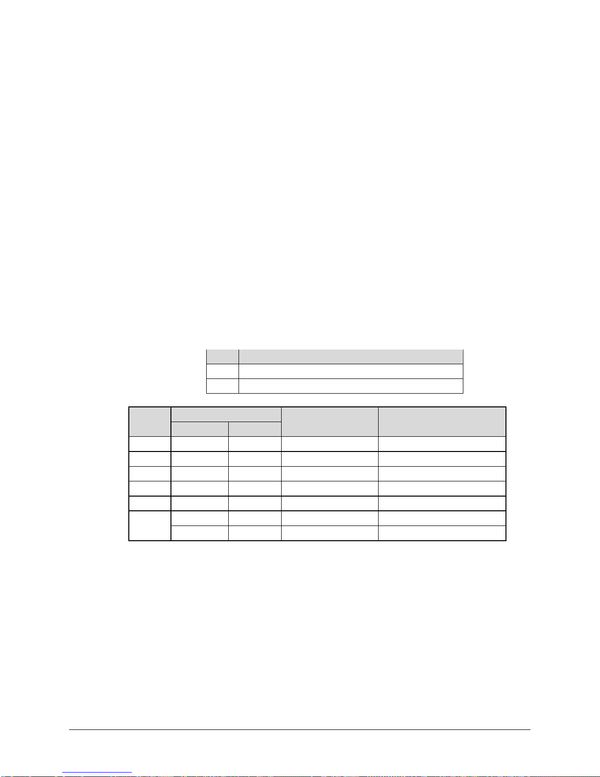
CDM-625 Advanced Satellite Modem Revision 13
Installation MN-CDM625
2.2.1 Installing the Optional Rear-Mounting Support Brackets Kits
Detail Description
1 Back of modem
2 Rack Enclosure Threaded Rear Mounting Rail (typical)
Item
1 2 2 HW/10-32SHLDR Shoulder Screw, #10
2 4 4 HW/10-32FLT Flat Washer, #10
3 2 2 HW/10-32SPLIT Lock Washer, #10
4 2 2 HW/10-32HEXNUT Hex Nut, #10
5 4 4 HW/10-32x1/2RK Bolt, #10, Rear Support Bracket
6
Kit / Quantity
KT/6228-2 KT/6228-3
2 – FP/6138-2 Bracket, Rear Support – 4”
– 2 FP/6138-3 Bracket, Rear Support – 10”
CEFD P/N Description
Figure 2-3. Installing the Optional Rear-Mounting Support Brackets Kit
Tools needed to install the optional KT/6228 (4”) or KT/6228 (10”) Rear-Mounting Support
Brackets Kit:
• A medium Phillips screwdriver
• A 5/32-inch SAE Allen Wrench
• An adjustable Crescent wrench.
2–4
Page 75

CDM-625 Advanced Satellite Modem Revision 13
Step
Task
Use the #10 flat washers, #10 split washers, and #10 hex nut to secure the #10 shoulder screws to the unit
Use the #10 rack bracket bolts to install the rear support brackets onto the rack enclosure threaded rear
mounting rails.
Mount the unit into the rack enclosure. Ensure that the shoulders of the #10 shoulder screws properly engage
into the rear support bracket slots.
Installation MN-CDM625
Follow these steps to install the optional KT/6228 (4”) or KT/6228 (10”) Rear-Mounting Support
Brackets Kit:
1
chassis through the rear right and left side mounting slots as shown.
2
3
2.3 Configuring the CDM-625
Chapter 5. FRONT PANEL OPERATION
The unit is shipped with a default 64 kbps, QPSK, Rate 1/2 configuration. There are no internal
jumpers to configure, no interface cards to install, and no other options to install. All
configurations are carried out entirely via the modem’s installed firmware – use the front panel
keypad and display to configure the modem locally.
The auto-sensing AC power supply does not require any adjustments. Simply plug
in the supplied line cord, and turn on the rear panel switch.
2.4 Selecting the Internal IF Loop
Chapter 5. FRONT PANEL OPERATION – Sect. 5.2.2 SELECT: Test Menus
You may quickly verify proper operation of the modem without the need for externally
connected equipment. From the top level menu, select TEST: Mode →
should synchronize, and the Rx TRAFFIC LED should illuminate GREEN. If the unit does not pass
this test, call Comtech EF Data’s Customer Support department for assistance.
2.5 Connecting the External Cables
Chapter 3. REAR PANEL CONNECTORS AND PINOUTS
Having verified correct operation via the Internal IF loop test, enter the desired configuration
and then connect all external cables. If difficulties occur, call Comtech EF Data’s Customer
Support department for assistance.
IF↓ (IF LOOP).The demod
2–5
Page 76

CDM-625 Advanced Satellite Modem Revision 13
Installation MN-CDM625
Notes:
2–6
Page 77
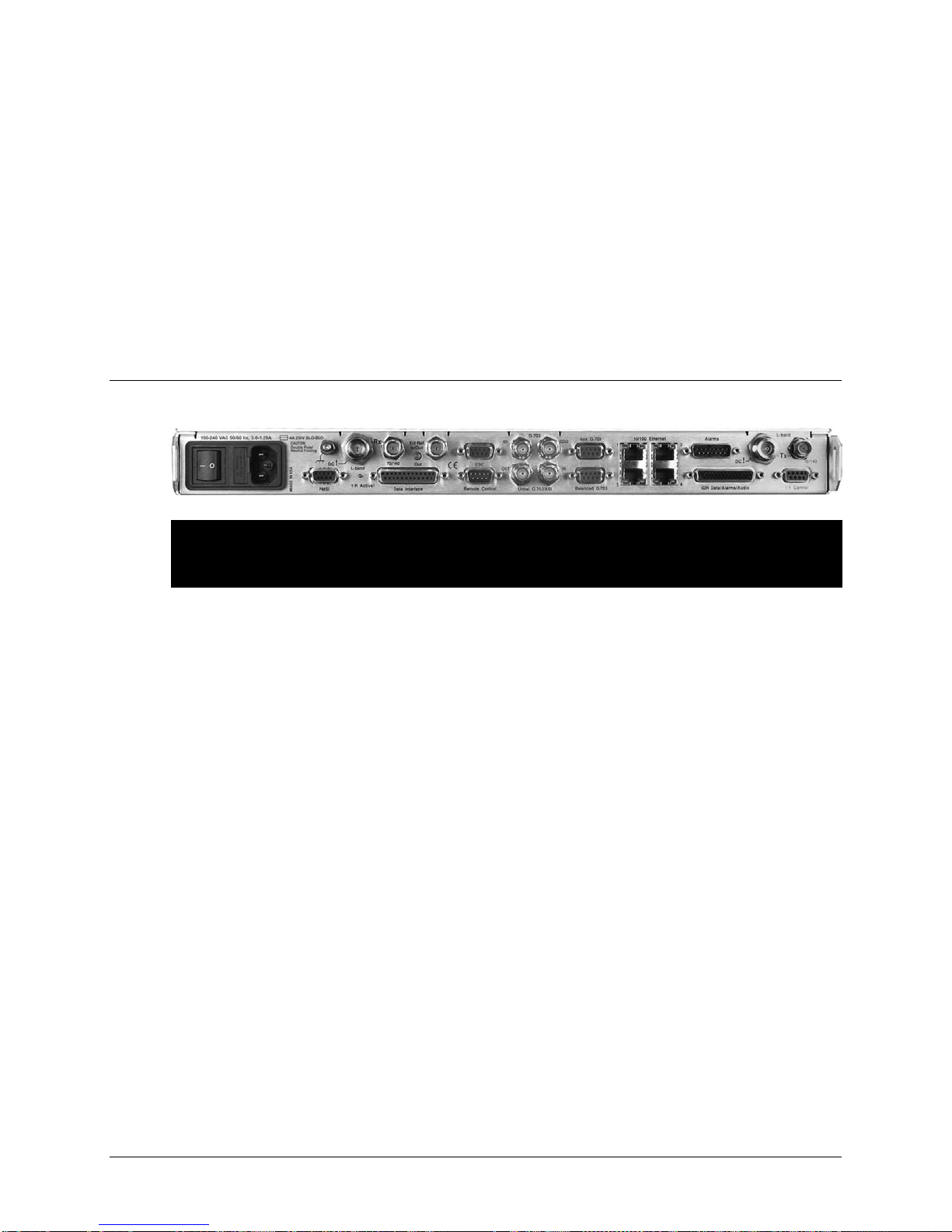
Chapter 3. REAR PANEL
CONNECTORS
3.1 CDM-625 Rear Panel Overview
Figure 3-1. CDM-625 Rear Panel View
(Top) Standard AC Chassis (CEFD P/N PL/12587-1)
(Bottom) Optional 48V DC Chassis (CEFD P/N PL/12587-2)
The CDM-625 Advanced Satellite Modem’s rear panel, shown in Figure 3-1, provides all
necessary external connections between the modem and other equipment:
• Section 3.2 details the cabling connections provided on the rear panel interface,
grouped according to service function. Where applicable, the connector’s pinout table is
provided.
• Section 3.3 details the CDM-625 grounding and power features.
AND PINOUTS
3–1
Page 78
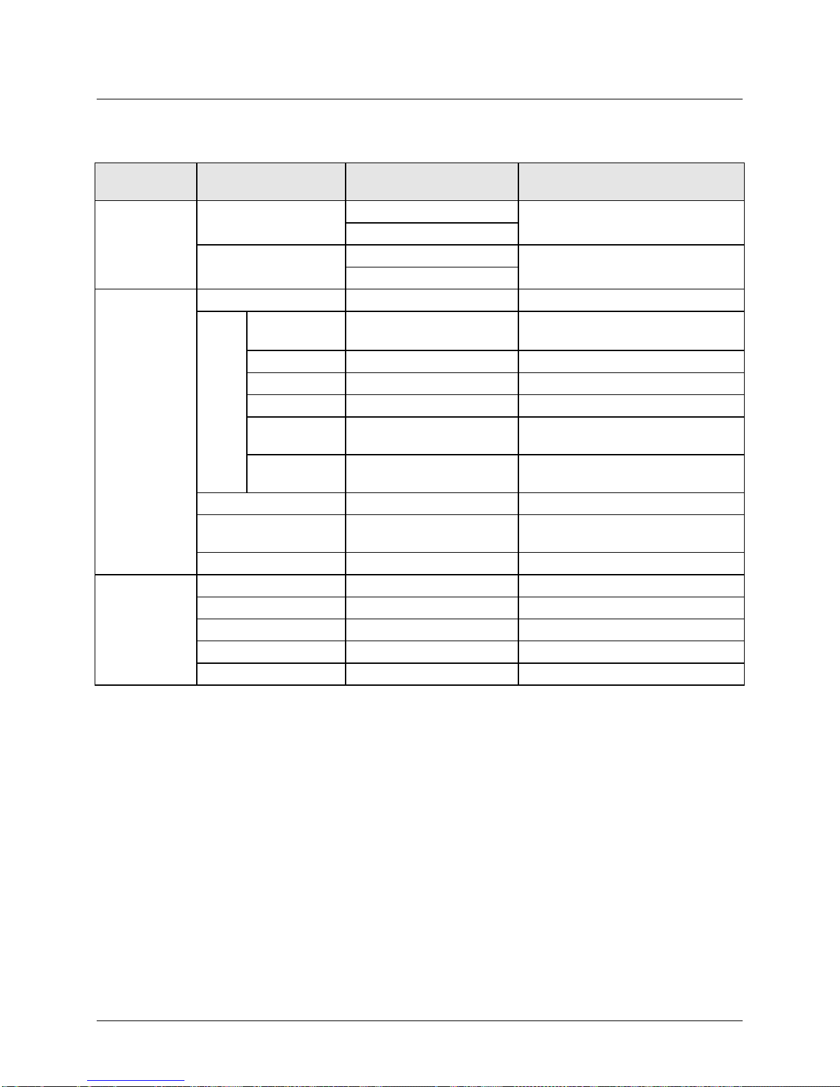
CDM-625 Advanced Satellite Modem Revision 13
Connector
Group (Sect)
IF
BNC female (70/140MHz band)
Type ’N’ female (L-Band)
BNC female (70/140MHz band)
Type ’N’ female (L-Band)
Terrestrial Data
Data Interface
25-pin Type ‘D’ female
Serial synchronous data input/output
G.703, D&I or D&I++;
Quad E1 Ports 1 & 2
Auxiliary G.703
9-pin Type ‘D’ female
Quad E1 Ports 3 & 4
Unbalanced Out
BNC female
Receive G.703 (IDO); ASI
Unbalanced In
BNC female
Transmit G.703 (DDI);ASI
G.703 In
Drop Data Output / Sub-rate Auxiliary Rx
G.703 Out
10/100 Ethernet
(4X) RJ-45 female
10/100 Base-T management and data
44-pin High Density Type ‘D’
ESC
9-pin Type ‘D’ female
ESC Input/output (RS232/485)
Utility
Alarms
15-pin Type ‘D’ male
Form C Alarms (relay closures)
PMSI
9-pin Type ‘D’ female
Pre-Mapped Symbol Interface (CnC)
1:1 Control
9-pin Type ‘D’ female
Connection to External 1:1 Controller
External Reference
BNC female
Input/output
The European EMC Directive 2004/108/EEC (EN 55022, EN 50024) requires using properly
Rear Panel Connectors and Pinouts MN-CDM625
3.2 CDM-625 Cable Connections
Table 3-1. CDM-625 Rear Panel Cabling Connections
Name Connector Type Function
Sect. 3.2.1
Sect. 3.2.2
Sect. 3.2.3
Rx
Tx
Balanced G.703 9-pin Type ‘D’ female
G.703
Data
IDI BNC female
DDO BNC female
IDR Data/Alarms/Audio
Remote Control 9-pin Type ‘D’ male Serial Remote Interface (RS232/485)
female
IF Input
IF Output
Insert Data In / Sub-rate Auxiliary Tx
Intelsat Open Network auxiliary signals
shielded cables for DATA I/O. These cables must be double-shielded from end-to-end,
ensuring a continuous ground shield.
3–2
Page 79
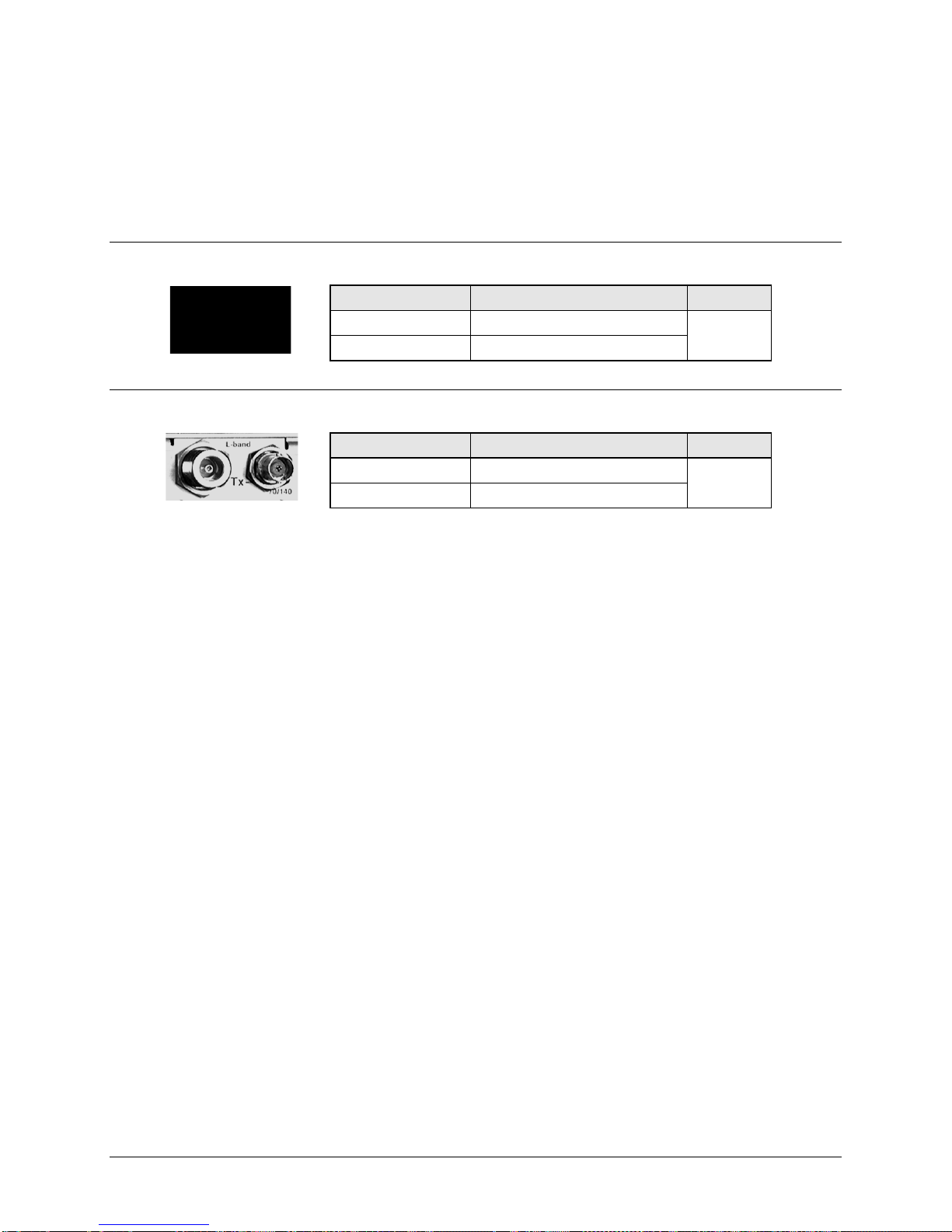
CDM-625 Advanced Satellite Modem Revision 13
Connector Type
Description
Direction
Type ‘N’
Rx IF signal, L- band
BNC
Rx IF signal, 70/140 MHz band
Connector Type
Description
Direction
Type ‘N’
Tx IF signal, L- band
BNC
Tx IF signal, 70/140 MHz band
Rear Panel Connectors and Pinouts MN-CDM625
3.2.1 IF Connection Group
There may be DC voltages present on the Type ‘N’ Rx and Tx IF connectors, up to a
maximum of 48 volts.
3.2.1.1 Rx IF Connectors
In
3.2.1.2 Tx IF Connectors
Out
3–3
Page 80
CDM-625 Advanced Satellite Modem Revision 13
Rear Panel Connectors and Pinouts MN-CDM625
3.2.2 Terrestrial Data Connection Group
3.2.2.1 Data Interface (DB-25F)
The Data Interface connector is a 25-pin, Type ‘D’ female interface that
conducts data input and output signals to and from the modem, and
connects to customer’s terrestrial equipment, breakout panel, or
protection switch.
Table 3-2. Data Interface Connector Pinouts
Pin #
(R-L)
14 Transmit Data B DTE to Modem SD B SD B SD B SD B 103
15 Internal Transmit Clock A Modem to DTE ST A SCT A ST A ST A 114
16 Receive Data B Modem to DTE RD B RD B RD B RD B 104
17 Receive Clock A Modem to DTE RT A SCR A RT A RT A 115
18 (NOTE 2)
19 Request to Send B * DTE to Modem RS B - TA B – 105
20 (NOTE 2)
21 (NOTE 2)
22 Data Set Ready B (NOTE 2) Modem to DTE DM B – – – –
23 (NOTE 2)
24 Transmit Clock A DTE to Modem TT A SCTE A TT A TT A 113
25 (NOTE 2)
Generic Signal Description Direction
1 Shield – Shield FG Shield Shield 101
2 Transmit Data A DTE to Modem SD A SD A SD A SD A 103
3 Receive Data A Modem to DTE RD A RD A RD A RD A 104
4 Request to Send A * DTE to Modem RS A RTS TA A – 105
5 Clear to Send A * Modem to DTE CS A CTS – – 106
6 Data Set Ready A (NOTE 2) Modem to DTE DM A DSR – – –
7 Signal Ground – SG SG SG SG 102
8 Receiver Ready A Modem to DTE RR A RLSD CA A RR A 109
9 Receive Clock B Modem to DTE RT B SCR B RT B RT B 115
10 Receiver Ready B Modem to DTE RR B – CA B RR B 109
11 Transmit Clock B DTE to Modem TT B SCTE B TT B TT B 113
12 Internal Transmit Clock B Modem to DTE ST B SCT B ST B ST B 114
13 Clear to Send B * Modem to DTE CS B – – – 106
EIA-422
EIA 530
V.35 HSSI LVDS
Circuit
#
Notes:
1. When t he rear-panel LED m arked “1:N A ctive!” i s OFF, all of t he signals shown above are available and f unctional. In
addition, pi ns not s hown are not connected, and therefore no damage will occur i f ot her signals ar e c onnected to the
additional pins.
3–4
Page 81

CDM-625 Advanced Satellite Modem Revision 13
The modem must first be configured for the appropriate HSSI operation, via the
CIC-60 Interface Adapter Module CIC-60 Interface Adapter Module
Rear Panel Connectors and Pinouts MN-CDM625
2. When the rear-panel LED marked “1:N Active!” is ON, the signals shown highlighted are no longer available. Furthermore,
pins 6, 18, 20, 21, 22, 23 and 25 are reserved for use by the 1:N system. DO NOT connect signals to any of these pins in
this mode. Certain pins have DC voltages present that may damage equipment other than a Comtech EF Data redundancy
switch.
3. For X.21 operation, use the EIA-422 pins, but ignore Receive Clock if the Modem is DTE, and ignore Transmit clocks if the
Modem is DCE.
4. For IDR operation using G.703, this primary interface becomes the 8 kbps EIA-422 overhead channel.
3.2.2.1.1 HSSI Operation via the CIC-60 Interface Adapter Module
For HSSI operation (Tx, Rx, or both), the optional CIC-60 Interface Adapter Module (Figure 3-2)
may be purchased from Comtech EF Data to adapt the Data Interface 25-pin Type ‘D’ female
connection to a standard 50-pin Type ‘HD’ HSSI (SCSI-II) female connection.
See Table 3-3 for the pinouts for the HSSI/EIA-613 side of the CIC-60 Adapter Module.
CDM-625 Front Panel, before using this adapter:
SELECT: Configure Mode
(Select HSSI for both Tx Mode / Interface and Rx Mode / Interface)
Chapter 5. FRONT PANEL OPERATION
(Modem Interface Side) (Installed, HSSI Interface Side Shown)
Figure 3-2. CIC-60 Interface Adapter Module (CEFD P/N PL-0000307)
3–5
Page 82

CDM-625 Advanced Satellite Modem Revision 13
Pin #
Circuit
1, 26
Signal Ground
SG
102
Ground
2, 27
Receive Timing
RT
115
From DCE
4, 29
Receive Data
RD
104
From DCE
5, 30
Loopback circuit C
LC
undefined
From DCE
Not used
7, 32
Signal Ground
SG
102
Ground
9, 34
Terminal Timing
TT
113
to DCE
10, 35
Loopback circuit A
LA
143
to DCE
Not used
12, 37
Loopback Circuit B
LB
144
to DCE
Not used
14, 39
Not used
undefined
Not used
15, 40
TX DVALID
undefined
Not used
17, 42
Reserved (to DCE)
Not used
18, 43
Reserved (to DCE)
Not used
20
undefined
Not used
45
undefined
Not used
21
undefined
Not used
46
Reserved (to DTE)
Not used
23, 48
undefined
from DCE
Not used
24, 49
Test Mode
TM
142
from DCE
Not used
Rear Panel Connectors and Pinouts MN-CDM625
Table 3-3. CIC-60 Module – HSSI/EIA-613 Side Connector Pinouts
(+,-)
Signal Function HSSI Signal EIA-613 Circuit
Direction
Comment
3, 28 DCE Available CA 107 From DCE
6, 31 Send Timing ST 114 From DCE
8, 33 DTE Available TA 108/2 to DCE
11, 36 Send Data SD 103 to DCE
13, 38 Signal Ground SG 102 Ground
16, 41 Reserved (to DCE) Not used
19, 44 Signal Ground SG 102 Ground
22, 47 undefined from DCE Not used
25, 50 Signal Ground SG 102 Ground
3–6
Page 83
CDM-625 Advanced Satellite Modem Revision 13
Pin #
(R-L)
Signal Function
Serial G.703
Signal Function
D&I or D&I++
Signal Function
Quad D&I
1
Rx out -
IDO -
Port 2 Rx Out -
6
Rx out +
IDO +
Port 2 Rx Out +
2 IDI -
Port 2 Tx In -
7
3
GND
GND
GND
8
4
DDO -
Port 1 Rx Out -
9 DDI -
Port 1 Tx In -
5
Tx in +
DDI +
Port 1 Tx In +
Pin #
Signal Function
Signal Function
Signal Function
1
–
–
Port 4 Rx out -
6
–
–
Port 4 Rx out +
2
–
–
Port 4 Tx in -
7
–
–
Port 4 Tx in +
3
–
–
8
–
–
Port 3 Rx out -
4
–
–
–
–
5 – –
Port 3 Tx in +
Rear Panel Connectors and Pinouts MN-CDM625
3.2.2.2 G.703 Connectors
3.2.2.2.1 Balanced G.703 (DB-9F)
The Balanced G.703 connector is a 9-pin Type ‘D’ female connector. It is
used for single port G.703, D&I or D&I++. When used with Quad E1
operations, this connector serves Ports 1 and 2 of the Quad E1 interface.
Table 3-4. Balanced G.703 Connector Pinouts
IDI + Port 2 Tx In +
DDO + Port 1 Rx Out +
3.2.2.2.2 Aux G.703 (DB-9F)
The Auxiliary G.703 connector is a 9-pin Type ‘D’ female connector. When
used with Quad E1 operations, this connector serves Ports 3 and 4 of the
Quad E1 interface.
Table 3-5. Auxiliary G.703 Connector Pinouts
(R-L)
9
Serial G.703
D&I or D&I++
Quad D&I
GND
Port 3 Rx out +
Port 3 Tx in -
3–7
Page 84
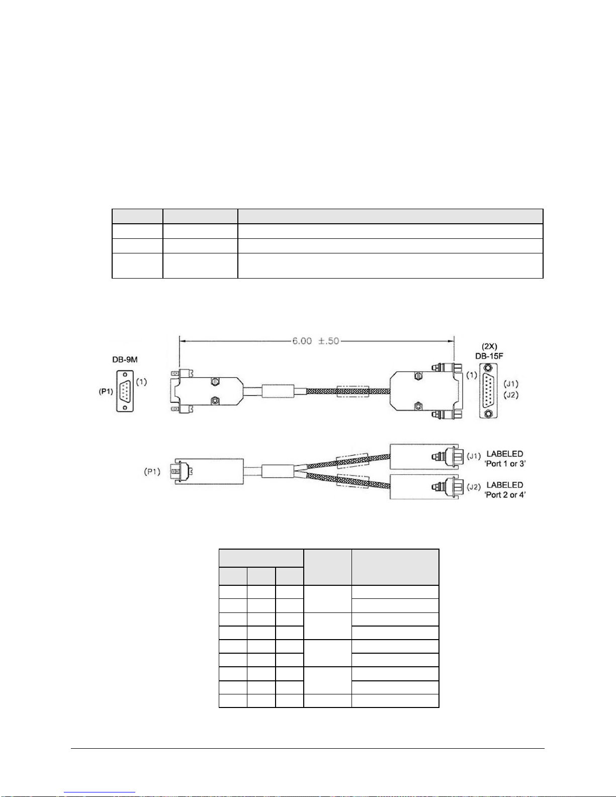
CDM-625 Advanced Satellite Modem Revision 13
provides for two of the four ports of the Quad E1
If all four ports of Quad E1 are needed, the user will need to obtain a
Figure
CEFD Part No.
Converts (1) 9-pin Type ‘D’ Connector (DB-9F) to:
3-3
CA-0000163
(2) DB-15F connections – see Table 3-6 for the connector pinout
3-4
CA-0000164
(2) RJ-48 F connections – see Table 3-7 for the connector pinout
KT-0000122 or
KT-0020570
5 9 X Port 1 or 3 Tx In +
9
1
Port 1 or 3 Tx In -
4
11
Port 1 or 3 Rx In +
8
3
Port 1 or 3 Rx In -
7
9
Port 2 or 4 Tx In +
2
1
Port 2 of 4 Tx In -
6
11
Port 2 or 4 Rx In +
1
3
Port 2 or 4 Rx In -
3
2 2 –
GND
Rear Panel Connectors and Pinouts MN-CDM625
3.2.2.2.3 Quad E1 Operation via the Balanced G.703 / Aux G.703
Connectors
Each adapter cable option
interface.
quantity of (2X) of any adapter option.
For Quad E1 operation, optional Comtech EF Data cabling accessories may be purchased from
Comtech EF Data to adapt the Balanced G.703 or Auxiliary G.703 connectors as follows:
3-5
(2) BNC 75Ω BNC-F connections – see Table 3-8 for the connector pinout
3.2.2.2.3.1 CA-0000163 Adapter Cable
Figure 3-3. CA-0000163 Adapter Cable (DB-9M (2X) DB-15F)
Table 3-6. CA-0000163 Connector Pinouts
P1 J1 J2
Connector
Twisted
3–8
Pair
X
X
X
Signal Function
Page 85

CDM-625 Advanced Satellite Modem Revision 13
5 1 – X Port 1 or 3 Tx In +
9
2
–
Port 1 or 3 Tx In -
4
4
–
Port 1 or 3 Rx In +
8
5
–
Port 1 or 3 Rx In -
7
–
1
Port 2 or 4 Tx In +
2
–
2
Port 2 of 4 Tx In -
6
–
4
Port 2 or 4 Rx In +
1
–
5
Port 2 or 4 Rx In -
3
3 3 –
GND
Rear Panel Connectors and Pinouts MN-CDM625
3.2.2.2.3.2 CA-0000164 Adapter Cable
Figure 3-4. CA-0000164 Adapter Cable (DB-9M (2X) RJ-48F)
Table 3-7. CA-0000164 Connector Pinouts
Connector
P1 J1 J2
Twisted
Pair
X
X
X
Signal Function
3–9
Page 86
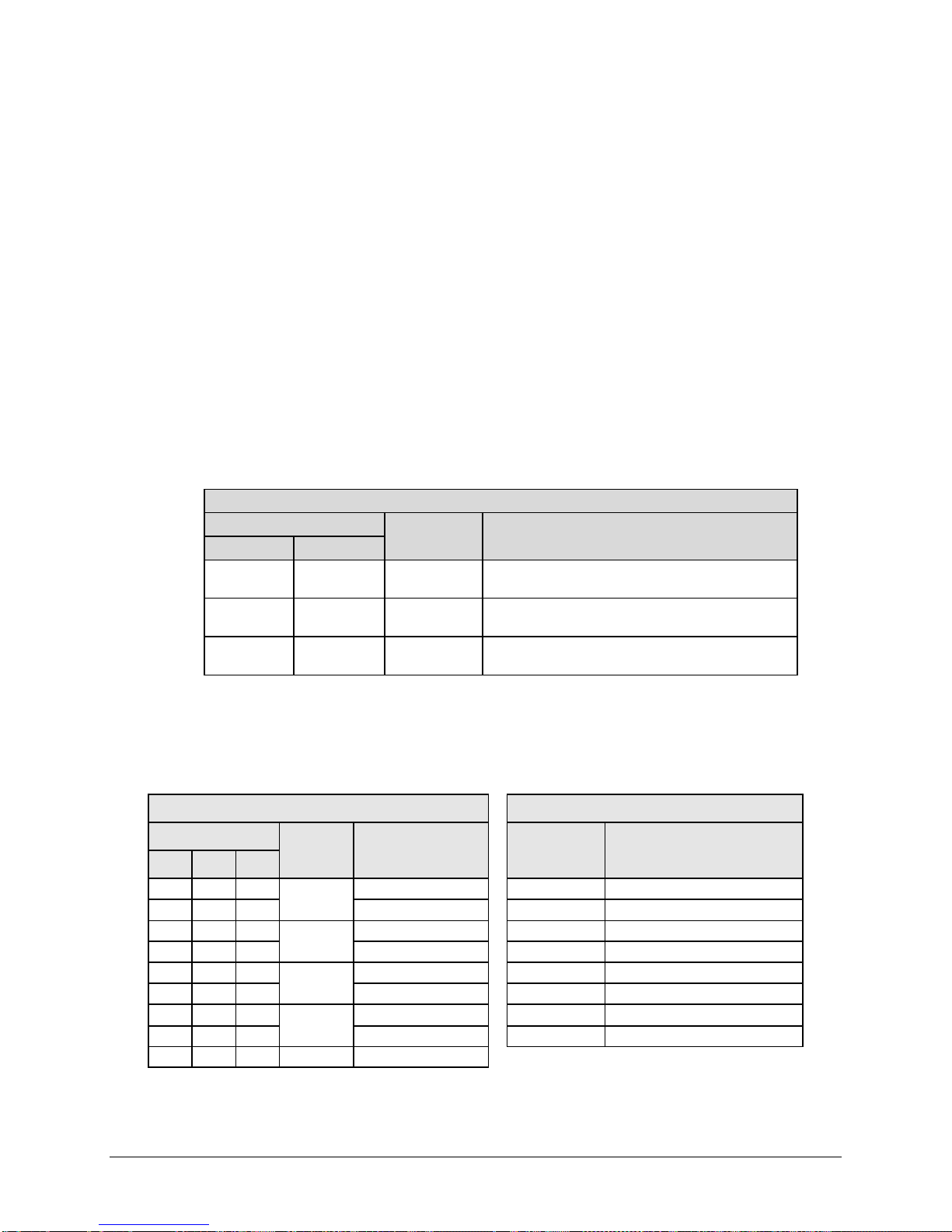
CDM-625 Advanced Satellite Modem Revision 13
Y-Cable Assembly, 6”, DB-9M 2X RJ-48 Male
(See Table 3-8)
Y-Cable Assembly, 3’, DB-9M 2X RJ-48 Male
Female
5 1 – X Port 1 or 3 Tx In +
1
WHITE / ORANGE STRIPE
9
2
–
Port 1 or 3 Tx In -
2
ORANGE
4
4
–
Port 1 or 3 Rx In +
3
WHITE / GREEN STRIPE
8
5
–
Port 1 or 3 Rx In -
4
BLUE
7
–
1
Port 2 or 4 Tx In +
5
WHITE / BLUE STRIPE
2
–
2
Port 2 of 4 Tx In -
6
GREEN
–
4
1
–
5
Port 2 or 4 Rx In -
8
BROWN
3
3 3 –
GND
Rear Panel Connectors and Pinouts MN-CDM625
3.2.2.2.3.3 KT-0000122/KT-0020570 Quad E1 Balanced/Unbalanced Adapter
Cable Kits
Quad E1 Balanced/Unbalanced Adapter Kits
Kit / Quantity
KT-0000122 KT-0020570
Part Number Description
1 – CA-0000347
– 1 CA-0020710
2 2 502-0532-001
Figure 3-5. Quad E1 Balanced/Unbalanced Adapter Cable Kits
Connector
P1 J1 J2
6
(See Table 3-8)
Bolun Adapter, 2X RJ-48 Female 2X BNC 75Ω
Table 3-8. CA-0000347/CA-0020710 Connector Pinouts
P1 PINOUT
Twisted
Pair
X
X
X
Signal Function PIN WIRE COLOR
Port 2 or 4 Rx In + 7 WHITE / BROWN STRIPE
J1/ J2 TYPICAL WIRE CHART
3–10
Page 87
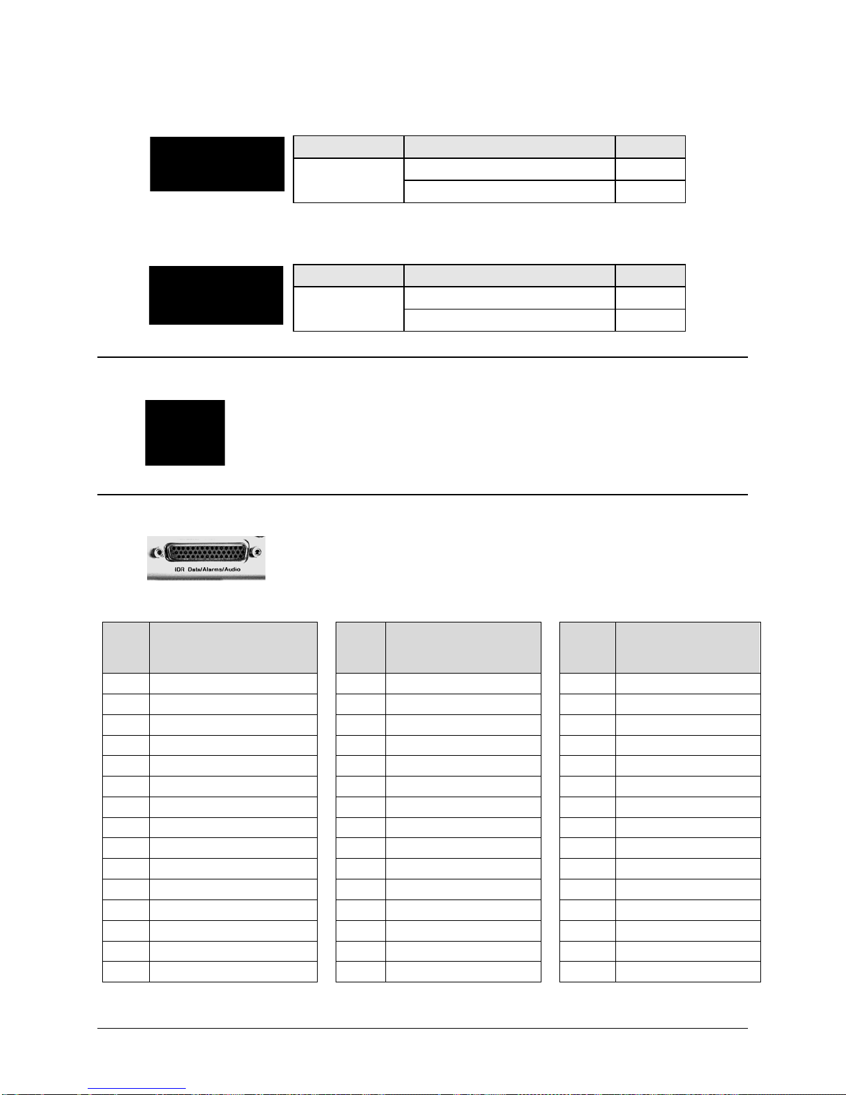
CDM-625 Advanced Satellite Modem Revision 13
Connector Type
Description
Direction
G.703 Unbalanced Rx (IDO) / ASI
Out
G.703 Unbalanced Tx (DDI) / ASI
In
Connector Type
Description
Direction
IDI (Insert Data Input)
In
DDO (Drop Data Output)
Out
Rear Panel Connectors and Pinouts MN-CDM625
3.2.2.2.4 Unbal G.703 / ASI – Out (IDO), In (DDI)
BNC
3.2.2.2.5 G.703 IDI (Insert Data In), DDO (Drop Data Out)
BNC
3.2.2.3 Quad 10/100 Ethernet (RJ-45)
These are four standard RJ-45 female connectors, operating at 10/100 Mbps, half
and full duplex, auto-negotiating.
\
3.2.2.4 IDR Data / Alarms / Audio (HD-44F)
The IDR Data/Alarms/Audio interface is a 44-pin, high-density Type ‘D’
female connector.
Table 3-9. IDR Data/Alarms/Audio Connector Pinouts
Top
Pin #
(R-L)
1 BWA4 out Normally Closed 16 No Connect 31
2 BWA3 out Normally Closed 17
3 BWA2 out Normally Closed 18
4 BWA1 out Normally Closed 19
5 No Connect 20
6 RS-422 Tx ESC Data A in 21 TBD RS-422 B in 36 RS-422 Tx ESC Data B in
7 RS-422 Tx Octet B out 22 RS-422 Tx Octet A out 37
8 BWA3 in 23
9 Audio Out 2- 24
10
11
12 RS-422 Tx ESC Clock A out 27 RS-422 Tx ESC Clock B out 42 TBD RS-422 A out
13
14
15 Ground 30
Description
Audio In 2+
Audio In 1-
RS-422 Rx Octet A out
RS-422 Rx ESC Clock B out
Center
Pin #
(R-L)
25
26
28 TBD RS-422 B out 43
29
Description
BWA4 out Common
BWA3 out Common
BWA2 out Common
BWA1 out Common
BWA4 in
BWA1 in
Audio In 2-
Audio Out 1+
RS-422 Rx ESC Clock A out
RS-422 Rx ESC Data B out
Bottom
Pin #
(R-L)
32
33
34
35 TBD RS-422 A in
38 BWA2 in
39 Audio Out 2+
40
41
44
Description
BWA4 out Normally Open
BWA3 out Normally Open
BWA2 out Normally Open
BWA1 out Normally Open
Audio Out 1-
Audio In 1+
RS-422 Rx Octet B out
RS-422 Rx ESC Data A out
3–11
Page 88
CDM-625 Advanced Satellite Modem Revision 13
Pin #
(R-L)
2
RS-232 Rx Data out
RS-232 Rx Data out
7
RS-485 Tx Data A in
–
8
RS-485 Rx Data B out
–
4 – RS-232 Rx Clock out
9
RS-485 Rx Data A out
–
Pin #
(L-R)
1
Ground
–
6
EIA-485 Receive Data ‘B’ *
In
2
EIA-232 Transmit Data
Out
7
EIA-485 Receive Data ‘A’ *
In
3
EIA-232 Receive Data
In
8
EIA-485 Transmit Data ‘B’ *
Out
4
Reserved – Do Not Use
–
9
EIA-485 Transmit Data ‘A’ *
Out 5 Ground
–
Rear Panel Connectors and Pinouts MN-CDM625
3.2.2.5 ESC (DB-9F)
The ESC (Engineering Service Channel) port is a 9-pin Type ‘D’ female
connector.
Table 3-10. ESC Connector Pinouts
Asynchronous Synchronous
1 Ground Ground
6 RS-485 Tx Data B in –
3 RS-232 Tx Data in RS-232 Tx Data in
5 – RS-232 Tx Clock out
3.2.3 Utility Connections Group
3.2.3.1 Remote Control (DB-9M)
The Remote Control interface is a 9-pin Type ‘D’ male connector. It is
intended for connection to an M&C computer or terminal device, and is user
selectable for either EIA-232 or EIA-485.
Table 3-11. Remote Control Connector Pinouts
Description Direction
*Use for EIA-485 2-wire operation
3–12
Page 89
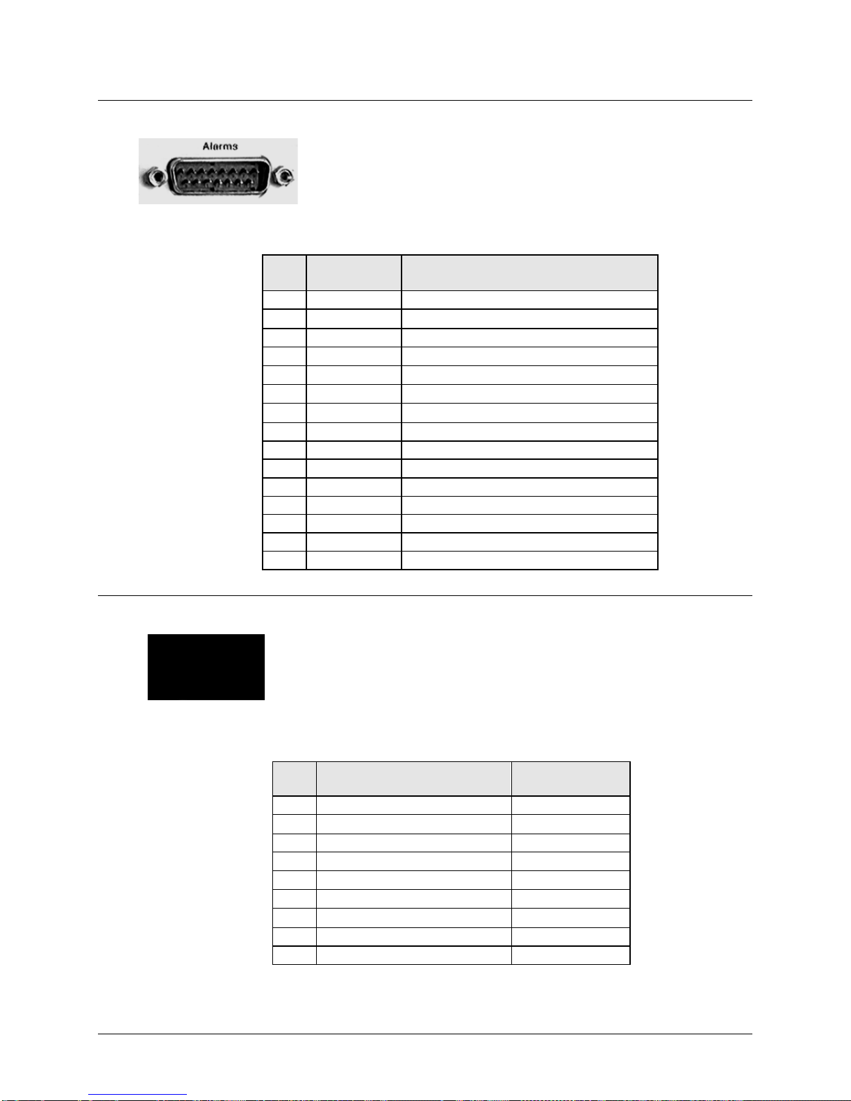
CDM-625 Advanced Satellite Modem Revision 13
Pin #
(L-R)
2
AGC
AGC Voltage (Rx signal level, 0 to 10 Volts)
10
N/A
Spare (No connection)
11
RX-I
RX I Channel (Constellation Monitor)
4
UNIT-COM
Unit Fault
12
UNIT-NO
Unit Fault (Energized, No Fault)
13
TX-COM
Tx Traffic
6
TX-NO
Tx Traffic (Energized, No Fault)
14
TX-NC
Tx Traffic (De-energized, No Fault)
7
RX-COM
Rx Traffic
15
RX-NO
Rx Traffic (Energized, No Fault)
8
RX-NC
Rx Traffic (De-energized, No Fault)
Pin #
(R-L)
1
Ground
–
6
Spare (No connection)
–
2
Spare (No connection)
–
7
PMSI symbol clock – RS485 -
In/Out
3
PMSI symbol clock – RS485 +
In/Out
8
PMSI LSB – RS485 -
In/Out
4
PMSI LSB – RS485 +
In/Out
9
PMSI MSB – RS485 -
In/Out
5
PMSI MSB – RS485 +
In/Out
Rear Panel Connectors and Pinouts MN-CDM625
3.2.3.2 Alarms (DB-15M)
Unit alarms are provided on this 15-pin Type ‘D’ male connector.
Table 3-12. Alarm Interface Connector Pinouts
Name Signal Function
1 GND Ground
9 EXT-OFF EXT Carrier OFF
3 RX-Q Rx Q Channel (Constellation Monitor)
5 UNIT-NC Unit Fault (De-energized, No Fault)
3.2.3.3 PMSI Connector, DB-9F
The PMSI (Pre-Mapped Symbol interface) is a 9-pin Type ‘D’ female
connector. The PMSI is an EIA-485 multidrop bus system, used in tandem
with Carrier-in-Carrier (CnC), where one device transmits, and all other
devices on the multidrop bus are configured to receive.
Table 3-13. PMSI (Pre-Mapped Symbol Interface) Connector Pinouts
Description Direction
3–13
Page 90
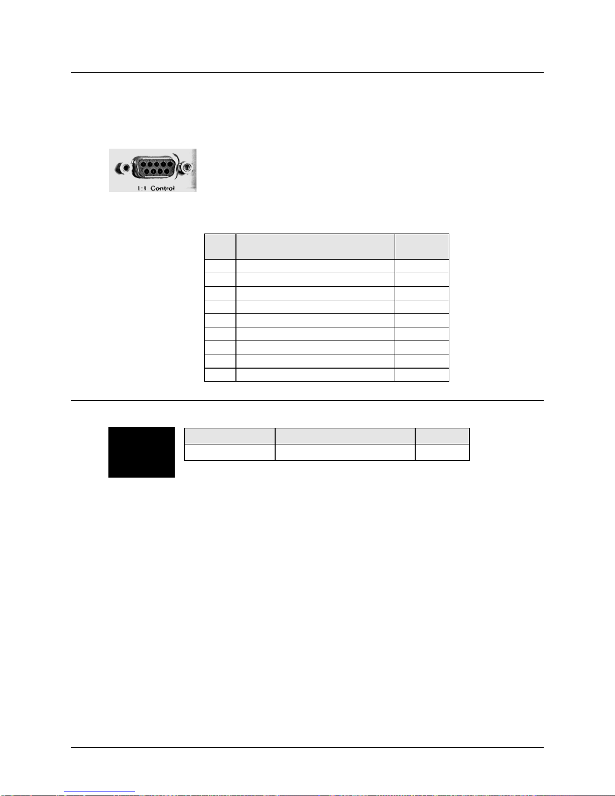
CDM-625 Advanced Satellite Modem Revision 13
Pin #
6
Transmit Serial Data – auxiliary channel
Out
2
Receive Serial Data – auxiliary channel
In
7
Redundancy Out 1
Out
Redundancy In 1
8
Redundancy Out 2
Out
4
Redundancy In 2
In
9
Fused +12 volt Out
Out
Connector Type
Description
Direction
BNC
External Reference
In/Out
Rear Panel Connectors and Pinouts MN-CDM625
3.2.3.4 1:1 Control (DB-9F)
The 1:1 Control connector is intended only for connection to a CRS-170A or CRS-180
Redundancy Switch.
The 1:1 Control connector is a 9-pin Type ‘D’ female connector.
Table 3-14. 1:1 Control Interface Connector Pinouts
3.2.3.5 Ext Ref In/Out
(R-L)
Description Direction
1 Ground –
3
5 Ground –
In
3–14
Page 91

CDM-625 Advanced Satellite Modem Revision 13
to the protective earth connection at all times. It is therefore imperative that the unit
Rear Panel Connectors and Pinouts MN-CDM625
3.3 CDM-625 Ground and Power Connections
3.3.1 Chassis Ground Interface
PROPER GROUNDING PROTECTION IS REQUIRED. The equipment must be connected
is properly grounded, using the ground stud provided on the unit rear panel, during
installation, configuration, and operation.
Figure 3-6. CDM-625 Chassis Ground Interface
(Top) Standard AC C has sis (CEFD P/N PL /12587-1)
(B ottom) Optional 48V DC C has s is (CE F D P/N PL /12587-2)
Use the #10-32 stud, located adjacent to the power interface, for connecting a
common chassis ground among equipment.
The AC power interface provides the safety ground.
3–15
Page 92
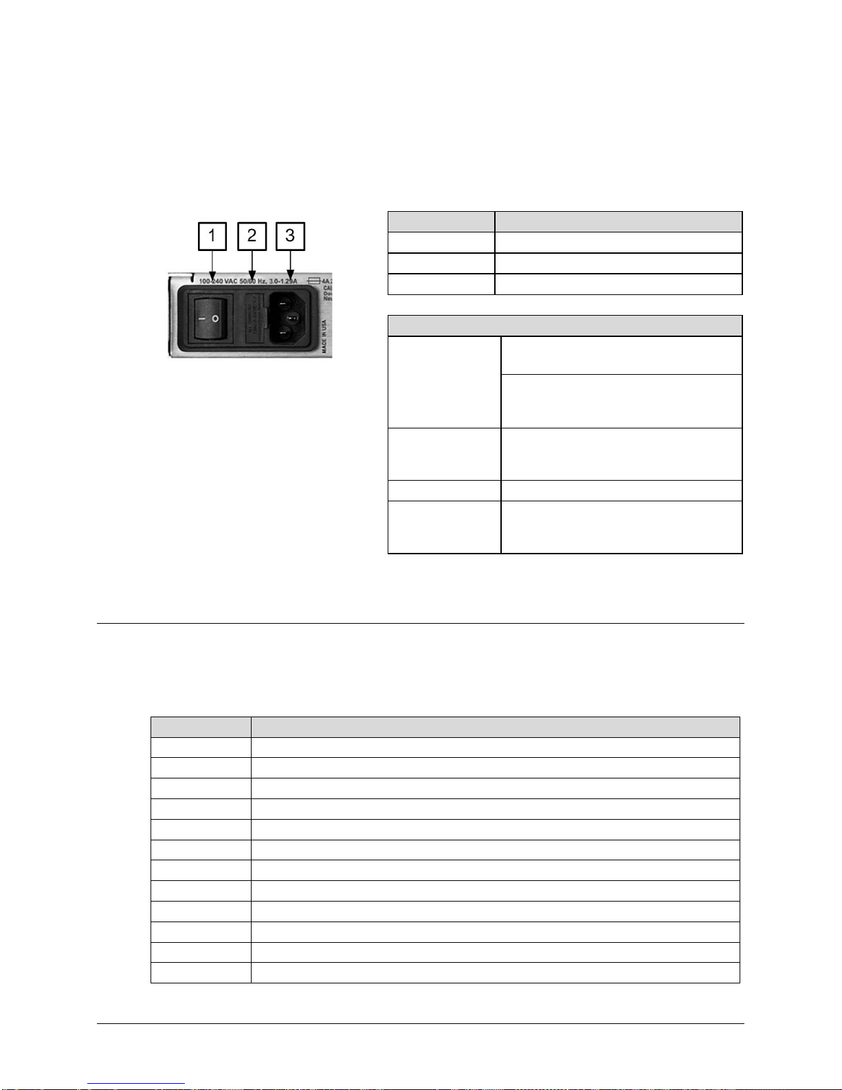
CDM-625 Advanced Satellite Modem Revision 13
Feature
Description
1
On / Off Switch
2
Press-fit Fuse Holder
3
IEC-60320 Type C14 Three-prong Connector
AC Power Specifications
48 watts (typical with TPC/LDPC Codec and
CnC module installed), 68 watts (max)
300 watts (max)
100V to 240V AC, +6%/-10%, autosensing
AC)
Connection Type
IEC-60320 Type C13/C14
Line and neutral fusing
T4A ( 250V AC operation)
CEFD P/N
Description
KT-0000226
AC to 48V DC Conversion Kit
KT-0000283
AC Primary Power Supply: 100-240 VAC (65W Power Supply) w/required cables
KT-0020701
AC Primary Power Supply: 100-240 VAC (175W Power Supply) w/required cables
PP-0020556
AC Power Cord – India
Rear Panel Connectors and Pinouts MN-CDM625
3.3.2 Standard 100V/240V Alternating Current (AC) Power Interface
Input Power
Input Voltage
Fuse Protection
Figure 3-7. CDM-625 Standard AC Chassis (CEFD P/N PL/12587-1)
3.3.2.1 AC Operation – CDM-625 Accessories
Contact your Comtech EF Data sales representative during normal business hours to purchase
any of these available accessories:
KT-0020703 AC to 24V DC Conversion Kit
280 watts (typical TPC/LDPC Codec, CnC
module and 48 volt BUC supply installed),
(total absolute max. range is 90V to 264V
(2X) 5mm x 20mm Slow-blow type fuses:
PS-0000075 AC 65W Power Supply
PS-0000065 AC 175W Power Supply
CA/17725 AC Power Cord, Standard (IEC-60320 Type C13) – USA
CA/90025-5FT AC Power Jumper Cord, Standard (IEC-60320 Type C13)
KT/11633-1 AC Power Cord Retainer Kit (for any AC Cord)
CA/17850 AC Power Cord – European / French
PP-0000097 AC Power Cord – Japanese
3–16
Page 93

CDM-625 Advanced Satellite Modem Revision 13
Rear Panel Connectors and Pinouts MN-CDM625
3.3.2.2 AC Operation – Applying Power
Figure 3-8. Applying AC Power to the CDM-625
To apply AC power to the CDM-625 (Figure 3-8):
• First, plug the provided AC power cord female end into the unit.
• Then, plug the AC power cord male end into the user-supplied power source.
• Finally, switch the unit ON.
3.3.2.3 AC Operation – Replacing Fuses
For AC operation the CDM-625 uses two common 5mm x 20mm Slow-blow fuses – one each for
line and neutral connections. The fuses are contained within a fuse holder that is press-fit into
the body of the IEC power module (located on the rear panel, Figure 3-9).
Figure 3-9. Replacing CDM-625 AC Fuses
To replace the fuse(s):
DISCONNECT THE POWER SUPPLY BEFORE PROCEEDING!
• First, unseat the fuse holder from the IEC power module.
3–17
Page 94
CDM-625 Advanced Satellite Modem Revision 13
Feature
Description
1
On / Off Switch
2
Power Terminal Block
3
Screw-in Fuse Holders / Receptacles
DC Power Specifications
48 watts (typical with TPC/LDPC Codec and CnC
module installed), 68 watts (max)
280 watts (typical TPC/LDPC Codec, CnC module
and 48 volt BUC supply installed), 300 watts (max)
43 – 60 VDC Nominal
Connector Type
Terminal Block
(2X) 5mm x 20mm Slow-blow type fuses:
BUC Fuse: 6.3 Amp/250 Volts
Rear Panel Connectors and Pinouts MN-CDM625
o Use the slot to pry the holder outward from the IEC power module.
o Pull the holder straight out, and then swing the holder away from the module.
• Then, remove and replace the T4A (4 Amp) fuses as needed.
FOR CONTINUED OPERATOR SAFETY, ALWAYS REPLACE THE FUSES WITH THE
CORRECT TYPE AND RATING.
• Finally, reseat the fuse holder in the IEC power module.
3.3.3 Optional 48V Direct Current (DC) Power Interface
This DC input design supersedes the configuration featured on modems built prior
to May 2009.
Input Power
Input Voltage
36 – 60 VDC Maximum
Fuse Protection
Modem Fuse: 3Amp/250Volts
Figure 3-10. CDM-625 Optional DC Chassis (CEFD P/N PL/12587-2)
3–18
Page 95

CDM-625 Advanced Satellite Modem Revision 13
KT-0000282
DC Primary Power Supply: -48 VDC, w/required cables
PS-0000066
DC 48V 125W Power Supply
PS-0020545
DC 24V 120W Power Supply
Rear Panel Connectors and Pinouts MN-CDM625
3.3.3.1 Optional DC Operation – CDM-625 Accessories
Contact your Comtech EF Data sales representative during normal business hours to purchase
any of these available accessories:
CEFD P/N Description
KT-0020683 DC to AC Conversion Kit for CDM-625 Base Modem
KT-0020680 DC to AC Conversion Kit for CDM-625 with IP Packet Processor
CA-0000455 DC Pigtail Adapter
KT/9640-3 BUC Power Supply: 24 VDC 90W (50° C) (100-240 VAC Input)
KT-0000029 BUC Power Supply: 48 VDC 150W (50° C) (100-240 VAC Input)
KT-0000185 BUC Power Supply: 24 VDC 90W (50° C) (-48 VDC Input)
KT-0000186 BUC Power Supply: 48 VDC 150W (50° C) (-48 VDC Input)
3.3.3.2 Optional DC Operation – Applying Power
Figure 3-11. Applying Power to the CDM-625 Optional DC Chassis
To apply DC power to the CDM-625:
• First, connect the user-supplied (+) and (–) DC power leads to their respective terminals.
Number 18 AWG minimum wires are recommended.
• Then, connect the user-supplied DC power leads to the power source.
• Finally, switch the unit ON.
3–19
Page 96

CDM-625 Advanced Satellite Modem Revision 13
FOR CONTINUED OPERATOR SAFETY, ALWAYS REPLACE THE FUSES WITH
Rear Panel Connectors and Pinouts MN-CDM625
3.3.3.3 Optional DC Operation – Replacing Fuses
For DC operation the CDM-625 requires two different fuses that are contained within the
individual screw-in receptacles below the terminal block (located on the rear panel, Figure
3-12).
Figure 3-12. Replacing CDM-625 Optional DC Chassis Fuses
To replace the fuses:
DISCONNECT THE POWER SUPPLY BEFORE PROCEEDING!
• First, unscrew either fuse holder from its receptacle. Then, remove and replace the modem
and/or the BUC fuse(s):
o Use T3A (3 Amp) 250V fuses for modem operation (left-hand receptacle).
o Use T6.3A (6.3 Amp) 250V fuses when a Block Upconverter (BUC) is installed (right-hand
receptacle).
THE CORRECT TYPE AND RATING.
• Screw either fuse holder back into its receptacle.
3–20
Page 97
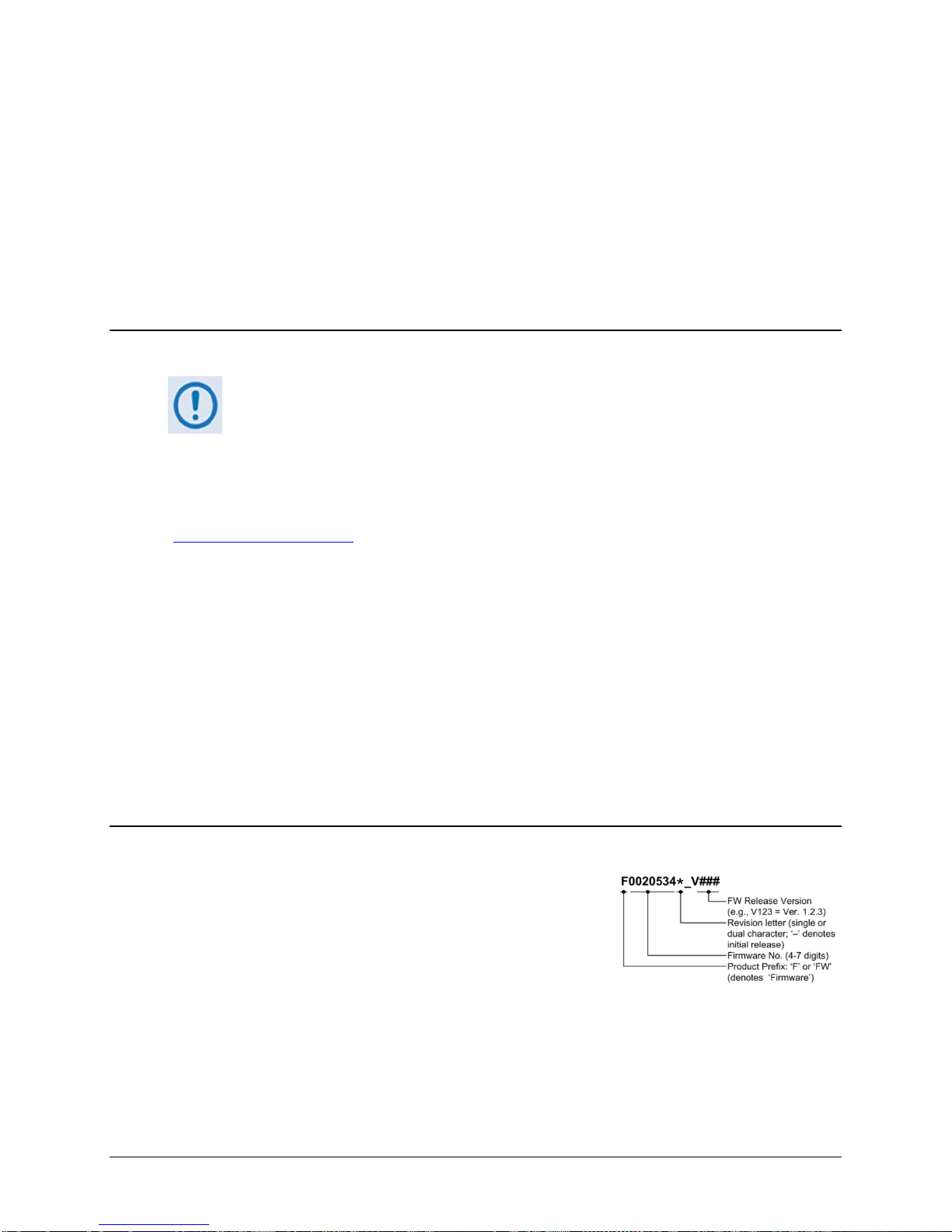
Chapter 4. UPDATING FIRMWARE
4.1 Updating Firmware via Internet
TO ENSURE OPTIMAL PERFORMANCE, IT IS IMPORTANT TO OPERATE THE CDM-625
WITH ITS LATEST AVAILABLE FIRMWARE.
The CDM-625 Advanced Satellite Modem is factory-shipped with its latest version of operating
firmware. If a firmware update is needed, once Ethernet connectivity has been established with
the unit, the update can be downloaded from the Comtech EF Data Web site
www.comtechefdata.com), or obtained through Comtech EF Data Customer Support via e-mail
(
or on CD by standard mail delivery.
The CDM-625 Firmware Update process is as follows:
• Perform the update without opening the CDM-625 by connecting the rear panel serial
“Remote Control” port or “10/100 Ethernet” port to a serial or 10/100 BaseT Ethernet port
of the user PC.
• Download the firmware update via the Internet to the user PC.
• Transfer the firmware update, via File Transfer Protocol (FTP), from the user PC to the
CDM-625.
4.2 About Firmware Files, Naming, Versions, and Archive Formats
Comtech EF Data’s Web site catalogues its firmware update
files by product type (e.g., modem, converter, etc.) and
specific model/optional configuration. The hyperlinks appear
as per the example to the right. This example depicts the
F0020534*_V### base modem bulk firmware download
hyperlink (where ‘###’ indicates the firmware version
number, and ‘*’ denotes the revision letter of that version).
In addition to this base modem bulk firmware archive file, downloads are available for the
CDM-625’s optional IP Packet Processor Module, available with or without AES Encryption. This
module requires separate firmware update.
4–1
Page 98
CDM-625 Advanced Satellite Modem Revision 13
Web Hyperlink
EXE/ZIP Filename
Contains Image File ( where ‘ * ’ denotes revision letter)
Fw12864*.bin
Base modem firmware up to FW Version 1.6.0
Fw-0020534*.bin
Base modem firmware from FW Version 2.0.1 to current
FW-0000342*.bin
IP Packet Processor Module op tion without AES Encryption.
FW-0000438*.bin
IP Packet Processor Module op tion with AES E ncryption.
Only firmware for the CDM-625 base modem and IP Packet Processor Module
For additional help with "zipped" file types, refer to the help files provided with the
Updating Firmware MN-CDM625
Firmware updates are available from Comtech EF Data per the following table:
F12864*_V### FW12864*
F0020534*_V### Fw-0020534*
F0000342*_V### FW0000342*
CONTACT CEFD FW0000438*
without AES Encryption is available for download from the CEFD Web site. To
obtain the firmware update for the CDM-625 IP Packet Processor Module with
AES Encryption, contact Network Product Customer Support:
Phone: 480.333.2433
E-mail: [email protected].
The firmware download files are available from Comtech EF Data in two archive file formats:
*.exe (self extracting) and *.zip (compressed). Some firewalls will not allow the downloading of
*.exe files; in this case, download the *.zip file instead. If applicable, one version prior to the
current release is also available for download.
"PKZIP for Windows", "WinZip", or "ZipCentral" file archiving programs. “PKZIP for
Command-line” is not supported due to file naming conventions.
To verify the correct firmware number, see Step 2 in Sect. 4.3.1 Getting Started: Preparing for
the Firmware Download.
4–2
Page 99

CDM-625 Advanced Satellite Modem Revision 13
1
Connect the Windows-based user PC to the CDM-625:
2
Identify the CDM-625 configuration in use, and its firmware number and current version:
Updating Firmware MN-CDM625
4.3 Firmware U pdate Procedure
4.3.1 Getting Started: Preparing for the Firmware Download
Step Task
• Connect the appropriate modem Ethernet port either via a hub or a switch or directly with an Ethernet or
crossover cable. Make sure that a compatible web browser is running on the PC.
• Connect the modem “Remote Control” port to a serial port on the PC. Make sure that a terminal emulator
program such as Hyper Terminal is running on the PC.
A. For the CDM-625 Base Modem, the firmware number and running version can be obtained as follows:
• From the modem front panel – The firmware version is available from the VFD’s top-level “splash” screen. To
view this screen, press the [CLEAR] key several times.
The firmware numbers are provided within the SELECT: UTIL Firmware Info Image#1 or
B. For the CDM-625 with installed IP Packet Processor, the firmware number and running version can be
Image#2 menu screens. For more information, see Chapter 5. FRONT PANEL OPERATION.
• From HTTP via the Base Modem Web Server Interface – The Bootrom, Bulk1 and Bulk2 firmware loads may
be viewed on the Admin | Firmware | Base Modem page. For more information, see Chapter 6.5. Web
Server (HTTP) Interface.
• Using serial Remote Control query – The firmware number, versions, and revision level can be queried as
follows:
Abbreviated: <0/SWR> or:
Detailed: <0/FRW?x (where: x = B (Boot), 1 (Image 1) or 2 (Image 2))
For more information, see Appendix D. SERIAL REMOTE CONTROL.
obtained as follows:
• From the modem front panel – Select the Utilities: Firmware Packet-Processor Info Image#1 or
Image#2 menu trees. For more information, see Chapter 5. FRONT PANEL OPERATION.
• From HTTP via the Base Modem Web Server Interface – Select the Admin | Firmware | Packet Processor
page. The Bootrom, Bulk1 and Bulk2 firmware l oads may be viewed here. For more inf ormation, s ee Chapte r 6.5
Web Server (HTTP) Interface.
• Using serial Remote Control query – Use the IP Packet Processor’s firmware revision query <0/VS1? (Image
1) or <0/VS2? (Image 2).
For more information, see Appendix D. REMOTE CONTROL.
4–3
Page 100

CDM-625 Advanced Satellite Modem Revision 13
3
Create a temporary folder (subdirectory) on the user PC for the firmware archive file download.
Drive letter “c:” is used in these examples. Any valid, writable drive letter can be used.
A temporary folder may be created on a Windows-based PC using differing methods:
unused name.
Updating Firmware MN-CDM625
Step Task
•
• Typical for all tasks: Type the command without quotes, and then press Enter to execute.
A. Use the Windows Desktop to create and rename the temporary folder.
• Right-click anywhere on the desktop to open the popup submenu, and then select New > Folder to create the
temporary folder. The “New Folder” will be created on the desktop.
• Right-click on th e “New Folder” and then select ‘Rename’ from the popup submenu. Rename this folder to
"temp" or some other convenient, unused name.
B. Use Windows Command-line to create the temporary folder.
• First, click [Start] on the Windows taskbar, and then click the Run... icon (or, depending on Windows OS
versions prior to Windows 95, click the MS-Command-line Prompt icon from the Main Menu).
• Next, open a Command-line window…
o For Windows 95 or Windows 98, type “command”.
o For any Windows OS versions later than Windows 98, type “cmd” or “command”.
o Alternately, from [Start], select All Programs > Accessories > Command Prompt.
• Finally, from the Command-line prompt (c:\>), type “mkdir temp” or “md temp” (mkdir and md stand for
make directory), and then click [OK].
C. Use the ‘Run’ and ‘Browse’ windows to create and rename the temporary folder.
• Select [Start] on the Windows taskbar, and then click the Run... icon. The ‘Run’ window will open.
• Click [Browse] in the ‘Run’ window. The ’Browse’ window will open.
• Click the Create New Folder icon in the ‘Browse’ window. The “New Folder” will be created.
• Right-click the “New Folder ” folder name, and then rename this folder to “temp” or some other convenient,
There should now be a "temp" folder created and available for placement of the firmware archive file
download.
4–4
 Loading...