

Compaq 226593-B21 - Smart Array 5i RAID Controller, DL360 - ProLiant - Photon, Smart Array 5i Plus User Manual
Page 1

Compaq Smart Array 5i Plus
Controller and Battery Backed Write
Cache Enabler
User Guide
Part Number 266328-001
March 2002 (First Edition)
Page 2

© 2002 Compaq Information Technologies Group, L.P.
Compaq, the Compaq logo, Compaq Insight Manager, ProLiant, ROMPaq, SmartStart, and
SoftPaq are trademarks of Compaq Information Technologies Group, L.P. in the U.S. and/or
other countries. Microsoft, MS-DOS, Windows, and Windows NT are trademarks of
Microsoft Corporation in the U.S. and/or other countries.
All other product names mentioned herein may be trademarks of their respective companies.
Compaq shall not be liable for technical or editorial errors or omissions contained herein. The
information in this document is provided “as is” without warranty of any kind and is subject to
change without notice. The warranties for Compaq products are set forth in the express limited
warranty statements accompanying such products. Nothing herein should be construed as
constituting an additional warranty.
Compaq Smart Array 5i Plus Controller and Battery Backed Write Cache Enabler
March 2002 (First Edition)
Part Number 266328-001
Page 3

Contents
About This Guide
Important Safety Information ...........................................................................................vii
Symbols on Equipment..................................................................................................... vii
Symbols in Text............................................................................................................... viii
Text Conventions............................................................................................................... ix
Related Documents............................................................................................................ ix
Getting Help........................................................................................................................ x
Compaq Technical Support.......................................................................................... x
Compaq Website .......................................................................................................... x
Compaq Authorized Reseller ....................................................................................... x
Reader’s Comments........................................................................................................... xi
Chapter 1
Features
Overview of Controller Features .....................................................................................1-1
Battery Backed Write Cache Enabler........................................................................ 1-2
Memory..................................................................................................................... 1-4
Controller Interface ...................................................................................................1-5
SCSI Support............................................................................................................. 1-5
Drive Array Technology ...........................................................................................1-5
Fault Management Features.............................................................................................1-6
Compaq Smart Array 5i Plus Controller and Battery Backed Write Cache Enabler iii
Page 4

Contents
Chapter 2
Installation Overview
Chapter 3
Installing the Smart Array 5i Plus Controller and Battery Backed
Write Cache Enabler
Chapter 4
Updating the System Firmware
Running System ROMPaq from the CD......................................................................... 4-2
Running System ROMPaq from Diskette....................................................................... 4-2
Creating a System ROMPaq Diskette from the CD ................................................. 4-2
Creating a System ROMPaq Diskette from the SoftPaq File................................... 4-2
Using the Diskette .................................................................................................... 4-3
Chapter 5
Updating the Controller Firmware
Running Options ROMPaq from the Smart Array Controller Support Software CD..... 5-2
Running Options ROMPaq from Diskettes..................................................................... 5-3
Creating Diskettes Using the Smart Array Controller Support Software CD .......... 5-3
Creating Diskettes Using the SmartStart and Support Software CD........................ 5-3
Creating Diskettes Using the SoftPaq File ............................................................... 5-4
Using the Diskettes................................................................................................... 5-4
Updating the System Partition ........................................................................................ 5-5
Chapter 6
Configuring the System
Using RBSU.................................................................................................................... 6-1
Using ORCA ................................................................................................................... 6-3
Chapter 7
Configuring an Array
Using ORCA ................................................................................................................... 7-3
Using ACU...................................................................................................................... 7-5
Running ACU from CD............................................................................................ 7-6
Running ACU while Online ..................................................................................... 7-6
ACU Screen Descriptions......................................................................................... 7-7
iv Compaq Smart Array 5i Plus Controller and Battery Backed Write Cache Enabler
Page 5

Typical Manual Configuration Procedures in ACU................................................ 7-18
Using CPQONLIN......................................................................................................... 7-28
Running CPQONLIN..............................................................................................7-29
Typical Manual Configuration Procedures in CPQONLIN.................................... 7-32
Chapter 8
Installing the Device Drivers
Using the Smart Array Controller Support Software CD ................................................ 8-1
Using the SmartStart and Support Software CD..............................................................8-1
Updating the Compaq Insight Manager Agents ..............................................................8-2
Appendix A
Regulatory Compliance Notices
Regulatory Compliance Identification Numbers ............................................................ A-1
Federal Communications Commission Notice ............................................................... A-1
Class A Equipment................................................................................................... A-2
Class B Equipment................................................................................................... A-2
Declaration of Conformity for Products Marked with the FCC Logo,
United States Only ................................................................................................... A-3
Modifications ........................................................................................................... A-3
Cables....................................................................................................................... A-4
Canadian Notice (Avis Canadien) .................................................................................. A-4
Class A Equipment................................................................................................... A-4
Class B Equipment................................................................................................... A-4
Mouse Compliance Statement........................................................................................ A-4
European Union Notice .................................................................................................. A-5
Japanese Notice ..............................................................................................................A-6
Taiwanese Notice............................................................................................................ A-6
Laser Device ................................................................................................................... A-7
Laser Safety Warnings .............................................................................................A-7
Compliance with CDRH Regulations ...................................................................... A-7
Compliance with International Regulations............................................................. A-7
Laser Product Label .................................................................................................A-8
Laser Information..................................................................................................... A-8
Battery Replacement Notice........................................................................................... A-9
Contents
Compaq Smart Array 5i Plus Controller and Battery Backed Write Cache Enabler v
Page 6

Contents
Appendix B
Electrostatic Discharge
Grounding Methods ........................................................................................................B-2
Appendix C
Drive Arrays and Fault Tolerance
What Is a Drive Array? ...................................................................................................C-1
Fault-Tolerance Methods ................................................................................................C-5
RAID 0—No Fault Tolerance ..................................................................................C-5
RAID 1+0—Drive Mirroring ...................................................................................C-6
RAID 5—Distributed Data Guarding.......................................................................C-8
Other Fault-Tolerance Options ...............................................................................C-11
Appendix D
Hard Drive Installation and Replacement
General Information About Hard Drive Failure..............................................................D-1
Recognizing Drive Failure........................................................................................D-2
Compromised Fault Tolerance .................................................................................D-5
Automatic Data Recovery.........................................................................................D-6
General Aspects of Drive Replacement ..........................................................................D-7
Drive Failure During Rebuild...................................................................................D-8
Moving Drives and Arrays..............................................................................................D-9
Upgrading Disk Drive Capacity .............................................................................D-11
Expanding and Extending Capacity........................................................................D-11
Appendix E
Probability of Logical Drive Failure
Appendix F
POST Error Messages
Appendix G
Questions and Answers
Glossary
Index
vi Compaq Smart Array 5i Plus Controller and Battery Backed Write Cache Enabler
Page 7
This guide provides step-by-step instructions for installation, and reference
information for operation and troubleshooting for the Compaq Smart Array 5i Plus
Controller and Battery Backed Write Cache Enabler.
Important Safety Information
Before installing this product, read the Important Safety Information document
provided.
Symbols on Equipment
The following symbols may be placed on equipment to indicate the presence of
potentially hazardous conditions.
WARNING: This symbol, in conjunction with any of the following symbols,
indicates the presence of a potential hazard. The potential for injury exists if
warnings are not observed. Consult your documentation for specific details.
About This Guide
This symbol indicates the presence of hazardous energy circuits or electric
shock hazards. Refer all servicing to qualified personnel.
WARNING: To reduce the risk of injury from electric shock hazards, do not
open this enclosure. Refer all maintenance, upgrades, and servicing to
qualified personnel.
Compaq Smart Array 5i Plus Controller and Battery Backed Write Cache Enabler vii
Page 8
About This Guide
This symbol indicates the presence of electric shock hazards. The area
contains no user or field serviceable parts. Do not open for any reason.
WARNING: To reduce the risk of injury from electric shock hazards, do not
open this enclosure
This symbol on an RJ-45 receptacle indicates a network interface connection.
WARNING: To reduce the risk of electric shock, fire, or damage to the
equipment, do not plug telephone or telecommunications connectors into this
receptacle.
This symbol indicates the presence of a hot surface or hot component. If this
surface is contacted, the potential for injury exists.
WARNING: To reduce the risk of injury from a hot component, allow the
surface to cool before touching.
These symbols, on power supplies or systems, indicate that the
equipment is supplied by multiple sources of power.
WARNING: To reduce the risk of injury from electric shock,
remove all power cords to completely disconnect power from the
system.
This symbol indicates that the component exceeds the recommended
weight for one individual to handle safely.
Weight in kg
Weight in lb
WARNING: To reduce the risk of personal injury or damage to the
equipment, observe local occupational health and safety requirements
and guidelines for manual material handling.
Symbols in Text
These symbols may be found in the text of this guide. They have the following
meanings.
WARNING: Text set off in this manner indicates that failure to follow directions
in the warning could result in bodily harm or loss of life.
viii Compaq Smart Array 5i Plus Controller and Battery Backed Write Cache Enabler
Page 9

CAUTION: Text set off in this manner indicates that failure to follow directions could
result in damage to equipment or loss of information.
IMPORTANT: Text set off in this manner presents clarifying information or specific
instructions.
NOTE: Text set off in this manner presents commentary, sidelights, or interesting points of
information.
Text Conventions
This document uses the following conventions:
• Italic type indicates complete titles of manuals or variables. Variables include
information that varies in system output, in command lines, and in command
parameters in text.
• Bold type is used for emphasis, for onscreen interface components (window
titles, menu names and selections, button and icon names, and so on), and for
keyboard keys.
About This Guide
Monospace typeface is used for command lines, code examples, screen
•
displays, error messages, and user input.
• Sans serif typeface is used for uniform resource locators (URLs).
Related Documents
For additional information on the topics covered in this guide, refer to the following
documentation:
• Compaq Array Configuration Utility XE User Guide
• Compaq servers Troubleshooting Guide
Compaq Smart Array 5i Plus Controller and Battery Backed Write Cache Enabler ix
Page 10

About This Guide
Getting Help
If you have a problem and have exhausted the information in this guide, you can get
further information and other help in the following locations.
Compaq Technical Support
In North America, call the Compaq Technical Support Phone Center at
1-800-OK-COMPAQ. This service is available 24 hours a day, 7 days a week. For
continuous quality improvement, calls may be recorded or monitored. Outside North
America, call the nearest Compaq Technical Support Phone Center. Telephone
numbers for worldwide Technical Support Centers are listed on the Compaq website,
www.compaq.com.
Be sure to have the following information available before you call Compaq:
• Technical support registration number (if applicable)
• Product serial number
• Product model name and number
• Applicable error messages
• Add-on boards or hardware
• Third-party hardware or software
• Operating system type and revision level
Compaq Website
The Compaq website has information on this product as well as the latest drivers and
flash ROM images. You can access the Compaq website at
www.compaq.com.
Compaq Authorized Reseller
For the name of your nearest Compaq authorized reseller:
• In the United States, call 1-800-345-1518.
x Compaq Smart Array 5i Plus Controller and Battery Backed Write Cache Enabler
Page 11

• In Canada, call 1-800-263-5868.
• Elsewhere, see the Compaq website for locations and telephone numbers.
Reader’s Comments
Compaq welcomes your comments on this guide. Please send your comments and
suggestions by email to
ServerDocumentation@compaq.com.
About This Guide
Compaq Smart Array 5i Plus Controller and Battery Backed Write Cache Enabler xi
Page 12

The Smart Array 5i Plus Controller and Battery Backed Write Cache Enabler is a
Wide Ultra3 SCSI hard drive array controller with a 64-MB read/write embedded
cache and a Battery Backed Write Cache Enabler, which provides transportable data
protection and increases overall controller performance.
Overview of Controller Features
• Has dual Wide Ultra3 SCSI channels supporting up to 14 drives
• Supports the following operating systems:
— Microsoft Windows 2000
— Microsoft Windows NT 4.0
— Novell Netware 5.X and 6.X
— Linux (Refer to the Compaq website for further information about Linux
version support.)
1
Features
— SCO UnixWare 7.XX
• Supports the Compaq Universal Hot-Plug Tape Drive
• Supports drive and array movement to the Smart Array 532, Smart Array
5302/5304 and Smart Array 5i controllers
• Provides backward compatibility with Wide Ultra2 SCSI devices
• Uses a 32- or 64-bit PCI bus master interface
• Has a user selectable read or optional write cache allocation from 0-64 MB
Compaq Smart Array 5i Plus Controller User Guide 1-1
Page 13

Features
• Has a Battery Backed Write Cache Enabler
• Supports these additional features:
— RAID (0, 1 + 0, 5)
— Online RAID migration between any two levels
— Online array capacity expansion
— Adjustable stripe size
— Performance monitoring with Compaq Insight Managerä
— S.M.A.R.T. paging
— Drive pre-failure notification
— Tagged command queuing
— Multiple logical drives per array
— Compaq Pre-Failure Warranty and Pre-Failure Notification for Compaq
drives (requires Compaq Insight Manager)
— Easy-to-use Compaq Array Configuration Utility (ACU) and browser-based
Compaq Array Configuration Utility XE (ACU-XE)
— Option ROM Configuration for Arrays (ORCA) Utility
— Redundant ROM
Battery Backed Write Cache Enabler
A Battery Backed Write Cache Enabler is included with the Smart Array 5i Plus
Controller. Also called the battery module, this component enables write cache,
provides transportable data protection, increases overall controller performance, and
maintains any cache data for up to 72 hours.
NOTE: The data protection (and the time limit) also applies if a power outage occurs. When
power is restored to the system, an initialization process writes the preserved data to the hard
drives.
1-2 Compaq Smart Array 5i Plus Controller User Guide
Page 14

Features
The NiMH batteries in the battery module are continuously recharged through a
trickle charging process whenever the system power is on. Under normal operating
conditions, the battery module lasts for three years before replacement is necessary.
IMPORTANT: The battery module may have a low charge when it is first installed. In this
case, a Power-On Self-Test (POST) message 1794 is displayed when the server is powered
up (see Appendix F), indicating that the array accelerator is temporarily disabled. No action is
required on your part, since the internal circuitry automatically recharges the batteries. The
recharge process can take up to four hours. The array controller will function properly during
this time, although without the performance advantage of the array accelerator. When the
batteries are charged to 79 percent of their capacity, the array accelerator is automatically
enabled.
The battery module can be removed from the server without using any tools. For
detailed instructions, refer to the documentation that ships with your server and with
the option kit.
CAUTION: When using the battery module, observe the following limitations:
• Do not transfer the battery module between different server models.
• Do not add or remove the battery module while array capacity expansion, RAID
level migration, or stripe size migration is in progress.
The battery module has two LEDs, one green and one amber. When the battery
module is connected to the controller and the server is powered up, the green LED
indicates the status of the battery charge. When the battery is connected to the
controller and the server is powered down, the amber LED indicates the status of data
retention. See Table 1-1 for an interpretation of the possible LED illumination
patterns.
CAUTION: After the server is powered down, wait 15 seconds and then check the
illumination pattern of the LEDs before unplugging the cable from the battery module.
• If the amber LED blinks after 15 seconds, do not remove the cable from the
battery module. The module is backing up data, and data will be lost if the cable
is detached.
• If neither LED blinks after 15 seconds, it is safe to remove the cable from the
battery module.
When the server is on, review the POST message before plugging or unplugging the
cable from the battery module.
Compaq Smart Array 5i Plus Controller User Guide 1-3
Page 15

Features
Table 1-1: Battery Module LED Descriptions
Server Status LED Color LED Status Battery Module
Status
Server is on
and has normal
run time
Server is on
and is in the
first 30 seconds
after power-up
Server is off
and is in data
retention mode
Green On Fast charging
Green Off Trickle charging
Amber On Short in the
connection of
one or more of
the four button
cells within the
battery module
Amber Blinking Open in the
circuit between
the positive and
negative
terminals of the
battery module
Amber Off Battery module
status is normal
Amber and
green
Amber Blinking every
On Temporary lock-
out state, data
was lost due to
cable being
detached
User data held
15 seconds
in write cache is
being backed
up
Memory
The Smart Array 5i Plus Controller and Battery Backed Write Cache Enabler has a
64-MB write cache with PC100, CL2 SDRAM memory.
1-4 Compaq Smart Array 5i Plus Controller User Guide
Page 16

Controller Interface
The Smart Array 5i Plus Controller and Battery Backed Write Cache Enabler
interfaces to the server through a high-performance 32- or 64-bit PCI bus that:
• Provides a high-speed path (up to 533 MB/s between the system board and the
controller)
• Has multiplexed address and data lines
• Includes a parity protection signal
The Smart Array 5i Plus Controller and Battery Backed Write Cache Enabler is a PCI
bus master device conforming to the PCI Local Bus Specification. As a bus master
device, it takes control of the PCI bus during high-speed transfers, freeing the system
processor to handle application processing or other types of tasks.
SCSI Support
The Smart Array 5i Plus Controller and Battery Backed Write Cache Enabler
supports Wide Ultra3 and Wide Ultra2 SCSI devices that use Low Voltage
Differential Signaling (LVDS) on the SCSI bus.
Features
The Smart Array 5i Plus Controller and Battery Backed Write Cache Enabler does
not support Wide SCSI-3 devices that use the Single-Ended (SE) signaling protocol.
Drive Array Technology
Drive array technology distributes data across a series of hard drives to unite physical
drives into one or more logical drives. This technology enables concurrent access to
data on multiple drives in the array and yields faster input/output rates than those
using non-arrayed drives. You may set each logical drive in the array to a different
fault-tolerant configuration. The Smart Array 5i Plus Controller and Battery Backed
Write Cache Enabler manages the drive array independent of the host processor.
The Compaq ACU-XE, a browser-based utility, helps you configure the hardware in
the way that best suits your needs. Refer to the Compaq SmartStart™ and Support
CD for additional information.
Compaq Smart Array 5i Plus Controller User Guide 1-5
Page 17

Features
See Appendix C, “Drive Arrays and Fault Tolerance,” for general information about
drive arrays.
Fault Management Features
The array controller and the network operating system support several fault
management and data reliability features that minimize the impact of hard drive
defects on your system.
• Auto Reliability Monitoring (ARM) is a background process that scans hard
drives for bad sectors in fault-tolerant logical drives. ARM also verifies the
consistency of parity data in logical drives that are using RAID 5. This process
assures that you can recover all data successfully if a drive failure occurs in the
future. ARM operates only when you select RAID 1 or RAID 5.
• Dynamic sector repair by the controller automatically remaps any sectors that
have media faults (detected either during normal operation or by auto reliability
monitoring).
• Drive parameter tracking monitors more than 15 drive operational parameters
and functional tests, allowing the array controller to detect drive problems and
predict drive failure before it occurs. This feature makes possible the Compaq
Pre-Failure Warranty on Compaq hard drives.
Parameters that are tracked include read, write, and seek errors; spin-up time;
cable problems; and functional tests such as track-to-track seek time, and onethird stroke, and full-stroke seek time.
• Drive failure alert features cause an alert message to be displayed on the
system monitor when drive failure occurs. Different Compaq server models use
different messages for different situations. These messages are described in your
server documentation.
• Interim data recovery occurs if a drive fails in fault-tolerant configurations
(RAID 1 or RAID 5). In this situation, the system will still process I/O requests,
but at a reduced performance level. Replace the failed drive as soon as possible
to restore performance and full fault tolerance for that logical drive. Otherwise, if
another hard drive fails before data has been rebuilt, the logical volume will fail
and data will be lost. See Appendix D for more information about recovering
from drive failure.
1-6 Compaq Smart Array 5i Plus Controller User Guide
Page 18

Features
• Predictive failure alert is a powerful problem-prevention feature that warns you
when a drive failure is imminent. This feature allows you to take corrective
action with minimal effect on critical business operations. Your system must use
Compaq Insight Manager and a Compaq Smart Array controller to benefit from
predictive failure alert.
Instructions for using the predictive failure alert feature can be found in the
documentation for Compaq Insight Manager software and Compaq Management
Agents. This documentation is located on the Compaq Management CD.
NOTE: An online spare will not become active and start rebuilding after a predictive
failure alert, because the degraded drive has not actually failed yet and is still online. The
online spare is activated only after a drive in the array has failed.
• POST or the Array Diagnostics Utility (ADU) also reveals imminent drive
failure.
• Recovery ROM is a controller redundancy feature that ensures continuous
system availability by providing a backup ROM. This feature protects against
corruption of a ROM image (caused, for example, by power fluctuation during
ROM upgrade). If corruption occurs, the server automatically restarts using the
remaining good copy of the ROM image.
When you upgrade the ROM, the inactive image (the one not being used by the
system) is upgraded. There is not normally any noticeable difference in
operation. When you use Recovery ROM for the first time, however, the backup
ROM images are upgraded, causing a boot delay of about 20 seconds.
Other Compaq options, such as Compaq Insight Manager, provide additional drive
failure features. See your Compaq authorized reseller for more information about
these products.
Compaq Smart Array 5i Plus Controller User Guide 1-7
Page 19
2
Installation Overview
The details of the steps required to install the controller depend on whether the server
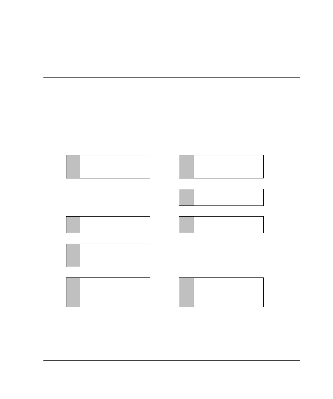
has an operating system installed and contains data. The flowcharts in Figure 2-1 and
Figure 2-2 summarize the installation procedures for the most common scenarios.
Install the controller
1
hardware (Chapter 3), if
it is not pre-installed.
Set the boot controller
5
(Chapter 6).
:
Create at least one
6
logical drive and format
it (Chapter 7).
:
Install the operating
7
system and device
drivers (Chapter 8).
Figure 2-1: Controller installation in a new system
. . . . . . .
. . . . . . .
. . . . . . .
Update the system
2
firmware (Chapter 4).
Update the controller
3
firmware (Chapter 5).
Configure the system
4
(Chapter 6).
Create additional logical
8
drives if desired and
format them
(Chapter 7).
:
:
Compaq Smart Array 5i Plus Controller and Battery Backed Write Cache Enabler User Guide 2-1
Page 20
Installation Overview
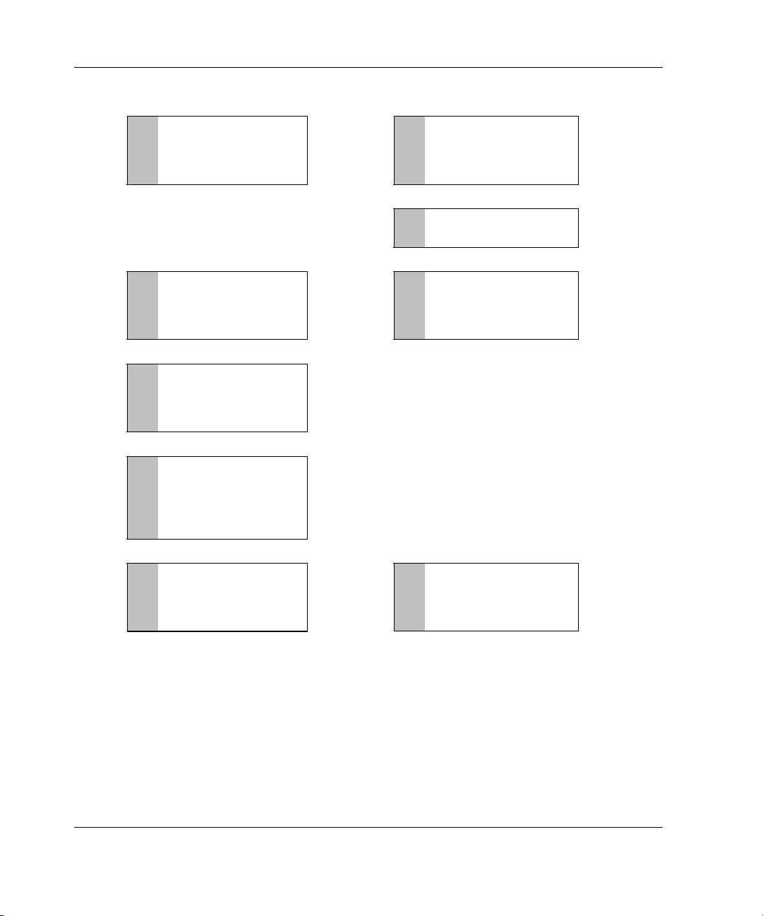
Back up data
1
(required if migrating
from a non-array
controller).
If using the System
5
Configuration Utility,
update the system
partition (Chapter 5).
Install the device
6
driver for your
operating system
(Chapter 8).
Update Compaq
7
Insight Manager
Agents if new versions
are available
(Chapter 8).
Update the system
2
. . . . . . . . .
. . . . . . . . .
:
:
firmware (Chapter 4).
Install the controller
3
hardware (Chapter 3).
Update the controller
4
firmware (Chapter 5).
:
:
:
Create and format
8
additional logical
drives if desired
(Chapter 7).
. . . . . . . . .
If migrating from a non-
9
array controller, restore
data from backup.
Figure 2-2: Controller installation in a previously
configured system
2-2 Compaq Smart Array 5i Plus Controller and Battery Backed Write Cache Enabler User Guide
Page 21

3
Installing the Smart Array 5i Plus Controller and
Battery Backed Write Cache Enabler
WARNING: To reduce the risk of personal injury or damage to the equipment,
be aware of the precautions you need to follow when setting up the system or
handling parts. A discharge of static electricity from a finger or other
conductor may damage system boards or other static-sensitive devices.
Many servers are also capable of producing energy levels that are considered
hazardous. These servers are to be serviced by qualified personnel trained to
deal with these hazards. Do not remove enclosures or attempt to bypass any
interlocks that may be provided for the purpose of removing these hazardous
conditions.
Consult the safety information and user documentation provided with your
server before attempting the installation.
To install the Smart Array 5i Plus Controller and Battery Backed Write Cache
Enabler:
1. Back up all data. This step is mandatory.
CAUTION: Back up all data stored on existing drives before installing the
controller. All data stored on non-array drives is destroyed when the new
controller is installed.
2. Close all applications.
3. Power down the server.
CAUTION: In systems using external data storage, be sure that the server is the
first unit powered down and the last to be powered back up. Doing this ensures
that the system will not erroneously mark the drives as failed.
Compaq Smart Start 5i Plus Controller and Battery Backed Write Cache Enabler User Guide 3-1
Page 22

Installing the Smart Array 5i Plus Controller and Battery Backed Write Cache Enabler
4. Power down any peripheral devices attached to the server.
5. Unplug the AC power cord from the outlet, then from the server.
6. Disconnect any peripheral devices from the server.
WARNING: To reduce the risk of personal injury from hot surfaces, allow
the internal system components and hot-plug hard drives to cool before
touching them.
7. Remove or open the access panel.
8. Install the Smart Array 5i Plus Controller and Battery Backed Write Cache
Enabler option. Refer to the documentation that ships with your server and with
the option kit.
9. Restore all data from the backup you performed in step 1.
CAUTION: Any information that was not backed up before installation is
permanently deleted when the system is powered up.
10. Use the Smart Array 5i Plus Controller utilities for configuration:
a. Run the ORCA utility to configure the first array and logical drive.
b. Install your operating system.
c. Run ACU-XE tools to configure and manage server storage with the
Smart Array 5i Plus Controller.
Installation is complete.
3-2 Compaq Smart Start 5i Plus Controller and Battery Backed Write Cache Enabler User Guide
Page 23

4
Updating the System Firmware
Before installing an array controller in a Compaq server, update the system firmware
by running the System ROMPaq
NOTE: This utility is not to be confused with the Options ROMPaq utility (see Chapter 5),
which is used to update the firmware on server options and SCSI drives.
The System ROMPaq utility has two main sources:
• The SmartStart and Support Software CD that is either shipped with your server
or available directly from Compaq
• The downloadable SoftPaq
If your server has a bootable CD-ROM drive, you can run System ROMPaq directly
from the CD. Otherwise, you must run System ROMPaq from a diskette created from
either the CD or from the SoftPaq file.
IMPORTANT: Compare the version numbers of the System ROMPaq utility from these two
sources. If the CD version is older, use the SoftPaq file instead.
If your system uses the System Configuration Utility (SCU), you may also need to
update the system partition to complete the system update.
TM
utility.
TM
file on the Compaq website
Compaq Smart Array 5i Plus Controller and Battery Backed Write Cache Enabler User Guide 4-1
Page 24

Updating the System Firmware
Running System ROMPaq from the CD
1. Boot the server from the SmartStart and Support Software CD.
2. On the Compaq System Utilities screen, select Run ROMPaq.
3. Follow the on-screen prompts and instructions to reprogram your system ROM.
Running System ROMPaq from Diskette
To run System ROMPaq from diskette, you must first create a System ROMPaq
diskette from the CD or from the appropriate SoftPaq file.
Creating a System ROMPaq Diskette from the CD
1. Insert the SmartStart and Support Software CD into the CD-ROM drive tray of a
server with a bootable CD-ROM drive.
2. Restart the server.
3. On the Compaq System Utilities screen, select Create Support Software.
4. On the Diskette Builder menu screen, scroll through the list and select System
ROMPaq Firmware Upgrade Diskette, and then click Next.
5. Click Create Diskettes Only, and then click Next.
6. Follow the remaining instructions on the screen to create the System ROMPaq
diskette.
7. To update the firmware, follow the procedure given in the section “Using the
Diskette.”
Creating a System ROMPaq Diskette from the SoftPaq File
1. Create a temporary directory on your hard drive.
2. Go to the Compaq website,
3. Locate the page containing the SoftPaq file for the System ROMPaq utility.
4. Click the link for the System ROMPaq SoftPaq file.
4-2 Compaq Smart Array 5i Plus Controller and Battery Backed Write Cache Enabler User Guide
www.compaq.com.
Page 25

5. Click Download, and then direct the download to the temporary directory that
you created.
6. Click Save.
7. Execute the downloaded SoftPaq file and follow the on-screen instructions to
create the System ROMPaq diskette.
8. To update the firmware, follow the procedure given in the section “Using the
Diskette.”
Using the Diskette
1. With the server powered down, place the System ROMPaq diskette in the
diskette drive.
2. Power up the server.
3. When the Welcome screen is displayed, press the Enter key.
4. When the Select A Device screen is displayed, select your server from the list of
programmable devices, and then press the Enter key.
The Select An Image screen is displayed, showing the following information:
Updating the System Firmware
Device to reprogram: your server
Current ROM revision: date of existing ROM version
Select Firmware Images: date of latest ROM version
5. Press the Enter key. The Caution screen is displayed.
6. Press the Enter key. The following message is displayed:
Reprogramming Firmware
Do not interrupt the reprogramming process. You will be notified when
reprogramming is complete.
7. When reprogramming has finished, press the Esc key to exit the utility.
8. Remove the System ROMPaq diskette and restart the server.
Compaq Smart Array 5i Plus Controller and Battery Backed Write Cache Enabler User Guide 4-3
Page 26

5
Updating the Controller Firmware
You can update the firmware on Compaq options by using the Options ROMPaq
utility. There are two versions of this utility: Options ROMPaq for Array Controllers
and Options ROMPaq for Internal (SCSI Attached) Drives.
If you purchased your server with an array controller already installed, you do not
need to run this utility during server installation. However, if you have older Smart
Array Controllers or other Compaq options (such as drives), run Options ROMPaq to
make sure that these devices have the latest firmware. Compaq recommends that you
run the latest Options ROMPaq on all Compaq array controllers whenever new
versions of the utility are released.
The Options ROMPaq utility has two main sources:
• Smart Array Controller Support Software CD
• The downloadable SoftPaq file on the Compaq website
If your server has a bootable CD-ROM drive, you can run Options ROMPaq directly
from the Smart Array Controller Support Software CD. Otherwise, you must run
Options ROMPaq from a diskette created from the CD or from the SoftPaq file.
IMPORTANT: Compare the version numbers of the Options ROMPaq utility from these two
sources. If the CD versions are older, use the SoftPaq file instead.
Compaq Smart Array 5i Plus Controller and Battery Backed Write Cache Enabler User Guide 5-1
Page 27

Updating the Controller Firmware
Running Options ROMPaq from the Smart Array Controller Support Software CD
1. Place the Smart Array Controller Support Software CD in the server CD-ROM
drive.
2. Restart the server.
3. When the Compaq System Utilities screen is displayed, select Run Options
ROMPaq and then press the Enter key.
4. When the Welcome screen is displayed, press the Enter key.
5. On the Select A Device screen, select All Compaq Smart Array nnnn
Controller(s)
key.
6. The action that you must now take depends on the message on the screen:
— If the screen message reads as follows, press the Enter key, and then go to
step 8 of these instructions:
The ROM image files found for the device selected are not
newer than the current ROM image
from the list of programmable devices, and then press the Enter
— If the ROM firmware currently on the controller is older than that on the
Options ROMPaq diskette, then the screen message reads as follows:
Device to reprogram: All Compaq Smart Array nnnn
Controller(s)
Controller(s) Current ROM revision: Compaq Smart Array
nnnn Controller x.xx
Select Firmware Images: Compaq Smart Array nnnn
Controller y.yy
In this case, press the Enter key and then go to step 7.
7. Review the information on the Caution screen, and then press the Enter key to
reprogram the controller ROM.
The following message is displayed:
Reprogramming Firmware
Do not interrupt the reprogramming process. You will be notified when
reprogramming is complete.
5-2 Compaq Smart Array 5i Plus Controller and Battery Backed Write Cache Enabler User Guide
Page 28

Updating the Controller Firmware
8. When reprogramming of the controller ROM is finished, you can reprogram
more options or exit the utility.
— To reprogram another Compaq option, press the Enter key, and then repeat
steps 5 through 7.
— If you have finished reprogramming Compaq options, press the Esc key to
exit the utility.
9. Remove the CD and restart the server.
Running Options ROMPaq from Diskettes
To run Options ROMPaq from diskette, first create Options ROMPaq diskettes from
one of the CDs or from the appropriate SoftPaq file.
Creating Diskettes Using the Smart Array Controller Support Software CD
1. Insert the Smart Array Controller Support Software CD into the server CD-ROM
drive tray.
2. Open the OPTRMDSK folder on the CD and execute the QRST5.EXE file.
3. Follow the on-screen prompts to create the set of Options ROMPaq diskettes.
4. To complete the firmware update, follow the procedure given in the section
“Using the Diskettes.”
Creating Diskettes Using the SmartStart and Support Software CD
1. Insert the SmartStart and Support Software CD into the CD-ROM drive tray of a
server with a bootable CD-ROM drive.
2. Restart the server.
3. On the Compaq System Utilities screen, select Create Support Software.
4. On the Diskette Builder menu screen, scroll through the list and select Options
ROMPaq, and then click Next.
5. Click Create Diskettes Only and then click Next.
Compaq Smart Array 5i Plus Controller and Battery Backed Write Cache Enabler User Guide 5-3
Page 29

Updating the Controller Firmware
6. Follow the remaining on-screen instructions to create the Options ROMPaq
diskettes.
7. To complete the firmware update, follow the procedure given in the section
“Using the Diskettes.”
Creating Diskettes Using the SoftPaq File
1. Create a temporary directory on your hard drive.
2. On the Compaq website, locate the page containing the SoftPaq file for the
Options ROMPaq utility.
3. Click the link for the Options ROMPaq SoftPaq file.
4. Click Download, and direct the download to the temporary directory that you
created.
5. Click Save.
6. Execute the downloaded SoftPaq file and follow the on-screen instructions to
create the diskette. Up to six diskettes are needed for the Options ROMPaq
SoftPaq file.
7. To complete the firmware update, follow the procedure given in the section
“Using the Diskettes.”
Using the Diskettes
1. Be sure that the server is off.
2. Insert the first Options ROMPaq diskette into the diskette drive.
3. Restart the server.
4. When the Welcome screen is displayed, press the Enter key. The Select a
Device screen is displayed.
If the controller that you want to update the firmware for is on the list of
programmable devices, select it and press the Enter key. (If it is not present, you
are prompted to insert the remaining diskettes for devices not listed on the first
diskette.)
5. The action that you must now take depends on the message on the screen:
5-4 Compaq Smart Array 5i Plus Controller and Battery Backed Write Cache Enabler User Guide
Page 30

Updating the Controller Firmware
— If the screen message reads as follows, press the Enter key, and then go to
step 8 of these instructions:
The ROM image files found for the device selected are not
newer than the current ROM image
— If the ROM firmware currently on the controller is older than that on the
Options ROMPaq diskette, then the screen message reads as follows:
Device to reprogram: All Compaq Smart Array nnnn
Controller(s)
Controller(s) Current ROM revision: Compaq Smart Array
nnnn Controller x.xx
Select Firmware Images: Compaq Smart Array nnnn
Controller y.yy
In this case, press the Enter key and then go to step 7.
6. Review the information on the Caution screen, and then press the Enter key to
reprogram the controller ROM.
The following message is displayed:
Reprogramming Firmware
Do not interrupt the reprogramming process. You will be notified when
reprogramming is complete.
7. When the reprogramming of the controller ROM is finished, you can reprogram
more options or exit the utility.
— To reprogram another Compaq option, press the Enter key, and then repeat
steps 5 through 7.
— If you have finished reprogramming Compaq options, press the Esc key to
exit the utility.
8. Remove the Options ROMPaq diskette and restart the server.
Updating the System Partition
If you are installing the controller on a server that was previously configured with
SCU, you must now use this utility to update the system partition.
NOTE: If your server uses the ROM-Based Setup Utility (RBSU), you do not need to run SCU.
Compaq Smart Array 5i Plus Controller and Battery Backed Write Cache Enabler User Guide 5-5
Page 31

Updating the Controller Firmware
SCU is provided on both the SmartStart and Support Software CD and the Smart
Array Controller Support Software CD. Compare the SCU version numbers from
these two sources and use the most recent version.
NOTE: Before updating NetWare volumes or partitions, remember these tips to optimize
system performance:
• If you want to use hardware-based RAID, do not select mirroring while using
INSTALL.NLM or NWCONFIG.NLM.
• Novell recommends that you create volumes with a 64-kbyte block size to decrease the
amount of RAM required to mount the volume, and use the Block Sub-Allocation feature
to allow disk space to be allocated more efficiently.
• Linear memory provides the best system performance in the NetWare environment. If you
previously used SCU to configure your server, this option would have been the default. To
check that the system is using linear memory, run SCU and view the Compaq memory
settings. Be sure that a linear option is selected under the Base Memory option.
1. Restart the server from the CD.
2. If the CD-ROM drive is bootable, go to step 5. Otherwise, locate the CD-ROM
drive:\SYSCFDSK\US directory, run the file QRST5.EXE, and follow the onscreen instructions to create four SCU diskettes.
3. Insert SCU diskette #1 into the server diskette drive.
4. Restart the system.
5. Select System Configuration Utility from the menu or list of icons that is
displayed.
6. Follow the on-screen instructions to update or create and populate a system
partition.
7. Exit from the SCU.
If the server does not reboot or a CD error message is displayed, press the
Ctrl+Alt+Del keys to continue and reboot the server.
5-6 Compaq Smart Array 5i Plus Controller and Battery Backed Write Cache Enabler User Guide
Page 32

When installing a controller in a new system, perform these tasks after installing the
controller and updating the controller firmware:
• Configure the system by using either the ROM-Based Setup Utility (RBSU) or
the System Configuration Utility (SCU), following the procedure given in the
server user guide.
• Set the boot controller by using RBSU, or the Option ROM Configuration for
Arrays (ORCA) utility (described in this chapter).
• Create at least one logical drive by using ORCA or ACU (as described in
Chapter 7).
Using RBSU
RBSU is a system configuration utility that is embedded in the system ROM, and is
customized for the server on which it is installed. RBSU is updated by using System
ROMPaq.
6
Configuring the System
IMPORTANT: Not all servers support RBSU.
To use RBSU:
1. Power up the server.
Compaq Smart Array 5i Plus Controller and Battery Backed Write Cache Enabler User Guide 6-1
Page 33

Configuring the System
2. Press the F9 key when prompted during system startup.
The ROM-Based Setup Utility menu screen is displayed.
Figure 6-1: RBSU menu screen
3. Configure your system. (For detailed instructions, refer to the Compaq ROM-
Based Setup Utility User Guide.)
4. Set the boot controller by selecting Boot Controller Order on the RBSU menu
screen and following the on-screen prompts.
5. When you have finished using the utility, press the Esc key, and then press the
F10 key to confirm that you want to exit RBSU.
6-2 Compaq Smart Array 5i Plus Controller and Battery Backed Write Cache Enabler User Guide
Page 34

Using ORCA
Part of the startup sequence of a server is the Power-On Self-Test (POST). If the
array controller in the server supports ORCA, POST temporarily halts and an ORCA
prompt message is displayed for about five seconds. (If ORCA is not supported, the
prompt message is not displayed and the system continues with the startup sequence.)
1. Power up the server and let the system startup sequence begin.
2. While the prompt message is on the screen, press the F8 key to start ORCA.
3. On the Option ROM Configuration for Arrays Main Menu screen, select
Select Boot Controller and follow the prompts to set the boot controller for the
system.
If you want to use ORCA to create logical drives at this point, you do not need to exit
the utility yet. Continue using ORCA as described in Chapter 7.
Configuring the System
Compaq Smart Array 5i Plus Controller and Battery Backed Write Cache Enabler User Guide 6-3
Page 35

7
Configuring an Array
Compaq provides four utilities for configuring an array:
• Option ROM Configuration for Arrays (ORCA)—a simple ROM-based
configuration utility that runs on all operating systems
• Array Configuration Utility (ACU)—a versatile configuration utility that
provides maximum control over configuration parameters
• Array Configuration Utility-XE (ACU-XE)—a browser-based version of ACU
that can be used remotely on systems that are also running Compaq Insight
Manager XE
• NetWare Online Array Configuration (CPQONLIN) Utility—a menu-driven
utility for NetWare
The following limitations apply to all configuration methods:
• For the most efficient use of drive space, do not mix drives of different capacity
within the same array. Each configuration utility treats all physical drives in an
array as if they have the same capacity as the smallest drive in the array. Excess
capacity of larger drives is wasted because it is unavailable to the array.
• Only one online spare drive can be assigned per array.
• The probability that an array will experience a hard drive failure increases with
the number of hard drives in the array (see Appendix D). If you configure an
array with RAID 5, keep the probability of failure acceptably low by using no
more than 14 drives.
Compaq Smart Array 5i Plus Controller and Battery Backed Write Cache Enabler User Guide 7-1
Page 36

Configuring an Array
For more information about ACU-XE, refer to the Compaq Array Configuration
Utility XE User Guide. For background information about drive arrays and
fault-tolerance (RAID) methods, see Appendix C.
Table 7-1: Comparison of Utilities for Configuring an Array
ACU ACU-XE CPQONLIN ORCA
Uses a graphical interface + + 0 0
Available in languages other than English + + 0 0
Executable at any time + + + 0
Available on CD + + + 0
Uses a wizard to suggest the optimum
configuration for an unconfigured controller
Describes configuration errors + + 0 0
Supports these operating systems:
Windows 2000 + + 0 +
Windows NT + 0 0 +
NetWare + + + +
Linux + + 0 +
++ + 0
Allows these procedures:
Creation and deletion of arrays, logical drives + + + +
Assignment of RAID level + + + +
Assignment of a spare drive + + + +
Sharing of a spare drive among several arrays + + + 0
Setting of stripe size + + + 0
Migration of RAID level or stripe size + + + 0
Configuration of controller settings + + + 0
Expansion of an array + + + 0
Creation of multiple logical drives per array + + 0 0
Setting of boot controller 0 0 0 +
7-2 Compaq Smart Array 5i Plus Controller and Battery Backed Write Cache Enabler User Guide
Page 37

Using ORCA
When a computer system is powered up, part of the startup sequence is the Power-On
Self-Test (POST). Any array controllers that are in the system are initialized while
POST is running. If the array controller supports ORCA, POST temporarily halts and
an ORCA prompt message is displayed for about five seconds. (If ORCA is not
supported, the prompt message is not displayed and the system continues with the
startup sequence.)
While the prompt is displayed, press the F8 key to start ORCA. The Option ROM
Configuration for Arrays Main Menu screen is displayed, allowing you to select
the boot controller for the system, or to create, view, or delete a logical drive.
Configuring an Array
Figure 7-1: ORCA main menu screen
To create a logical drive:
1. Choose Create Logical Drive.
The screen displays a list of all available (unconfigured) physical drives and the
valid RAID options for your system.
NOTE: You can create only one logical drive at a time.
2. Use the arrow keys, space bar, and tab key to navigate around the screen and set
up your logical drive, including a spare drive if required.
Compaq Smart Array 5i Plus Controller and Battery Backed Write Cache Enabler User Guide 7-3
Page 38

Configuring an Array
NOTE: ORCA allows only one array to use a given online spare.
3. Press the Enter key to accept the settings.
4. At the next screen, press the F8 key to confirm your settings and save the new
configuration.
5. After several seconds, the Configuration Saved screen is displayed. Press the
Enter key to continue.
You can now create another logical drive on any remaining physical drives by
repeating the previous steps. ORCA allows only one logical drive to be created per
array; to create an array containing several logical drives, use ACU or ACU-XE.
NOTE: Raw logical drives are invisible to the operating system. To make the new logical
drives available for data storage, format the logical drive using the instructions given in your
operating system documentation.
Using ACU
ACU is located on the Smart Array Controller Support Software CD and on the
SmartStart and Support Software CD. You can run ACU directly from one of these
CDs, or—if the server you are configuring is running the Microsoft Windows NT or
Windows 2000 operating system—you can download ACU onto your server and run
it online.
When you start ACU, it checks the configuration of every controller and drive array.
If an array is not configured optimally, the ACU configuration wizard opens and
guides you through the configuration process. The wizard also helps you to configure
any new controllers, assign unused physical drives to existing arrays (without
destroying data), and configure any unused space present on an array into another
logical drive. ACU allows you to create up to 32 logical drives per array.
If a problem arises during the configuration process, ACU displays an error message
describing the problem. If the following warning message is displayed along with an
error code number, call your local Compaq technical support number for assistance:
Internal Error Has Occurred
7-4 Compaq Smart Array 5i Plus Controller and Battery Backed Write Cache Enabler User Guide
Page 39

See the “About This Guide” section for technical support phone numbers.
You can view context-sensitive online help for each screen by pressing the F1 key or
clicking Help. The status bar at the bottom of the screen also displays messages
describing the current selection.
NOTE: Raw logical drives are invisible to the operating system. To make the new logical
drives available for data storage, format the logical drive using the instructions given in your
operating system documentation.
Running ACU from CD
This method of running ACU is valid for Windows NT, Windows 2000, Linux, and
Novell NetWare operating systems.
1. Insert the CD into the CD-ROM drive and restart the server.
2. When the CD menu is displayed, double-click the ACU icon.
3. Configure your array (see the “Typical Manual Configuration Procedures”
section for details if you do not want to use the wizard).
4. Remove the CD and restart the server to activate the new settings.
Configuring an Array
Running ACU while Online
You can run ACU online with the Windows NT or Windows 2000 operating system.
1. Insert the CD into the CD-ROM drive of the server and follow the on-screen
instructions to download the utility.
2. When installation is complete, click Start, and then select Compaq System
Tools.
3. Double-click ACU.
Compaq Smart Array 5i Plus Controller and Battery Backed Write Cache Enabler User Guide 7-5
Page 40

Configuring an Array
ACU Screen Descriptions
NOTE: The screenshots shown with these descriptions are merely examples. The exact
appearance of your screen depends on the controller and hard drives that you use. For
example, the number of ports on the controller and the RAID levels available may be different
in your case.
Main Configuration Screen
This ACU Main Configuration screen is the first to be displayed after the
configuration wizard has finished or been bypassed.
Figure 7-2: Example of ACU Main Configuration screen
This screen contains the following regions:
• Menu bar
• Controller Selection box
• Logical Configuration View window
• Drive View box
• Controller box
• Array box
• Logical Drive box
7-6 Compaq Smart Array 5i Plus Controller and Battery Backed Write Cache Enabler User Guide
Page 41

Configuring an Array
Menu Bar
The menu bar at the top of the ACU Main Configuration screen contains the
following drop-down menus:
• Controller—Allows you to select a controller, refresh the screen, save or clear a
configuration, create an array, or exit the program. Other menu items give access
to settings, advanced features, information, and the configuration wizard.
• Array—Allows you to delete or modify an array, or to expand array capacity,
create logical drives, and view array information.
• Drive—Allows you to delete or change logical drives and to view drive
information.
• View—Allows you to switch between Physical Configuration View and
Logical Configuration View.
• Help—Allows you to access online help.
Controller Selection Box
This box provides a drop-down list of the controllers installed in the system. When
you select a controller, details of the drives and arrays that are connected to the
controller are shown in the Configuration View window.
Figure 7-3: Controller Selection box
Physical/Logical Configuration View Window
The Physical/Logical Configuration View window shows the drives and arrays that
are connected to the selected controller. The Drive View radio buttons below the
Configuration View window let you switch between the physical and logical
configuration views.
Figure 7-4 shows a typical physical configuration view, and Figure 7-2 shows a
typical logical configuration view.
Compaq Smart Array 5i Plus Controller and Battery Backed Write Cache Enabler User Guide 7-7
Page 42

Configuring an Array
Figure 7-4: Physical Configuration View window
NOTE: Selecting any item in the Configuration View window will cause the corresponding
hard drive tray LEDs to blink. This feature is useful for identifying all physical drives in an array
or logical drive, all drives on a controller, or a specific physical drive.
Drive View Box
Use the radio buttons in this box to display a logical or physical configuration view in
the Configuration View window.
Figure 7-5: Drive View box
Controller Box
The buttons in the Controller box are activated when you select a controller in the
Controller Selection box.
7-8 Compaq Smart Array 5i Plus Controller and Battery Backed Write Cache Enabler User Guide
Page 43

Configuring an Array
Figure 7-6: Controller box
Click one of these buttons to display the Controller Settings screen or the Create
Drive Array screen.
Array Box
The buttons in the Array box are activated when you select an array in the
Configuration View window.
Figure 7-7: Array box
Click one of these buttons to display the Modify Drive Array screen, the Expand
Array screen, or the Create Logical Drive screen.
Logical Drive Box
The buttons in the Logical Drive box are activated when you select a logical drive in
the Configuration View window.
Compaq Smart Array 5i Plus Controller and Battery Backed Write Cache Enabler User Guide 7-9
Page 44

Configuring an Array
Figure 7-8: Logical Drive box
Click one of these buttons to display the Modify Logical Drive screen, the Migrate
Logical Drive screen, or the Extend Logical Drive screen.
More Information Button
Click More Information in the bottom right of the ACU Main Configuration
screen to get a detailed description of the item that is selected in the Configuration
View window.
Secondary Screens
Controller Settings Screen
To display this screen, click Settings in the Controller box (Figure 7-6) on the ACU
Main Configuration screen.
This screen allows you to set the rebuild priority, expand priority, and accelerator
read/write ratio.
Figure 7-9: Controller Settings screen
7-10 Compaq Smart Array 5i Plus Controller and Battery Backed Write Cache Enabler User Guide
Page 45

Configuring an Array
The settings that you use for Rebuild Priority and Expand Priority will not affect
the performance of an idle system. However, they will affect performance on a busy
system:
• On the High settings, the controller will give preference to the rebuild or
expansion process over normal I/O operations.
• On the Low settings, the controller will rebuild or expand only when the
controller is idle. However, this setting leaves the array vulnerable to drive
failure for a longer time than the High setting.
The Accelerator Ratio setting determines the amount of memory allocated to the
read and write caches. Some applications may perform better with a larger write
cache; others may perform better with a larger read cache. If your controller does not
have a battery backed array accelerator, only read cache will be available (the ratio
will always be 100% Read / 0% Write).
NOTE: If you optimize the Accelerator Ratio setting, you may also want to change the Stripe
Size setting. See the “Create Logical Drive Screen” section and Table 7-2 and Table 7-3 for
details.
Create Drive Array Screen
To display this screen, click Create Array in the Controller box (Figure 7-6) on the
ACU Main Configuration screen. The left panel of the Create Drive Array screen
shows all drives that are attached to the controller that was selected on the ACU
Main Configuration screen.
Compaq Smart Array 5i Plus Controller and Battery Backed Write Cache Enabler User Guide 7-11
Page 46

Configuring an Array
Figure 7-10: Create Drive Array screen
The three buttons in the middle of this screen are:
• Assign Drive To Array
• Remove Drive From Array
• Assign Spare To Array
Modify Drive Array Screen
To display this screen, click Modify in the Array box on the ACU Main
Configuration screen. This screen resembles the Create Drive Array screen
(Figure 7-10), and allows you to change the configuration of your array.
Expand Array Screen
To display this screen, click Expand in the Array box on the ACU Main
Configuration screen.
The Expand Array screen resembles the Create Drive Array screen (Figure 7-10).
It allows you to add more hard drives to an array that has already been configured.
The extra capacity can be used to build another logical drive on the array, or to
extend a logical drive that already exists on the array.
7-12 Compaq Smart Array 5i Plus Controller and Battery Backed Write Cache Enabler User Guide
Page 47

Configuring an Array
Create Logical Drive Screen
To display this screen, click Create Logical Drive in the Array box (Figure 7-7) on
the ACU Main Configuration screen.
This screen allows you to select the fault-tolerance method, enable the array
accelerator (if present), and set the stripe size and logical drive size on a new logical
drive.
CAUTION: Do not use this screen to modify a pre-existing logical drive, since this
method does not preserve user data. Instead, to change the RAID level and stripe
size on a logical drive that already contains user data, click Migrate to reach the
Migrate RAID/Stripe Size screen (Figure 7-13).
Figure 7-11: Create Logical Drive screen
Three features on this screen merit further description:
• Stripe Size box
• Logical Drive Size box
• Advanced button
Compaq Smart Array 5i Plus Controller and Battery Backed Write Cache Enabler User Guide 7-13
Page 48

Configuring an Array
The Stripe Size box has a drop-down menu that lets you select the width of a data
stripe. (This width corresponds to the size of a data block on each hard drive in the
logical volume, as described in Appendix D).
Each RAID level supports several stripe widths (Table 7-2); the default stripe size
initially displayed by ACU is chosen for optimum performance under the most
common operating conditions. Table 7-3 suggests how to optimize the stripe width
for different types of application.
Table 7-2: Supported Stripe Sizes for a Given RAID Level
Fault Tolerance Level Supported Stripe Sizes (KB) Default (KB)
RAID 0 8, 16, 32, 64, 128, 256 128
RAID 1 or 1+0 8, 16, 32, 64, 128, 256 128
RAID 5 8, 16, 32, 64 16
Table 7-3: Optimum Stripe Size for a Given Application
Type of Server Application Suggested Stripe Size Change
Mixed read/write Accept the default value
Mainly sequential read (such
as audio/video applications)
Mainly write (such as image
manipulation applications)
Use larger stripe sizes for best
performance
Use smaller stripes for RAID 5
Use larger stripes for RAID 0, RAID 1+0,
RAID 1
The Logical Drive Size box shows how much drive capacity is available on the
selected logical drive when using the chosen RAID level. The left side of the slider
scale shows how much drive capacity is available for data storage, while the right
side indicates how much capacity is required for storing parity or mirrored
information. (RAID overhead is not needed for RAID 0.)
The default logical drive size first shown in this box is the maximum available for
your drive array. To create more than one logical drive on the array, reduce the
logical drive size by typing a smaller number in the scroll box. ACU allows you to
create up to 32 logical drives per array.
7-14 Compaq Smart Array 5i Plus Controller and Battery Backed Write Cache Enabler User Guide
Page 49

Configuring an Array
Click Advanced to display the Advanced Features screen, where you can enable or
disable the maximum boot size for a logical drive. The default boot size is 32 sectors
(16 kbytes) per track, and the maximum boot size is 63 sectors per track.
Figure 7-12: Advanced Features screen
Some operating systems need to use the maximum boot size to be able to create large
boot partitions. For example, enabling the maximum boot size on a logical drive in
the Windows NT 4.0 operating system allows you to create a bootable partition with
a maximum size of 8 GB.
NOTE: Enabling the maximum boot size may decrease performance of the logical drive.
Modify Logical Drive Screen
To display this screen, click Modify in the Logical Drive box (Figure 7-8) on the
ACU Main Configuration screen. This screen resembles the Create Logical Drive
screen (Figure 7-11), and lets you change the parameters of an existing logical drive
while online, without causing data loss.
Migrate RAID/Stripe Size Screen
To display this screen, click Migrate in the Logical Drive box (Figure 7-8) on the
ACU Main Configuration screen. It allows you to change the stripe width (block
size) or RAID level of an existing logical drive while online, without causing data
loss.
Compaq Smart Array 5i Plus Controller and Battery Backed Write Cache Enabler User Guide 7-15
Page 50

Configuring an Array
Figure 7-13: Migrate RAID/Stripe Size screen
Extend Logical Drive Screen
To display this screen, click Extend in the Logical Drive box (Figure 7-8) on the
ACU Main Configuration screen. This screen allows you to increase the capacity of
a logical drive while the system is online, without disruption of data.
IMPORTANT: Not all operating systems support online capacity extension. See the section
“Extending Logical Drive Capacity” for more information.
Figure 7-14: Extend Logical Drive screen
7-16 Compaq Smart Array 5i Plus Controller and Battery Backed Write Cache Enabler User Guide
Page 51

Typical Manual Configuration Procedures in ACU
When you launch ACU to configure a new array, a configuration wizard opens to
allow rapid, automatic array configuration. However, you can bypass the wizard and
manually:
• Create a new array
• Expand the capacity of an array
• Extend the capacity of a logical drive
• Migrate to a different RAID level or stripe size
Creating a New Array
There are three stages in the procedure for manually creating a new array:
1. Configure the controller settings.
2. Assign physical drives of the same size to an array.
3. Create one or more logical drives on the array.
Configuring an Array
For this example, assume that you have four 4.3-GB drives and two 9.1-GB drives
connected to your controller. You want to make two arrays:
• Array A: three 4.3-GB drives with the fourth 4.3-GB drive used as a spare. This
array is to be configured with RAID 5 fault tolerance.
• Array B: two 9.1-GB drives in a RAID 1 fault-tolerance configuration.
Configuring the Controller Settings
1. On the ACU Main Configuration screen, select the controller to be used from
the drop-down list in the Controller Selection box. (Alternatively, click
Controller on the menu bar, and then click Select.)
2. Click Controller Settings.
The Controller Settings screen is displayed (Figure 7-9).
3. Select the rebuild priority, expand priority, and accelerator ratio.
4. Click Done to return to the ACU Main Configuration screen.
Compaq Smart Array 5i Plus Controller and Battery Backed Write Cache Enabler User Guide 7-17
Page 52

Configuring an Array
Assigning Physical Drives of the Same Size to an Array
1. Click Create Array in the Controller box.
The Create Drive Array screen is displayed (Figure 7-10).
2. Select the drives that you want to build the array with from the drives that are
shown in the left panel.
IMPORTANT: Do not assign a group of physical drives to the same array unless they are
of the same capacity. If the drives have different capacities, the excess capacity of the
larger drives cannot be used by the array and is wasted.
For this example, select the three drives on Port 1 with SCSI IDs 0, 1, and 2.
3. Click Assign Drive(s) to Array (Figure 7-19) in the middle of the screen.
NOTE: The probability that an array will experience a drive failure increases with the
number of drives in the array. Compaq recommends that no more than 14 drives be used
per array in RAID 5 configurations.
4. Select the drive at Port 1: SCSI ID 3 and click Assign Spare to Array in the
middle of the screen.
NOTE: You can assign the same spare drive to several arrays. In such a case, verify that
the capacity of the spare is enough for each array. (Spare drives must have a capacity no
less than that of other drives in the same array.)
The Create Drive Array screen now looks like Figure 7-15.
7-18 Compaq Smart Array 5i Plus Controller and Battery Backed Write Cache Enabler User Guide
Page 53

Configuring an Array
Figure 7-15: Example Array A with Spare
5. Click Done to return to the ACU Main Configuration screen.
The Logical Configuration View window now looks like Figure 7-16.
Figure 7-16: Logical Configuration View of
Example Array
6. Select the controller icon, and then click Create Array to create Array B.
7. Repeat the previous steps to assign both 9.1-GB drives to Array B.
8. Click Done to return to the ACU Main Configuration screen.
Compaq Smart Array 5i Plus Controller and Battery Backed Write Cache Enabler User Guide 7-19
Page 54

Configuring an Array
In this example, each array was created using drives from the same SCSI port. You
can get better performance by installing the correct capacity drives in other ports
before running the ACU, and then selecting drives from more than one port to build
the array.
Creating One or More Logical Drives on the Array
1. Select Array A or Unused Space under Array A in the Logical Configuration
View window (Figure 7-16).
2. Click Create Logical Drive in the Array box.
3. On the Create Logical Drive screen (Figure 7-11), select RAID 5.
4. Click Enable Array Accelerator, if it is active.
5. Change the stripe size, if desired (and if possible for your controller model).
6. The default values in the Logical Drive Size box will create a single logical drive
on the array. For this example, accept the default values.
7. Click Done to return to the ACU Main Configuration screen.
8. Save the new settings by clicking Controller on the menu bar and selecting Save
Configuration.
9. Create a logical drive on Array B by selecting Array B or Unused Space under
Array B in the Logical Configuration View window and following the previous
steps. This time, select RAID 1 as the fault tolerance method. Save the
configuration as before.
The ACU Main Configuration screen now looks like Figure 7-17.
7-20 Compaq Smart Array 5i Plus Controller and Battery Backed Write Cache Enabler User Guide
Page 55

Figure 7-17: Example array – Logical Configuration
View window, two arrays
NOTE: The capacity shown for each logical drive is the free capacity available for data
storage. This value excludes the amount used for fault tolerance.
Expanding Array Capacity
Configuring an Array
Array capacity expansion is the addition of storage capacity to a pre-existing array.
The capacity of logical drives on the array does not change, and existing data is not
changed.
During capacity expansion, ACU automatically redistributes existing logical drives
across all of the physical drives in the expanded array. If the array being expanded
has more than one logical drive, data is redistributed one logical drive at a time.
Newly created logical drives are not available until capacity expansion has finished.
CAUTION: Do not exchange the controller or array accelerator board during array
capacity expansion. Interrupting expansion in this way causes irretrievable data loss.
NOTE: The expansion process takes about 15 minutes per gigabyte. A logical drive is
unavailable for any other process while it is undergoing an expansion, and no other logical
drive in the system can be expanded, extended, or migrated during this time.
There are three stages in the procedure for expanding an array:
Compaq Smart Array 5i Plus Controller and Battery Backed Write Cache Enabler User Guide 7-21
Page 56

Configuring an Array
1. Back up all data on the array. Although array expansion is unlikely to cause data
loss, observing this precaution will provide additional data protection.
2. Install the new physical drives.
IMPORTANT: Do not assign a group of physical drives to the same array unless they are
of the same capacity. If the drives have different capacities, the excess capacity of the
larger drives cannot be used by the array and is wasted.
3. Assign the new physical drives to an existing array. When the expansion process
is complete, the extra capacity can be used to increase the size of an existing
logical drive (see the “Extending Logical Drive Capacity” section) or to create a
new logical drive.
For example, consider a controller with these two arrays:
• Array A—three 4.3-GB drives in a RAID 5 configuration, no spare.
• Array B—two 9.1-GB drives in a RAID 1 configuration, no spare.
Now you install a 4.3-GB drive, and want to expand Array A to include this new
drive. This scenario is represented in Figure 7-18.
Figure 7-18: Array expansion example
To expand Array A and create a second logical drive on this array:
1. Select Array A in the Logical Configuration View window.
7-22 Compaq Smart Array 5i Plus Controller and Battery Backed Write Cache Enabler User Guide
Page 57

Configuring an Array
2. Click Expand in the Array box.
3. In the left-hand panel of the Expand Array A dialog box, select the unassigned
4.3-GB drive.
4. Click Assign Drive to Array in the middle of the screen.
Figure 7-19: Assign Drive to Array button
5. Click Next at the bottom of the screen. The screen shown in Figure 7-20 is
displayed.
Figure 7-20: Expansion Wizard – Create Logical Drives
screen
6. Click Create Logical Drive.
7. Set the fault tolerance, stripe size, array accelerator, and size for the second
logical drive that you want to create on Array A.
8. Click Done to return to the Create Logical Drives screen.
9. Click Done again to return to the ACU Main Configuration screen.
10. On the menu bar, select Controller, Save Configuration. The settings for the
second logical drive are saved and the capacity expansion process begins.
Compaq Smart Array 5i Plus Controller and Battery Backed Write Cache Enabler User Guide 7-23
Page 58

Configuring an Array
NOTE: The second logical drive is not accessible until the capacity expansion process on
Logical Drive 1 is complete. Also, Logical Drive 1 is unavailable for any other process
while it is undergoing an expansion, and no other logical drive in the system can be
expanded, extended, or migrated during this time.
Extending Logical Drive Capacity
Logical drive capacity extension is the addition of storage capacity to an existing
logical drive. For logical drive extension to be possible, sufficient free capacity must
exist on the array. If necessary, create free capacity by deleting existing logical drives
on the array or by performing an array expansion (see “Expanding Array Capacity”).
Windows NT 4.0 and NetWare 5.x operating system support online logical drive
capacity extension. Some operating systems also support offline capacity extension,
which is carried out by backing up all data, reconfiguring the array, and restoring the
data. Before extending logical drives, check the operating system documentation for
current information, or contact your operating system vendor.
NOTE: The extension process takes about 15 minutes per gigabyte. A logical drive is
unavailable for any other process while it is undergoing an extension, and no other logical
drive in the system can be expanded, extended, or migrated during this time.
To extend the capacity of a logical drive:
1. Back up all data on the array. Although array expansion is unlikely to cause data
loss, observing this precaution will provide additional data protection.
2. Select the logical drive in the Logical Configuration View window.
3. Click Extend in the Logical Drive box.
The Extend Logical Drive screen displays the current capacity and overhead of
the selected logical drive. The unshaded region on the slider scale shows the free
capacity on the array that is available for extension.
4. Move the slider control to increase the size of the logical drive.
NOTE: You cannot reduce the size of the logical drive from this screen.
5. Click Done to return to the ACU Main Configuration screen.
7-24 Compaq Smart Array 5i Plus Controller and Battery Backed Write Cache Enabler User Guide
Page 59

6. To save the logical drive settings, click Controller on the menu bar and select
Save Configuration.
A progress bar in the lower right-hand corner of the screen shows the status of
the extension process.
7. Make the extra capacity of the logical drive available to the operating system by
one of the following methods:
— Create a new partition in the logical drive by using the operating system
partitioning software.
— Increase the size of an existing partition by using the operating system
partitioning software or third-party partitioning tools.
Migrating RAID Level or Stripe Size
NOTE: Before migrating the stripe size, check that the available memory on the array
accelerator is no smaller than the lowest common multiple of the total stripe sizes of the two
different configurations.
For example, consider the change from an 11-drive RAID 5 logical volume to a 14-drive
RAID 1+0 logical volume. If each configuration uses the corresponding default stripe width, the
block size changes from 16 kbytes per stripe to 128 kbytes per stripe.
• A full stripe in the RAID 5 configuration contains 160 kbytes (ten of the drives contain user
data; one drive contains parity data).
Configuring an Array
• A full stripe in the RAID 1+0 configuration contains 896 kbytes.
The lowest common multiple of the two stripe sizes is 4480 kbytes, and this figure represents
the minimum amount of memory that must be available on the array accelerator.
To migrate to a different RAID level or stripe size:
1. Back up all data on the logical drive. Although migration is unlikely to cause
data loss, observing this precaution provides extra security. The backup data may
also be needed if the number of sectors needs to be increased (this fact will be
determined in step 8).
2. Verify that the array accelerator batteries (if present) are fully charged.
NOTE: The migration process takes about 15 minutes per gigabyte. A logical drive is
unavailable for any other process while it is undergoing migration, and no other logical
drive in the system can be expanded, extended, or migrated during this time.
Compaq Smart Array 5i Plus Controller and Battery Backed Write Cache Enabler User Guide 7-25
Page 60

Configuring an Array
3. If your controller has a battery backed write cache, check the Controller
Settings screen to confirm that the write cache is enabled.
4. Select the logical drive in the Logical Configuration View window.
5. Click Migrate in the Logical Drive box.
6. Change the RAID level by selecting the appropriate check box.
7. Change the stripe size (Table 7-3 gives the optimum stripe size for specific
situations).
8. Click Done to return to the ACU Main Configuration screen.
If you get a message stating that the number of sectors needs to be increased:
a. Delete the old logical volume.
b. Reconfigure the array as a new logical volume with the new fault-tolerance
method and stripe size that you had selected.
c. Copy the backed-up data (from step 1) onto the new logical volume.
9. To save the new settings, click Controller on the menu bar and select Save
Configuration.
Using CPQONLIN
The NetWare Online Array Configuration Utility (CPQONLIN) lets you configure
your drive arrays without shutting down your server. It also indicates when a drive
attached to the array controller has failed, is undergoing expansion, or is waiting
(queued) for expansion or rebuild.
To install CPQONLIN:
1. Load CPQRAID.HAM from the SmartStart and Support Software CD or the
Controller Support Software CD and diskettes. (Detailed instructions are given in
the README file on the CD.)
2. Load CPQONLIN.NLM from the same source.
3. Open CPQONLIN.NLM and follow the on-screen instructions.
7-26 Compaq Smart Array 5i Plus Controller and Battery Backed Write Cache Enabler User Guide
Page 61

Running CPQONLIN
1. Enter cpqonlin at the console prompt.
2. Use the arrow keys to highlight Array Configuration Utility, and then press the
Enter key.
3. From the list of controllers that is presented, select the one that you want to
configure.
— If no logical drives are configured for the controller, the auto-configuration
wizard screen (see Figure 7-21) is displayed.
— If logical drives are present on the controller, the manual configuration
screen (see Figure 7-22) is displayed.
Press the F1 key for online help at any time on either screen.
Automatic Configuration
Configuring an Array
Figure 7-21: CPQONLIN auto-configuration wizard
1. If the proposed logical configuration shown on the wizard screen is acceptable,
highlight the fault tolerance level that you want for the logical drive and press the
Enter key. Otherwise, select Custom Configuration and continue the procedure
as described in the “Manual Configuration” section.
2. Press the Esc key to save the changes and return to the controller selection
screen.
Compaq Smart Array 5i Plus Controller and Battery Backed Write Cache Enabler User Guide 7-27
Page 62

Configuring an Array
3. Restart the system to apply the changes.
NOTE: Raw logical drives are invisible to the operating system. To make the new logical
drives available for data storage, format the logical drive using the instructions given in your
operating system documentation.
Manual Configuration
Figure 7-22: Main manual configuration screen
Highlight the controller, array, or logical drive that you want to configure, and then
press the Enter key. The menu options for that item are shown in the panel on the
right-hand side of the screen. Table 7-4 lists the menu options for each item in the
Logical Configuration View panel. If an option is not applicable in any particular
case, it is not displayed in the panel.
7-28 Compaq Smart Array 5i Plus Controller and Battery Backed Write Cache Enabler User Guide
Page 63

Table 7-4: Menu Options in CPQONLIN
Controller Options Menu
Controller Settings Rebuild Priority
Expand Priority
Accelerator Ratio
Create New Array Create Array
Physical Drives
New Array
Array Options Menu
Configuring an Array
Assign Drive
Assign Array
Remove Drive
Accept Changes
(Panel shows spare drives and unassigned hard
drives attached to the controller)
(Panel shows physical view of new array)
Expand Array Expand Array
Physical Drives
New Array
Assign Spare Assign Spare
Physical Drives
New Array
Delete Entire Array
Logical Drive Options Menu
Drive Settings Fault Tolerance
Stripe Size
Compaq Smart Array 5i Plus Controller and Battery Backed Write Cache Enabler User Guide 7-29
Assign Drive
Accept Changes
(Panel shows spare drives and unassigned hard
drives attached to the controller)
(Panel shows physical view of new array)
Assign Drive
Accept Changes
(Panel shows spare drives and unassigned hard
drives attached to the controller)
(Panel shows physical view of new array)
Page 64

Configuring an Array
Typical Manual Configuration Procedures in CPQONLIN
This section describes typical manual configuration procedures in more detail.
Creating a Custom Configuration for a New Array
1. In the Logical Configuration View panel, highlight the controller that you want
to configure and then press the Enter key.
2. Select Create New Array from the Controller Options menu, and then press
the Enter key.
The screen now displays three panels: Create Array, Physical Drives, and New
Array.
3. Select Assign Drive from the Create Array menu, and then press the Enter key.
The highlight automatically moves to the Physical Drives panel.
4. Select a drive and then press the Enter key.
IMPORTANT: Do not assign a group of physical drives to the same array unless they are
of the same capacity. If the drives have different capacities, the excess capacity of the
larger drives cannot be used by the array and is wasted.
The New Array panel lists the added drive, and the highlight automatically
returns to the Create Array panel.
5. Repeat steps 3 and 4 until you have finished assigning drives to the array.
NOTE: You can add a spare drive to the array only when all data storage drives have
been assigned.
6. Select Accept Changes and press the Enter key.
CPQONLIN returns to the Main Manual Configuration screen.
7-30 Compaq Smart Array 5i Plus Controller and Battery Backed Write Cache Enabler User Guide
Page 65

Adding a Spare Drive
To add a spare drive to an array, the array controller must have an attached drive that
is either unassigned or is assigned as a spare to another array. You can assign a spare
to as many arrays as you want, or you can assign a separate spare to each array.
When you select Assign Spare, only drives that qualify will be displayed (for
example, drives with too small a capacity will not be listed). If a drive that you
expect to see is not listed, press the Tab key to switch to the physical drive view and
check the capacity of the drive.
1. In the Logical Configuration View panel, select the array that needs a spare, and
then press the Enter key.
2. Select Assign Spare from the Array Options menu, and then press the Enter
key.
3. Select the drive that you want as the spare, and then press the Enter key.
4. Press the Esc key to accept the new configuration and return to the Main
Manual Configuration screen.
Configuring the New Logical Drive
Configuring an Array
1. In the Logical Configuration View panel, select the new logical drive that you
want to configure, and then press Enter.
2. Select Fault Tolerance in the Logical Drive Options menu, and then press the
Enter key.
3. Select the RAID level that you want, and then press the Enter key.
4. Select Stripe Size and then press the Enter key.
5. Select the stripe size that you want, and then press the Enter key.
6. Press the Esc key to accept the settings, and return to the Main Manual
Configuration screen.
Configuring the Controller Settings
The Controller Settings menu option allows you to choose the drive rebuild priority,
expansion priority, and accelerator ratio for all arrays on the controller.
Compaq Smart Array 5i Plus Controller and Battery Backed Write Cache Enabler User Guide 7-31
Page 66

Configuring an Array
• With a low priority setting, a rebuild or expansion takes place only when the
array controller is not busy handling normal I/O requests. This setting has
minimal effect on normal I/O operations. However, there is an increased risk that
data will be lost if another physical drive fails while the rebuild is in progress.
• With a high priority setting, the rebuild or expansion occurs at the expense of
normal I/O operations. Although performance is affected, this setting provides
better data protection because the array is vulnerable to additional drive failures
for a shorter time.
NOTE: Logical drives can be rebuilt only if they are configured for fault tolerance (RAID 1+0,
5, or ADG). Drive rebuild begins automatically after you have replaced a failed physical drive in
the array.
The accelerator read/write ratio determines the amount of memory allocated to the
read and write caches on the array accelerator. Different applications have different
optimum settings. Some controllers (especially those without battery backed write
cache) do not allow this ratio to be changed.
1. In the Logical Configuration View panel, select the controller that you want to
configure, and then press the Enter key.
2. Select Controller Settings from the Controller Options panel, and then press
the Enter key.
The Controller Settings screen is displayed.
Figure 7-23: Controller Settings screen
7-32 Compaq Smart Array 5i Plus Controller and Battery Backed Write Cache Enabler User Guide
Page 67

3. Alter the settings on this screen to suit your needs.
4. Press the Esc key to save the new configuration.
5. Exit CPQONLIN, and then restart the system to apply the changes.
Expanding an Array
Performance may be degraded slightly during array expansion, depending on the
Expand Priority setting. To minimize any effect, expand the array during periods of
low server use.
NOTE: The expansion process takes about 15 minutes per gigabyte. The controller is not able
to expand or migrate any other logical drive during this time. Instead, further requests for
expansion or migration are queued.
1. Back up all data on the logical drive. Although array expansion is unlikely to
cause data loss, observing this precaution provides extra security.
2. Verify that the array accelerator batteries (if present) are fully charged.
3. In the Logical Configuration View panel, select the array that you want to
expand and then press the Enter key.
Configuring an Array
4. Select Expand and then press the Enter key.
5. Select the hard drive that you want to add to the array, and then press the Enter
key.
IMPORTANT: Do not assign a group of physical drives to the same array unless they are
of the same capacity. If the drives have different capacities, the excess capacity of the
larger drives cannot be used by the array and is wasted.
6. Repeat step 5 until you have finished adding drives.
7. Select Accept Changes and then press the Enter key.
8. Press the Esc key to begin the array expansion.
You can see the progress of the expansion at any time by pressing the F3 key and
then scrolling to the progress bar near the bottom of the screen.
Compaq Smart Array 5i Plus Controller and Battery Backed Write Cache Enabler User Guide 7-33
Page 68

Configuring an Array
Migrating RAID Level or Stripe Size
Performance may be degraded slightly during migration, depending on the Expand
(or Rebuild) Priority setting. To minimize any effect, migrate during periods of low
server use.
NOTE: The migration process takes about 15 minutes per gigabyte. The controller is not able
to expand or migrate any other logical drive during this time. Instead, further requests for
expansion or migration will be queued.
1. Back up all data on the logical drive. Although migration is unlikely to cause
data loss, observing this precaution provides extra security.
2. Verify that the array accelerator batteries (if present) are fully charged.
3. In the Logical Configuration View panel, select the logical drive that you want
to migrate, and then press the Enter key.
4. Select Drive Settings and then press the Enter key.
5. Change the RAID level or stripe size shown on this screen.
6. Press the Esc key to accept the changes and begin migration.
You can check the progress of the migration at any time by pressing the F3 key
and then scrolling to the progress bar near the bottom of the screen.
7-34 Compaq Smart Array 5i Plus Controller and Battery Backed Write Cache Enabler User Guide
Page 69

Installing the Device Drivers
The drivers for the Smart Array 5i Plus Controller are located on the Smart Array
Controller Support Software CD and on the SmartStart and Support Software CD.
Updates are posted to the Compaq website,
Using the Smart Array Controller Support Software CD
Instructions for installing the drivers from the Smart Array controller Support
Software CD are given in the leaflet provided with the CD. Note that the exact
procedure depends on whether the server is new, or already contains the operating
system and user data.
Using the SmartStart and Support Software CD
www.compaq.com.
8
If you are setting up a new server, the Smart Array Controller drivers are installed
and configured at the same time that you install the operating system. Refer to the
documentation provided with the CD for the operating system installation
instructions.
If you are adding the controller to an existing system, you must create Compaq
Support Paq diskettes (CSPs) for the operating system that you use. These diskettes
contain the operating system software, drivers, and support documentation.
Compaq Smart Array 5i Plus Controller and Battery Backed Write Cache Enabler User Guide 8-1
Page 70

Installing the Device Drivers
To create CSPs:
1. Insert the SmartStart and Support Software CD into the CD-ROM drive tray of a
server with a bootable CD-ROM drive. The server does not need to be the one in
which you are going to install the controller.
2. Restart the server.
3. On the Compaq System Utilities screen, select Create Support Software.
4. On the Diskette Builder screen, select Create Support Software From CD
Only.
5. Scroll down the list and select the support software for the operating system that
you are using.
6. Follow the on-screen instructions to create the diskettes. Depending on your
operating system, you will need to use up to six blank diskettes.
Detailed instructions for installing the device drivers are given in the README files
on the CSPs.
Updating the Compaq Insight Manager Agents
If you are installing the controller as additional storage, you may now update the
Compaq Insight Manager agents if new versions are available. Refer to the
documentation that is included with Compaq Insight Manager for the correct
procedure to update the agents.
You can obtain the Compaq Insight Manager Agents from your local Compaq
reseller or Compaq authorized service provider. The latest versions of Compaq
Insight Manager and Management Agents are also available for download at
www.compaq.com/manage.
If the new agents do not function correctly, you may also need to update Compaq
Insight Manager.
8-2 Compaq Smart Array 5i Plus Controller and Battery Backed Write Cache Enabler User Guide
Page 71

Regulatory Compliance Notices
Regulatory Compliance Identification Numbers
For the purpose of regulatory compliance certifications and identification, your
product has been assigned a unique Compaq series number. The series number can be
found on the product nameplate label, along with all required approval markings and
information. When requesting compliance information for this product, always refer
to this series number. The series number should not be confused with the marketing
name or model number of the product.
Federal Communications Commission Notice
Part 15 of the Federal Communications Commission (FCC) Rules and Regulations
has established Radio Frequency (RF) emission limits to provide an interference-free
radio frequency spectrum. Many electronic devices, including computers, generate
RF energy incidental to their intended function and are, therefore, covered by these
rules. These rules place computers and related peripheral devices into two classes, A
and B, depending upon their intended installation. Class A devices are those that may
reasonably be expected to be installed in a business or commercial environment.
Class B devices are those that may reasonably be expected to be installed in a
residential environment (for example, personal computers). The FCC requires
devices in both classes to bear a label indicating the interference potential of the
device as well as additional operating instructions for the user.
A
Compaq Smart Array 5i Plus Controller and Battery Backed Write Cache Enabler User Guide A-1
Page 72

Regulatory Compliance Notices
The rating label on the device shows the classification (A or B) of the equipment.
Class B devices have an FCC logo or FCC ID on the label. Class A devices do not
have an FCC logo or FCC ID on the label. After the Class of the device is
determined, refer to the corresponding statement in the following sections.
Class A Equipment
This equipment has been tested and found to comply with the limits for a Class A
digital device, pursuant to Part 15 of the FCC Rules. These limits are designed to
provide reasonable protection against harmful interference when the equipment is
operated in a commercial environment. This equipment generates, uses, and can
radiate radio frequency energy and, if not installed and used in accordance with the
instructions, may cause harmful interference to radio communications. Operation of
this equipment in a residential area is likely to cause harmful interference, in which
case the user will be required to correct the interference at personal expense.
Class B Equipment
This equipment has been tested and found to comply with the limits for a Class B
digital device, pursuant to Part 15 of the FCC Rules. These limits are designed to
provide reasonable protection against harmful interference in a residential
installation. This equipment generates, uses, and can radiate radio frequency energy
and, if not installed and used in accordance with the instructions, may cause harmful
interference to radio communications. However, there is no guarantee that
interference will not occur in a particular installation. If this equipment does cause
harmful interference to radio or television reception, which can be determined by
turning the equipment off and on, the user is encouraged to try to correct the
interference by one or more of the following measures:
• Reorient or relocate the receiving antenna.
• Increase the separation between the equipment and receiver.
• Connect the equipment into an outlet on a circuit that is different from that to
which the receiver is connected.
• Consult the dealer or an experienced radio or television technician for help.
A-2 Compaq Smart Array 5i Plus Controller and Battery Backed Write Cache Enabler User Guide
Page 73

Regulatory Compliance Notices
Declaration of Conformity for Products Marked with the FCC Logo, United States Only
This device complies with Part 15 of the FCC Rules. Operation is subject to the
following two conditions: (1) this device may not cause harmful interference, and (2)
this device must accept any interference received, including interference that may
cause undesired operation.
For questions regarding your product, contact us by mail or telephone:
• Compaq Computer Corporation
P. O. Box 692000, Mail Stop 530113
Houston, Texas 77269-2000
• 1-800-652-6672 (1-800-OK COMPAQ) (For continuous quality improvement,
calls may be recorded or monitored.)
For questions regarding this FCC declaration, contact us by mail or telephone:
• Compaq Computer Corporation
P. O. Box 692000, Mail Stop 510101
Houston, Texas 77269-2000
• 1-281-514-3333
To identify this product, refer to the part, series, or model number found on the
product.
Modifications
The FCC requires the user to be notified that any changes or modifications made to
this device that are not expressly approved by Compaq Computer Corporation may
void the user’s authority to operate the equipment.
Compaq Smart Array 5i Plus Controller and Battery Backed Write Cache Enabler User Guide A-3
Page 74

Regulatory Compliance Notices
Cables
Connections to this device must be made with shielded cables with metallic RFI/EMI
connector hoods in order to maintain compliance with FCC Rules and Regulations.
Canadian Notice (Avis Canadien)
Class A Equipment
This Class A digital apparatus meets all requirements of the Canadian
Interference-Causing Equipment Regulations
Cet appareil numérique de la classe A respecte toutes les exigences du Règlement sur
le matériel brouilleur du Canada.
Class B Equipment
This Class B digital apparatus meets all requirements of the Canadian
Interference-Causing Equipment Regulations
Cet appareil numérique de la classe B respecte toutes les exigences du Règlement sur
le matériel brouilleur du Canada.
Mouse Compliance Statement
This device complies with Part 15 of the FCC Rules. Operation is subject to the
following two conditions: (1) this device may not cause harmful interference, and (2)
this device must accept any interference received, including interference that may
cause undesired operation
A-4 Compaq Smart Array 5i Plus Controller and Battery Backed Write Cache Enabler User Guide
Page 75

European Union Notice
Products with the CE Marking comply with both the EMC Directive (89/336/EEC)
and the Low Voltage Directive (73/23/EEC) issued by the Commission of the
European Community.
Compliance with these directives implies conformity to the following European
Norms (the equivalent international standards are in parenthesis):
• EN55022 (CISPR 22) – Electromagnetic Interference
• EN55024 (IEC61000-4-2, 3, 4, 5, 6, 8, 11) – Electromagnetic Immunity
• EN61000-3-2 (IEC61000-3-2) – Power Line Harmonics
• EN61000-3-3 (IEC61000-3-3) – Power Line Flicker
• EN60950 (IEC950) – Product Safety
Regulatory Compliance Notices
Compaq Smart Array 5i Plus Controller and Battery Backed Write Cache Enabler User Guide A-5
Page 76

Regulatory Compliance Notices
Japanese Notice
Taiwanese Notice
A-6 Compaq Smart Array 5i Plus Controller and Battery Backed Write Cache Enabler User Guide
Page 77

Laser Device
All Compaq systems equipped with a laser device comply with safety standards,
including International Electrotechnical Commission (IEC) 825. With specific regard
to the laser, the equipment complies with laser product performance standards set by
government agencies as a Class 1 laser product. The product does not emit hazardous
light; the beam is totally enclosed during all modes of customer operation and
maintenance.
Laser Safety Warnings
WARNING: To reduce the risk of exposure to hazardous radiation:
• Do not try to open the laser device enclosure. There are no user-serviceable
components inside.
• Do not operate controls, make adjustments, or perform procedures to the laser
device other than those specified herein.
• Allow only Compaq authorized service technicians to repair the laser device.
Regulatory Compliance Notices
Compliance with CDRH Regulations
The Center for Devices and Radiological Health (CDRH) of the U.S. Food and Drug
Administration implemented regulations for laser products on August 2, 1976. These
regulations apply to laser products manufactured from August 1, 1976. Compliance is
mandatory for products marketed in the United States.
Compliance with International Regulations
All Compaq systems equipped with laser devices comply with appropriate safety
standards including IEC 825.
Compaq Smart Array 5i Plus Controller and Battery Backed Write Cache Enabler User Guide A-7
Page 78

Regulatory Compliance Notices
Laser Product Label
The following label or equivalent is located on the surface of the Compaq supplied
laser device.
Laser Information
Table A-1: Laser Information
Feature Description
Laser type Semiconductor GaAIAs
Wave length 780 nm +/- 35 nm
This label indicates that the product is classified as a
CLASS 1 LASER PRODUCT. This label appears on
a laser device installed in your product.
Divergence angle 53.5 degrees +/- 0.5 degrees
Output power Less than 0.2 mW or 10,869 W m-2 sr-1
Polarization Circular 0.25
Numerical
aperture
A-8 Compaq Smart Array 5i Plus Controller and Battery Backed Write Cache Enabler User Guide
0.45 inches +/- 0.04 inches
Page 79

Battery Replacement Notice
Your Compaq Smart Array 5i Plus Controller and Battery Backed Write Cache
Enabler is equipped with a lithium manganese dioxide, vanadium pentoxide, or
alkaline internal battery or battery pack. There is a danger of explosion and risk of
personal injury if the battery is incorrectly replaced or mistreated. Replacement is to
be done by a Compaq authorized service provider using the Compaq spare designated
for this product. For more information about battery replacement or proper disposal,
contact your Compaq authorized reseller or your authorized service provider.
WARNING: Your computer contains an internal lithium manganese dioxide,
vanadium pentoxide, or alkaline battery pack. There is risk of fire and burns if
the battery pack is not properly handled. To reduce the risk of personal injury:
• Do not attempt to recharge the battery.
• Do not expose to temperatures higher than 60°C.
• Do not disassemble, crush, puncture, short external contacts, or dispose of
in fire or water.
• Replace only with the Compaq spare designated for this product.
Regulatory Compliance Notices
Batteries, battery packs, and accumulators should not be disposed of
together with the general household waste. To forward them to recycling or
proper disposal, please use the public collection system or return them to
Compaq, your authorized Compaq Partners, or their agents.
Compaq Smart Array 5i Plus Controller and Battery Backed Write Cache Enabler User Guide A-9
Page 80

B
Electrostatic Discharge
To prevent damaging the system, be aware of the precautions you need to follow
when setting up the system or handling parts. A discharge of static electricity from a
finger or other conductor may damage system boards or other static-sensitive
devices. This type of damage may reduce the life expectancy of the device.
To prevent electrostatic damage, observe the following precautions:
• Avoid hand contact by transporting and storing products in static-safe containers.
• Keep electrostatic-sensitive parts in their containers until they arrive at static-free
workstations.
• Place parts on a grounded surface before removing them from their containers.
• Avoid touching pins, leads, or circuitry.
• Always be properly grounded when touching a static-sensitive component or
assembly.
Compaq Smart Array 5i Plus Controller and Battery Backed Write Cache Enabler User Guide B-1
Page 81

Electrostatic Discharge
Grounding Methods
There are several methods for grounding. Use one or more of the following methods
when handling or installing electrostatic-sensitive parts:
• Use a wrist strap connected by a ground cord to a grounded workstation or
computer chassis. Wrist straps are flexible straps with a minimum of 1 megohm
± 10 percent resistance in the ground cords. To provide proper ground, wear the
strap snug against the skin.
• Use heel straps, toe straps, or boot straps at standing workstations. Wear the
straps on both feet when standing on conductive floors or dissipating floor mats.
• Use conductive field service tools.
• Use a portable field service kit with a folding static-dissipating work mat.
If you do not have any of the suggested equipment for proper grounding, have a
Compaq authorized reseller install the part.
NOTE: For more information on static electricity, or assistance with product installation,
contact your Compaq authorized reseller.
B-2 Compaq Smart Array 5i Plus Controller and Battery Backed Write Cache Enabler User Guide
Page 82

Drive Arrays and Fault Tolerance
What Is a Drive Array?
The capacity and performance of a single physical (hard) drive is adequate for home
users. However, business users demand higher storage capacities, higher data transfer
rates, and greater protection against data loss when drives fail.
Merely adding extra physical drives to the system increases the total storage capacity
(see Figure C-1). However, this addition does not affect the efficiency of read/write
(R/W) operations, since data can still be transferred to only one physical drive at a
time.
C
R/W
P1 P2 P3
Figure C-1: Physical drives added to system
Compaq Smart Array 5i Plus Controller and Battery Backed Write Cache Enabler User Guide C-1
Page 83

Drive Arrays and Fault Tolerance
With an array controller installed in the system, the capacity of several physical
drives can be combined into one or more virtual units called logical drives (also
called logical volumes). Then, the read/write heads of all the constituent physical
drives are active simultaneously, reducing the total time required for data transfer.
P1 P2 P3
Figure C-2: Physical drives configured into a logical
drive (L1)
L1
Because the read/write heads are active simultaneously, the same amount of data is
written to each drive during any given time interval. Each unit of data is called a
block, and over all the physical drives in a logical drive the blocks form a set of data
stripes (see Figure C-3).
C-2 Compaq Smart Array 5i Plus Controller and Battery Backed Write Cache Enabler User Guide
Page 84

Drive Arrays and Fault Tolerance
S1
S2
S3
S4
B1
B4
B7
B2
B5
B8
B11B10 B12
B3
B6
B9
Figure C-3: Data striping (S1-S4) of data blocks B1-B12
For data in the logical drive to be readable, the data block sequence must be the same
in every stripe. This sequencing process is performed by the array controller, which
sends the data blocks to the drive write heads in the correct order.
A natural consequence of the striping process is that each physical drive in a given
logical drive will contain the same amount of data. If one physical drive has a larger
capacity than other physical drives in the same logical drive, the extra capacity is
wasted because it cannot be used by the logical drive.
The group of physical drives containing the logical drive is called a drive array, or
simply array. Since all the physical drives in an array are commonly configured into
just one logical drive, the term array is also often used as a synonym for logical drive.
However, an array can contain several logical drives, each of a different size (see
Figure C-4).
Compaq Smart Array 5i Plus Controller and Battery Backed Write Cache Enabler User Guide C-3
Page 85

Drive Arrays and Fault Tolerance
A1
L1
L2
A2
L3
L4
L5
Figure C-4: Two arrays (A1, A2) containing five logical
drives spread over five physical drives
Each logical drive in an array is distributed over all of the physical drives within the
array. A logical drive can also extend over more than one port on the same controller,
but it cannot extend over more than one controller.
Drive failure, although rare, is potentially catastrophic. In Figure C-4, for example,
failure of any physical drive causes all logical drives in the same array to fail, and all
data on the drives is lost.
To protect against data loss due to physical drive failure, logical drives are
configured with fault tolerance. There are several fault-tolerance methods; those
supported by current Compaq controllers (and described in the “Fault Tolerance
Methods” section) are:
• RAID 0—Data Striping only (no fault tolerance)
• RAID 1+0—Drive Mirroring
• RAID 5—Distributed Data Guarding
C-4 Compaq Smart Array 5i Plus Controller and Battery Backed Write Cache Enabler User Guide
Page 86

For any configuration except RAID 0, further protection against data loss can be
achieved by assigning a drive as an online spare (or hot spare). This drive contains
no data and is connected to the same controller as the array. When any other physical
drive in the array fails, the controller automatically rebuilds information that was
originally on the failed drive onto the online spare. The system is quickly restored to
full RAID-level data protection. (However, in the unlikely event that another drive in
the array fails while data is being rewritten to the spare, the logical drive will still
fail.)
When you configure an online spare, it is automatically assigned to all logical drives
in the same array. Additionally, you do not need to assign a separate online spare to
each array; you can configure one hard drive to be the online spare for several arrays,
as long as the arrays are all on the same controller.
Fault-Tolerance Methods
RAID 0—No Fault Tolerance
This configuration (see Figure C-3) provides no protection against data loss when a
drive fails. However, it is useful for rapid storage of large amounts of non-critical
data (for printing or image editing, for example), or when cost is the most important
consideration.
Drive Arrays and Fault Tolerance
Advantages
The advantages of RAID 0 are that:
• It is the highest performance method for writes.
• It has the lowest cost per unit of data stored.
• All drive capacity is used to store data (none needed for fault tolerance).
Disadvantages
The disadvantages of RAID 0 are that:
• All data on the logical drive is lost if a physical drive fails.
Compaq Smart Array 5i Plus Controller and Battery Backed Write Cache Enabler User Guide C-5
Page 87

Drive Arrays and Fault Tolerance
• You cannot use an online spare.
• You can only preserve data by backing it up to external drives.
RAID 1+0—Drive Mirroring
In this configuration, data is duplicated onto a second drive.
B1
B2
B3
B4
P1 P2
B1
B2
B3
B4
Figure C-5: Drive mirroring of P1 onto P2
When the array has more than two physical drives, drives are mirrored in pairs.
C-6 Compaq Smart Array 5i Plus Controller and Battery Backed Write Cache Enabler User Guide
Page 88

Drive Arrays and Fault Tolerance
S1
S2
S1
S2
B1
B5
P1
P5
B1
B5
B2
B6
P2
P6
B2
B6
B3
B7
P3
P7
B3
B7
B4
B8
P4
P8
B4
B8
Figure C-6: Mirroring with more than two physical
drives in the array
In each mirrored pair, the physical drive that is not busy answering other requests
answers any read request sent to the array. (This behavior is called load balancing.)
If a physical drive fails, the remaining drive in the mirrored pair can still provide all
the necessary data. Several drives in the array can fail without incurring data loss, as
long as no two failed drives belong to the same mirrored pair.
This fault-tolerance method is useful when high performance and data protection are
more important than the cost of physical drives.
NOTE: When there are only two physical drives in the array, this fault-tolerance method is
often referred to as RAID 1.
Advantages
The advantages of RAID 1+0 are that:
• It has the highest read and write performance of any fault-tolerant configuration.
• No loss of data occurs as long as none of the failed drives are mirrored to another
failed drive (up to half of the physical drives in the array can fail).
Compaq Smart Array 5i Plus Controller and Battery Backed Write Cache Enabler User Guide C-7
Page 89

Drive Arrays and Fault Tolerance
Disadvantages
The disadvantages of RAID 1+0 are that:
• It is expensive (many drives are needed for fault tolerance).
• Only 50% of total drive capacity useable for data storage.
RAID 5—Distributed Data Guarding
By this method, a block of parity data is calculated for each stripe from the data that
is in all other blocks within that stripe. The blocks of parity data are distributed over
every physical drive within the logical drive (see Figure C-7). When a physical drive
fails, data that was on the failed drive can be calculated from the user data on the
remaining drives and the parity data. This recovered data is usually written to an
online spare in a process called a rebuild.
This configuration is useful when cost, performance, and data availability are equally
important.
S1
S2
S3
S4
B1
B3
P5,6
B7
B2
P3,4
B5
B8
P1,2
B4
B6
P7,8
Figure C-7: Distributed data guarding, showing parity
information (Px,y)
C-8 Compaq Smart Array 5i Plus Controller and Battery Backed Write Cache Enabler User Guide
Page 90

Advantages
The advantages of RAID 5 are that:
• It has a high read performance.
• No loss of data occurs if one physical drive fails.
• More drive capacity is usable than with RAID 1+0 (parity information requires
only the storage space equivalent to one physical drive).
Disadvantages
The disadvantages of RAID 5 are that:
• It has a relatively low write performance.
• Loss of data occurs if a second drive fails before data from the first failed drive is
rebuilt.
Table C-1 summarizes the important features of the different kinds of RAID
described. The decision chart in Table C-2 may help you to determine which option
is best for your situation.
Drive Arrays and Fault Tolerance
Table C-1: Summary of RAID Methods
RAID 0 RAID 1+0 RAID 5
Alternative
name
Usable drive
space*
Usable drive
space formula
Minimum
number of
physical drives
Compaq Smart Array 5i Plus Controller and Battery Backed Write Cache Enabler User Guide C-9
Striping (no
fault tolerance)
100% 50% 67% to 93%
n n/2 (n-1)/n
123
Mirroring Distributed Data
Guarding
continued
Page 91

Drive Arrays and Fault Tolerance
Table C-1: Summary of RAID Methods continued
RAID 0 RAID 1+0 RAID 5
Tolerates failure
No Yes Yes
of one physical
drive?
Tolerates
simultaneous
failure of >one
physical drive?
Read
No Only if no two
No
failed drives are
in a mirrored
pair
High High High
performance
Write
High Medium Low
performance
Relative cost Low High Medium
*Values for usable drive space are calculated with these assumptions:
• All physical drives in the array have the same capacity.
• Online spares are not used.
• No more than 14 physical drives are used for RAID 5. (This number is
recommended so that the risk of logical drive failure is kept low. See
Appendix D for further information.)
Table C-2: Choosing a RAID Method
Most Important Also Important
Suggested RAID
Level
I/O performance RAID 1+0
Cost effectiveness
I/O performance
RAID 5 (RAID 0 if fault
tolerance is not
required)
I/O performance
Cost effectiveness
RAID 5 (RAID 0 if fault
tolerance is not
required)
Fault tolerance RAID 1+0
C-10 Compaq Smart Array 5i Plus Controller and Battery Backed Write Cache Enabler User Guide
Page 92

Other Fault-Tolerance Options
Your operating system may also support software-based RAID or controller
duplexing.
• Software-based RAID resembles hardware-based RAID, except that the
operating system works with logical drives as if they were physical drives. To
protect against data loss caused by physical drive failure, each logical drive must
be in a different array from the others.
• Controller Duplexing uses two identical controllers with independent, identical
sets of drives containing identical data. In the unlikely event of a controller
failure, the remaining controller and drives will service all requests.
However, the hardware-based RAID methods described in this appendix provide a
much more robust and controlled fault-tolerant environment. Additionally, controller
duplexing and software-based RAID do not support online spares, auto-reliability
monitoring, interim data recovery, or automatic data recovery.
If you decide to use one of these alternative fault-tolerance options, configure your
arrays with RAID 0 for maximum storage capacity and refer to your operating system
documentation for further implementation details.
Drive Arrays and Fault Tolerance
Compaq Smart Array 5i Plus Controller and Battery Backed Write Cache Enabler User Guide C-11
Page 93

D
Hard Drive Installation and Replacement
Each SCSI channel on a Smart Array controller supports up to 14 drives. Drives can
be of the Wide Ultra3 SCSI or Wide Ultra2 SCSI type.
Each drive on a SCSI bus must have a unique ID value in the range 0 to 15 (except
ID 7, which is reserved for controller use). This value is set automatically on hotpluggable drives in Compaq ProLiant
other drives must be set manually.
• Do not terminate the drives. Compaq servers and internal cabling provide the
required termination of the SCSI bus.
• Do not use drives of different capacity in the same array. The excess capacity of
larger drives cannot be used by the array and is wasted.
• Do not combine hot-pluggable drives with non-hot-pluggable drives on the same
SCSI bus.
Hard drives that are currently supported by the Smart Array Controller are listed at
www.compaq.com/products/storageworks/.
TM
servers and storage systems, but values for
General Information About Hard Drive Failure
When a hard drive fails, all logical drives that are in the same array will be affected.
Each logical drive in an array may be using a different fault-tolerance method, so
each logical drive can be affected differently.
• RAID 0 configurations cannot tolerate drive failure. If any physical drive in the
array fails, all non-fault-tolerant (RAID 0) logical drives in the same array will
also fail.
Compaq Smart Array 5i Plus Controller and Battery Backed Write Cache User Guide D-1
Page 94

Hard Drive Installation and Replacement
• RAID 1+0 configurations can tolerate multiple drive failures as long as no failed
drives are mirrored to one another.
• RAID 5 configurations can tolerate one drive failure.
• RAID ADG configurations can tolerate simultaneous failure of two drives.
If more hard drives fail than the fault-tolerance method allows, fault tolerance is
compromised and the logical drive fails. In this case, all requests from the operating
system will be rejected with unrecoverable errors. The “Compromised Fault
Tolerance” section discusses possible ways to recover from this situation.
Recognizing Drive Failure
The LEDs on the front of each hard drive are visible through the front of the server or
external storage unit. When a drive is configured as a part of an array and attached to
a powered-on controller, the status of the drive can be determined from the
illumination pattern of these LEDs. Table D-1 describes the meaning of the various
LED combinations.
3
2
1
Figure D-1: Hard drive status LED indicators
D-2 Compaq Smart Array 5i Plus Controller and Battery Backed Write Cache User Guide
Page 95

Hard Drive Installation and Replacement
Table D-1: Interpreting Hard Drive Status from LED Indicator Pattern
(1) Activity (2) Online (3) Fault Meaning
On, off, or
On or off Flashing
flashing
Off, on, or
On Off OK to replace the drive online if the array is configured
flashing
On Flashing Off
On Off Off
A predictive failure alert has been received for this
drive. Replace the drive as soon as possible.
for fault tolerance and all other drives in the array are
online.
The drive is online and configured as part of an array.
Do not remove the drive. Removing a drive during
this process may terminate the current operation
and cause data loss.
The drive is rebuilding or undergoing capacity
expansion.
Do not remove the drive. Removing a drive during
this process may cause data loss.
The drive is being accessed, but (1) it is not configured
as part of an array, (2) it is a replacement drive and
rebuild has not yet started, or (3) it is spinning up during
POST
continued
Compaq Smart Array 5i Plus Controller and Battery Backed Write Cache User Guide D-3
Page 96

Hard Drive Installation and Replacement
Table D-1: Interpreting Hard Drive Status from LED Indicator Pattern continued
Flashing Flashing Flashing
Off Off On OK to replace the drive online.
Off Off Off OK to replace the drive online if the array is configured
Do not remove the drive. Removing a drive during
this process can cause data loss in non-faulttolerant configurations.
Either (1) the drive is part of an array being selected by
the Array Configuration Utility, (2) the Options ROMPaq
utility is upgrading the drive firmware, or (3) Drive
Identification has been selected in Compaq Insight
Manager.
The drive has failed and has been placed offline.
for fault tolerance and all other drives in the array are
online.
Either (1) the drive is not configured as part of an array,
(2) the drive is configured as part of an array, but a
powered-on controller is not accessing the drive, or
(3) the drive is configured as an online spare.
There are several other ways to recognize that a hard drive has failed:
• The amber LED lights up on the front of a Compaq storage system if failed
drives are inside. (Other problems such as fan failure, redundant power supply
failure, or over-temperature conditions will also cause this LED to light up.)
• A Power-On Self-Test (POST) message lists failed drives whenever the system is
restarted, as long as the controller detects one or more good drives. See Appendix
G for an explanation of POST messages.
• The Array Diagnostic Utility (ADU) lists all failed drives.
• Compaq Insight Manager can detect failed drives remotely across a network.
Additional information about hard drive problems can be found in the Compaq
Servers Troubleshooting Guide.
D-4 Compaq Smart Array 5i Plus Controller and Battery Backed Write Cache User Guide
Page 97

Compromised Fault Tolerance
Compromised fault tolerance commonly occurs when more physical drives have
failed than the fault-tolerance method can endure. In this case, the logical volume is
failed and unrecoverable disk error messages are returned to the host. Data loss is
likely to occur.
An example of this situation is where one drive on an array fails while another drive
in the same array is still being rebuilt. If the array has no online spare, any logical
drives on the array that are configured with RAID 5 fault tolerance will fail.
Compromised fault tolerance may also be caused by non-drive problems, such as
temporary power loss to a storage system or a faulty cable. In such cases, the physical
drives do not need to be replaced. However, data may still have been lost, especially
if the system was busy at the time that the problem occurred.
Procedure to Attempt Recovery
When fault tolerance has been compromised, inserting replacement drives does not
improve the condition of the logical volume. Instead, if your screen displays
unrecoverable disk error messages, try the following procedure to recover data.
Hard Drive Installation and Replacement
1. Turn the entire system off and then back on. In some cases, a marginal drive will
work again for long enough to allow you to make copies of important files.
2. If a 1779 POST message is displayed, press the F2 key to re-enable the logical
volumes. Remember that data loss has probably occurred and any data on the
logical volume is suspect.
3. Make copies of important data, if possible.
4. Replace any failed drives.
5. After the failed drives have been replaced, the fault tolerance may again be
compromised. If so, cycle the power again. If the 1779 POST message is
displayed, press the F2 key to re-enable the logical drives, recreate your
partitions, and restore all data from backup.
To minimize the risk of data loss due to compromised fault tolerance, make frequent
backups of all logical volumes.
Compaq Smart Array 5i Plus Controller and Battery Backed Write Cache User Guide D-5
Page 98

Hard Drive Installation and Replacement
Automatic Data Recovery
Automatic Data Recovery is an automatic background process that rebuilds data onto
a spare or replacement drive when another drive in the array fails. This process is
also called rebuild.
If a drive in a fault-tolerant configuration is replaced while the system power is off, a
Power-On Self-Test (POST) message is displayed during the next system startup.
This message prompts you to press the F1 key to start Automatic Data Recovery. If
Automatic Data Recovery is not enabled, the logical volume remains in a ready-torecover condition and the same POST message is displayed whenever the system is
restarted.
When Automatic Data Recovery has finished, the Online LED of the replacement
drive stops blinking and begins to glow steadily.
In general, approximately 15 minutes is required to rebuild each gigabyte. The actual
rebuild time depends upon:
• The level of rebuild priority that has been set for the logical drive
• The amount of I/O activity occurring during the rebuild operation
• The disk drive speed
• The number of drives in the array (for RAID 5)
For example, the rebuild time when using 9-GB Wide-Ultra hard drives in a RAID 5
configuration varies from 10 minutes per gigabyte (for 3 drives) to 20 minutes per
gigabyte (for 14 drives).
Failure of Automatic Data Recovery
If the Online LED of the replacement drive stops blinking during Automatic Data
Recovery, there are three possible causes:
• If the Online LED is glowing continuously, Automatic Data Recovery was
successful and has finished.
D-6 Compaq Smart Array 5i Plus Controller and Battery Backed Write Cache User Guide
Page 99

Hard Drive Installation and Replacement
• If the amber failure LED is illuminated or other LEDs go out, the replacement
drive has failed and is producing unrecoverable disk errors.
Remove and replace the failed replacement drive.
• If the Automatic Data Recovery process has abnormally terminated, one possible
cause is a non-correctable read error on another physical drive. The system may
temporarily become operational if rebooted. In any case, locate the faulty drive,
replace it, and restore data from backup.
General Aspects of Drive Replacement
Before replacing a degraded drive, use Compaq Insight Manager to examine the error
counters recorded for each physical drive in the array to verify that such errors are
not presently occurring. Refer to the Compaq Insight Manager documentation on the
Compaq Management CD for details.
CAUTION: Sometimes, a drive that has previously been failed by the controller may
seem to be operational after the system is power-cycled, or (for a hot-pluggable
drive) after the drive has been removed and reinserted. However, continued use of
such marginal drives may eventually result in data loss. Replace the marginal drive
as soon as possible.
There are several other factors to remember when replacing a hard drive:
• Non-hot-pluggable drives should only be replaced while the system is powered
down.
• Hot-pluggable drives can be removed and replaced at any time, whether the host
or storage system power is on or off.
When a hot-pluggable drive is inserted, all disk activity on the array pauses while
the new drive is spinning up (usually 20 seconds or so). If the drive is inserted
while power is on, in a fault-tolerant configuration, data recovery onto the
replacement drive begins automatically (indicated by the blinking Online LED).
• Replacement drives must have a capacity no less than that of the smallest drive in
the array. Drives of insufficient capacity will be failed immediately by the
controller before Automatic Data Recovery can begin.
Compaq Smart Array 5i Plus Controller and Battery Backed Write Cache User Guide D-7
Page 100

Hard Drive Installation and Replacement
• When you set the SCSI ID jumpers manually, check the ID value to be sure that
the correct physical drive is being replaced. Set the same ID value on the
replacement drive to prevent SCSI ID conflicts.
CAUTION: In systems using external data storage, take care that the server is the
first unit to be powered down and the last to be powered back up. Doing this ensures
that the system will not erroneously mark the drives as failed.
The rebuild operation takes several hours, even if the system is not busy while the
rebuild is in progress. System performance and fault tolerance are both affected until
the rebuild has finished. Therefore, replace drives during low activity periods
whenever possible. In addition, be sure that all logical volumes on the same array as
the drive being replaced have a current, valid backup.
Drive Failure During Rebuild
If another drive in the array fails while fault tolerance is unavailable during rebuild, a
fatal system error may occur. If this happens, all data on the array is lost. In
exceptional cases, however, failure of another drive need not lead to a fatal system
error. These exceptions include:
• Failure after activation of a spare drive
• Failure of a drive that is not mirrored to any other failed drives (in a RAID 1+0
configuration)
• Failure of a second drive in a RAID ADG configuration
Minimizing Fatal System Errors During Rebuild
When a hard drive is replaced, the controller gathers fault-tolerance data from the
remaining drives in the array. This data is then used to rebuild the missing data
(originally on the failed drive) onto the replacement drive. If more than one drive is
removed at a time, the fault-tolerance data is incomplete. The missing data cannot
then be reconstructed and is likely to be permanently lost.
D-8 Compaq Smart Array 5i Plus Controller and Battery Backed Write Cache User Guide
 Loading...