

Page 1

ProLiant DL360 Generation 2 Server
Maintenance and Service Guide
Part Number 233831-001
January 2002 (First Edition)
COMPAQ CONFIDENTIAL Codename: Maisto Part Number: 233831-001 Last Saved On: 12/12/01 3:53 PM
Page 2

© 2002 Compaq Information Technologies Group, L.P.
Compaq, the Compaq logo, Compaq Insight Manager, SmartStart, and ROMPaq are trademarks of Compaq
Information Technologies Group, L.P. in the U.S. and/or other countries.
Microsoft, Windows 2000, and Windows NT are trademarks of Microsoft Corporation in the U.S. and/or other
countries.
Intel and Pentium are trademarks of Intel Corporation in the U.S. and/or other countries.
All other product names mentioned herein may be trademarks of their respective companies.
Compaq shall not be liable for technical or editorial errors or omissions contained herein. The information in this
document is provided “as is” without warranty of any kind and is subject to change without notice. The warranties
for Compaq products are set forth in the express limited warranty statements accompanying such products.
Nothing herein should be construed as constituting an additional warranty.
Compaq ProLiant DL360 Generation 2 Server Maintenance and Service Guide
January 2002 (First Edition)
Part Number 233831-001
COMPAQ CONFIDENTIAL Codename: Maisto Part Number: 233831-001 Last Saved On: 12/12/01 3:53 PM
Page 3

Contents
About This Guide
Symbols in Text............................................................................................................................................ v
Important Safety Information ....................................................................................................................... v
Compaq Technician Notes............................................................................................................................ v
Where to Go for Additional Help ............................................................................................................... vii
Integrated Management Log ................................................................................................................ vii
Telephone Numbers ............................................................................................................................. vii
Chapter 1
Illustrated Parts Catalog
Mechanical Parts Exploded View.............................................................................................................. 1-1
System Components Exploded View ........................................................................................................ 1-2
System and Mechanical Spare Parts List................................................................................................... 1-2
Chapter 2
Removal and Replacement Procedures
Electrostatic Discharge Information .......................................................................................................... 2-1
Symbols on Equipment.............................................................................................................................. 2-2
Rack Warnings and Precautions................................................................................................................ 2-3
Server Warnings and Precautions.............................................................................................................. 2-3
Preparation Procedures ..............................................................................................................................2-4
Hot-Plug Devices ................................................................................................................................ 2-4
Non-Hot-Plug Devices........................................................................................................................ 2-4
Powering Down the Server ................................................................................................................. 2-5
Removing the Server from the Rack ...................................................................................................2-7
Server Access Panel ............................................................................................................................2-7
Mass Storage Devices................................................................................................................................ 2-8
Drive Locations................................................................................................................................... 2-8
CD-ROM Drive................................................................................................................................... 2-9
Low Profile Diskette Drive ...............................................................................................................2-11
Hot-Plug SCSI Hard Drive Blank..................................................................................................... 2-13
Hot-Plug SCSI Hard Drives.............................................................................................................. 2-14
SCSI Backplane....................................................................................................................................... 2-16
PCI Riser Board Assembly......................................................................................................................2-18
Expansion Board Slot 1 ........................................................................................................................... 2-20
Expansion Board Slot 2 ........................................................................................................................... 2-21
Air Baffle................................................................................................................................................. 2-22
Fan Assembly .......................................................................................................................................... 2-23
AC Power Cord and Line Filter............................................................................................................... 2-24
Compaq ProLiant DL360 Generation 2 Server Maintenance and Service Guide iii
COMPAQ CONFIDENTIAL Codename: Maisto Part Number: 233831-001 Last Saved On: 12/12/01 3:53 PM
Page 4

Contents
Power Supply .......................................................................................................................................... 2-26
Cable Protector........................................................................................................................................ 2-27
CD-ROM and Diskette Drive Cable and Backplane............................................................................... 2-28
User Interface Board ............................................................................................................................... 2-30
Memory................................................................................................................................................... 2-31
SDRAM DIMMs..................................................................................................................................... 2-32
Processors................................................................................................................................................ 2-34
Processor Power Module......................................................................................................................... 2-37
Battery..................................................................................................................................................... 2-38
System Board .......................................................................................................................................... 2-40
Chapter 3
Cable Routing Diagram
CD-ROM/Diskette Drive Backplane Cabling........................................................................................... 3-1
Chapter 4
Diagnostic Tools
Diagnostic Tools Overview....................................................................................................................... 4-1
Chapter 5
Connectors, Switches, Security Override Jumper and Status LED Indicators
Connectors................................................................................................................................................. 5-1
Rear Panel Connectors........................................................................................................................ 5-2
Riser Board Expansion Slots .............................................................................................................. 5-3
System Board Connectors and Sockets .............................................................................................. 5-4
System Board Switches and Security Override Jumper............................................................................ 5-5
System Maintenance Switch (SW2) ................................................................................................... 5-5
System Chassis ID Switch (SW3) ...................................................................................................... 5-6
System Miscellaneous Support Switch (SW4) ................................................................................... 5-6
Integrated Lights-Out Security Override Jumper ............................................................................... 5-7
Using the Integrated Lights-Out Security Override Jumper............................................................... 5-7
Status LED Indicators ............................................................................................................................... 5-9
Front Panel Status LED Indicators ................................................................................................... 5-10
Rear Panel Status LED Indicators .................................................................................................... 5-11
Hot-Plug SCSI Hard Drive Status LED Indicators........................................................................... 5-12
System Board Status LED Indicators ............................................................................................... 5-14
System Board LEDs and Internal Health LED Status Combinations............................................... 5-16
Chapter 6
Specifications
System Unit............................................................................................................................................... 6-2
Memory..................................................................................................................................................... 6-3
Low-Profile 1.44-MB Diskette Drive ....................................................................................................... 6-3
Low-Profile IDE CD-ROM....................................................................................................................... 6-4
Wide Ultra3 SCSI Hard Drives................................................................................................................. 6-5
Index
iv Compaq ProLiant DL360 Generation 2 Server Maintenance and Service Guide
COMPAQ CONFIDENTIAL Codename: Maisto Part Number: 233831-001 Last Saved On: 12/12/01 3:53 PM
Page 5
This Maintenance and Service Guide is intended to be used for reference when servicing
Compaq ProLiant DL360 Generation 2 Servers.
WARNING: To reduce the risk of personal injury from electric shock and hazardous
energy levels, only authorized service technicians should attempt to repair this
equipment. Improper repairs can create conditions that are hazardous.
Symbols in Text
These symbols may be found in the text of this guide. They have the following meanings.
WARNING: Text set off in this manner indicates that failure to follow directions in the
warning could result in bodily harm or loss of life.
CAUTION: Text set off in this manner indicates that failure to follow directions could result in
damage to equipment or loss of information.
About This Guide
IMPORTANT: Text set off in this manner presents clarifying information or specific instructions.
NOTE: Text set off in this manner presents commentary, sidelights, or interesting points of information.
Important Safety Information
Before installing this product, read the Important Safety Information document provided.
Compaq Technician Notes
WARNING: Only authorized technicians trained by Compaq should attempt to repair
this equipment. All troubleshooting and repair procedures are detailed to allow only
subassembly/module-level repair. Because of the complexity of the individual boards
and subassemblies, no one should attempt to make repairs at the component level or
to make modifications to any printed wiring board. Improper repairs can create a safety
hazard.
Compaq ProLiant DL360 Generation 2 Server Maintenance and Service Guide v
COMPAQ CONFIDENTIAL Codename: Maisto Part Number: 233831-001 Last Saved On: 12/12/01 3:53 PM
Page 6
About This Guide
WARNING: To reduce the risk of personal injury from electric shock and hazardous
energy levels, do not exceed the level of repairs specified in these procedures.
Because of the complexity of the individual boards and subassemblies, do not attempt
to make repairs at the component level or to make modifications to any printed wiring
board. Improper repairs can create conditions that are hazardous.
WARNING: To reduce the risk of electric shock or damage to the equipment:
• Disconnect power from the system by unplugging all power cords from the power
supplies.
• Do not disable the power cord grounding plug. The grounding plug is an important
safety feature.
• Plug the power cord into a grounded (earthed) electrical outlet that is easily
accessible at all times.
CAUTION: To properly ventilate the system, you must provide at least 7.6 cm (3.0 in.) of
clearance at the front and back of the server.
CAUTION: The computer is designed to be electrically grounded (earthed). To ensure proper
operation, plug the AC power cord into a properly grounded AC outlet only.
NOTE: Any indications of component replacement or printed wiring board modifications may void any
warranty.
vi Compaq ProLiant DL360 Generation 2 Server Maintenance and Service Guide
COMPAQ CONFIDENTIAL Codename: Maisto Part Number: 233831-001 Last Saved On: 12/12/01 3:53 PM
Page 7

Where to Go for Additional Help
In addition to this guide, the following information sources are available:
• User documentation
• Compaq Service Quick Reference Guide
• Service training guides
• Compaq service advisories and bulletins
• Compaq QuickFind™ information services
• Compaq Insight Manager software
For additional copies, visit the Compaq website:
www.compaq.com
Integrated Management Log
The server includes an integrated, nonvolatile management log that contains fault and
management information. The contents of the Integrated Management Log (IML) can be
viewed with Compaq Insight Manager.
About This Guide
Telephone Numbers
For the name of your nearest Compaq authorized reseller:
• In the United States, call 1-800-345-1518.
• In Canada, call 1-800-263-5868.
For Compaq technical support:
• In the United States and Canada, call 1-800-OK COMPAQ.
• For Compaq technical support phone numbers outside the United States and Canada, visit
the Compaq website:
www.compaq.com
Compaq ProLiant DL360 Generation 2 Server Maintenance and Service Guide vii
COMPAQ CONFIDENTIAL Codename: Maisto Part Number: 233831-001 Last Saved On: 12/12/01 3:53 PM
Page 8
This chapter provides the illustrated parts breakdown and spare parts list for the
Compaq ProLiant™ DL360 Generation 2 server. See Table 1-1 for the names and part
numbers of the referenced spare parts.
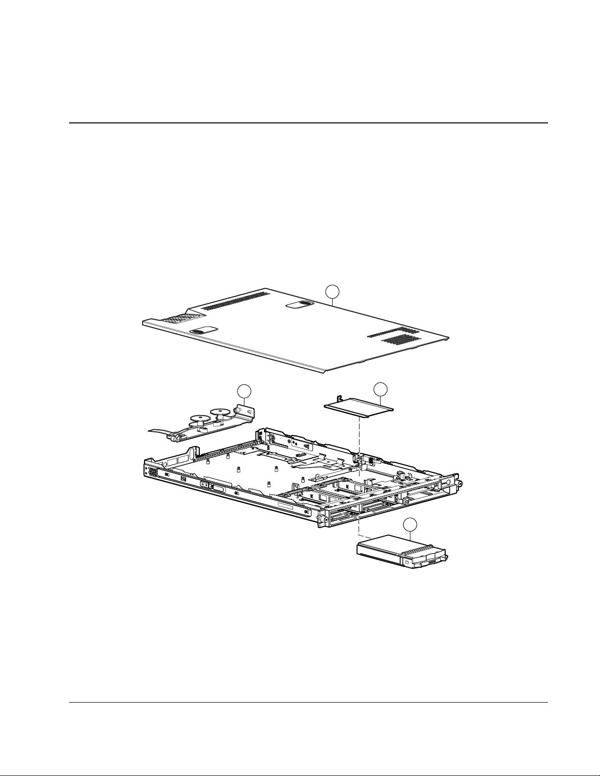
Mechanical Parts Exploded View
1
Illustrated Parts Catalog
1
19
Figure 1-1: Mechanical parts exploded view
18
2
Compaq ProLiant DL360 Generation 2 Server Maintenance and Service Guide 1-1
COMPAQ CONFIDENTIAL Codename: Maisto Part Number: 233831-001 Last Saved On: 11/19/01 9:08 AM
Page 9
Illustrated Parts Catalog
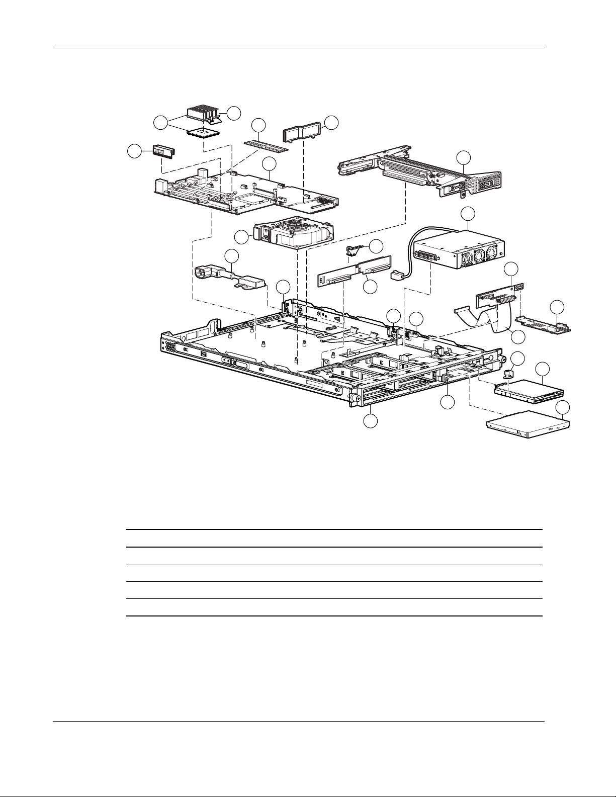
System Components Exploded View
15
16
17
5
14
7
4
23
22
Figure 1-2: System components exploded view
26
3
6
21
10
8
25
27
11
20
24
9
12
13
System and Mechanical Spare Parts List
Table 1-1: System and Mechanical Spare Parts List
Item Description Spare Part Number
Mechanical Components
1 Access Panel 252370-001
2 Hard Drive Blank 122759-001
3 PCI Riser Board Assembly 252356-001
1-2 Compaq ProLiant DL360 Generation 2 Server Maintenance and Service Guide
COMPAQ CONFIDENTIAL Codename: Maisto Part Number: 233831-001 Last Saved On: 11/19/01 9:08 AM
continued
Page 10

Illustrated Parts Catalog
Table 1-1: System and Mechanical Spare Parts List continued
Item Description Spare Part Number
System Components
4 Fan Assembly 252360-001
5 Filter, AC Power 252362-001
6 Power Supply 252361-001
Boards
7 System board (without processor; with two heatsinks -Not
shown)
8 SCSI backplane 173829-001
9 User Interface board 252358-001
10 CD-ROM drive and floppy diskette drive backplane 252357-001
Cable
11 CD-ROM/Diskette backplane to system board cable 252364-001
12
Mass Storage Devices
Low-profile 1.44MB diskette drive 252363-001
13 Low-profile IDE CD-ROM drive 228508-001
Memory
252355-001
14 128-MB registered 133-MHz SDRAM DIMM 159226-001
14 256-MB registered 133-MHz SDRAM DIMM 159377-001
14 512-MB registered 133-MHz SDRAM DIMM 159227-001
14 1-GB registered 133-MHz SDRAM DIMM 163902-001
Processors, PPM, and Heatsink
15 1.40 GHz Intel Pentium III processor with heatsink 252353-001
16 Processor power module (PPM) 237553-001
17 Heatsink 252354-001
Miscellaneous
Replacement System Board Battery 3-V lithium (Not shown) 234556-001
Country Kit (Not Shown) 252371-001
18
19
20
21
Hardware Kit
Cable protector
Fixed cable tray
Floppy retaining bracket with thumbscrew
SCSI backplane retaining clip with thumbscrew
252369-001
continued
Compaq ProLiant DL360 Generation 2 Server Maintenance and Service Guide 1-3
COMPAQ CONFIDENTIAL Codename: Maisto Part Number: 233831-001 Last Saved On: 11/19/01 9:08 AM
Page 11

Illustrated Parts Catalog
Table 1-1: System and Mechanical Spare Parts List continued
Item Description Spare Part Number
22
23
24
25
26
27
Return Kit 173842-001
Sliding Rails and Cable Management Solution 252366-001
Fixed Rail Kit 252365-001
Telco rack mounting kit 252367-001
AC “Y” power cord 178129-001
Power Supply, 200 W, -48V 254525-001
Low-profile DVD drive 269044-001
Plastic Kit
Air baffle
AC power connector cable retaining clip
CD ejection mechanism
Expansion board clip
Front Bezel
Power supply retaining clip
Option Kits (Not Shown)
252368-001
1-4 Compaq ProLiant DL360 Generation 2 Server Maintenance and Service Guide
COMPAQ CONFIDENTIAL Codename: Maisto Part Number: 233831-001 Last Saved On: 11/19/01 9:08 AM
Page 12

2
Removal and Replacement Procedures
This chapter provides subassembly/module-level removal and replacement procedures for
Compaq ProLiant DL360 Generation 2 servers. No tools are required to service the server.
After completing all necessary removal and replacement procedures, it is recommended that
server diagnostic programs be run to verify that all components are operating correctly.
TM
The following Diagnostic programs, from the SmartStart
used:
• Compaq System Configuration Utility
• Compaq Array Diagnostic Utility (ADU)
In addition the Compaq Server Diagnostics program may be run. This program is available
from the Compaq website at
www.compaq.com/support/files/server/us
and Support Software CD, may be
Electrostatic Discharge Information
A discharge of static electricity can damage static-sensitive devices or micro circuitry. Proper
packaging and grounding techniques are necessary precautions to prevent damage. To
prevent electrostatic damage, observe the following precautions:
• Transport products in static-safe containers such as conductive tubes, bags, or boxes.
• Keep electrostatic-sensitive parts in their containers until they arrive at static-free
stations.
• Cover workstations with approved static-dissipating material. Use a wrist strap connected
to the work surface and properly grounded tools and equipment.
• Keep the work area free of nonconductive materials such as ordinary plastic assembly
aids and foam packing.
• Always be properly grounded when touching a static-sensitive component or assembly.
• Avoid touching pins, leads, or circuitry.
• Always place drives PCB assembly-side down.
• Use conductive field service tools.
Compaq ProLiant DL360 Generation 2 Server Maintenance and Service Guide 2-1
COMPAQ CONFIDENTIAL Codename: Maisto Part Number: 233831-001 Last Saved On: 12/12/01 3:47 PM
Page 13

Removal and Replacement Procedures
Symbols on Equipment
Any product or assembly marked with these symbols indicates that the
component exceeds the recommended weight for one individual to handle safely.
25 kg
55 lb
CLASS 1 LASER PRODUCT
WARNING: To reduce the risk of personal injury or damage to the equipment,
observe local occupational health and safety requirements and guidelines for
manual material handling
Any surface or area of the equipment marked with these symbols indicates the
presence of a hot surface or hot component
WARNING: To reduce the risk of injury from a hot component, allow the surface
to cool before touching it.
To reduce the risk of injury from electric shock hazards, do not open this
enclosure.
WARNING: Any surface or area of the equipment marked with these symbols
indicates the presence of electric shock hazards. The enclosed area contains no
operator serviceable parts.
Any RJ-45 receptacle marked with these symbols indicates a Network Interface
Connection.
WARNING: To reduce the risk of electric shock, fire, or damage to the equipment,
do not plug telephone or telecommunications connectors into this receptacle.
This label or equivalent is located on the surface of your CD-ROM drive. This label
indicates that the product is classified as a Class 1 Laser Product.
2-2 Compaq ProLiant DL360 Generation 2 Server Maintenance and Service Guide
COMPAQ CONFIDENTIAL Codename: Maisto Part Number: 233831-001 Last Saved On: 12/12/01 3:47 PM
Page 14
Rack Warnings and Precautions
WARNING: To reduce the risk of personal injury or damage to equipment, always
ensure that the rack is adequately stabilized before extending a component outside the
rack. A rack may become unstable if more than one component is extended for any
reason. Extend only one component at a time.
WARNING: To reduce the risk of personal injury or damage to the equipment, be sure
that:
• The leveling jacks are extended to the floor.
• The full weight of the rack rests on the leveling jacks.
• The stabilizers are attached to the rack if it is a single rack installation.
• The racks are coupled together in multiple rack installations.
WARNING: When installing the server in a Telco rack, make certain that the rack frame
is adequately secured to the building structure at the top and bottom.
WARNING: To reduce the risk of personal injury or damage to the equipment, at least
two people are needed to safely unload the rack from the pallet. An empty 42U rack
weighs 253 lb (115 kg), is over 7 ft (2.1 m) tall, and may become unstable when being
moved on its casters. Do not stand in front of the rack as it rolls down the ramp from
the pallet, but handle the rack from both sides.
Removal and Replacement Procedures
Server Warnings and Precautions
WARNING: To reduce the risk of personal injury from hot surfaces, allow the hot-plug
drives and the internal system components to cool before touching.
WARNING: To reduce the risk of electric shock or damage to the equipment:
• Do not disable the power cord grounding plug. The grounding plug is an important
safety feature.
• Plug the power cord into a grounded (earthed) electrical outlet that is easily
accessible at all times.
• Unplug the power cord from each power supply to disconnect power to the
equipment.
CAUTION: Protect the server from power fluctuations and temporary interruptions with a
regulating uninterruptible power supply (UPS). This device protects the hardware from
damage caused by power surges and voltage spikes and keeps the system in operation
during a power failure.
CAUTION: The Compaq server must always be operated with the system access panel
closed. Proper cooling will not be achieved if the system access panel is removed.
Compaq ProLiant DL360 Generation 2 Server Maintenance and Service Guide 2-3
COMPAQ CONFIDENTIAL Codename: Maisto Part Number: 233831-001 Last Saved On: 12/12/01 3:47 PM
Page 15

Removal and Replacement Procedures
Preparation Procedures
Before removing any serviceable parts, determine whether the part is a hot-plug device or a
non-hot-plug device.
Hot-Plug Devices
The only hot-plug devices on Compaq ProLiant DL360 Generation 2 servers are the SCSI
hard drives. SCSI hard drives can be serviced without removing the server from the rack.
IMPORTANT: It is not necessary to turn off the server to replace hot-plug hard drives when they are
not in active use.
Non-Hot-Plug Devices
The CD-ROM drive can be replaced with the server power in standby mode. The CD-ROM
drive can be replaced without the need to remove the server from the rack.
To service all other non-hot plug devices, the server must be powered down completely by
removing the power cord. To service all other non-hot-plug devices the server must be
removed from the rack and the access panel removed after completely powering down the
server.
2-4 Compaq ProLiant DL360 Generation 2 Server Maintenance and Service Guide
COMPAQ CONFIDENTIAL Codename: Maisto Part Number: 233831-001 Last Saved On: 12/12/01 3:47 PM
Page 16
Powering Down the Server
System power in servers does not completely shut off with the front panel Power On/Standby
switch. The switch toggles between on and standby modes, rather than on and off. The
standby position removes power from most electronics and the drives, but portions of the
power supply and some internal circuitry remain active. To completely remove all power
from the system, disconnect all power cords from the server.
WARNING: To reduce the risk of injury from electric shock, remove the
power cord to completely disconnect power from the system.
WARNING: To reduce the risk of personal injury or damage to the equipment, ensure
that only one component is extended at a time. A rack may become unstable if more
than one component is extended for any reason.
WARNING: Because the rack allows you to stack computer components in a vertical
rather than a horizontal plane, you must take precautions to provide for rack stability
and safety to protect both personnel and property. Heed all cautions and warnings
throughout the installation instructions that came with the server.
WARNING: To reduce the risk of personal injury or damage to the equipment: If the
server is removed from the rack for device accessibility, remove the server from the
rack and place it on a sturdy table or workbench. Refer to the Compaq Setup and
Installation Guide for further information on working with racks.
CAUTION: The system power in the server does not completely shut off from the front
Power On/Standby switch. Moving the switch from on to standby leaves some portions of the
power supply and some internal circuitry active. Disconnect all power cords from the server to
remove all power from the system.
CAUTION: Electrostatic discharge may damage electronic components. Be sure you are
properly grounded before beginning any installation procedure. For more information, see
“Electrostatic Discharge Information” earlier in this chapter.
Removal and Replacement Procedures
Compaq ProLiant DL360 Generation 2 Server Maintenance and Service Guide 2-5
COMPAQ CONFIDENTIAL Codename: Maisto Part Number: 233831-001 Last Saved On: 12/12/01 3:47 PM
Page 17
Removal and Replacement Procedures
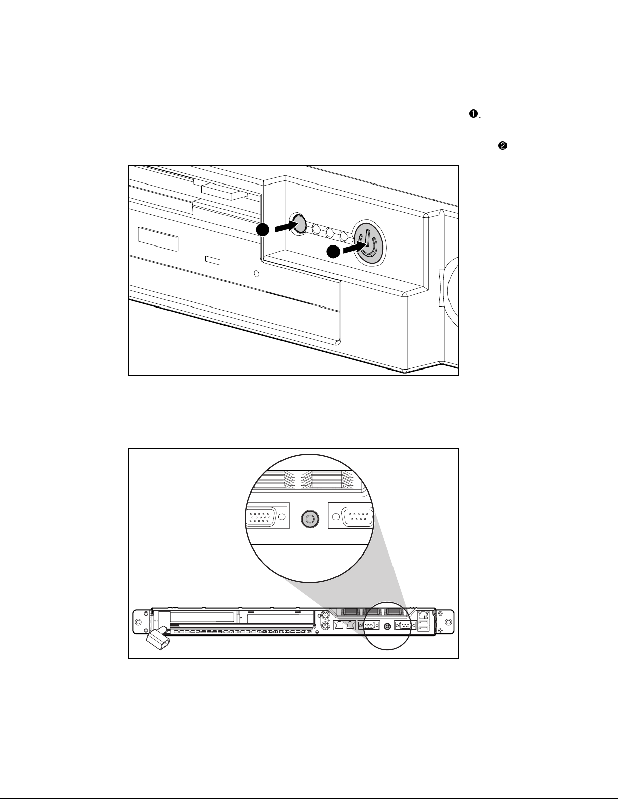
To power down the server:
1. Shut down the server operating system as directed by the operating system instructions.
2. Press the Front Unit Identification LED switch on the server front panel
Unit Identification LED switch illuminates.
3. Press the server Power On/Standby switch to place the server in standby mode
. The Rear
.
1
2
Figure 2-1: Front Unit Identification LED switch and Power
On/Standby switch
4. At the rear of the server, locate the illuminated Rear Unit Identification LED switch that
identifies the server being serviced.
Figure 2-2: Rear Unit Identification LED switch
5. Disconnect the power cord.
2-6 Compaq ProLiant DL360 Generation 2 Server Maintenance and Service Guide
COMPAQ CONFIDENTIAL Codename: Maisto Part Number: 233831-001 Last Saved On: 12/12/01 3:47 PM
Page 18
Removing the Server from the Rack
Depending on the rail option deployed on the server, perform one of the following:
• For the standard fixed rail deployment, disconnect all the peripherals cables and loosen
the thumbscrew that holds the fixed cable tray to the server. Extend and remove the
server from the rack. Place the server on a flat level workspace.
• For the Sliding Rails and Cable Management Solution, extend the server to its fullest
extent from the rack.
Reverse these procedures to replace the server into the rack.
Server Access Panel
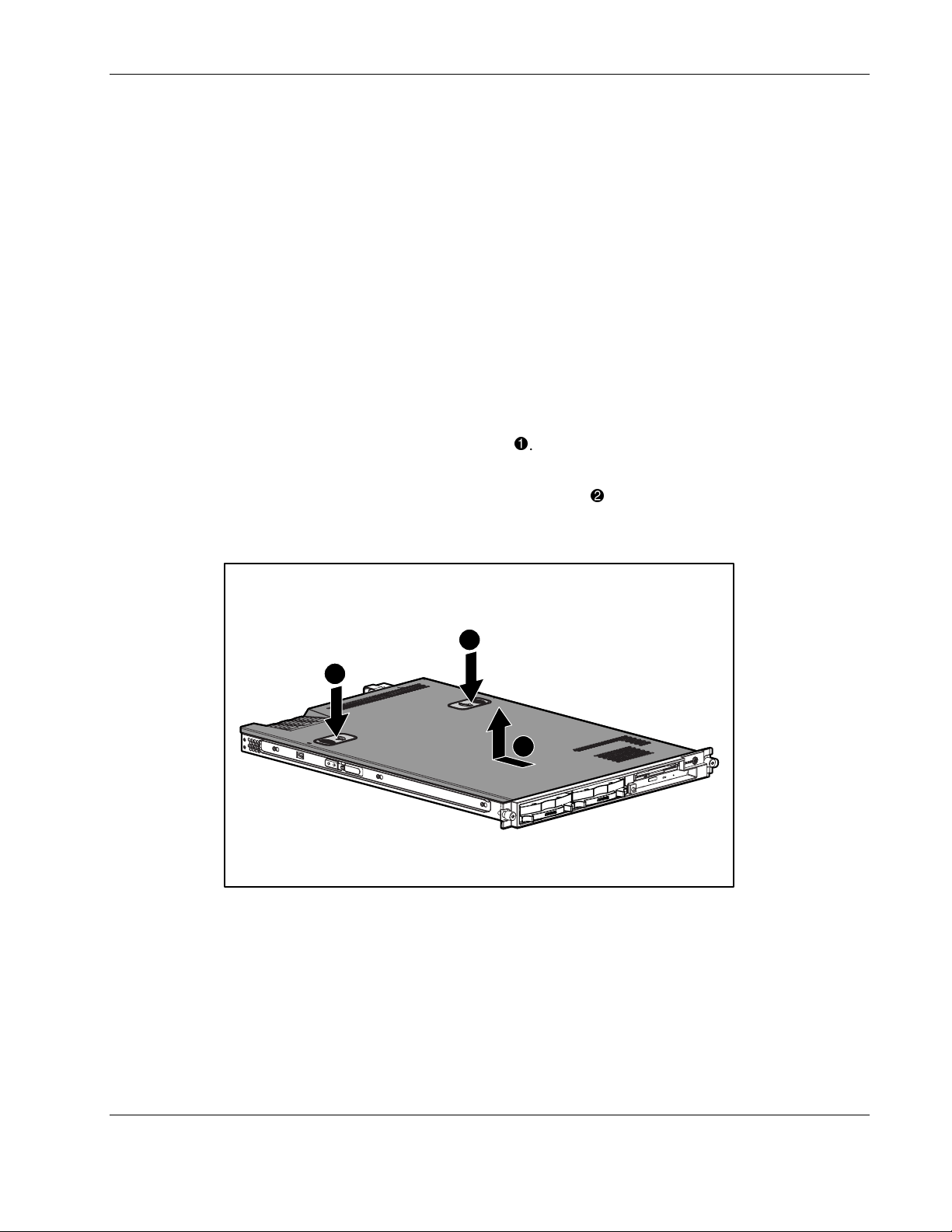
To remove the access panel:
Removal and Replacement Procedures
1. Press and hold down the hood latches
.
2. Holding the latches down, slide the access panel towards the rear of the server about
0.5 inch (1.25 cm) and lift the panel to remove it
.
The server is now ready for servicing.
1
1
2
Figure 2-3: Removing the access panel
Reverse steps 1 through 2 to replace the access panel.
Compaq ProLiant DL360 Generation 2 Server Maintenance and Service Guide 2-7
COMPAQ CONFIDENTIAL Codename: Maisto Part Number: 233831-001 Last Saved On: 12/12/01 3:47 PM
Page 19
Removal and Replacement Procedures
Mass Storage Devices
The Compaq ProLiant DL360 Generation 2 server supports up to four mass storage devices:
• Up to two 1-inch, hot-plug SCSI hard drives
• Low-profile CD-ROM drive
• Low-profile 3.5-inch, 1.44-MB diskette drive:
This section describes the drive cage positions and removal and replacement procedures for
these mass storage devices.
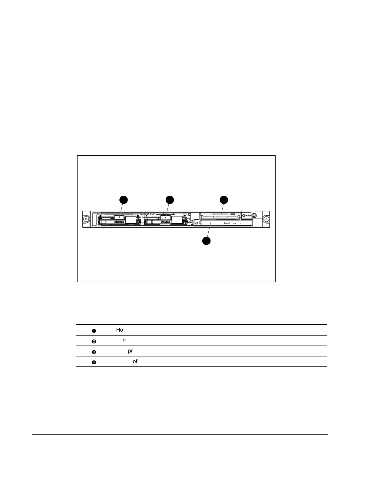
Drive Locations
1 2 3
4
Figure 2-4: Server drive positions
Table 2-1: Server Drive Locations
Location Drive SCSI ID
Hot-plug drive cage for a 1-inch height hot-plug SCSI hard drive 0
Hot-plug drive cage for a 1-inch height hot-plug SCSI hard drive 1
Low-profile 3.5-inch, 1.44 diskette drive -
Low-profile CD-ROM drive -
2-8 Compaq ProLiant DL360 Generation 2 Server Maintenance and Service Guide
COMPAQ CONFIDENTIAL Codename: Maisto Part Number: 233831-001 Last Saved On: 12/12/01 3:47 PM
Page 20
CD-ROM Drive
The server is delivered with a low-profile diskette drive and a low-profile CD-ROM drive.
The CD-ROM and the diskette drive may be removed independently of each other.
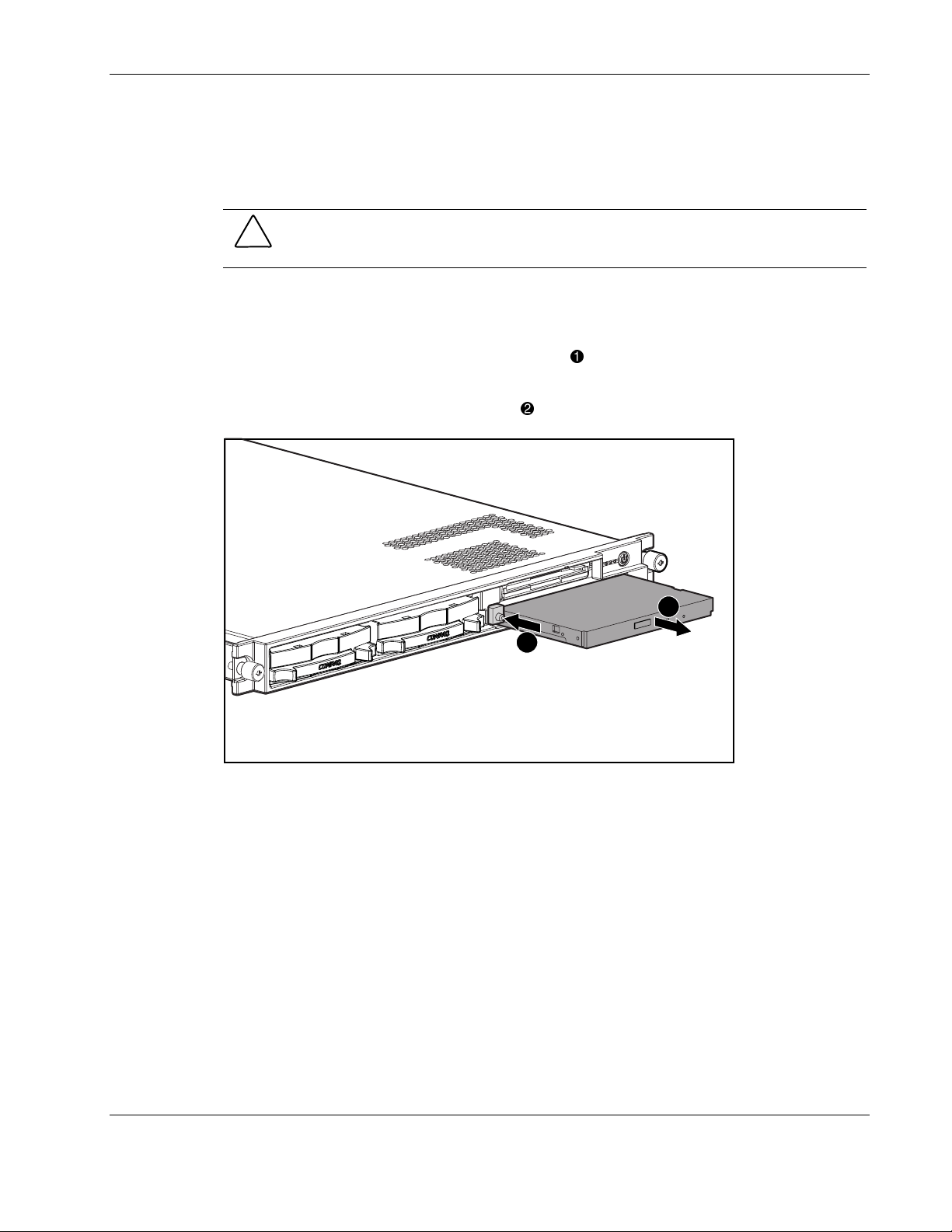
To remove the CD-ROM drive:
1. Press the Power On/Standby switch to place the server in standby mode.
2. Push the center of the dual action eject button
push the square body of the button to push the CD-ROM drive forward out of the chassis.
Removal and Replacement Procedures
CAUTION: Do not operate the server without a CD-ROM drive installed. Failure to install a
CD-ROM can lead to improper cooling and may damage the system.
to release the locking latch. Continue to
3. Remove the CD-ROM from the server
Figure 2-5: Removing the CD-ROM drive
.
2
1
Compaq ProLiant DL360 Generation 2 Server Maintenance and Service Guide 2-9
COMPAQ CONFIDENTIAL Codename: Maisto Part Number: 233831-001 Last Saved On: 12/12/01 3:47 PM
Page 21
Removal and Replacement Procedures
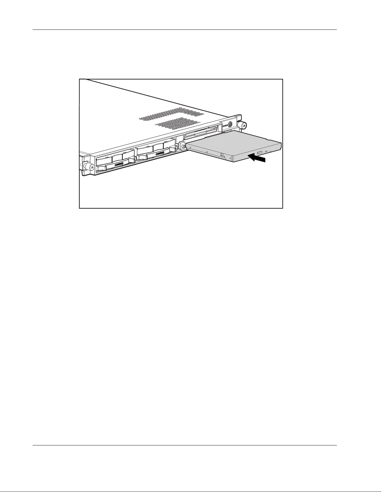
To replace the CD-ROM drive:
1. Align the CD-ROM with the empty bay and slide the assembly into the chassis until it is
fully seated.
Figure 2-6: Aligning and installing the CD-ROM drive
2. Press the Power/On Standby switch to power on the server, and resume normal
operations.
2-10 Compaq ProLiant DL360 Generation 2 Server Maintenance and Service Guide
COMPAQ CONFIDENTIAL Codename: Maisto Part Number: 233831-001 Last Saved On: 12/12/01 3:47 PM
Page 22

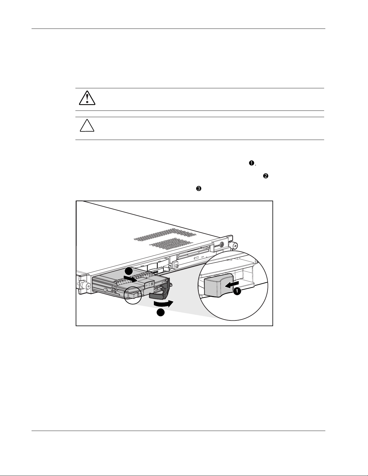
Low Profile Diskette Drive
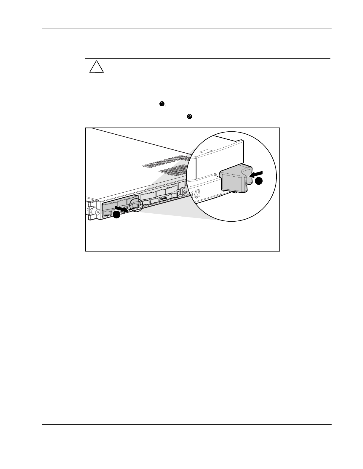
To remove the diskette (floppy) drive:
CAUTION: Do not operate the server without a diskette drive installed. Failure to install a
diskette drive can lead to improper cooling and may damage the system.
1. Power down the server. See “Powering Down the Server” in this chapter.
2. Remove the server from the rack. See “Removing the Server from the Rack” in this
chapter.
3. Remove the access panel. See “Server Access Panel” in this chapter.
4. To remove the diskette drive locking tab, turn the thumbscrew counterclockwise and
remove the tab
.
Removal and Replacement Procedures
5. Push the diskette drive from the rear to release it from the backplane connector
pull the drive forward out of the chassis
3
.
1
2
Figure 2-7: Removing the diskette drive.
and
Compaq ProLiant DL360 Generation 2 Server Maintenance and Service Guide 2-11
COMPAQ CONFIDENTIAL Codename: Maisto Part Number: 233831-001 Last Saved On: 12/12/01 3:47 PM
Page 23

Removal and Replacement Procedures
To replace the diskette drive:
1. Insert the diskette drive through the opening in the front panel
.
2. Align the connectors on the backplane and the rear of the diskette drive and push them
together
.
3. Replace the diskette drive locking tab and turn the thumbscrew clockwise to secure the
drive
.
1
3
2
Figure 2-8: Installing the diskette drive.
4. Replace the access panel. See “Server Access Panel” in this chapter.
5. Replace the server in the rack. See “Removing the server from the Rack” in this chapter.
6. Connect the power cord.
7. Press the Power On/Standby switch to power on the server and resume normal
operations.
2-12 Compaq ProLiant DL360 Generation 2 Server Maintenance and Service Guide
COMPAQ CONFIDENTIAL Codename: Maisto Part Number: 233831-001 Last Saved On: 12/12/01 3:47 PM
Page 24
Hot-Plug SCSI Hard Drive Blank
CAUTION: Do not operate the server without a SCSI hard drive or a SCSI hard drive blank
installed. Failure to install a SCSI hard drive or a SCSI hard drive blank can lead to improper
cooling and may damage the system.
To remove a hot-plug SCSI hard drive blank:
Removal and Replacement Procedures
1. Press the release button
2. Pull the blank out of the drive bay
2
.
.
1
Figure 2-9: Removing a hard drive blank
To replace the blank, slide the blank into the bay until it clicks, locking into place.
Compaq ProLiant DL360 Generation 2 Server Maintenance and Service Guide 2-13
COMPAQ CONFIDENTIAL Codename: Maisto Part Number: 233831-001 Last Saved On: 12/12/01 3:47 PM
Page 25
Removal and Replacement Procedures
Hot-Plug SCSI Hard Drives
To assess a hard drive’s status, you must observe and understand the hot-plug SCSI hard
drive status LEDs. For a detailed explanation of hard drive status LEDs, see Chapter 5,
“Connectors, Switches, Jumpers and Status LED Indicators.”
WARNING: Read “Hot-plug Hard Drive Replacement Guidelines” in the Compaq
Servers Troubleshooting Guide prior to removing a hard drive.
CAUTION: Do not operate the server without a SCSI hard drive or a SCSI hard drive blank
installed. Failure to install a SCSI hard drive or a SCSI hard drive blank can lead to improper
cooling and may damage the system.
To remove a hot-plug SCSI hard drive:
1. Press the release button to unlock the lever on the hard drive
.
2. Pull the ejector lever to release the SCSI hard drive from the cage
3. Pull the drive to remove it from the cage
3
2
Figure 2-10: Removing a hot-plug SCSI hard drive
.
1
.
2-14 Compaq ProLiant DL360 Generation 2 Server Maintenance and Service Guide
COMPAQ CONFIDENTIAL Codename: Maisto Part Number: 233831-001 Last Saved On: 12/12/01 3:47 PM
Page 26

To replace the hard drive:
Removal and Replacement Procedures
1. Slide the drive into the cage until it clicks
2. Close the lever to lock the drive in place
1
.
.
2
Figure 2-11: Installing a hot-plug SCSI hard drive
Compaq ProLiant DL360 Generation 2 Server Maintenance and Service Guide 2-15
COMPAQ CONFIDENTIAL Codename: Maisto Part Number: 233831-001 Last Saved On: 12/12/01 3:47 PM
Page 27

Removal and Replacement Procedures
SCSI Backplane
To remove the SCSI backplane:
1. Power down the server. See “Powering Down the Server” earlier in this chapter.
2. Remove the server from the rack. See “Removing the Server from the Rack” in this
chapter.
3. Remove the access panel. See “Server Access Panel” in this chapter.
4. Remove the hot-plug SCSI hard drives. See “Hot-Plug SCSI Hard Drives” earlier in this
chapter.
5. Loosen the system board thumbscrew
secures the SCSI backplane to the system board.
and remove the thumbscrew assembly that
2
1
Figure 2-12: Removing the system board thumbscrew assembly
2-16 Compaq ProLiant DL360 Generation 2 Server Maintenance and Service Guide
COMPAQ CONFIDENTIAL Codename: Maisto Part Number: 233831-001 Last Saved On: 12/12/01 3:47 PM
Page 28

Removal and Replacement Procedures
6. Carefully pull back and hold the plastic retaining clip .
7. Remove the SCSI backplane by lifting it straight up from system board until it disengages
from the system board connector.
2
1
Figure 2-13: Removing the SCSI backplane
Reverse steps 1 through 7 to replace the SCSI backplane.
Compaq ProLiant DL360 Generation 2 Server Maintenance and Service Guide 2-17
COMPAQ CONFIDENTIAL Codename: Maisto Part Number: 233831-001 Last Saved On: 12/12/01 3:47 PM
Page 29

Removal and Replacement Procedures
PCI Riser Board Assembly
To remove the PCI riser board assembly:
1. Power down the server. See “Powering Down the Server” earlier in this chapter.
2. Remove the server from the rack. See “Removing the Server from the Rack” in this
chapter.
3. Remove the access panel. See “Server Access Panel” earlier in this chapter.
4. Disconnect any cables leading from any current expansion boards to the system board.
5. Lift the expansion board retaining lever.
Figure 2-14: Lifting the expansion board retaining lever (expansion
boards removed for clarity)
2-18 Compaq ProLiant DL360 Generation 2 Server Maintenance and Service Guide
COMPAQ CONFIDENTIAL Codename: Maisto Part Number: 233831-001 Last Saved On: 12/12/01 3:47 PM
Page 30

Removal and Replacement Procedures
6. Unlock the PCI riser board assembly by disengaging the locking latch .
7. Lift the PCI riser board assembly ejector
.
8. Slide the assembly toward the outside edge of the server to release the assembly from the
server chassis
9. Lift the assembly from the server chassis
.
.
4
4
3
2
1
Figure 2-15: Removing the PCI riser board assembly (expansion
boards removed for clarity)
Reverse steps 1 through 9 to replace the PCI riser board assembly.
Compaq ProLiant DL360 Generation 2 Server Maintenance and Service Guide 2-19
COMPAQ CONFIDENTIAL Codename: Maisto Part Number: 233831-001 Last Saved On: 12/12/01 3:47 PM
Page 31

Removal and Replacement Procedures
Expansion Board Slot 1
To remove an expansion board from slot 1:
1. Power down the server. See “Powering Down the Server” earlier in this chapter.
2. Remove the server from the rack. See “Removing the Server from the Rack” in this
chapter.
3. Remove the access panel. See “Server Access Panel” earlier in this chapter.
4. Remove the PCI riser board assembly. See “PCI Riser Board Assembly” in this chapter.
5. Slide the expansion board retaining clip out from the assembly
.
6. Slide the expansion board out of the expansion slot
2
.
1
Figure 2-16: Removing an expansion board from slot 1
CAUTION: Always ensure that an expansion board or expansion slot cover is installed before
powering up and operating the server. Failure to install either an expansion board or
expansion slot cover can lead to improper cooling and may damage the system.
Reverse steps 1 through 6 to replace the expansion board in the expansion slot. Be sure that
the expansion board slides into the guiding groove, aligning with the slot.
2-20 Compaq ProLiant DL360 Generation 2 Server Maintenance and Service Guide
COMPAQ CONFIDENTIAL Codename: Maisto Part Number: 233831-001 Last Saved On: 12/12/01 3:47 PM
Page 32

Expansion Board Slot 2
To remove an expansion board in slot 2:
1. Power down the server. See “Powering Down the Server” earlier in this chapter.
2. Remove the server from the rack. See “Removing the Server from the Rack” in this
chapter.
3. Remove the access panel. See “Server Access Panel” earlier in this chapter.
4. Remove the PCI riser board assembly. See “PCI Riser Board Assembly” earlier in this
chapter.
5. Slide the expansion board out of the expansion slot.
Removal and Replacement Procedures
Figure 2-17: Removing an expansion board from slot 2
CAUTION: Always ensure that an expansion board or expansion slot cover is installed before
powering up and operating the server. Failure to install either an expansion board or
expansion slot cover can lead to improper cooling and may damage the system.
Reverse steps 1 through 5 to install an expansion board into slot 2.
Compaq ProLiant DL360 Generation 2 Server Maintenance and Service Guide 2-21
COMPAQ CONFIDENTIAL Codename: Maisto Part Number: 233831-001 Last Saved On: 12/12/01 3:47 PM
Page 33

Removal and Replacement Procedures
Air Baffle
To remove the air baffle:
1. Power down the server. See “Powering Down the Server” earlier in this chapter.
2. Remove the server from the rack. See “Removing the Server from the Rack” in this
chapter.
3. Remove the access panel. See “Server Access Panel” earlier in this chapter.
4. Remove the PCI riser board assembly. See “PCI Riser Board Assembly” in this chapter.
CAUTION: Always remove the PCI riser board assembly before removing the air baffle.
Failure to remove the assembly may result in damage to expansion boards.
5. Remove the air baffle by lifting it straight up from the system board.
Figure 2-18: Removing the air baffle
Reverse steps 1 through 5 to replace the air baffle.
2-22 Compaq ProLiant DL360 Generation 2 Server Maintenance and Service Guide
COMPAQ CONFIDENTIAL Codename: Maisto Part Number: 233831-001 Last Saved On: 12/12/01 3:47 PM
Page 34

Fan Assembly
To remove the fan assembly:
1. Power down the server. See “Powering Down the Server” earlier in this chapter.
2. Remove the server from the rack. See “Removing the Server from the Rack” in this
chapter.
3. Remove the access panel. See “Server Access Panel” earlier in this chapter.
4. Remove the PCI riser board assembly. See “PCI Riser Board Assembly” in this chapter.
5. Remove the air baffle. See “Air Baffle” earlier in this chapter.
6. Press in the retaining clips on either side of the fan assembly
from the chassis
Removal and Replacement Procedures
and lift the assembly
.
2
1
1
Figure 2-19: Removing the fan assembly
Reverse steps 1 through 6 to replace the fan assembly, ensuring that the retaining clips lock
into place.
Compaq ProLiant DL360 Generation 2 Server Maintenance and Service Guide 2-23
COMPAQ CONFIDENTIAL Codename: Maisto Part Number: 233831-001 Last Saved On: 12/12/01 3:47 PM
Page 35

Removal and Replacement Procedures
AC Power Cord and Line Filter
To remove the AC power cord and line filter:
1. Power down the server. See “Powering Down the Server” in this chapter.
2. Remove the server from the rack. See “Removing the Server from the Rack” in this
chapter.
3. Remove the access panel. See “Server Access Panel” earlier in this chapter.
4. Remove the PCI riser board assembly. See “PCI Riser Board Assembly” in this chapter.
5. Using a finger, lift the line filter off the chassis retaining stud and release the line filter
from the chassis mount
6. Slide the power cord retaining clip
2
.
upward to free the AC power cord.
1
Figure 2-20: Releasing the AC power cord and line filter
7. Lift the AC power cord and filter free of the server chassis.
2-24 Compaq ProLiant DL360 Generation 2 Server Maintenance and Service Guide
COMPAQ CONFIDENTIAL Codename: Maisto Part Number: 233831-001 Last Saved On: 12/12/01 3:47 PM
Page 36

Removal and Replacement Procedures
8. Loosen the retaining clip screw , with a screwdriver, and slide the retaining clip clear of
the release latch
.
1
2
Figure 2-21: Sliding off the retaining clip
9. Press the release latch and pull the filter to disconnect the power cord and line filter
assembly from the server internal power cord
.
2
1
2
Figure 2-22: Disconnecting the line filter from the server
internal power cord
Reverse steps 1 through 9 to replace the AC power cord and filter.
Compaq ProLiant DL360 Generation 2 Server Maintenance and Service Guide 2-25
COMPAQ CONFIDENTIAL Codename: Maisto Part Number: 233831-001 Last Saved On: 12/12/01 3:47 PM
Page 37

Removal and Replacement Procedures
Power Supply
To remove the power supply:
1. Power down the server. See “Powering Down the Server” in this chapter.
2. Remove the server from the rack. See “Removing the Server from the Rack” in this
chapter.
3. Remove the access panel. See “Server Access Panel” in this chapter.
4. Remove the PCI riser board assembly. See “PCI Riser Board Assembly” in this chapter.
5. Remove the air baffle. See “Air Baffle” in this chapter.
6. Remove the AC power cord and filter. See “AC Power Cord and Filter” in this chapter.
7. Release the AC power cord from its routing clips.
8. Lift the power supply retaining latch
9. Slide the power supply toward the outside edge of the server until it disengages from the
system board connector
.
.
10. Tilt the outside edge of the power supply upward and lift to remove it from the chassis
3
1
2
Figure 2-23: Removing the power supply
Reverse steps 1 through 10 to replace the power supply, aligning the pins with the system
board connector when inserting the power supply.
.
2-26 Compaq ProLiant DL360 Generation 2 Server Maintenance and Service Guide
COMPAQ CONFIDENTIAL Codename: Maisto Part Number: 233831-001 Last Saved On: 12/12/01 3:47 PM
Page 38

Cable Protector
To remove the cable protector:
1. Complete the preparation procedures. See “Powering Down the Server” in this chapter.
2. Remove the server from the rack. See “Removing the Server from the Rack” in this
chapter.
3. Remove the access panel. See “Server Access Panel” in this chapter.
4. Remove the PCI riser board assembly. See “PCI Riser Board Assembly” in this chapter.
5. Remove the air baffle. See “Air Baffle” in this chapter.
6. Remove the AC power cord and filter. See “AC Power Cord and Filter” in this chapter.
7. Remove the power supply. See “Power Supply” in this chapter.
8. Lift the front edge of the cable protector until it clears the CD ROM/Diskette backplane.
9. Pull the cable protector forward until it is free from its retaining slots. Lift the cable
protector from the server.
Removal and Replacement Procedures
1
Figure 2-24: Removing the cable protector
Retaining slots
Reverse steps 1 through 9 to replace the cable protector.
Compaq ProLiant DL360 Generation 2 Server Maintenance and Service Guide 2-27
COMPAQ CONFIDENTIAL Codename: Maisto Part Number: 233831-001 Last Saved On: 12/12/01 3:47 PM
Page 39

Removal and Replacement Procedures
CD-ROM and Diskette Drive Cable and Backplane
To remove the CD-ROM and diskette drive cable and backplane:
1. Power down the server. See “Powering Down the Server” in this chapter.
2. Remove the server from the rack. See “Removing the server from the Rack” in this
chapter.
3. Remove the access panel. See “Server Access Panel” in this chapter.
4. Remove the CD-ROM and diskette drives. See “Replacing the CD-ROM Drive” and
“Replacing the Floppy Drive” in this chapter for removal procedures.
5. Remove the PCI riser board assembly. See “PCI Riser Board Assembly” in this chapter.
6. Remove the air baffle. See “Air Baffle” in this chapter.
7. Remove the AC power cord and line filter. See “AC Power Cord and Line Filter” in this
chapter.
8. Remove the power supply. See “Power Supply” in this chapter.
9. Remove the cable protector. See “Cable Protector” in this chapter.
10. Disconnect the 80-pin connector from the system board.
Figure 2-25: Disconnecting the 80-pin connector from the system
board
2-28 Compaq ProLiant DL360 Generation 2 Server Maintenance and Service Guide
COMPAQ CONFIDENTIAL Codename: Maisto Part Number: 233831-001 Last Saved On: 12/12/01 3:47 PM
Page 40

Removal and Replacement Procedures
11. Slide the cable from underneath the routing sleeve . Refer to Chapter 3 for the cable
routing diagram.
12. Carefully pull back and hold the plastic retaining clip
.
13. Lift the backplane vertically until it disconnects from the user interface board and clears
the guiding grooves
.
1
3
2
Figure 2-26: Removing CD-ROM and diskette drive cable and
backplane from the chassis
Reverse steps 1 through 13 to replace the CD-ROM and diskette drive cable and backplane.
Compaq ProLiant DL360 Generation 2 Server Maintenance and Service Guide 2-29
COMPAQ CONFIDENTIAL Codename: Maisto Part Number: 233831-001 Last Saved On: 12/12/01 3:47 PM
Page 41

Removal and Replacement Procedures
User Interface Board
To remove the user interface board:
1. Power down the server. See “Powering Down the Server” in this chapter.
2. Remove the server from the rack. See “Removing the Server from the Rack” in this
chapter.
3. Remove the access panel. See “Server Access Panel” in this chapter.
4. Remove the CD-ROM and diskette drives. See “Replacing the CD-ROM Drive” and
“Replacing the Floppy Drive” in this chapter for removal procedures.
5. Remove the PCI riser board assembly. See “PCI Riser Board Assembly” in this chapter.
6. Remove the air baffle. See “Air Baffle” in this chapter.
7. Remove the AC power cord and filter. See “AC Power Cord and Filter” in this chapter.
8. Remove the power supply. See “Power Supply” in this chapter.
9. Remove the cable protector. See “Cable Protector” earlier in this chapter.
10. Remove the CD-ROM and diskette drive backplane. See “CD-ROM and Diskette Drive
Backplane” earlier in this chapter.
11. Slide the user interface board toward the rear of the server and lift to remove.
Figure 2-27: Removing the user interface board
Reverse steps 1 through 11 to replace the user interface board.
2-30 Compaq ProLiant DL360 Generation 2 Server Maintenance and Service Guide
COMPAQ CONFIDENTIAL Codename: Maisto Part Number: 233831-001 Last Saved On: 12/12/01 3:47 PM
Page 42

Memory
Removal and Replacement Procedures
The ProLiant DL360 Generation 2 server ships standard with two 128-MB Synchronous
DRAM (SDRAM) Dual Inline Memory Modules (DIMMs) installed in DIMM sockets 1 and
2 (Bank A).
Observe the following guidelines when installing additional memory:
• SDRAM DIMMs must be 133-MHz, registered, 3.3-volt, 72-bit wide, with Error
Correction Code (ECC). No other DIMMS are compatible with the server.
• Use only 128-, 256-, 512-MB, or 1-GB SDRAM DIMMs. DIMMs must be installed in
pairs and be of the same size.
• Install DIMMs only in one direction. Be sure to match the notch on the module with the
tab on the DIMM slot. Before seating the DIMM in the slot, ensure that the module key is
fully inserted.
• Memory can be expanded to a maximum of 4-GB of memory.
• Use only Compaq SDRAM DIMMs. DIMMs from other sources may affect data
integrity.
• Install SDRAM DIMM modules one at a time in the sequential order starting with DIMM
socket 1.
Compaq ProLiant DL360 Generation 2 Server Maintenance and Service Guide 2-31
COMPAQ CONFIDENTIAL Codename: Maisto Part Number: 233831-001 Last Saved On: 12/12/01 3:47 PM
Page 43

Removal and Replacement Procedures
SDRAM DIMMs
The Compaq ProLiant DL360 Generation 2 server ships standard with two SDRAM DIMMs
installed in DIMM sockets 1 and 2 (Bank A). The following figure and table show the
location of the DIMM slots on the system board.
1 2 3 4
Figure 2-28: DIMM sockets identified on the system board
Table 2-2: DIMM Socket Identification
Item Description
DIMM socket 1A populated with standard 128-MB DIMM
DIMM socket 2A populated with standard 128-MB DIMM
DIMM socket 3B
DIMM socket 4B
CAUTION: Electrostatic discharge may damage electronic components. Be sure you are
properly grounded before beginning any installation procedure. See “Electrostatic Discharge
Information” earlier in this chapter.
2-32 Compaq ProLiant DL360 Generation 2 Server Maintenance and Service Guide
COMPAQ CONFIDENTIAL Codename: Maisto Part Number: 233831-001 Last Saved On: 12/12/01 3:47 PM
Page 44

Removal and Replacement Procedures
To remove a SDRAM DIMM:
1. Power down the server. See “Powering Down the Server” in this chapter.
2. Remove the server from the rack. See “Removing the Server from the Rack” in this
chapter.
3. Remove the access panel. See “Server Access Panel” in this chapter.
4. Press both SDRAM DIMM slot latches outward
5. Lift the SDRAM DIMM from the socket
.
.
2
1
1
Figure 2-29: Removing an SDRAM DIMM
Reverse steps 1 through 5 to replace a SDRAM DIMM.
IMPORTANT: A memory module can be installed only one way. Be sure to match the key slots on the
module with the tabs on the memory slot. Push the module down into the slot, ensuring that the module
is fully inserted and properly seated.
IMPORTANT: DIMMs must be installed in pairs and be of the same size.
IMPORTANT: DIMMs must be 133-MHz registered SDRAM, 3.3-volts, 72-bits wide, and ECC.
Compaq ProLiant DL360 Generation 2 Server Maintenance and Service Guide 2-33
COMPAQ CONFIDENTIAL Codename: Maisto Part Number: 233831-001 Last Saved On: 12/12/01 3:47 PM
Page 45

Removal and Replacement Procedures
Processors
The server can support up to two processors. Each processor has an associated Processor
Power Module (PPM) that must be present for proper operation of the server.
Figure 2-30 and Table 2-3 show the location of the processors and PPMs on the system
board.
21
3
4
Figure 2-30: Processor and PPM socket locations
Table 2-3: Processor and PPM Sockets
Item Description
Note: A PPM must be installed with a processor.
PPM socket 1 (must always be populated)
Processor socket 1 (must always be populated)
Processor socket 2
PPM socket 2
WARNING: To reduce the risk of personal injury from hot surfaces, allow the internal
system components to cool before touching.
CAUTION: Processor socket 1 must be populated at all times. Failure to follow this process
results in the system failing to boot and halting during the POST. This error will result in the
system not functioning properly.
2-34 Compaq ProLiant DL360 Generation 2 Server Maintenance and Service Guide
COMPAQ CONFIDENTIAL Codename: Maisto Part Number: 233831-001 Last Saved On: 12/12/01 3:47 PM
Page 46

Removal and Replacement Procedures
To remove a processor:
1. Power down the server. See “Powering Down the Server” in this chapter.
2. Remove the server from the rack. See “Removing the Server from the Rack” in this
chapter.
3. Remove the access panel. See “Server Access Panel” in this chapter.
4. Push down on the integrated heatsink-retaining clip
tab on the processor socket
.
and release it from the retaining
5. Remove the heatsink and integrated thermal pad from the processor
6. Lift the processor locking lever
7. Lift the processor from the socket
3
5
.
.
1
2
.
4
Figure 2-31: Removing the processor
Compaq ProLiant DL360 Generation 2 Server Maintenance and Service Guide 2-35
COMPAQ CONFIDENTIAL Codename: Maisto Part Number: 233831-001 Last Saved On: 12/12/01 3:47 PM
Page 47

Removal and Replacement Procedures
CAUTION: Always use a new thermal pad and heatsink when replacing processors. Failure
to use new components may result in damage to the processor.
CAUTION: Heatsinks have an integrated, plastic-covered thermal pad. Remove the plastic
cover from the new heatsink to expose the adhesive side of the thermal pad before placing
the heatsink on the processor.
Reverse steps 1 through 7 to replace the processor.
2-36 Compaq ProLiant DL360 Generation 2 Server Maintenance and Service Guide
COMPAQ CONFIDENTIAL Codename: Maisto Part Number: 233831-001 Last Saved On: 12/12/01 3:47 PM
Page 48

Processor Power Module
Each processor has an associated Processor Power Module (PPM). Figure 2-30 and Table 2-3
show the location of the processors and PPMs on the system board.
To remove a PPM:
1. Power down the server. See “Powering Down the Server” in this chapter.
2. Remove the server from the rack. See “Removing the Server from the Rack” in this
chapter.
3. Remove the access panel. See “Server Access Panel” in this chapter.
Removal and Replacement Procedures
4. Open the PPM socket latches
5. Lift the PPM from the socket
1
Figure 2-32: Removing a PPM
.
.
2
Repeat steps 1 through 5 to replace a PPM.
1
Compaq ProLiant DL360 Generation 2 Server Maintenance and Service Guide 2-37
COMPAQ CONFIDENTIAL Codename: Maisto Part Number: 233831-001 Last Saved On: 12/12/01 3:47 PM
Page 49

Removal and Replacement Procedures
Battery
If the server no longer automatically displays the correct date and time, it may be necessary to
replace the battery that provides power to the real-time clock. Under normal use, battery life
is 5 to 10 years.
WARNING: This server contains either an internal lithium manganese dioxide, or a
vanadium pentoxide battery. There is risk of fire and burns if the battery pack is not
handled properly. To reduce the risk of personal injury:
• Do not attempt to recharge the battery.
• Do not expose to temperatures higher than 60°C.
• Do not disassemble, crush, puncture, short external contacts, or dispose of in fire
or water.
• Replace only with the spare designated for this product.
CAUTION: Loss of BIOS settings will occur if the lithium battery is removed. BIOS settings
must be reconfigured whenever the battery is replaced.
CAUTION: Batteries, battery packs, and accumulators should not be disposed of
along with general household waste. In order to forward them for recycling or proper
disposal, please use the public collection system, or return them to your authorized
Partners or their agents.
IMPORTANT: Run the System Utility to configure the system after replacing the battery. See
Chapter 4, “Diagnostic Tools” for more information.
2-38 Compaq ProLiant DL360 Generation 2 Server Maintenance and Service Guide
COMPAQ CONFIDENTIAL Codename: Maisto Part Number: 233831-001 Last Saved On: 12/12/01 3:47 PM
Page 50

Removal and Replacement Procedures
To remove the system board battery:
1. Power down the server. See “Powering Down the Server” in this chapter.
2. Remove the server from the rack. See “Removing the Server from the Rack” in this
chapter.
3. Remove the access panel. See “Server Access Panel” in this chapter.
4. Locate the battery holder on the system board
.
Figure 2-33: Battery location
5. Push the battery security clip away from the center of the holder and remove the
battery
Figure 2-34: Removing the battery
.
2
1
Reverse steps 1 through 5 to replace the battery.
Compaq ProLiant DL360 Generation 2 Server Maintenance and Service Guide 2-39
COMPAQ CONFIDENTIAL Codename: Maisto Part Number: 233831-001 Last Saved On: 12/12/01 3:47 PM
Page 51

Removal and Replacement Procedures
System Board
To remove the system board:
1. Power down the server. See “Powering Down the Server” in this chapter.
2. Remove the server from the rack. See “Removing the Server from the Rack” in this
chapter.
3. Remove the access panel. See “Server Access Panel” in this chapter.
4. Remove the hot-plug SCSI hard drive(s). See “Hot-Plug SCSI Hard Drives” in this
chapter.
5. Remove the SCSI backplane. See “SCSI Backplane” in this chapter.
6. Remove the PCI riser board assembly. See “PCI Riser Board Assembly” in this chapter.
7. Remove the air baffle. See “Air Baffle” in this chapter.
8. Remove the fan assembly. See “Fan Assembly” in this chapter.
9. Remove the AC power cord and filter. See “AC Power Cord and Filter” in this chapter.
10. Remove the power supply. See “Power Supply” in this chapter.
11. Disconnect the 80-pin connector from the system board. See “CD-ROM and Diskette
Drive Cable and Backplane” in this chapter.
12. Remove any SDRAM DIMMs. See “SDRAM DIMMs” in this chapter.
13. Remove the processor(s). See “Processors” in this chapter.
14. Remove the PPM(s). See “Processor Power Module” in this chapter.
15. Locate the alignment keys and keyhole locations
1
2
3
4
through on the system board.
5
6
7
8
9
Figure 2-35: Locating alignment keys and keyhole locations
2-40 Compaq ProLiant DL360 Generation 2 Server Maintenance and Service Guide
COMPAQ CONFIDENTIAL Codename: Maisto Part Number: 233831-001 Last Saved On: 12/12/01 3:47 PM
Page 52

Removal and Replacement Procedures
16. Slide the system board toward the front of the chassis 0.5 inch (1.5 cm) , ensuring that
the board unseats from all the alignment keys.
17. Tilt the front edge of the system board upward and lift it off the alignment keys
.
1
2
Figure 2-36: Removing the system board
CAUTION: Always use a new heatsink with integrated thermal pad when replacing
processors. Failure to use new components may result in damage to the processor.
Reverse steps 1 through 17 to replace the system board. When reinstalling the processors on
the new system board, discard used heatsinks and thermal pads. Reinstall the processors with
new heatsinks and integrated thermal pads that come in the system board spare parts kit. For
more information, see “Processors” earlier in this chapter.
Compaq ProLiant DL360 Generation 2 Server Maintenance and Service Guide 2-41
COMPAQ CONFIDENTIAL Codename: Maisto Part Number: 233831-001 Last Saved On: 12/12/01 3:47 PM
Page 53

Cable Routing Diagram
The Compaq ProLiant DL360 Generation 2 server contains only one internal cable.
CAUTION: When routing cables, always ensure that the cables are not in a
position where they will be pinched or crimped.
CD-ROM/Diskette Drive Backplane Cabling
The following figure identifies the proper routing of the cable leading from the
CD-ROM/diskette drive backplane to the system board.
3
Figure 3-1: CD ROM/diskette backplane cable (PCI riser board
assembly, air baffle, power supply and cable protector removed for
clarity)
Compaq ProLiant DL360 Generation 2 Server Maintenance and Service Guide 3-1
COMPAQ CONFIDENTIAL Codename: Maisto Part Number: 233831-001 Last Saved On: 11/15/01 5:10 PM
Page 54

This chapter provides an overview of the diagnostic and management tools available for the
Compaq Proliant DL360 Generation 2 server. For more detailed information and procedures
refer to the Compaq Server Troubleshooting Guide on the Server Documentation CD.
Diagnostic Tools Overview
The following tools are available to diagnose problems, test hardware, and monitor and
manage server operations.
4
Diagnostic Tools
Table 4-1: Diagnostic Tools
Tool Description How to run the tool
Array Diagnostics Utility (ADU) A Windows-based tool
designed to run on all Compaq
systems that support Compaq
array controllers. Two main
functions of ADU are to collect
all possible information about
the array controllers in the
system, and generate a list of
detected problems.
Automatic Server Recovery
(ASR)
ASR automatically restarts the
server after a catastrophic
operating system failure.
• Available Recovery –
software error recovery
and environmental
recovery
• Unattended Recovery –
logs the error information
to the IML, resets the
server and tries to restart
the operating system
Run ADU from the SmartStart
CD.
For a complete list of ADU
error messages, refer to the
Compaq Servers
Troubleshooting Guide.
Run RBSU and set ASR to
‘Enable’
continued
Compaq ProLiant DL360 Generation 2 Server Maintenance and Service Guide 4-1
COMPAQ CONFIDENTIAL Codename: Maisto Part Number: 233831-001 Last Saved On: 11/19/01 9:10 AM
Page 55

Diagnostic Tools
Table 4-1: Diagnostic Tools continued
Tool Description How to run the tool
Compaq Server Diagnostics
Program
Compaq Inspect Utility The Inspect utility provides a
Compaq Insight Manager XE A client/server application
Compaq SmartStart for
Servers
Compaq Survey Utility Compaq Survey Utility gathers
Utility to assist testing and/or
verifying operation of Compaq
hardware. If problems are
found, Compaq Server
Diagnostics isolates failure(s)
down to replaceable parts,
whenever possible.
report detailing system
information.
used to remotely manage
Compaq hardware in a
network environment. Reports
hardware fault conditions (both
failure and prefailure) and
collects data for reporting and
graphing.
The intelligent way to set up a
Compaq server. The Compaq
SmartStart for Servers CD
includes the ROMPaq Utility,
driver updates, and assistance
in installing operating systems.
critical hardware and software
information on servers running
Windows NT, Windows 2000
or Novell NetWare
If a significant change occurs
between data-gathering
intervals, previous information
is marked, and the survey text
file is overwritten to reflect the
latest configuration and
changes since last
configuration. This allows a
historical record of change
events for server hardware
and software.
Access Compaq Server
Diagnostics when Power-OnSelf-Test (POST) detects a
system configuration error. For
a complete list of POST error
messages, refer to the
Compaq Servers
Troubleshooting Guide.
Compaq Server Diagnostics
can be downloaded from the
Compaq website:
www.compaq.com/support/
files
The Inspect utility can be run
from either the main menu of
the System Configuration
Utility or the Compaq
Diagnostics Program.
For more information, refer to
the Compaq Management CD
and the Compaq Insight
Manager User Guide.
For more information refer to
the Server Setup and
Management pack
Install the Compaq Survey
Utility from the SmartStart CD,
Compaq Integration
Maintenance Utility, or from
the Compaq Management CD.
continued
4-2 Compaq ProLiant DL360 Generation 2 Server Maintenance and Service Guide
COMPAQ CONFIDENTIAL Codename: Maisto Part Number: 233831-001 Last Saved On: 11/19/01 9:10 AM
Page 56

Table 4-1: Diagnostic Tools continued
Tool Description How to run the tool
Diagnostic Tools
Integrated Management Log
(IML)
ROM-Based Setup Utility
(RBSU)
A log of system events, such
as system failures or nonfatal
error conditions. View events
in the Integrated Management
Log from within:
• Compaq Insight
Manager XE
• Compaq Survey Utility
• OS-specific IML utilities
RBSU configures the
hardware installed in or
connected to the server.
Specifically, it can:
• Store configuration
information in nonvolatile
memory
• Manage processor
upgrades, network
interface cards and mass
storage devices
• Assist in installing an
operating system
• Configure ports and IRQs,
if required
The Integrated Management
Log requires Compaq
operating system-dependent
drivers. Refer to Compaq
Support Software CD for
instructions on installing the
appropriate drivers.
Run RBSU by pressing the F9
key during POST
ROMPaqä Utility
The ROMPaq Utility checks
the system and provides a
choice of available ROM
revisions and controller
firmware.
SmartStart Diskette Builder The SmartStart Diskette
Builder is a utility that uses
data stored on the SmartStart
CD to create support diskettes.
Support diskettes can be
created for specific
configuration needs or for
software that cannot be used
directly from the SmartStart
CD.
Run this utility from the
SmartStart CD.
Run the diskette builder tool
from the SmartStart CD.
Compaq ProLiant DL360 Generation 2 Server Maintenance and Service Guide 4-3
COMPAQ CONFIDENTIAL Codename: Maisto Part Number: 233831-001 Last Saved On: 11/19/01 9:10 AM
Page 57

Connectors, Switches, Security Override Jumper and
This chapter describes the various connectors, switches, security override jumper, and LED
status indicators that are on the Compaq ProLiant Generation 2 server.
Connectors
This section contains figures and tables showing the connector locations on the rear panel, the
PCI riser board assembly and the system board of the server.
5
Status LED Indicators
Compaq ProLiant DL360 Generation 2 Server Maintenance and Service Guide 5-1
COMPAQ CONFIDENTIAL Codename: Maisto Part Number: 233831-001 Last Saved On: 12/12/01 10:24 AM
Page 58

Connectors, Switches, Security Override Jumper and Status LED Indicators
Rear Panel Connectors
Figure 5-1 and Table 5-1 show and describe the connectors on the rear panel of the server.
1 2 3 4 5
78 691011
Figure 5-1: Rear Panel Connectors
Table 5-1: Rear Panel Connectors
Item Description
Expansion slot 1
Expansion slot 2
Mouse connector (green)
Serial connector (teal)
RJ-45 Integrated Lights-Out (iLO) management port
USB ports 1 and 2
Video connector (blue)
RJ-45 Gb Ethernet connector at 10/100/1000 Mb/s for NIC 2
RJ-45 Gb Ethernet connector at 10/100/1000 Mb/s for NIC 1
Hot-plug keyboard connector (purple)
Power connector
5-2 Compaq ProLiant DL360 Generation 2 Server Maintenance and Service Guide
COMPAQ CONFIDENTIAL Codename: Maisto Part Number: 233831-001 Last Saved On: 12/12/01 10:24 AM
Page 59

Connectors, Switches, Security Override Jumper and Status LED Indicators
Riser Board Expansion Slots
Figure 5-2 and Table 5-2 show and describe the server expansion slots.
Figure 5-2: Riser board expansion slots
4 51 2 3
Table 5-2: Riser Board Expansion Slots
Item Description
Slot 1 64-bit/3.3V slot with 528-MB/s data transfer
Slot 1 cover
Slot 2 cover
Slot 2 64-bit/3.3V slot with 528-MB/s data transfer
System board connector
Compaq ProLiant DL360 Generation 2 Server Maintenance and Service Guide 5-3
COMPAQ CONFIDENTIAL Codename: Maisto Part Number: 233831-001 Last Saved On: 12/12/01 10:24 AM
Page 60

Connectors, Switches, Security Override Jumper and Status LED Indicators
System Board Connectors and Sockets
Figure 5-3 and Table 5-3 show and describe the system board connectors and sockets.
12
11
10
9
8
7
6
5
4B
3B
2A
1A
1
4
3
2
Figure 5-3: System board connectors and sockets
Table 5-3: System board connectors and sockets
Item Description Item Description
DIMM sockets (1-4)
PCI riser board assembly connector
CD-ROM/diskette backplane cable
connector
Processor power module (PPM)
socket 2
Battery connector (populated)
Power supply connector
SCSI backplane connector
Fan connector
Remote Insight connector
Processor socket 2
Processor socket 1 (populated)
Processor power module (PPM)
socket 1 (populated)
5-4 Compaq ProLiant DL360 Generation 2 Server Maintenance and Service Guide
COMPAQ CONFIDENTIAL Codename: Maisto Part Number: 233831-001 Last Saved On: 12/12/01 10:24 AM
Page 61

Connectors, Switches, Security Override Jumper and Status LED Indicators
System Board Switches and Security Override Jumper
This section indicates and describes the functions of the switches and security override
jumper on the server system board for configuration and support purposes.
The Compaq ProLiant DL360 Generation 2 server has three switch banks (SW2, SW3 and
SW4) and an Integrated Lights-Out (iLO) security override jumper. Figure 5-4 and Table 5-4
identify the switches.
1 32
Figure 5-4: System board switches
Table 5-4: System Board Switches
Item Description
Maintenance switch (SW2)
Chassis ID switch (SW3)
Miscellaneous support switch (SW4)
System Maintenance Switch (SW2)
Switch settings are pre-configured for shipping. All settings are reserved. Do not change
these settings unless directed.
IMPORTANT: All switches are defaulted to OFF
CAUTION: Do not change switch settings because incorrectly set switches may result in
damage to the server.
Compaq ProLiant DL360 Generation 2 Server Maintenance and Service Guide 5-5
COMPAQ CONFIDENTIAL Codename: Maisto Part Number: 233831-001 Last Saved On: 12/12/01 10:24 AM
Page 62

Connectors, Switches, Security Override Jumper and Status LED Indicators
System Chassis ID Switch (SW3)
Table 5-5 defines the function for each setting on SW3.
Table 5-5: Chassis ID (SW3) Switch Settings
Switch On/Off Function
S1 Off Chassis ID - Reserved for future use
S2 Off Chassis ID - Reserved for future use
S3 Off Chassis ID - Reserved for future use
S4 Off Reserved
System Miscellaneous Support Switch (SW4)
Table 5-6 defines the function for each setting on SW4.
Table 5-6: Miscellaneous Support Switch (SW4)
Switch On/Off Function
S1 Off * Reserved
S2 On NVRAM Write Disable (Prevents system reconfiguration)
Off * NVRAM Write Enable (Allow system reconfiguration)
S3 On * Rack Mount (Indicates system is rack mounted)
Off Tower Configuration
S4 On Floppy Boot Override
Off* Floppy Boot Control (Allowed by configuration)
S5 On Power On Password Disabled
Off * Power On Password Enabled (Setup in configuration)
S6 On NVRAM Maintenance (Clears NVRAM prior to reconfiguration)
Off * NVRAM Enabled (Current contents valid or ready for
reconfiguration. Used in conjunction with S2)
S7 On IIC Write Enabled
Off * IIC Write Protect
S8 Off * Reserved – Default position
An asterisk (*) denotes the normal default operating position of a switch
5-6 Compaq ProLiant DL360 Generation 2 Server Maintenance and Service Guide
COMPAQ CONFIDENTIAL Codename: Maisto Part Number: 233831-001 Last Saved On: 12/12/01 10:24 AM
Page 63

Connectors, Switches, Security Override Jumper and Status LED Indicators
Integrated Lights-Out Security Override Jumper
The iLO Security Override allows the administrator full access to the iLO processor. This
will be necessary in the event of a lost or forgotten administrator password and also to flash
the iLO boot-block. The iLO Security Override is a jumper located inside the server and
cannot be activated without removing the server access panel.
4
3
2
1
Figure 5-5: Integrated Lights-Out security override jumper (nonoverride position)
Using the Integrated Lights-Out Security Override Jumper
The iLO Security Override Jumper allows emergency access to the administrator with
physical control of the server’s system board. Setting the iLO Security Override Jumper
allows login access, with all privileges, without a user ID and password.
To set the iLO Security Override Jumper:
1. Power down the server. See “Powering Down the Server” in Chapter 2.
2. Remove the server from the rack. See “Removing the Server from the rack” in Chapter 2.
3. Remove the server access panel. See “Server Access Panel” in Chapter 2.
4. Locate the three pins of J29 and move the jumper from the front and center pins to the
center and rear pins to override password security. J29 is to the front of the 30 pin
Remote Insight Connector.
5. Replace the server access panel and put the server back into the rack by reversing steps 2
and 3.
6. Press the Power/On Standby switch to power on the server.
7. Logon to the iLO and reset the passwords.
Compaq ProLiant DL360 Generation 2 Server Maintenance and Service Guide 5-7
COMPAQ CONFIDENTIAL Codename: Maisto Part Number: 233831-001 Last Saved On: 12/12/01 10:24 AM
Page 64

Connectors, Switches, Security Override Jumper and Status LED Indicators
A warning message will be displayed on the iLO Web pages indicating the iLO Security
Override function is currently active. An iLO log entry will be added recording the use of the
iLO Security Override. An SNMP alert may also be sent upon setting or clearing the iLO
Security Override function.
In the unlikely event it is necessary, enabling the iLO Security Override also enables the iLO
boot-block to be flashed. The boot-block will be exposed until the iLO is reset. Compaq
recommends the iLO be disconnected from the network until the reset is complete.
To reset the iLO Security Override Jumper:
1. Power down the server. See “Powering Down the Server” in Chapter 2.
2. Remove the server from the rack. See “Removing the Server from the rack” in Chapter 2.
3. Remove the server access panel. See “Server Access Panel” in Chapter 2.
4. Remove the Security Override Jumper from the rear and center pins of J29 and place it
between the front and center pins.
5. Replace the server access panel and put the server back into the rack by reversing steps 2
and 3.
6. Press the Power/On Standby switch to power on the server and resume normal operation.
5-8 Compaq ProLiant DL360 Generation 2 Server Maintenance and Service Guide
COMPAQ CONFIDENTIAL Codename: Maisto Part Number: 233831-001 Last Saved On: 12/12/01 10:24 AM
Page 65

Status LED Indicators
The Compaq ProLiant DL360 Generation 2 server contains several sets of LED indicators
that indicate the status of hardware components and settings.
• Front panel status LED indicators
• Rear panel status LED indicators
• Hot-plug SCSI hard drive indicators
• System board status LED indicators
Connectors, Switches, Security Override Jumper and Status LED Indicators
Compaq ProLiant DL360 Generation 2 Server Maintenance and Service Guide 5-9
COMPAQ CONFIDENTIAL Codename: Maisto Part Number: 233831-001 Last Saved On: 12/12/01 10:24 AM
Page 66

Connectors, Switches, Security Override Jumper and Status LED Indicators
A
Front Panel Status LED Indicators
The front panel contains three LEDs and two illuminated switches to indicate server status.
Figure 5-6 and Table 5-7 identify, describe and indicate the status of the LEDs.
1
2
3
4
5
Figure 5-6: Front panel status LED indicators
Table 5-7: Front Panel Status LED Indicators
Item LED Description Status
Front Unit Identification LED switch On = Activated
NIC 2 network link/activity On = Linked to network
NIC 1 network link/activity On = Linked to network
Internal Health Green = System healthy
Power On/Standby switch and embedded
LED
Off = Deactivated
Blinking = Remote Console Active
Off = No link
Blinking = Activity
Off = No link
Blinking = Activity
mber = System degraded
Red = System failure
Amber = Standby
Green = On
Off = Power cord not attached to the server
or power supply failure
5-10 Compaq ProLiant DL360 Generation 2 Server Maintenance and Service Guide
COMPAQ CONFIDENTIAL Codename: Maisto Part Number: 233831-001 Last Saved On: 12/12/01 10:24 AM
Page 67

Connectors, Switches, Security Override Jumper and Status LED Indicators
Rear Panel Status LED Indicators
Figure 5-7 and Table 5-8 identify and describe each LED.
1 2 3 4 5 6 7
Figure 5-7: Rear panel LEDs
Table 5-8: Rear Panel LEDs
Item LED Description Status
NIC 1 activity Green = activity
Off = no activity
NIC 1 link Green = network connected
Off = network disconnected
NIC 2 activity Green = activity
Off = no activity
NIC 2 link Green = network connected
Off = network disconnected
Rear unit identification LED switch On = Activated
Off = Deactivated
Blinking = Remote Console Active
Integrated Lights-Out (iLO) Management
Port activity
Integrated Lights-Out (iLO) Management
Port activity
Green = activity
Off = no activity
Green = port connected
Off = port disconnected
Compaq ProLiant DL360 Generation 2 Server Maintenance and Service Guide 5-11
COMPAQ CONFIDENTIAL Codename: Maisto Part Number: 233831-001 Last Saved On: 12/12/01 10:24 AM
Page 68

Connectors, Switches, Security Override Jumper and Status LED Indicators
Hot-Plug SCSI Hard Drive Status LED Indicators
Each hot-plug SCSI hard drive has three LED indicators located on the front of the drive. Use
Figure 5-8 and Table 5-9 to identify and describe the status of the drive.
1
3
2
Figure 5-8: Hot-plug SCSI hard drive LED indicators
• The LED on the left indicates Drive Activity , where on indicates activity and off
indicates no activity by the drive.
• The center LED indicates Online Status
, where flashing indicates an active online
condition and off indicates an inactive online condition.
• The LED on the right indicates Fault Status
, where flashing indicates fault-process
activity and off indicates a no fault-process activity.
5-12 Compaq ProLiant DL360 Generation 2 Server Maintenance and Service Guide
COMPAQ CONFIDENTIAL Codename: Maisto Part Number: 233831-001 Last Saved On: 12/12/01 10:24 AM
Page 69

Connectors, Switches, Security Override Jumper and Status LED Indicators
Table 5-9: Hot-Plug Hard Drive LED Indicator Status Combinations
Activity Online Fault Condition
On Off Off
On Flashing Off
Flashing Flashing Flashing
Off Off Off OK to replace the drive online if a predictive failure alert is
Off Off On OK to replace the drive online.
Off On Off OK to replace the drive online if a predictive failure alert is
On or
Flashing
On Off OK to replace the drive online if a predictive failure alert is
Do not remove the drive. Removing a drive during this
process will cause data loss.
The drive is being accessed and is not configured as part
of an array.
Do not remove the drive. Removing a drive during this
process will cause data loss.
The drive is rebuilding or undergoing capacity expansion.
Do not remove the drive. Removing a drive during this
process will cause data loss.
The drive is part of an array being selected by the Array
Configuration Utility.
-Or-
The Options ROMPaq is upgrading the drive.
received and the drive is attached to an array controller.
The drive is not configured as part of an array.
-Or-
If this drive is part of an array, then a powered-on controller
is not accessing the drive.
-Or-
The drive is configured as an online spare.
The drive has failed, and has been placed off-line.
received, provided that the array is configured for fault
tolerance and all other drives in the array are online.
The drive is online and configured as part of an array.
received, provided that the array is configured for fault
tolerance and all other drives in the array are online.
The drive is online and being accessed.
Compaq ProLiant DL360 Generation 2 Server Maintenance and Service Guide 5-13
COMPAQ CONFIDENTIAL Codename: Maisto Part Number: 233831-001 Last Saved On: 12/12/01 10:24 AM
Page 70

Connectors, Switches, Security Override Jumper and Status LED Indicators
System Board Status LED Indicators
Use Figure 5-9 and Table 5-10 to identify the LED locations and status.
17
16
15
14
13
12
11
9 8
10
7
6
Figure 5-9: System Board LEDs
Table 5-10: System Board LEDs
Item LED Description Status
DIMM 4B failure Amber = Memory failed
Off = Normal
DIMM 3B failure Amber = Memory failed
Off = Normal
DIMM 2A failure Amber = Memory failed
Off = Normal
DIMM 1A failure Amber = Memory failed
Off = Normal
Diagnostic LED array Smart Array 5i diagnostic array
Diagnostic LED array ILO diagnostic array
Diagnostic LED array System diagnostic array
Power supply Green = Operational
Off = Standby mode or Off
Power supply fan failure Amber = Fan failed
Off = Normal
Power supply failure Amber = Power supply failed
Off = Normal
1
2
3
4
5
continued
5-14 Compaq ProLiant DL360 Generation 2 Server Maintenance and Service Guide
COMPAQ CONFIDENTIAL Codename: Maisto Part Number: 233831-001 Last Saved On: 12/12/01 10:24 AM
Page 71

Connectors, Switches, Security Override Jumper and Status LED Indicators
Table 5-10: System Board LEDs continued
Item LED Description Status
Riser failure
Over-temperature Amber = Temperature has exceeded OS
CPU Fan Failure Amber = Fan Failed
Processor Power Module (PPM) 2 Amber = PPM2 failed
Processor 2 failure Amber = Processor failed
Processor 1 failure Amber = Processor failed
Processor Power Module (PPM) 1 Amber = PPM1 failed
Amber = PCI riser assembly not seated or installed
Off = Normal
cautionary level or critical hardware level
Off = Temperature is OK
Off = Fan OK
Off = Normal
Off = Normal
Off = Normal
Off = Normal
Compaq ProLiant DL360 Generation 2 Server Maintenance and Service Guide 5-15
COMPAQ CONFIDENTIAL Codename: Maisto Part Number: 233831-001 Last Saved On: 12/12/01 10:24 AM
Page 72

Connectors, Switches, Security Override Jumper and Status LED Indicators
System Board LEDs and Internal Health LED Status Combinations
When the internal health LED on the front panel illuminates either amber or red, the server is
experiencing a health event. Combinations of illuminated system LEDs and the internal
health LED indicate system status.
NOTE: For the internal health LED to provide pre-failure and system conditions, the system
management driver must be installed.
The front panel health LED indicates only the current hardware status. In some situations,
Compaq Insight Manager XE may report server status differently than the health/system
board LEDs because the software tracks more system attributes.
Table 5-11: System LEDs and Internal Health LED Status Combinations
System Board LED and
Color
Processor failure, socket X
(Amber)
Processor failure, socket X
(Amber)
PPM failure, slot X (Amber) Red
Internal Health
LED Color
Red
Amber Processor in the socket is in a pre-failure
Status
• Processor in socket X has failed.
• Processor X has failed over to offline
spare.
• Processor X is not installed in the socket.
• Processor X is unsupported.
• Processors are mismatched (speed
and/or type).
• ROM detects a failed processor during
POST.
condition.
• PPM in slot X has failed.
• PPM is not installed in slot X.
• PPM is not installed in slot X, but the
corresponding processor is installed.
continued
5-16 Compaq ProLiant DL360 Generation 2 Server Maintenance and Service Guide
COMPAQ CONFIDENTIAL Codename: Maisto Part Number: 233831-001 Last Saved On: 12/12/01 10:24 AM
Page 73

Connectors, Switches, Security Override Jumper and Status LED Indicators
Table 5-11: System LEDs and Internal Health LED Status Combinations continued
System Board LED and
Color
Internal Health
LED Color
Status
DIMM failure, slot X (Amber) Red
DIMM failure, slot X (Amber) Amber
DIMM failure, all slots in one
bank (Amber)
DIMM failure, all slots in all
banks (Amber)
Over-temperature (Amber) Red
Riser (Amber) Red PCI riser is unseated.
Fan (Amber) Red A CPU or Power Supply fan has failed.
Red Interleaving error:
Red No valid or usable memory is installed in the
• DIMM in slot X has failed.
• DIMM in slot X is an unsupported type.
• DIMM in slot X has experienced a multi-
bit error.
• DIMM in slot X has reached single-bit
correctable error threshold.
• DIMM in slot X is in a pre-failure
condition.
• DIMM is missing from the bank.
• DIMMs are mismatched within the bank.
system.
• System has reached the operating
system cautionary level.
• System has exceeded the hardware
critical level.
For more detailed server health information, use Compaq Insight Manager XE.
Compaq ProLiant DL360 Generation 2 Server Maintenance and Service Guide 5-17
COMPAQ CONFIDENTIAL Codename: Maisto Part Number: 233831-001 Last Saved On: 12/12/01 10:24 AM
Page 74

6
Specifications
This chapter provides operating and performance specifications for the Compaq ProLiant
DL360 Generation 2 server. The sections in this chapter are:
• System Unit
• Memory
• 1.44 MB diskette drive
• CD-ROM drive
• Wide Ultra3 SCSI Hard Drives
Compaq ProLiant DL360 Generation 2 Server Maintenance and Service Guide 6-1
COMPAQ CONFIDENTIAL Codename: Maisto Part Number: 233831-001 Last Saved On: 10/24/01 1:59 PM
Page 75

Specifications
System Unit
Table 6-1: System Unit Specifications
Dimensions
Height (without feet) 4.19 cm 1.65 in
Depth 65.45 cm 25.75 in
Width 42.55 cm 16.75 in
Weight (maximum) 11.81 kg 26 lb
Weight (no drives installed) 9.54 kg 21 lb
Input requirements
Rated input voltage 100 VAC to 240 VAC —
Rated input frequency 50 Hz to 60 Hz —
Rated input current 2.8 A (110 V) to 1.4 A (220 V) —
Rated input power 307 W —
BTUs per hour 1048 —
Power supply output
Rated steady-state power 180 W —
Maximum peak power 200 W —
Temperature range
Operating (See note) 10°C to 35°C 50°F to 95°F
Shipping (See note) -40°C to 70°C -40°F to 158°F
Relative humidity
(noncondensing)
Operating (See note) 10% to 90% —
Non-operating (See note) 5% to 95% —
Maximum wet bulb
temperature
28°C 82.4°F
Note: Operating temperature has an altitude derating of 1°C per 1,000 ft. No direct sunlight.
Storage maximum humidity of 95% is based on a maximum temperature of 45°C. Altitude minimum
for storage is 70 KPa.
6-2 Compaq ProLiant DL360 Generation 2 Server Maintenance and Service Guide
COMPAQ CONFIDENTIAL Codename: Maisto Part Number: 233831-001 Last Saved On: 10/24/01 1:59 PM
Page 76

Memory
Table 6-2: SDRAM DIMM Specifications
Item Decription
Size 128 MB, 256 MB, 512 MB, 1GB
Speed 133 MHz
Width 72 bits
Upgrade requirements Identical DIMMs must be installed in pairs in the
Note: Use only 128-, 256-, 512-MB or 1-GB, 72 bits wide, 3.3-volt, registered ECC SDRAM.
SDRAM must be 133 MHz. Use Compaq SDRAM only.
Low-Profile 1.44-MB Diskette Drive
Table 6-3: Low-Profile 1.44-MB Diskette Drive Specifications
Item Description
Specifications
same bank (A or B)
Size 88.9 mm (3.5 inch)
Led indicator (front panel) Green
Read/Write capacity per diskette
(high/low density)
Drives supported 1
Drive height 15.2 mm (0.6 inch)
Drive rotation 300 rpm
Transfer rate bits/sec (high/low) 500/250 Kb/s
Bytes/sector 512
Sectors/track (high/low) 18/9
Tracks/side (high/low) 80/80
Access times
Track-track (high/low) 6 ms/3 ms
Average (high/low) 174ms/94ms
Settling time 15 ms
Latency average 100 ms
Cylinders (high/low) 80/80
Read/write heads 2
1.44 MB/720 KB
Compaq ProLiant DL360 Generation 2 Server Maintenance and Service Guide 6-3
COMPAQ CONFIDENTIAL Codename: Maisto Part Number: 233831-001 Last Saved On: 10/24/01 1:59 PM
Page 77

Specifications
Low-Profile IDE CD-ROM
Table 6-4: Low-Profile IDE CD-ROM Drive Specification
Item Description
Applicable disk CD-DA, CD-ROM (mode 1 and 2); CD-XA (mode 2, Form1 and 2), CD-1
Ready; CD-Extra; Photo CD (single and multiple session); CDI ready
Capacity 550 MB (mode 1, 12 cm) / 640 MB (mode 2, 12 cm)
Block size 2638,2352 bytes (mode 0); 2352, 2340, 2336, 1024 bytes (mode 1); 2352,
2340, 2336, 2048, 1024 bytes (mode 2)
Dimensions
Height 12.7 mm (0.5 inch)
Depth 130 mm (5.12 inch)
Width 131 mm (5.16 inch)
Weight < 340 g (<11.98 oz)
Data transfer rate
Sustained 150 KB/s (sustained 1X)
Burst 2100 to 4800 KB/s
Access times (typical)
Full stroke < 350 ms
Random < 150 ms
Disc diameter 12 cm, 8 cm (4.7 inch, 3.15 inch)
Disc thickness 1.2 mm (0.047 inch)
Track pitch
Cache/buffer 128 KB
Startup time < 7s
Stop time < 4s (single); < 30s (multi-session)
Laser parameters
Type Semiconductor laser
Wavelength
Divergence angle
Output power 0.13 mW
Temperature
Humidity 5% to 90%
1.6 µm
700 ± 25nm
53.5° + 1.5°
5°C to 45° C (41°F to 118°F
6-4 Compaq ProLiant DL360 Generation 2 Server Maintenance and Service Guide
COMPAQ CONFIDENTIAL Codename: Maisto Part Number: 233831-001 Last Saved On: 10/24/01 1:59 PM
Page 78

Wide Ultra3 SCSI Hard Drives
Table 6-5: Wide Ultra3 SCSI Hard Drive Specifications
Item 9-GB Drive 18-GB Drive 36-GB Drive 72-GB Drive
Capacity 9100.0 MB 18,209.8 MB 36,419.6 MB 72,839.2 MB
Height One-third, 1.0 in One-third, 1.0 in One-third, 1.0 in One-third, 1.0 in
Size 3.5 in 3.5 in 3.5 in 3.5 in
Interface Wide Ultra3 Wide Ultra3 Wide Ultra3 Wide Ultra3
Transfer Rate 160 MB/sec 160 MB/sec 160 MB/sec 160 MB/sec
Rotational Speed 10,000 RPM 10,000 RPM 10,000 RPM 10,000 RPM
Bytes per sector 512 512 512 512
Logical Blocks 17,773,524 35,566,080 71,132,000 142,264,000
Operating
Temperature
10°C to 35°C
(50°F to 95°F)
10°C to 35°C
(50°F to 95°F)
10°C to 35°C
(50°F to 95°F)
Specifications
10°C to 35°C
(50°F to 95°F)
Compaq ProLiant DL360 Generation 2 Server Maintenance and Service Guide 6-5
COMPAQ CONFIDENTIAL Codename: Maisto Part Number: 233831-001 Last Saved On: 10/24/01 1:59 PM
Page 79

A
AC power cord and filter
removing 2-24
replacing 2-25
access panel
removing 2-7
replacing 2-7
ADU, description 4-1
air baffle
removing 2-22
replacing 2-22
alignment keys 2-41
ASR, description 4-1
B
battery
removing 2-39
replacing 2-39
blanks, SCSI hard drive 2-13
C
cable protector
removing 2-27
replacing 2-27
cable routing diagram 3-1
cabling, CD-ROM/diskette drive backplane to system
board 3-1
CD-ROM drive
removing 2-9
replacing 2-10
specifications 6-4
CD-ROM/diskette drive backplane
removing 2-28
replacing 2-29
Compaq Insight Manager
description 4-2
Compaq Sever Diagnostic
description 4-2
Compaq SmartStart for Servers
description 4-2
Index
Compaq Survey Utility
description 4-2
installing 4-2
connectors
80-pin 2-28
rear panel 5-2
system board 5-4
D
diagnostic LEDs 5-10 to 5-17, 5-14
diagnostic utility
accessing 4-2
description 4-2
locating 4-2
dimensions, server 6-2
DIMM slot latches 2-33
DIMM sockets 2-32
DIMMs
installation guidelines 2-31
removing 2-33
replacing 2-33
sockets
identification 2-32
population order 2-32
diskette builder, description 4-3
diskette drive
removing 2-11
replacing 2-12
specifications 6-3
drivers, installing 4-3
E
ejecting lever, processor 2-35
ejector lever, hard drive 2-14
electrostatic discharge 2-1
events log
description 4-3
viewing 4-3
expansion board
removing from slot 1 2-20
removing from slot 2 2-21
Compaq ProLiant DL360 Generation 2 Server Maintenance and Service Guide Index-1
COMPAQ CONFIDENTIAL Codename: Maisto Part Number: 233831-001 Last Saved On: 12/12/01 3:38 PM
Page 80

Index
replacing in slot 1 2-20
replacing in slot 2 2-21
retaining clip 2-20
expansion slots
locating 5-3
F
fan assembly
removing 2-23
replacing 2-23
floppy disk drive See diskette drive
front unit identification switch and LED 2-6
G
grooves, guiding 2-20, 2-21, 2-29
grounding guidelines 2-1
guiding grooves 2-20, 2-21, 2-29
H
hard drive
ejector lever 2-14
release button 2-14
removing 2-14
replacing 2-15
heatsink
retaining clip 2-35
thermal pad 2-35
humidity, server 6-2
I
icons, symbols on equipment 2-2
illustrations
mechanical parts 1-1
system components 1-2
iLO See Integrated Lights-Out
IML, description 4-3
Inspect utility
accessing 4-2
description 4-2
Integrated Lights-Out
resetting the security override jumper 5-8
security override jumper description 5-7
setting the security override jumper 5-7
internal health LED, status combinations 5-16
J
jumper, iLO security override 5-7
K
keys, alignment 2-41
L
LEDs
diagnostic 5-14
front panel status 5-10
front unit identification switch 2-6
hot-plug SCSI hard drives 5-12 to 5-13
rear panel status 5-11
rear unit identification switch 2-6
status combinations
hot-plug hard drive 5-13
system board and internal health 5-16
system board 5-14
M
mass storage devices See storage devices
mechanical parts
exploded view 1-1
illustrated 1-1
memory See also DIMMs
installation guidelines 2-31
installation order 2-31
maximum expansion capacity 2-31
removing 2-33
replacing 2-33
specifications 6-3
P
parts catalog, illustrated 1-1
PCI riser board assembly
ejector 2-19
removing 2-18
replacing 2-19
power cord retaining clip 2-24
power supply
input requirements 6-2
output power 6-2
rated input current 6-2
rated input frequency 6-2
rated input power 6-2
rated input voltage 6-2
removing 2-26
replacing 2-26
retaining lever 2-26
powering down the server 2-5
PPMs 2-34
removing 2-37
replacing 2-37
socket locations 2-34
processor power module See PPMs
processors 2-34
removing 2-35
replacing 2-36
socket locations 2-34
Index-2 Compaq ProLiant DL360 Generation 2 Server Maintenance and Service Guide
COMPAQ CONFIDENTIAL Codename: Maisto Part Number: 233831-001 Last Saved On: 12/12/01 3:38 PM
Page 81

Index
R
RBSU
description 4-3
rear unit identification LED switch 2-6
release button
hard drive 2-14
removing
AC power cord and filter 2-24
access panel 2-7
air baffle 2-22
battery 2-39
cable protector 2-27
CD-ROM drive 2-9
CD-ROM/diskette drive backplane 2-28
DIMMs 2-33
diskette drive 2-11
expansion board from slot 1 2-20
expansion board from slot 2 2-21
fan assembly 2-23
hard drive 2-14
memory 2-33
PCI riser board assembly 2-18
power supply 2-26
PPMs 2-37
processors 2-35
SCSI backplane 2-16
SCSI hard drive blank 2-13
server from the rack 2-7
system board 2-40
user interface board 2-30
replacing
AC power cord and filter 2-25
access panel 2-7
air baffle 2-22
battery 2-39
cable protector 2-27
CD-ROM drive 2-10
CD-ROM/diskette drive backplane 2-29
DIMMs 2-33
diskette drive 2-12
expansion board in slot 1 2-20
expansion board in slot 2 2-21
fan assembly 2-23
hard drive 2-15
memory 2-33
PCI riser board assembly 2-19
power supply 2-26
PPMs 2-37
processors 2-36
SCSI hard drive blank 2-13
server in the rack 2-7
system board 2-41
user interface board 2-30
retaining clips
expansion board 2-20
heatsink 2-35
power cord 2-24
retaining lever, power supply 2-26
routing sleeve 2-29
S
SCSI backplane
removing 2-16
SCSI hard drive blank 2-13
removing 2-13
replacing 2-13
SCSI hard drives
LEDs
drive activity 5-12
fault status 5-13
online status 5-12
specifications 6-5
SCSI ports 2-17
security override jumper
resetting 5-8
setting 5-7
server
dimensions 6-2
humidity 6-2
powering down 2-5
removing from the rack 2-7
replacing in the rack 2-7
specifications 6-1
temperature ranges 6-2
weight 6-2
wet bulb temperature 6-2
size, server 6-2
sleeve, routing 2-29
socket locations
PPM 2-34
processor 2-34
specifications
CD-ROM drive 6-4
diskette drive 6-3
memory 6-3
SCSI hard drives 6-5
system unit 6-2
storage devices
types supported 2-8
switches
SW3 Chassis ID 5-6
SW4 Miscellaneous support 5-6
symbols on equipment 2-2
system board
connectors 5-4
removing 2-40
replacing 2-41
status LEDs 5-14
Compaq ProLiant DL360 Generation 2 Server Maintenance and Service Guide Index-3
COMPAQ CONFIDENTIAL Codename: Maisto Part Number: 233831-001 Last Saved On: 12/12/01 3:38 PM
Page 82

Index
system components
exploded view 1-2
illustrated 1-2
system unit
specifications 6-2
T
temperature ranges
server 6-2
troubleshooting
internal health LED status combinations 5-16
U
user interface board
removing 2-30
replacing 2-30
utilities
ADU, description 4-1
ASR, description 4-1
Compaq
Insight Manager, description 4-2
Survey Utility, description 4-2
Survey, installing 4-2
Diagnostics, description 4-2
Inspect
accessing 4-2
description 4-2
Integrated Management Log, description 4-3
ROMPaq, description 4-3
W
warnings
battery 2-38
explosion 2-38
weight, server 6-2
wet bulb temperature, server 6-2
Index-4 Compaq ProLiant DL360 Generation 2 Server Maintenance and Service Guide
COMPAQ CONFIDENTIAL Codename: Maisto Part Number: 233831-001 Last Saved On: 12/12/01 3:38 PM
 Loading...