

Page 1

Compaq AlphaServer ES40 Systems
Technical Summary
Page 2

Contents
System Overview 1
Features and Benefits 2
Third-Generation Alpha Chip 2
Chip Operation
Alpha 21264 Features
Model Variants 3
CPU Upgrades 3
System Packaging 3
Chassis, Pedestal View
Chassis, Tower View
Rackmount Chassis
Architecture 4
System Block Diagram
System Board 5
Component and Connector Locations
Processor Module 6
Processor Configuration Rules
Memory 6
Memory Options
Memory Configuration
Memory Motherboard
Memory Performance Considerations
Memory Arrays and Sets on Memory Motherboards
System I/O 8
Block Diagram of I/O Control
I/O Implementation
I/O Configuration Rules
I/O Ports
System Control 9
Storage 9
Fibre Channel
RAID (Redundant Array of Independent Disks)
Server Management 9
Operational Management
Platform Management
Error Reporting
Security 10
Reliability and Availability Features 10
Processor Features
Memory Features
I/O Features
System Features
Installation and Maintenance 11
Clustering 11
PCI to Memory Channel Interconnect
Operating System Support
Performance and Benchmarking 12
Sources of Performance Information
Information for CompaqPartners
Service and Support 12
Hardware Warranty
Software Warranty
Compaq AlphaServer ES40 System Diagrams 13
System Features at a Glance 14
Physical Characteristics 15
Electrical Characteristics 15
Page 3
Compaq AlphaServer ES40 Systems
The Compaq AlphaServer ES40systemisahighperformance, scalable enterprise server for business, technical,
and scientific applications. With its flexible design, it can
go in an office environment or computer room. It performs
as a high-capacity database server, high-performance application server, Network File System (NFS) server, or
Internet server.
Compaq AlphaServer products use the 64-bit Alpha RISC
architecture that supports multiple operating systems:
System Overview
The Compaq AlphaServer ES40 uses the third-generation
Alpha 21264 processor. Two speeds are available, the EV67
chip, whichrunsat667 MHz andthe EV68 chip,which runs
at 833 MHz. The switch-based system interconnect exploits
the full potential of the 21264 chip.
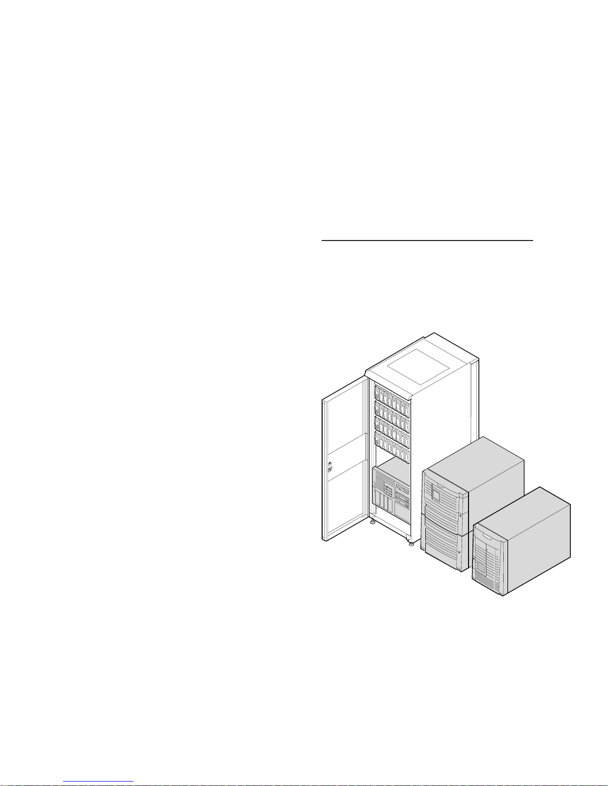
The system is available in three packages: a standalone tower, a
pedestal system with expanded storage capacity, and a rackmount system. Two models are available: an entry-level system
that supports 16 DIMMs (16 GB) and 6 PCI slots or a system
that supports 32 DIMMs (32 GB) and 10 PCI slots. Each system
variant is available with up to four processors.
Tru64 UNIX, OpenVMS, and Linux operating systems. The
AlphaServer ES40 system integrates into your current
operating environment and anticipates future needs with
upgrade capabilities.
For more information on Compaq AlphaServer ES40
systems, see:
http://www.compaq.com/alphaserver/servers.html
.
The chassis used in the tower is rotated 90 degrees and
installed in a pedestal enclosure or in a cabinet. Each chassis
provides space for up to twelve 1-inch Ultra3 disks. Up to
three BA36R StorageWorks shelves, or up to two Ultra3
Universal StorageWorks shelves can be installedin the
pedestal system; and up to six BA36R StorageWorks shelves,
or up to eight Ultra3 Universal StorageWorks shelves (singlebus or split-bus) can be installed in a cabinet.
Systems can be purchased with Tru64 UNIX or OpenVMS
operating systems installed. Or theycan bepurchased without
any operating system,allowing customers to install Linux.
Rackmount
Pedestal
Tower
PK0212
1
Page 4

Featuresand Benefits
• Leadership 64-Bit Architecture
The Alpha 64-bit architecture was introduced with the Alpha
21064 chip in 1992 and now the 21264, builds upon that
proven architecture.
• Performance
The Alpha 21264 chip, the world’s fastest microprocessor, is
offered with a switch-based interconnect that supports four
processors. This switch-based system provides a memory
bandwidth of up to 5.2 Gbytes/sec (peak) using two 256-bit
memory buses running at 83 MHz.
• Scalability
An entry-level system (Model 1) offers one processor, 512
MB memory, and 6 PCI slots. Model 2, can have 32 GB
memory, and 10 I/O slots. The pedestal system provides
space for another 21 disks using BA36R StorageWorks
shelves, or 28 disks using Universal StorageWorks shelves.
beyond the 12 in the chassis. The cabinet can house up to four
systems and/or additional disks. All variants support up to
four processors.
Internal to each chip is a 64-Kbyte instruction cache (I-cache)
and a 64-Kbyte data cache (D-cache).
• I-cache. 64 Kbytes, two-way set-associative, virtually
addressed cache with 64-byte blocks
• D-cache. 64 Kbytes, two-way set-associative, virtually
indexed, physically tagged, writeback cache with 64-byte
blocks
Chip Operation
Several key design choices were made in the chip architecture
to maximize performance: Four instructions are fetched each
cycle, and then how those instructions are handled boosts the
speed of execution. Register renaming assigns a unique
storagelocation with each write reference to a register,
avoiding register dependencies that can be a potential
bottleneck to processor performance.
Another design feature, out-of-order execution, permits
instructions to execute in an order different from the order that
the instructions are fetched. In effect, instructions execute as
quickly as possible. This allows for faster execution, since
critical path computations are started and completed as soon as
possible.
• Reliability and Availability
The AlphaServer ES40 uses the latest technologies to achieve
redundancy, error correction, and fault management. The
system has redundant fans and power supplies; fans, power
supplies, and disks can be hot plugged. The remote
management console (RMC) monitors, sends alerts, and
records possible error conditions. The RMC can be accessed
even if the system is completely down.
• ES40 Workstation
The system is also offered as a workstation and is calledthe
AlphaStation ES40.
Third-Generation Alpha Chip
The third generation of the Alpha microprocessor, the Alpha
21264, is a superscalar superpipelined implementation of the
Alpha architecture. The first offering of this chip was known
as EV6. These systems are offered with the EV67 chip (.28
micron) and the EV68 chip (.18 micron). Each chiphas over
15.2 million transistors. In our discussion here, the Alpha
21264 designation applies to all variants of the chip.
Designed for performance, the 21264 achieves this goal by
carefully studied and simulated architectural and circuit
analysis. The 21264 memory system also enables the high
performance levels. On-chip and off-chip caches provide for
very low latency data access, which allows for very high
bandwidthdataaccess. (InES40systemsthesizeoftheoffchip cache is 8 MB running at 222 MHz (dual data rate cache)
for EV67 and 8 MB running at 277 MHz DDR for EV68.)
In addition, the Alpha 21264 employs speculative execution to
maximize performance. It speculatively fetches and executes
instructions even though it may not know immediately
whether the instruction will be on thefinal execution path.
This is particularly useful, for instance, when the 21264
predicts branch directions and speculatively executes down the
predicted path. The sophisticated branch prediction in the
21264 coupled with the speculative and dynamic execution
extractsmaximum instruction parallelism from applications.
For more information about the chip, see:
http://www.compaq.com/alphaserver/download/ev6chip.pdf
Alpha 21264 Features
.
• Out-of-order instruction execution
• Large (64 Kbyte) on-chip data and instruction caches
• Improved branch prediction through intuitive execution
• Register renaming
• Increased bandwidth for high-speed access to second-
levelcacheandsystemmemory
• Motion video instructions
• Square root and divide instructions
• All instructions are 32 bits long and have a regular
instruction format
• Floating-point unit, supports DIGITAL and IEEE
floating-point datatypes
• 80 integerregisters, 64 bits wide
• 72 floating-point registers, 64 bits wide
2
Page 5
Model Variants
AlphaServer ES40 systems are offeredin twomodels. The
entry-level model provides connectors for four DIMMs on
each of the memory motherboards (MMBs) and connectors for
six PCI options on the PCI backplane.
Model 1 Model 2
1–4 CPUs 1–4 CPUs
Up to 16 GB memory Up to 32 GB memory
6PCIslots 10PCIslots
To upgrade from Model 1, you replace the PCI backplane and
the four memory motherboards. A Model 2 system has eight
DIMMs on each MMB (32 total) and 10 PCI slots.
CPU Upgrades
Upgrading from the 500 to 667 or 883 MHz processors
requires that the system board (54-25385-01) be a minimum
revision of E05.
SystemPackaging
Allsystemvariantsusethesamechassis,withspacefortwo
disk cages in the front. Each cage holds up to six 1-inch
Ultra3 SCSI disks.
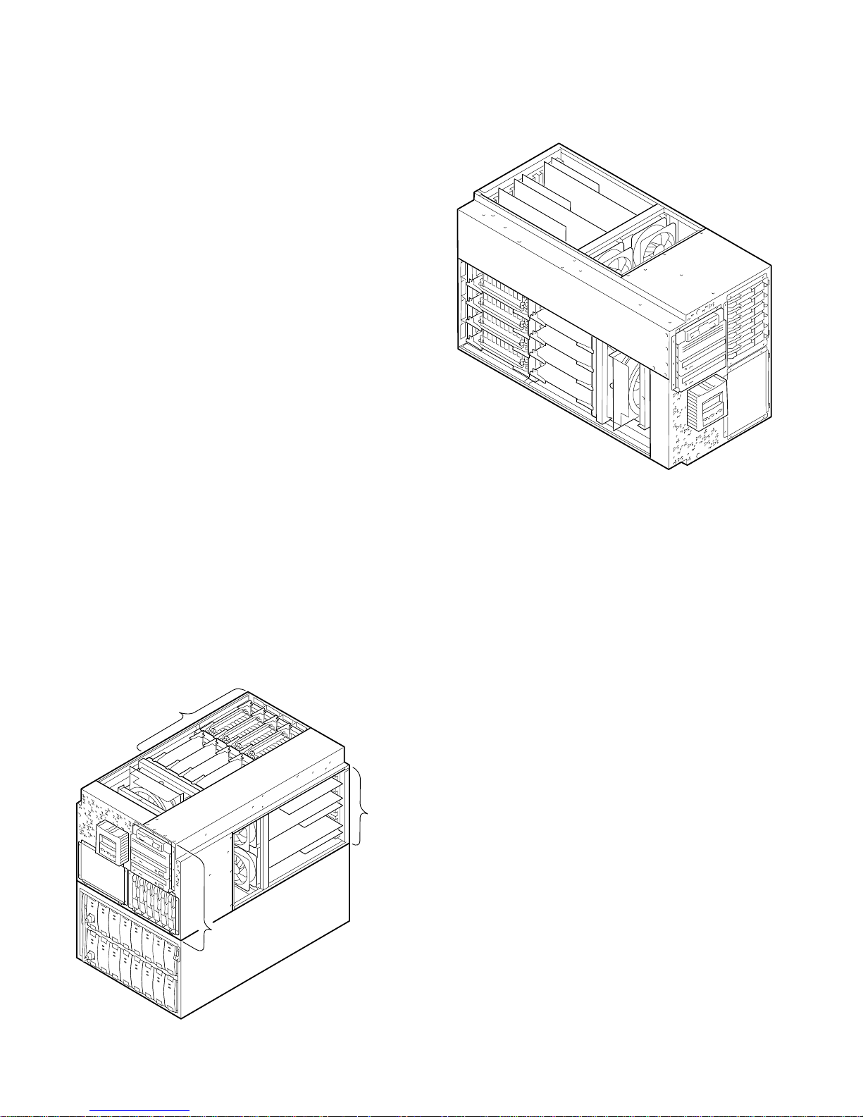
Chassis, Tower View
In the tower enclosure, the chassis is rotated 90 degrees, with
the control panel and removable media bays keeping their
same horizontal position as in the pedestal/rack system.
The chassis has a compartment for the CPUs and memory and
another one for the PCI I/O cards. The control panel, CD-ROM
and floppydrives, and two additional removable media bays are
in the front,along with space for up to two disk cages. The
power supplies are in the rear.
Chassis, Pedestal View
Additional storage is available in the pedestal enclosure. The
chassis is mounted over a box that can house up to three BA36R
StorageWorks shelves (two in the front and one in the rear), or
up to two Ultra3 Universal (single-bus or split-bus)
StorageWorks shelves.
CPUs and
Memory
Fans
IO
PK3245
Rackmount Chassis
When installed in a cabinet, the chassis has the same
orientation as that used in the pedestal. The chassis can be
mounted in the 67-inch or 79-inch M-series cabinet, which is a
19-inch wide RETMA cabinet. Each system requires 14
inches (8U) of vertical space. With the maximum number of
systems in a cabinet (four), there can be two StorageWorks
shelves. When the maximum number of disks is desired (six
shelves), there can be three systems. (These numbers are for
the H9A15 79-inch cabinet.)
Fans
Control Panel
and Drives
PK3243
3
Page 6
Architecture
This s ystem is designedto maximizethe potential of the
Alpha 21264 chip. The traditional bus interconnect has been
replaced by a switch-based interconnect system. With a bus
design, the processors, memory, and I/O modules share the
bus. As the number of bus users increases, the transactions
interfere with one another, increasing latency and decreasing
aggregate bandwidth. However, with a switch-based system
there is no degradation in performance as the number of
CPUs, memory, and I/O users increase. Although the users
increase, the speed is maintained.
With a switch-based, or point-to-point interconnect, the
performance remains constant, even though thenumber of
transactions multiplies. The switched system interconnect
uses a set of complex chips that route the traffic over multiple
paths. The chipset consists of one C-chip, two P-chips, and
eight D-chips.
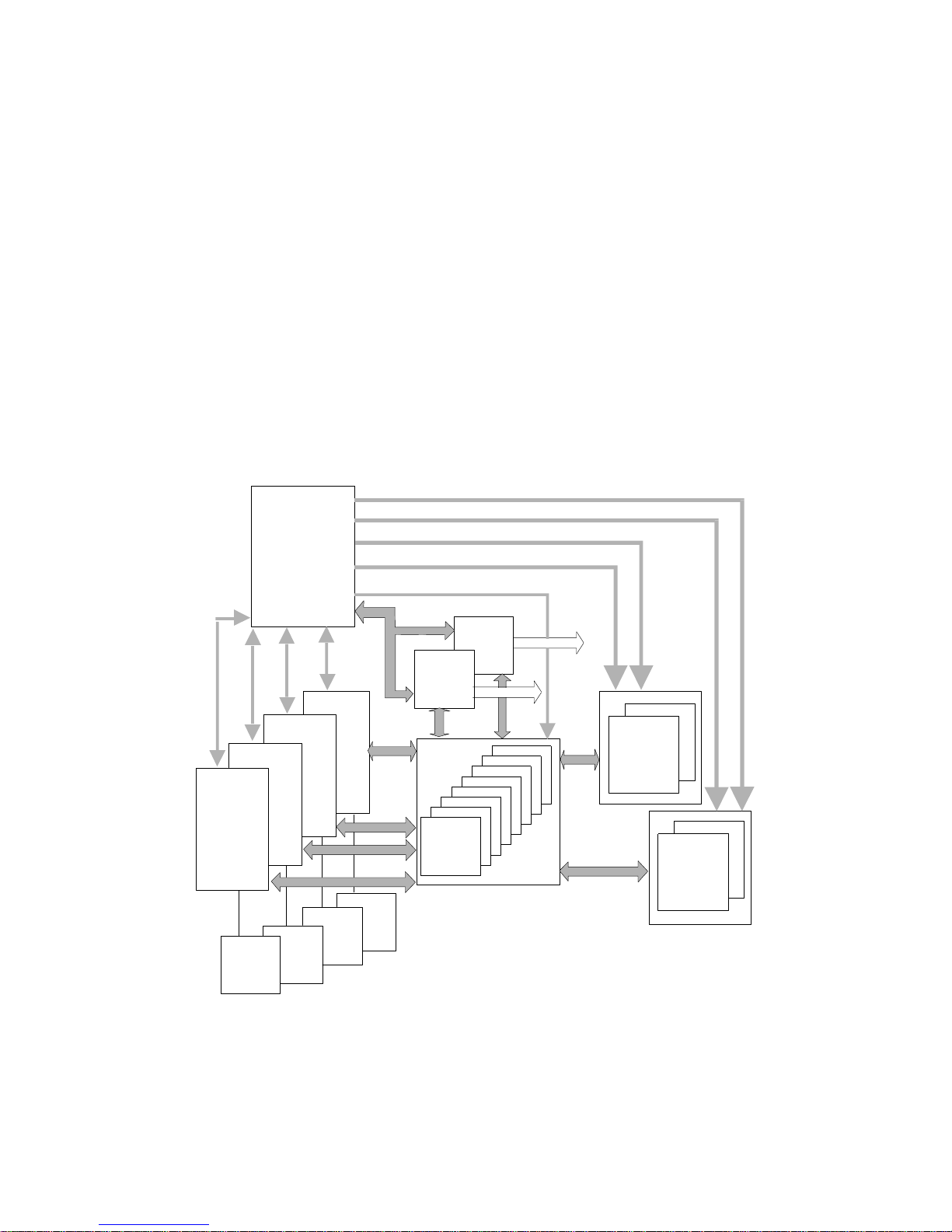
System Block Diagram
Command, Address, and Control lines for each Memory Array
• C-chip. Provides the commandinterface from the CPUs
and main memory. Although there is only one C-chip in
the system, it allows each CPU to do transactions
simultaneously.
• D-chips. Provide the data path for the CPUs, main
memory, and I/O.
• P-chips. Provide the interface to two independent 64-bit
33 MHz PCI buses.
This chipset is similar to that used in the AlphaServer DS20
system; however, this chipset supports up to four CPUs and up
to 32 Gbytes memory. Interleaving occurs when at least two
memoryarrays are used.
Two 256-bit memory buses support four memory arrays,
yielding a 5.2 Gbytes/sec system bandwidth. Transactions are
ECC protected. Upon the receipt of data, the receiver checks
for data integrity and corrects any errors.
First
CPU
CPUs
B-cache
C-chip
Control lines for D-chips
bus
AP
C
P-chip
P-chip
64 bit PC
PAD
Bus
CPU
Data
Bus
8 D-chips
64 bit PC
I
I
Memory
Data
Bus
1 or 2
Memory
Arrays
1 or 2
Memory
Arrays
1400A-99
KW
P
4
Page 7

SystemBoard
The interconnect switch is implemented on the system board
by the chipset consisting of one C-chip, two P-chips, and eight
D-chips. This complex chipset provides the data and address
path between the CPUs, memory, and the I/O subsystem.
A flash ROM holds the console code and the NVRAM data.
Connectors are provided for four CPU modules and four
memorymotherboards.
Component and Connector Locations
Connector to I/O
One corner of the board holds logic for the remote
management console (RMC).
On the back side of the module are connectors for the power
supplies. The I/O connector provides both signals and power
to the PCI backplane.
RMC Corner
J7
D-chip
J8
J5
D-chip
J6
P-chip
D-chip
D-chip
MMB1
MMB3
MMB0
MMB2
P-chip
D-chip
D-chip
D-chip
C-chip
D-chip
J17
J18
J34
J40
CPU3
CPU2
CPU1
CPU0
PK-0323-99
5
Page 8

Processor Module
An AlphaServer ES40 can have up to four CPU modules.
In addition to the Alpha chip, the CPU module has an 8-Mbyte
second-level cache and a DC-to-DC converter with heatsink
that provides the required voltage to the Alpha chip. Power-up
diagnostics are stored in a flash ROM on the module.
PK0271
Processor Configuration Rules
• The first CPU module is installed in CPU slot 0.
• Additional CPUs are installed in the next available slot.
• CPUs must be identical in speed and cache size.
Memory
Memory throughput in this system is maximized by the
following features:
• Two 256-bit wide memory data buses
• Very low memorylatency(120 ns) andhighbandwidth
with 12 ns clock
• ECC memory
The switch interconnect can move a large amount of data over
two independent memory data buses. Each data bus is 256
bits wide (32 bytes). The memory bus speed is 83 MHz. This
yields 2.67 GB/sec bandwidth per bus (32 x 83 MHz = 2.67
GB/sec). The maximum bandwidth is 5.2 GB/sec (2.67 x 2).
MMB2 MMB0 MMB3 MMB1
Address Arrays 0 & 1
Address Arrays 2 & 3
256 Data + 32 Check Bits
The design challenge was to maximize the capabilities of the
two wide data buses. Distributing the 256 data bits equally
over two memory motherboards (MMBs) was one solution:
simultaneously, in a r ead operation, 128 bits come from one
MMB and the other 128 bits come from another MMB, to
make one 256-bit read. Another 256-bit read operation can
occur at the same time on the other independent data bus.
In addition, two address buses per MMB (one for each array)
allow overlapping/pipelined accesses to maximize use of each
data bus. When all arrays are identical (same size and speed),
the memory is interleaved; that is, sequential blocks of memory are distributed across all four arrays.
6
Data
Bus 1
C-Chip
256 Data + 32 Check Bits
Data
Bus 0
To all eight D-ChipsTo all eight D-Chips
PK0272
Page 9
MemoryOptions
Each memory option consists of four 200-pin industrystandard DIMMs. The DIMMs are synchronous DRAMs.
The Model 1 system supports up to four memory options (16
DIMMs), and the Model 2 system supports up to eight options
(32 DIMMs). Memory options are available in the following
sizes:
• 512 Mbytes (128 MB DIMMs)
• 1 Gbyte (256 MB DIMMs)
• 2 Gbytes (512 MB DIMMs)
• 4Gbytes(1GBDIMMs)
With the 4 GB option, Model 1 supports 16 GB memory and
Model 2 supports 32 GB memory.
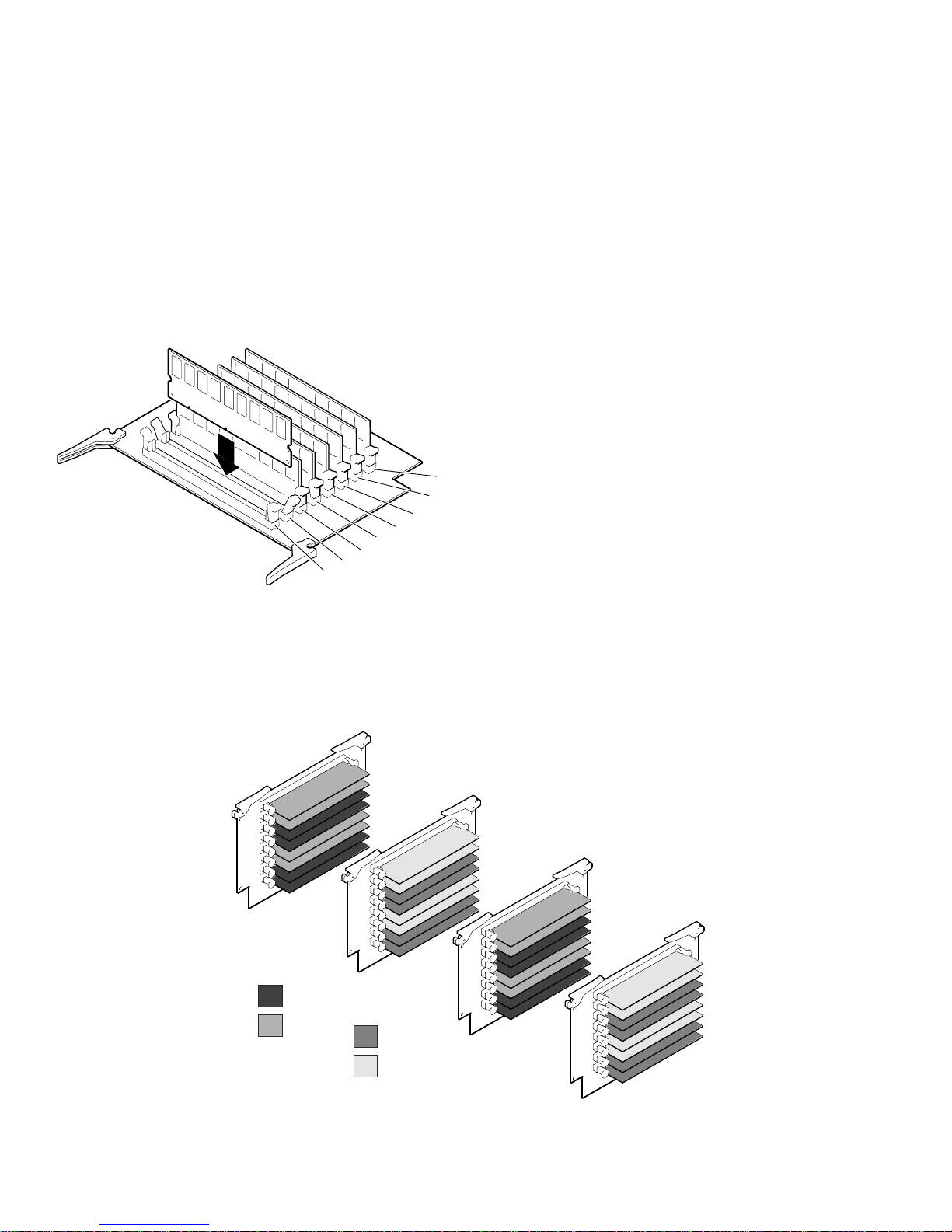
MemoryMotherboard
Memory Configuration
A memory option (or set) consists of four DIMMs, and all
fourDIMMsmustbethesamesize.
• Fill sets in numerical order. Populateall 4 slots in Set 0,
then populate Set 1, and so on.
• An array is one set for systems that support 16 DIMMs
and two sets for systems that support 32 DIMMs.
• DIMMsinanarraymustbethesamesizeandtype. For
example, suppose you have populated Sets 0, 1, 2, and 3.
When you populate Set 4, the DIMMs must be the same
size and type as those installed in Set 0. Similarly, Set 5
must be populated with the same size and type of DIMMs
as are in Set 1, and so on, as indicated in the following
table.
Array Model 1 System Model 2 System
0 Set 0 Set 0 and Set 4
1 Set 1 Set 1 and Set 5
2 Set 2 Set 2 and Set 6
3 Set 3 Set 3 and Set 7
• Systems that require full redundant power (three power
supplies) are restricted to a maximum of 24 Gbytes
memory.
MMB 2
1
2
3
4
5
6
7
8
PK-0324-99
Memory Performance Considerations
With one memory option (4 DIMMs) installed in either Model
1 or Model 2, memory operation interleaving will n ot occur.
With two memory options (8 DIMMs),memory read-write
operations are two-way interleaved. Interleaved operations
reduce the average latency and increase the memory throughput over noninterleaved operations. With four memory
options (16 DIMMs) installed, memory read-write operations
are four-way interleaved, maximizing memory throughput.
Memory Arrays and Sets on Memory Motherboards
Sets
7
7
5
5
3
Array 1
Sets 1 & 5
Array 3
Sets 3 & 7
3
1
1
MMB 0
Array 0
Sets 0 & 4
Array 2
Sets 2 & 6
Sets
6
6
4
4
2
2
0
0
MMB 3
Sets
7
7
5
5
3
3
1
1
Sets
6
6
4
4
2
2
0
0
MMB 1
PK0330-99
7
Page 10

System I/O
Two industry-standard PCI I/O buses allow you to use
inexpensive, widelyavailable I/O options. Both 32-bit and
64-bit PCI options can be used; 3.3V and 5V options are
supported.
The industry-standard PCI bus is the number one choice for
high-performanceI/O options, such as disk storageand h ighperformance videoapplications.
Block Diagram of I/O Control
The PCI bus implementation has the following characteristics:
• Fullycompliant with the PCI Version 2.1 Specification
• Operates at 33 MHz, delivering a peak bandwidth of 500
MB/sec; over 250 Mbytes/sec for each PCI bus
• 6 option slots (Model 1) or 10 option slots (Model 2)
• Supports three address spaces: PCI I/O, PCI memory, and
PCI configuration space
• Supports byte/word, tri-byte, and longword operations
• Exists in noncachedaddress space only
PCI 0
Flash ROM
(NVRAM functions)
Interrupts
Config
I/O Implementation
In a Model 2 system that has 10 I/O slots, PCI 0 has 4 slots,
and PCI 1 has 6 slots.In a Model 1 system with 6 slots, each
PCI h as 3 slots.
P-chip 0
C-chip
P-chip 1
PCI 1
Acer Labs
1543C Chip
COM1
COM2
Modem
Printer
Floppy
PCI Slot
PCI Slot
Keyboard
Mouse
CD-ROM
USB
PK-0319A-98
1 2 3 4 5 6 7
The Acer Labs 1543C chip provides the bridge from PCI 0 to
ISA. The C-chip controls accesses to memory on behalf of
both P-chips.
I/O Configuration Rules
A VGA controller, if present,must be in stalled in PCI 0.
I/O Ports
At the rear of the system are connectors offering access to two
serial communications ports, one modem port for the remote
management console, one parallel port, ports for the keyboard
and mouse, and two USB ports. TwoSCSI breakouts are also
on the back panel.
8
Pedestal/Rack
8
1. RMC modem port
2. COM2 serial port
3. Keyboard port
4. Mouse port
5. COM1 serial port
6. USB ports
7. Parallel port
8. SCSI breakouts
PK-0325-99
Page 11

System Control
Close monitoring and control of the system environment and
hardware is done by the remote management console (RMC).
This logic also allows the system operator to monitor the system from a remote location.The RMC logic is implemented
using a PIC17C44 microprocessor on the system board. The
RCM firmware code resides on the microprocessor and in
flashmemory. TheRMCispoweredbyanauxiliary5Vsupply, so even when the system is powered off at the control
panel the RMC can be accessed—so long as the system is
plugged in.
The RMC provides the following monitoring and control
functions:
• Monitors thermal sensors on the CPUs, the PCI
backplane, and the power supplies
• Monitors voltages, power supplies, and fans
• Handles hot swapping of power supplies and fans
• Controls the control panel displayand writes status
messages on the display
• Detects alert conditions such as excessive temperature,
fan failure, and power supply failure and sends an alert
• Shuts down the system if any fatal conditions exist
• Records error log information in nonvolatile RAM on
each failing device
Storage
Removable media in the chassis includes a CD-ROM drive,
floppy diskette drive, and two 5.25 inch half-height bays,
which can be combined for one 5.25 inch full-height bay.
AdiskcageinthefrontofthechassissupportsuptosixUltra3
SCSI Universal 1-inch disk drives (9.1, 18.2, or 36.4 GB).
The drives are available at 10,000 or 15,000 RPM. Another
disk cage can be added so that up to twelve disks can be
installed. Each cage requires its own SCSI adapter.
Storage shelves can be either BA36R StorageWorks shelves or
Ultra3 Universal StorageWorks shelves. The BA36R
StorageWorks shelf supports seven disks per shelf; the Ultra3
Universal StorageWorks shelf supports 7 disks (single-bus) or
14 disks (split-bus) per shelf.
The pedestal system can include:
• Up to three BA36R StorageWorks shelves
• Up to two Ultra3 Universal StorageWorks shelves
(single-bus or split-bus)
Fibre Channel
Available on these AlphaServer systems is the next storage
interface, Fibre Channel, which eliminates issues with today’s
SCSI interfaces such as distance, bandwidth, scalability, and
reliability. Fibre Channel (FC) is the answer to not only
server-to-storage connections but also to server-to-server
networking, because multiple protocols are supported. SCSI,
TCP/IP, video, or raw data can all take advantage of highperformance, reliable Fibre Channel technology.
With the KGPSA PCI Fibre Channel adapter, the ES40
systems provide a storage interconnect that is 2.5 times as fast
as UltraSCSI: 100 vs 40 Mbytes/sec data throughput. The
KGPSA adapter allows you to manage storage including the
HSG80 RAID controller in a switched FC topology.
RAID (Redundant Array of Independent Disks)
The system can be configured with optional PCI RAID
controllers to organizedisk data cost-effectively, improve
performance, and provide high levels of storage integrity.
Today, RAID is only availablewith StorageWorks shelves.
The optional RAID controllers have the following features:
• Support for hot-swap drives
• Automatic rebuild after h ot swap
• Console support for booting system from RAID
• RAID levels 0, 1, 0+1, 5
• Optionalwrite cache
• Optionalread cache
• Support for command queuing
Server Management
The AlphaServer products support important operational and
platform management requirements.
Operational Management
Server/Network Management. Compaq Insight Manager is
included with every system. This software tool allows you to
monitor and controlAlpha based servers. Insight Manager
consists oftwocomponents:a Windows-based console application and server- or client-based management data collection
agents. Management agents monitor over 1,000 management
parameters. Key subsystems are instrumented to make health,
configuration, and performance data available to the agent
software. The agents act upon that data, by initiating alarms in
the event of faults and by providing updated management information, such as network interface or storage subsystem performance statistics.
The rackmount cabinet can include:
• Up to six BA36R StorageWorks shelves
• Up to eight Ultra3 Universal StorageWorks shelves
Remote Server Management. The integrated remote management console (RMC) lets the operator perform several tasks
from a serial console: monitor the system power, temperature,
and fans, and reset, halt, and power the system on or off. The
monitoring can be done locallyor remotelythrough a modem.
9
Page 12

Platform Management
The AlphaServer ES40 systems support platform management
tasks such as manipulating and monitoring hardwareperformance, configuration, and errors. For example, the operating
systems provide a number of tools to characterize system performance and display errors logged in the system error log file.
In addition, system console firmware provides hardware configuration tools and diagnostics to facilitatequick hardware
installation and troubleshooting. The system operator can use
simple console commands to show the system configuration,
devices, boot and operational flags, and recorded errors. Also,
the console provides inventory support and configuration
management by giving access to serial numbers and revisions
of hardware and firmware.
Error Reporting
Compaq Analyze, a diagnostic service tool used to determine
the cause of hardware failures, is installed with the operating
systems. It provides automatic background analysis, as it
constantly views and reads the error log file. It analyzes both
single error/fault events and multiple events. When an error
condition is detected,it collects the error information and
sends it and an analysis to the user. The tool requires a
graphics monitor for its output display.
Memory Features
• The memory ECC scheme is designed to provide maxi-
mum protection for user data. The memoryscheme
corrects single-bit errors and detects double-bit errors and
total DRAM failure.
• Memory failover. The power-up diagnostics are designed
to provide the largest amount of usable memory, configuringarounderrors.
I/O Features
• ECC protection on the switch interconnect and parity
protectiononthePCIandSCSIbuses.
• Extensive error correction built into disk drives.
• Optionalinternal RAID improves reliabilityand data
security.
• Disk hot swap.
System Features
Auto reboot. On systems running Tru64 UNIX or OpenVMS,a
firmware environment variable lets you set the default action
the system takes on power-up, reset, or after an operating
system crash. For maximum system availability, the variable
can be set to causethe system to automaticallyreboot the
operating system after most system failures.
Security
• Front doors can be locked to prevent access to the disk
drives and the rest of the system.
• An interlock sensor switch shuts down power if the top
cover to the CPU/memoryarea is removed while power is
on.
• Password protection is offered by the SRM console and
RMC.
Reliability and Availability Features
The AlphaServer ES40 system achieves an unparalleled level
of reliability an d availabilitythrough the careful application of
technologies that balance redundancy, error correction, and
fault management. Reliabilityand availability features are
built into the CPU, memory, and I/O, and implemented at the
system level.
Processor Features
• CPU data cache provides error correction code (ECC)
protection.
• Parity protection on CPU cache tag store.
• Multi-tiered power-up diagnostics to verifythe
functionality of the hardware.
When you power up or reset the system, each CPU, in parallel,
runs a set of diagnostic tests. If any tests fail, the failing CPU
is configured out of the system. Responsibility for initializing
memoryand booting the console firmware is transferredto
another CPU, and the boot process continues. This feature
ensures that a system can still power up and boot the operating
system in case of a CPU failure. Messages on the operator
control panel power-up/diagnostic display indicate the test
status and component failure information.
Software installation. The operating systemsare factory
installed. Factory installed software (FIS) allows you to boot
and use your system in a shorter time than if you install the
software from a distribution kit.
Diagnostics. During the power-up process, diagnostics are
run to achieve several goals:
• Provide a robust hardware platform for the operating
system by ensuring that any faulty hardware does not
participate in the operating system session. This maximizes system uptime by reducing the risk of system
failure.
• Enable efficient, timely repair.
Audible beep codes report the status of diagnostic testing.
The system has a firmware update utility(LFU) that provides
update capability for console and PCI I/O adapter firmware.
A fail-safe loader provides a means of reloading the console in
the event ofcorrupted firmware.
Thermal management. The air temperatureand fan operation
are monitored to protect against overheating and possible
hardware destruction. Six fans provide front to back cooling,
and the power supplies, in the rear, have their own fans. If the
temperature rises, the system fans speed up; or if necessary to
prevent damage, the system shuts down. If the main fan, which
cools the system card cage, fails, a redundant fan takes over.
10
Page 13

Error handling. Parity and other error conditions are detected
on the PCI buses. The memory checking scheme corrects
single-bit errors and detects double-bit errors. Multiple ECC
corrections to single-bit errors detected by the operating
systems help in determining where in the system the error
originated. Errors are logged for analysis.
Disk hot swap. The hardware is designed to enable hot swap
of disks. Hot swap is the removal of a disk while the rest of
the system remains powered on and continues to operate. This
feature contributes significantly to system availability. Since
many disk problems can be fixed without shutting down the
entire system, userslose access only to the disksthat are
removed.
N+1 power redundancy. A second or third power supply can
be added to provide redundant power to the chassis. A second
power supply is needed for more than two CPUs or if a second
disk cage is installed. In this case the third supply provides
redundancy. The third power supply provides full N+1 redundancyforconfigurationsusingupto24Gbytesmemory.
Power supplies are 720 watts (DC). Eachhas two LEDs to
indicate the state of power to the system.
An external UPS can be purchased to support critical customer
configurations. Because power is maintained for the entire
system (CPU, memory, and I/O), power interruptions are
completely transparent to users.
Installation and Maintenance
The systems are designed for easy hardware, software, and
option installation. Options orderedwith a system are preinstalled and tested at the factory. The operating systems are
also installed at the factory.
Additional CPUs, memory, power supplies, and disks can be
added to the tower and pedestal systems by anyone with
appropriate technical training and experience. Installation of
components in a rackmount system is reserved for service
providers and self-maintenance customers.
PCI to Memory Channel Interconnect
Under Tru64 UNIX and OpenVMS, you can build high-availabilityclusters using the PCI to Memory Channel interconnect. The Memory Channel interconnect is a high-bandwidth,
low-latency PCI-based communications interconnect for up to
eight AlphaServer systems. Data written to one computer's
memoryis shared by other computers on the Memory Channel
bus.
The PCI adapter is the interface between a PCI and a Memory
Channel bus. This bus is a memory-to-memory computer
system interconnect that permits I/O space writes in one
computing node to be replicated into the memories of all other
nodes on the Memory Channel bus. A writeperformed by any
CPU to its r eflected address region results in automatic
hardware updates to memory regions in other nodes. One
node’s write is “reflected” to other nodes as a direct side effect
of the local write. This provides a memory region with
properties similar to a high-performance shared memory
across a group ofnodes.
Operating System Support
For clustered Tru64 UNIX systems, TruCluster Software
solutions allow users access to network services and provide
further failover recovery from server,network, or I/O failures.
Tru64 UNIX cluster systems use the SCSI bus and/or PCI to
Memory Channel interconnect bus between disks and systems.
OpenVMS cluster systems use the CI, SCSI, Ethernet, FDDI,
and Memory Channel as the interconnect between disks and
systems.
The primary means of clustering AlphaServer ES40 systems
depends on the operating system.
• CI clusters, OpenVMS only
• Memory Channel, Tru64 UNIX and OpenVMS
• SCSI clusters, Tru64 UNIX and OpenVMS
Clustering
A cluster is a loosely coupled set of systems that behaves (is
addressed and managed) like a single system, but provides
high levels of availability through redundant CPUs, storage,
and data paths. Clusters are also highly scalable; that is, CPU,
I/O, storage, and application resources can be added incrementallyto efficiently in crease capacity. For customers, this
translates to reliable access to system resources and data, and
investment protection of both hardware and software.
Clustering allows multiple computer systems to communicate
over a common interface, share disks, and spread the computing load across multipleCPUs. Clustering is implemented
using our traditional interconnects and using the newest technology.
11
Page 14

Performance and Benchmarking
Compaq has an ongoing program of performance engineering,
using industry-standard benchmarks that allow comparisons
across major vendors’ systems. These benchmarks against
competitive systems are based on comparable CPU performance, coupled with comparable memory and disk expandability.
See Table 1 for the record-breakingperformance numbers of
the AlphaServer ES40 systems
System performance, however, is highly dependent upon
application characteristics. Thus, benchmark information is
one helpful “data point” to be used in conjunction with other
purchase criteria such as features, service, and price.
Sources of Performance Information
Performance information is available on the Internet.
http://www.compaq.com/alphaserver/performance/index.html
http://www.ideasinternational.com/benchmark/spec/specfp_s2000.html
Service and Support
Compaq provides a comprehensive set of services that
range from migration, consulting, and training, to direct
support of Alpha systems, software, and applications. For
information on Compaq Services, point your Web browser to
http://www.compaq.com/services
HardwareWarranty
The AlphaServer ES40 system and components, including
CPU, memory, PCI controllers, and power supplies, have a
3-year on-site, 5-day per week, 9-hour per day hardware
warrantywith n ext-day response time.
StorageWorks components contained in the pedestal or cabinet
systems are supported by the comprehensive StorageWorks
warranty: five years for disks, three years for controllers, two
years for tape devices, and one year for other components. The
first year includes on-sitenext-dayresponsetime. Network
products in the pedestal or cabinet systems carry the network
products warranty.
.
Informationfor Compaq Partners
If you are a Channel or Reseller Partner, you can find the tools,
resources, and information you need to conduct Compaq business online on the secure Compaq Partner Network extranet site:
http://CPN.compaq.com
Also see the Compaq Solutions Alliancesite at
http://csa.compaq.com
Users can upgrade to higher levels of service through a variety
of hardware supplemental services.
Software Warranty
The warranty for Tru64 UNIX and OpenVMS is conformance
to SPD with advisory telephone support for a period of 90
days. Users can upgrade to higher levels of service through a
variety of software supplemental services.
12
Page 15

Compaq AlphaServer ES40 SystemDiagrams
8
7
6
4
1
1. Control panel
2. CD-ROM drive
3
6
2
5
9
PK3244
3. Removable media bays
4. Floppy diskette drive
5. Storage drive bays
6. Fans
7. CPUs
8. Memory
9. PCI slots
Pedestal/Rack
9
1 2 3 4 5 6 7
1. RMC modem port
2. COM2 serial port
3. Keyboard port
10
4. Mouse port
5. COM1 serial port
6. USB ports
7. Parallel port
8. SCSI breakouts
PK-0327-99
9. PCI slots
10. Power supplies
8
13
Page 16

SystemFeatures at a Glance
Table 1 provides a quick reference to features of the Compaq AlphaServer ES40 systems.
Table 1 AlphaServer ES40 Features
System Features
CPU features 6/667 6/833
Symmetric multiprocessing 1–4 processors 1–4 processors
CPU clock speed Alpha 21264A / 667 MHz Alpha 21264A / 833 MHz
Cache size (on chip/on board) 64 KB I, 64 KB D / 8 MB ECC DDR 64 KB I, 64 KB D / 8 MB ECC DDR
Memory (maximum)
Performance 1 CPU 2 CPUs 4 CPUs 1 CPU 2 CPUs 4 CPUs
SPECint2000 433 544
SPECfp2000 562 658
SPECint_rate2000 5.05 10.3 19.8 6.31 12.5 24.7
SPECfp_rate2000 6.50 12.2 21.9 7.63 14.0 25.5
SPECweb99 2,304
SPECjvm98 71.9 83.5 100 104
SPECjbb2000 23,787 15,152 28,032
SPECsfs97 .v3 14,157
TPC-C 30,738 tpmC @ $29
Standard Features
Storage
Removable media CD-ROM, floppy diskette, two HH 5.25” removable media bay
System chassis storage 12 disks (437 GB with 36.4 GB disks) Ultra3 SCSI
Pedestal
Disk Drive Cages PLUS BA36R StorageWorks Shelves OR Universal StorageWorks Split-Bus Shelves
12 disks (437 GB @ 36.4 GB) 21 disks (764 GB @ 36.4 GB) 28 disks (1 TB @ 36.4 GB)
H9A10 cabinet
Disk Drive Cages BA36R StorageWorks Shelves Universal StorageWorks Split-Bus Shelves
24 disks (874 GB @ 36.4 GB) 42 disks (1.5 TB @ 36.4 GB) 112 disks (4 TB @ 36.4 GB)
H9A15 cabinet
Disk Drive Cages BA36R StorageWorks Shelves Universal StorageWorks Split-Bus Shelves
36 disks (1.3 TB @ 36.4 GB) 42 disks (1.5 TB @36.4 GB) 112disks (4 TB @ 36.4 GB)
I/O System
I/Oslots 6PCIslotsinModel1or10PCIslotsinModel2
Maximum PCI throughput Over 500 MB/sec with two 256 MB/sec buses
High Availability Features
System System auto reboot, thermal management, remote system management, RAID0, 1, 0+1, 5, hot swap of
OpenVMS clusters CI, Ethernet, SCSI, FDDI, PCI to Memory Channel Interconnect
Tru64 UNIX TruClusters Solutions SCSI, PCI to Memory Channel Interconnect
Operating Systems
Warranty
Hardware 3-year, on-site, 5 day x 9 hour warrantywith 24-hour response
Software 90-day telephone advisory support for OpenVMS and Tru64 UNIX
16 GB in Model 1 and 32 GB in Model 2 *
67/667 68/833
1.44 MB diskette drive, CD-ROM drive, 1 RMC dedicated serial port, 2 serial ports, 1 parallel port,
keyboard and mouse, i ntegrated remotesystem management console, operating system license and
customer documentation,Internet software
Total capacity:1.2TB Total capacity:1.5TB
Total capacity: 2.4 TB Total capacity: 4.9 TB
Total capacity: 2.8 TB Total capacity:5.4TB
disks, power supplies, and fans, memory failover, ECC memory, ECC cache, N+1 power supply,*
SMP CPU failover, error logging, optional uninterruptible power supply
Tru64 UNIX, OpenVMS, Linux
* Configurations requiring N+1 r edundant power are restricted to a maximum of 24 Gbytes memory; if full redundancyis not required,
32 Gbytes memory is supported.
14
Page 17

Physical Characteristics
Table 2 details basic physical characteristics of the system,
and Table 3 gives the electrical characteristics.
Table 2 AlphaServer ES40 Physical Characteristics
Dimensions Tower Pedestal Rackmount
Height 50.8 cm (20.0 in.) 78.2 cm (30.8 in.) 35.2 cm (13.87 in.)
Width 38.7 cm (15.25 in.) 50.8 cm (20.0 in.) 44.7 cm (17.6 in.)
Depth 78.7 cm (31.0 in.) 80.6 cm (31.75 in.) 76.5 cm (30.1 in.)
Weight 65 kg (143 lb) typical;
96 kg (211 lb) maximum
Environmental
Temperature Operating
Relative humidity
Maximum wet bulb temperature
Minimum dew point temperature Operating 2° C (36° F)
Heat dissipation
Tower and Rack
Pedestal
H9A10/H9A15
Airflow and quality
Altitude
Vibration Operating 10–500 Hz .1 G peak
Mechanical shock
Acoustics—Declared values per ISO 9296 and ISO 7779
Current values for specific configurations are available from Compaq. 1 B = 10 dBA
Acoustics
Idle
Operating
127 kg (280 lb) typical;
159 kg (350 lb) maximum
Storage (60 days)
Rate of change
Operating
Nonoperating
Storage (60 days)
Rate of change
Operating
Storage (60 days)
Nominal
900 w, 3074 BTU/hr
1480 w, 5054 BTU/hr
Configuration dependent
Intake location
Exhaust location
Operating
Nonoperating
Operating
Tower/Pedestal
M-Series Cabinet
L
,B
Wad
6.6
6.6
With brackets, slides, & cables
Nominal59kg(130lb)
Maximum92kg(202lb)
10–35° C (50–95° F)
–40 to 66° C (–40 to 151° F)
11° C/hr (20° F/hr)
20–80%
20–80%
10–95%
20%/hr.
28° C (82° F)
46° C (115° F)
Maximum
1300 w, 4440 BTU/hr
2400 w, 8196 BTU/hr
4800 w, 16392 BTU/hr
Front
Rear–Tower, Pedestal, Rack
Rear/Top–H9A10/H9A15
3037 m (10,000 ft)
12,190 m (40,000 ft)
7.5 G, 10 +/– 3ms
5.0 G, 10 +/– 3ms
L
, dBA (bystander position)
pAm
48
48
Table 3 AlphaServer ES40 Electrical Characteristics
Nominal voltage (Vac)
Voltage range (Vac)
100 120 200–240
90–110 110–128 180–250
temporary condition)
Power source phase
Nominal frequency(Hz)
Frequencyrange (Hz)
Single Single Single
50/60 50/60 50/60
49–51/59–61 49–51/59–61 49–51/59–61
RMS current(max.steadystate)
Tower and Rackmount
Single power cord
Multiple power cords
11.0 A 8.5 A 5.0 A
6.5 A 5.3 A 3.0 A
Pedestal
Each power cord
12.0 A 10.5 A 7.0 A
M-Series cab config.-dependent
Nominal voltage (Vac)
Each power cord
NOTE: Power supplies are universal,PFC, auto ranging,100 / 120 / 200–240 Vac.
100 120 220–240
24 A 24 A 16 A
15
Page 18

© 2001 Compaq Computer Corporation
Compaq, the Compaq logo, Compaq Insight Manager, AlphaServer,
StorageWorks, and TruCluster Registered in U.S. Patent and T rademark
Office. OpenVMS and Tru64 are trademarks of Compaq Informatio n
Technologies Group, L.P. in the United States and other countries.
Linux is a registered trademarko f Linus Torvalds in several countries.
UNIX is a trademark of The Open Group in the United States and other
countries. All other product names mentioned herein may be trademarks of
their respective companies.
Compaq shall not be liable for technical or editorial errors or omissions
containedherein. The informationin this document is provided “as is”
without warranty of any kind and is subject to change without notice. The
warranties for Compaq products are set forth in the express limited warranty
statements accompanying such products. Nothing herein should be construed
as constitutingan additional warranty.
 Loading...