

Page 1

Hardware Reference Guide
Compaq Deskpro EN Series of Personal Computers
Slim Desktop Models
Page 2

Hardware Reference Guide
Compaq Deskpro EN Series
of Personal Computers
Slim Desktop Models
Page 3

Notice
Compaq Computer Corporation shall not be liable for technical or editorial
errors or omissions contained herein. The information in this guide is subject
to change without notice.
© 2000 Compaq Computer Corporation. Except for use in connection with the accompanying
Compaq product, no part of this guide may be photocopied or reproduced in any form without
prior written consent from Compaq Computer Corporation.
COMPAQ, the Compaq logo, and Deskpro Registered in U.S. Patent and Trademark Office.
Microsoft, Windows, Windows NT, and other names of Microsoft products referenced herein
are trademarks or registered trademarks of Microsoft Corporation.
Intel and Pentium are registered trademarks of Intel Corporation. Celeron and MMX are
trademarks of Intel Corporation.
All other product names mentioned herein may be trademarks or registered trademarks of their
respective companies. Printed in U.S.A.
The following words and symbols mark special messages throughout this guide:
WARNING: Text set off in this manner indicates that failure
to follow directions could result in bodily harm or loss of life.
CAUTION: Text set off in this manner indicates that failure
to follow directions could result in damage to equipment or
loss of information.
Hardware Reference Guide
Compaq Deskpro EN Series of Personal Computers
Slim Desktop Models
First Edition (October 2000)
Part Number 178171-002
Compaq Computer Corporation
Page 4

chapter 1
Installation Guidelines
Installation Sequence ............................................................................................................... 1-1
When to Reconfigure the Computer......................................................................................... 1-3
chapter 2
Hardware Upgrades
Serviceability Features............................................................................................................. 2-1
Removing the Access Panel ............................................................................................... 2-1
Rotating the Drive Cage..................................................................................................... 2-3
Internal Components (Intel 815e Chipset) ............................................................................... 2-4
Installing Additional Memory.................................................................................................. 2-5
DIMMs............................................................................................................................... 2-5
Memory Module Installation.............................................................................................. 2-5
Installing an Expansion Card ................................................................................................... 2-7
Removing an Expansion Slot Cover................................................................................... 2-7
Removing or Installing a PCI Card .................................................................................... 2-8
Installing Additional Drives................................................................................................... 2-10
Removing a Blank Drive Bezel........................................................................................ 2-10
Installing a Diskette, CD-ROM, DVD-ROM, or Tape Drive........................................... 2-11
Installing a Hard Drive..................................................................................................... 2-13
Removing a CD-ROM Drive from the Drive Cage ............................................................... 2-16
Removing a Diskette Drive from the Drive Cage .................................................................. 2-17
Removing a Hard Drive from the Drive Cage ....................................................................... 2-18
Smart Cover Lock.................................................................................................................. 2-20
Using the Smart Cover FailSafe Key ............................................................................... 2-20
CONTENTS
Hardware Reference Guide iii
Page 5

appendix a
Specifications
.................................................................................................................................... A-1
appendix b
Hard Drive Installation Guidelines
Using the Cable-Select Feature with Ultra ATA Devices........................................................B-1
Installing SCSI Devices ...........................................................................................................B-2
Guidelines for Installing Optional SCSI Devices...............................................................B-2
Cabling for Optional SCSI Devices ...................................................................................B-4
Using SCSISelect with SCSI Devices ................................................................................B-5
appendix c
Battery Replacement
..........................................................................................................................C-1
appendix d
Security Lock Provisions
Installing a Cable Lock ........................................................................................................... D-1
appendix e
Electrostatic Discharge
Preventing Electrostatic Damage .............................................................................................E-1
Grounding Methods .................................................................................................................E-2
appendix f
Routine Computer Care and Shipping Preparation
Routine Computer Care ...........................................................................................................F-1
CD-ROM Drive Precautions....................................................................................................F-2
Operation............................................................................................................................F-2
Cleaning ............................................................................................................................. F-2
Safety ................................................................................................................................. F-2
Shipping Preparation................................................................................................................ F-3
iv Contents
Index .....................................................................................................................................................I-1
Page 6

Installation Sequence
chapter
1
INSTALLATION GUIDELINES
This guide explains how to remove the computer cover or access panel
and install the following optional equipment upgrades:
Additional system memory
Expansion card
Optional drive
Security lock
Replacement battery
This chapter includes information about the general installation
sequence for Deskpro personal computers, and about when to
reconfigure the computer to ensure that it recognizes the newly installed
equipment.
It is very important that you follow this sequence of steps to ensure the
proper installation of any optional equipment.
1. If your computer includes the Smart Cover Lock feature and you
have set the lock, use Computer Setup to unlock the lock and
disable the Smart Cover Sensor.
For more information about Computer Setup, refer to the Computer
Setup guide.
Hardware Reference Guide 1-1
Page 7
2. If the computer is already on, turn it off and disconnect the power
cord from the wall outlet.
WARNING: To reduce the risk of personal injury from electrical
!
shock and/or hot surfaces, be sure to disconnect the power cord from
the wall outlet, and allow the internal system components to cool
before touching.
WARNING: To reduce the risk of electrical shock, fire, or damage to
!
the equipment, do not plug telecommunications/telephone connectors
into the network interface controller (NIC) receptacles.
CAUTION: Static electricity can damage the electronic components
of the computer or optional equipment. Before beginning these
procedures, ensure that you are discharged of static electricity by
briefly touching a grounded metal object. Refer to Appendix E,
“Electrostatic Discharge,” for more information.
3. Open the computer by removing its outside cover. Refer to the
procedures for removing the computer cover or access panel.
4. Install any optional equipment. Refer to the applicable sections of
this guide or to the documentation provided with the optional
equipment for instructions.
5. Replace the computer cover.
6. Turn on the monitor, computer, and any devices you want to test.
1-2 Installation Guidelines
7. Reconfigure the computer, if necessary. Refer to the Computer
Setup guide for instructions about using Computer Setup.
If you normally lock the Smart Cover Lock, use Computer Setup to
relock the lock and enable the cover removal sensor.
Page 8

When to Reconfigure the Computer
System configuration is the process of specifying the devices and
programs that make up a computer system. When you add or remove
optional equipment, the computer must be reconfigured to recognize
these changes.
Windows 95 and later operating systems automatically recognize all
Plug and Play devices installed. However, if the device is not a Plug and
Play device or is not automatically detected after installation, follow
these instructions:
In Windows 95 and later operating systems, select the Add New
Hardware icon in the Control Panel and follow the instructions on
the screen.
To reconfigure the computer in Windows NT version 4.0, use the
software utility provided with the newly installed hardware.
Hardware Reference Guide 1-3
Page 9
Serviceability Features
Removing the Access Panel
chapter
2
HARDWARE UPGRADES
Your computer includes features that make it easier to upgrade and
service.
The quick release cover latches, located near the rear on each side of
the unit, allow easy removal of the access panel without the use of tools
or thumbscrews.
WARNING: Before removing the computer cover, ensure that the
!
computer is turned off and that the power cord is disconnected from
the electrical outlet.
1. If you have locked the Smart Cover Lock, use Computer Setup to
2. Shut down the operating system properly, then turn off the
If you have not already done so, you will need to loosen the
silver shipping thumbscrew from the center of the rear panel
before removing the cover.
unlock the lock and disable the Smart Cover Sensor.
computer and any external devices.
Hardware Reference Guide 2-1
Page 10
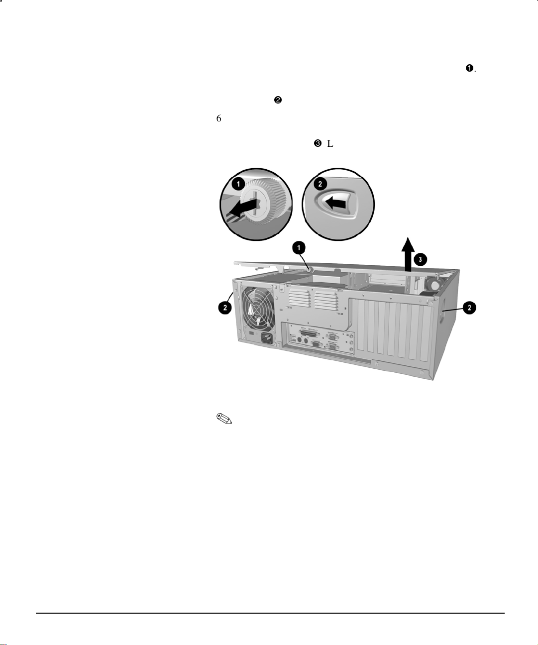
3. Disconnect the power cord from the power outlet.
4. Loosen the retaining screw located on the back of the unit
5. Slide the cover latches on the sides near the back of the
computer
6. Lift up the back of the access panel and pull it toward the back of
the unit about 1 inch (2.5 cm) so the tabs on the front of the access
panel clear the case
.
. Lift the access panel up and off the unit.
.
2-2 Hardware Upgrades
Removing the Access Panel
The configuration label located inside the computer cover
provides additional information.
Another label located inside the computer chassis provides
information about diagnosing computer conditions using the
power and hard drive LEDs.
Page 11
Rotating the Drive Cage
The rotating drive cage allows access to all drive bays for easy
installation of additional drives, requiring no drive rails or brackets.
With the drive cage rotated out from the chassis, you can easily connect
the drive power and signal cables.
1. If you have locked the Smart Cover Lock, use Computer Setup to
2. Shut down the operating system properly, then turn off the
3. Disconnect the power cord from the power outlet.
4. Remove the access panel.
5. Grasp the back of the drive cage and rotate it to its upright
When installing optional drives, you must install guide screws
to ensure the drive will line up correctly in the drive cage.
Compaq has provided extra guide screws, installed in the
bottom of the computer chassis, next to the power supply.
WARNING: Before removing the access panel, ensure that the
!
computer is turned off and that the power cord is disconnected from
the electrical outlet.
unlock the lock and disable the Smart Cover Sensor.
computer and any external devices.
position
. The cage remains connected to the chassis.
Rotating the Drive Cage to an Upright Position
Hardware Reference Guide 2-3
Page 12
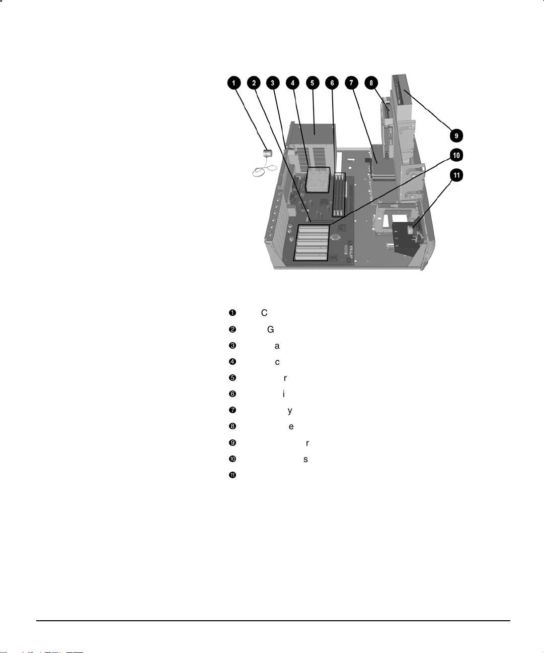
Internal Components (Intel 815e Chipset)
Internal Components in Intel 815e–Based Desktop Models
Cable lock (optional)
AGP graphics slot
Smart Cover Lock
Processor
Power supply
Dual-inline memory module (DIMM) sockets
Primary hard drive
Diskette drive
CD-ROM drive
PCI expansion slots
Speaker
2-4 Hardware Upgrades
Page 13
Installing Additional Memory
The computer comes with synchronous dynamic random access
memory (SDRAM) dual inline memory modules (DIMMs).
DIMMs
The memory sockets on the Intel 815e chipset–based system board can
be populated with industry-standard DIMMs. These memory module
slots are populated with at least one preinstalled memory module. To
achieve the maximum memory support, you may be required to replace
the preinstalled DIMM with a higher capacity DIMM.
For proper system operation, the DIMMs must be industry-standard
168-pin, unbuffered PC100– or PC133– compliant SDRAM DIMMs,
depending on the model. The SDRAM DIMMs must support CAS
Latency 2 or 3 (CL = 2 or CL = 3). They must also contain the
mandatory Joint Electronic Device Engineering Council (JEDEC)
Serial Presence Detect (SPD) information. DIMMs constructed with x4
SDRAM are not supported; the system will not start using unsupported
DIMMs.
The Intel 815e chipset supports both PC100 and PC133 SDRAM
DIMMs. PC133 DIMMs should be used for optimal performance. If
both PC100 and PC133 SDRAM DIMMs are installed in a computer,
the system memory will run at the lower 100Mhz speed. Some
configurations of PC133 SDRAMs may run at 100Mhz, instead of
133Mhz.
Memory Module Installation
CAUTION: Your memory module sockets have gold metal contacts.
When upgrading your memory, it is important to use memory
modules with gold metal contacts to prevent corrosion and/or
oxidation resulting from having incompatible metals in contact with
each other.
CAUTION: Static electricity can damage the electronic components
of the computer or optional cards. Before beginning these
procedures, ensure that you are discharged of static electricity by
briefly touching a grounded metal object. Refer to Appendix E,
“Electrostatic Discharge,” for more information.
CAUTION: When handling a memory module, be careful not to touch
any of the contacts. Doing so may damage the module.
Hardware Reference Guide 2-5
Page 14
1. If you have locked the Smart Cover Lock, use Computer Setup to
unlock the lock and disable the Smart Cover Sensor.
2. Shut down the operating system properly, then turn off the
computer and any external devices, then disconnect the power cord
from the power outlet.
3. Remove the access panel and locate the memory module sockets.
WARNING: To reduce risk of personal injury from hot surfaces,
!
allow the internal system components to cool before touching.
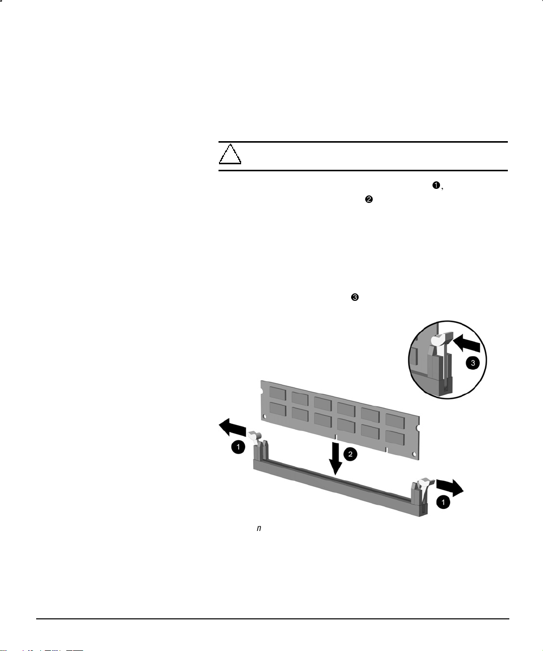
4. Open both latches of the memory module socket , and insert the
memory module into the socket
Begin by installing a module into the socket nearest the preinstalled
module, and install the modules following the numerical order of
the sockets.
A memory module can be installed in only one way. Match the
notch on the module with the tab on the memory socket. Push the
module down into the socket, ensuring that the module is fully
inserted and properly seated
.
.
2-6 Hardware Upgrades
Installing a DIMM
Page 15
Installing an Expansion Card
Your computer contains expansion slots, as shown in the “Internal
Components” section of this chapter. Each slot can accommodate an
expansion card up to 6.88 inches (17.48 cm) in length.
Removing an Expansion Slot Cover
1. If you have locked the Smart Cover Lock, use Computer Setup to
unlock the lock and disable the Smart Cover Sensor.
2. Shut down the operating system properly, turn off the computer
and any external devices, then disconnect the power cord from the
power outlet.
3. Remove the access panel.
4. Locate the correct vacant expansion card slot on the back of the
computer.
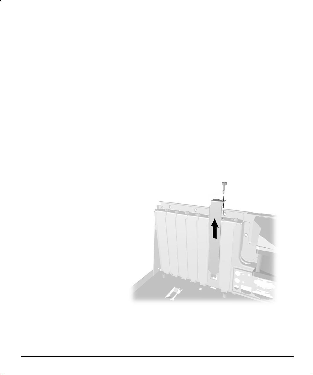
5. Remove the screw at the top of the expansion slot cover, then
remove the expansion slot cover from the slot as illustrated.
Removing a Screw and Expansion Slot Cover
Hardware Reference Guide 2-7
Page 16

Removing or Installing a PCI Card
1. If you have locked the Smart Cover Lock, use Computer Setup to
unlock the lock and disable the Smart Cover Sensor.
2. Shut down the operating system properly, turn off the computer
and any external devices, then disconnect the power cord from the
power outlet.
3. Remove the access panel.
If installing an expansion card, skip to step 9.
4. To remove an expansion card, disconnect any cables attached to the
expansion card.
5. Remove the screw at the top of the expansion slot.
6. Hold the card at each end and carefully rock it back and forth until
the connectors pull free from the slot. Be sure not to scrape the card
against other components.
7. Store the card in anti-static packaging.
8. Install an expansion slot cover or new expansion card to close the
open slot.
If not installing a new expansion card, skip to step 13.
9. To install a new expansion card in an open slot, remove the
expansion slot cover.
2-8 Hardware Upgrades
Page 17

10. Slide the expansion card into the expansion slot and press it firmly
into place.
Removing or Installing an Expansion Card
11. Replace the screw at the top of the expansion slot.
12. Replace the access panel.
13. Connect external cables to the installed card, if needed.
14. Reconfigure the computer, if necessary. Refer to the Computer
If you normally lock the Smart Cover Lock, use Computer Setup to
When you install an expansion card, make sure you press
firmly on the card so that the whole connector seats properly in
the expansion card slot.
Setup Guide for instructions about using Computer Setup.
relock the lock and enable the Smart Cover Sensor.
Hardware Reference Guide 2-9
Page 18

Installing Additional Drives
When installing additional drives, follow these guidelines:
Use the green pull tabs to disconnect the diskette and hard drive
cables from the drives.
For optimal performance, connect hard drives to the primary IDE
controller. Connect expansion devices, such as IDE CD-ROM,
tape, and diskette drives to the secondary controller.
You must install guide screws to ensure the drive will line up
correctly in the drive cage. Compaq has provided extra guide
screws, installed in the bottom of the computer chassis, next to the
power supply. Some options use M3 metric thread hardware. The
Compaq-supplied metric screws are black.
Removing a Blank Drive Bezel
1. If you have locked the Smart Cover Lock, use Computer Setup to
unlock the lock and disable the Smart Cover Sensor.
2. Shut down the operating system properly, turn off the computer
and any external devices, then disconnect the power cord from the
electrical outlet.
3. Remove the access panel and set it on a protected work surface.
2-10 Hardware Upgrades
4. Squeeze together the release catches
then remove the bezel blank
Removing a Drive Bezel
.
to release the bezel blank,
Page 19

Installing a Diskette, CD-ROM, DVD-ROM, or Tape Drive
1. If you have locked the Smart Cover Lock, use Computer Setup to
unlock the lock and disable the Smart Cover Sensor.
2. Shut down the operating system properly, turn off the computer
and any external devices, disconnect the power cord from the
power outlet, and remove the computer cover.
3. Remove the bezel blank from the front bezel.
4. If you are installing a diskette drive, rotate the drive cage to the
upright position.
5. Install two guide screws on each side of the drive.
6. Install the drive in the desired drive bay by sliding it into the slots
Some options use M3 metric thread hardware. Extra guide
screws are provided on the bottom of the chassis, next to the
power supply. The Compaq-supplied metric screws are black.
and toward the front of the computer .
Be sure the guide screws line up with the guide slots in the
drive cage.
Installing an Optional Drive (may vary)
Hardware Reference Guide 2-11
Page 20

7. If installing a CD-ROM, DVD-ROM, or tape drive, rotate the drive
cage to the upright position.
8. Connect the drive power and signal cables and, if it is a CD-ROM
drive, connect the audio cable. The other end of the audio cable
should be connected to the audio connector on the system board.
Connecting the Drive Cables
2-12 Hardware Upgrades
Connecting the Audio Cable to the Audio Connector on the System Board
Page 21

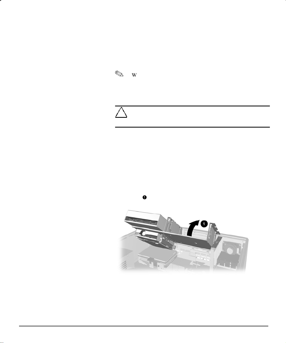
9. Gently rotate the drive cage back into the computer chassis.
10. Replace the access panel.
11. Reconfigure the computer, if necessary. Refer to the Computer
If you normally lock the Smart Cover Lock, use Computer Setup to
Installing a Hard Drive
CAUTION: When returning the drive cage to its normal position, use
extreme caution to prevent damaging the data and power cables.
Setup Guide for more information.
relock the lock and enable the Smart Cover Sensor.
CAUTION: To prevent loss of work and damage to the computer or
drive:
If you are inserting or removing a hard drive, turn off
the computer. Do not remove a hard drive while the
computer is on or in standby mode.
Before handling a drive, ensure that you are
discharged of static electricity. While handling a drive,
avoid touching the connector. For more information
about preventing electrostatic damage, refer to
Appendix E, “Electrostatic Discharge.”
Handle a drive carefully, do not drop it.
Do not use excessive force when inserting a drive.
Avoid exposing a hard drive to liquids, temperature
extremes, or products that have magnetic fields such
as monitors or speakers.
If a drive must be mailed, place the drive in a bubblepack mailer or other suitable protective packaging and
label the package “Fragile: Handle With Care.”
1. If you have locked the Smart Cover Lock, use Computer Setup to
unlock the lock and disable the Smart Cover Sensor.
2. Shut down the operating system properly, turn off the computer,
disconnect the power cord from the electrical outlet, and remove
the computer cover.
3. Rotate the drive cage to the upright position.
4. Install two guide screws on each side of the drive.
5. Pull the green release lever into its upright position.
Hardware Reference Guide 2-13
Page 22

6. Set the hard drive into the hard drive bay by placing the guide
screws toward the front of the drive into the slots in the drive
.
cage
7. Place the back of the hard drive down flat in the bay.
8. Push the green release lever down until it locks, securing the hard
drive in place
.
Refer to Appendix B, “Hard Drive Installation Guidelines,” for
more information.
2-14 Hardware Upgrades
Installing the Primary Hard Drive
Page 23

Installing the Secondary Hard Drive
Hardware Reference Guide 2-15
Page 24

Removing a CD-ROM Drive from the Drive Cage
1. If you have locked the Smart Cover Lock, use Computer Setup to
unlock the lock and disable the Smart Cover Sensor.
2. Shut down the operating system properly, turn off the computer,
disconnect the power cord from the electrical outlet, and remove
the computer cover.
3. Disconnect the drive power cable, signal cable, and audio
connector.
4. Press the drive release latch (labeled with an arrow) forward
5. At the same time, push the drive toward the back of the computer
, then lift it out of the drive cage .
.
2-16 Hardware Upgrades
Removing a CD-ROM Drive from the Drive Cage
6. Store the drive in antistatic packaging.
Page 25

Removing a Diskette Drive from the Drive Cage
1. If you have locked the Smart Cover Lock, use Computer Setup to
unlock the lock and disable the Smart Cover Sensor.
2. Shut down the operating system properly, turn off the computer,
disconnect the power cord from the electrical outlet, and remove
the computer cover.
3. Rotate the drive cage to its upright position.
4. Disconnect the drive power cable and signal cable.
5. Pull the green drive release latch to the right
6. Slide the drive out of the drive cage
Removing a Diskette Drive from the Drive Cage
7. Store the drive in antistatic packaging.
.
.
Hardware Reference Guide 2-17
Page 26

Removing a Hard Drive from the Drive Cage
1. If you have locked the Smart Cover Lock, use Computer Setup to
unlock the lock and disable the Smart Cover Sensor.
2. Shut down the operating system properly, turn off the computer,
disconnect the power cord from the electrical outlet, and remove
the computer cover.
3. Rotate the drive cage to its upright position.
4. Disconnect the drive power cable and signal cable.
5. Lift up to unlock the green drive release latch
6. Lift up the back of the hard drive and pull the drive out of the drive
cage
.
Removing the Primary Hard Drive from the Drive Cage
.
2-18 Hardware Upgrades
Page 27

Removing the Secondary Hard Drive from the Drive Cage
7. Store the drive in antistatic packaging.
Hardware Reference Guide 2-19
Page 28
Smart Cover Lock
Using the Smart Cover FailSafe Key
The Smart Cover Lock is a software-controllable cover lock. This lock
prevents unauthorized access to the internal components when the
Smart Cover Lock and setup password are enabled. Your computer
ships with the Smart Cover Lock in the unlocked position. For more
information about locking the Smart Cover Lock, refer to the Desktop
Management guide.
If you enable the Smart Cover Lock and cannot enter your password to
disable the lock, you will need a Smart Cover FailSafe Key to open the
computer cover. You will need the key in any of the following
circumstances:
Power outage
Startup failure
PC component (e.g., processor or power supply) failure
Forgotten password
CAUTION: The Smart Cover FailSafe Key is a specialized tool
available from Compaq. Be prepared; order this key before you need
one.
2-20 Hardware Upgrades
You can obtain the FailSafe Key by any one of the following methods:
Contact your authorized Compaq reseller or service provider.
Refer to the Compaq World Wide Web site (www.compaq.com)
for ordering information.
Call the appropriate number listed in the warranty.
Page 29

To open the computer cover:
1. Shut down the operating system properly, turn off the computer
and any external devices, then disconnect the power cord from the
electrical outlet.
2. Using the Smart Cover FailSafe Key, remove the top tamper-proof
screw, and loosen the bottom tamper-proof screw only enough to
allow the computer access panel to be removed.
Removing the Smart Cover Lock Screws
3. Remove the computer cover.
To reattach the Smart Cover Lock, secure the lock in place with the
tamper-proof screws.
Hardware Reference Guide 2-21
Page 30

appendix A
SPECIFICATIONS
Compaq Deskpro EN, Slim Desktop
Desktop Dimensions
Height
Width
Depth
Approximate Weight
Desktop Model 26.0 lb 12 kg
Weight Supported (maximum distributed load) 100.0 lb 45.5 kg
Temperature Range
Operating
Nonoperating
Relative Humidity (noncondensing)
Operating
Nonoperating
Maximum Altitude (unpressurized)
Operating
Nonoperating
Power Supply
Operating Voltage Range
Rated Voltage Range
Rated Line Frequency
Power Output 200 W 200 W
Rated Input Current (maximum) 6 A 3 A
Heat Dissipation
Maximum
Nominal
5.38 in
17.65 in
17.11 in
50° to 95°F
-4° to 140°F
20 to 80%
10 to 90%
10,000 ft
30,000 ft
90-132 VAC
100-127 VAC
50-60 Hz
1050 Btu/hr
525 Btu/hr
13.67 cm
44.83 cm
43.46 cm
10° to 35°C
-20° to 60°C
20 to 80%
10 to 90%
3048 m
9144 m
180-264 VAC
220-240 VAC
50-60 Hz
265 kg-cal/hr
133 kg-cal/hr
Hardware Reference Guide A-1
Page 31

appendix B
HARD DRIVE INSTALLATION GUIDELINES
Using the Cable-Select Feature with Ultra ATA Devices
Optional drives are available from Compaq in kits that include a special
drive cable. The configuration of the drives employs a cable-select
feature that identifies the drives as device 0 (primary drive) or device 1
(secondary drive). The computer recognizes device 0 as the drive
connected to the short segment of the drive cable (farthest from the
system board), and device 1 as the drive connected to the long segment
of the drive cable (closest to the system board).
When using an 80 conductor Ultra ATA cable, connect the colored
connectors as follows:
blue–system board (end)
gray–device 1 (middle)
black–device 0 (end)
Drive installation requires no jumper setting changes on the existing or
optional drives. All Compaq drives have the jumpers preset for cableselect installation.
If installing a second device on the primary controller, you
must use an 80 conductor Ultra ATA cable for optimal
performance. This cable is standard on select models.
Hardware Reference Guide B-1
Page 32

Installing SCSI Devices
Guidelines for Installing Optional SCSI Devices
Select models feature a Wide Ultra160 SCSI host adapter that supports
up to fifteen wide internal and external SCSI devices. Select models
come with an internal SCSI hard drive preinstalled. Additional highperformance SCSI devices can be added to these select models.
When installing additional SCSI devices, you must adhere to the
following guidelines:
The Wide Ultra160 SCSI host adapter supports up to 15 wide SCSI
devices.
Every SCSI device must have a unique identification (ID) number
(0 - 15). The SCSI host adapter identifies signals to and from a
SCSI device by its SCSI ID number rather than its location.
Moving a SCSI device from one position to another on the SCSI
chain does not affect the communication between the controller and
the SCSI device. The reserved and available SCSI ID numbers for
SCSI devices are as follows:
0 is reserved for the hard drive.
1 through 4 are available.
B-2 Hard Drive Installation Guidelines
5 is reserved for a CD-ROM drive.
6 is available.
7 is reserved for the SCSI host adapter.
8 - 15 are available.
Page 33

Every SCSI chain or circuit must be terminated (closed) at both
ends. Termination can be accomplished by using the terminating
feature on the device or by using a terminated cable.
Some devices may not have terminating jumpers on the device.
Termination on these devices must be achieved with terminated
cable.
Turn on an external SCSI device before turning on power to the
computer. This enables the system board controller to
recognize the external SCSI device and automatically reset.
When an external SCSI device is connected to the external
SCSI connector on the rear panel of the computer, that device
becomes the end of the SCSI chain and must be terminated.
The system accommodates a combination of internal and external
SCSI devices, such as SCSI tape, CD-ROM drives, and hard
drives.
When an IDE hard drive and SCSI hard drive are both
installed, the system can boot only from the IDE hard drive.
Before you can install a SCSI device, you must first verify the
SCSI ID of the device and, if necessary, set the SCSI ID to a
new number. Be sure that each SCSI device on the SCSI chain
has a unique SCSI ID number.
Second, you must determine if the device ought to have
termination enabled or disabled. Set the termination if
necessary.
Hardware Reference Guide B-3
Page 34

Cabling for Optional SCSI Devices
Depending on the model, your computer may include one of the SCSI
cables shown in the next illustration.
SCSI Cable Options
B-4 Hard Drive Installation Guidelines
Because your computer comes preconfigured, cable configuration does
not become a consideration until you decide to add an optional SCSI
device.
Computers with 2-, 3-, and 4-peripheral SCSI cables come
with a terminator
the opposite end of the cable always connects to the system
board. All SCSI devices connected with these cables must
have their termination disabled.
Some devices may not have terminating jumpers on the device.
Termination on these devices must be achieved with terminated
cable.
When installing a SCSI device, be sure to route the SCSI cable over
the expansion board cage, between the raised areas.
For additional information about installing optional SCSI devices,
refer to the documentation that comes with the device or contact your
Compaq authorized dealer, reseller, or service provider.
on the end of the cable. The connector on
Page 35

Using SCSISelect with SCSI Devices
The Wide Ultra160 SCSI host adapter includes the SCSISelect utility to
configure the host adapter and to run SCSI disk utilities. To run the
SCSISelect utility:
In Post Messages Enabled mode: Press Ctrl+A when the Press
<Ctrl><A> for SCSISelect Utility message appears during POST.
In Post Messages Disabled mode: When the Compaq logo screen
appears, press any key to exit the logo screen. Immediately after
exiting the logo screen, press Ctrl+A to access the SCSISelect
utility.
A menu appears with the following options:
Configure/View Host Adapter Settings
SCSI Bus Interface Definitions
– Host Adapter SCSI ID
– SCSI Parity Checking
– Host Adapter SCSI Termination
Additional Options
– Boot Device Options
– SCSI Device Configuration
– Advanced Configuration Options
SCSI Disk Utilities
Lists all SCSI devices and SCSI ID numbers
For information about configuring POST message display
status, refer to the Computer Setup guide.
Hardware Reference Guide B-5
Page 36

appendix C
BATTERY REPLACEMENT
The battery that comes with your computer provides power to the realtime clock and has a lifetime of about three years. When replacing the
battery, use an equivalent 3-volt lithium coin cell battery.
WARNING: Your computer contains an internal lithium
manganese dioxide, vanadium pentoxide, or alkaline battery or
battery pack. There is a risk of fire and burns if the battery pack
is not handled properly. To reduce the risk of personal injury:
Do not attempt to recharge the battery.
Do not expose to temperatures higher than 60°C (140ºF).
Do not disassemble, crush, puncture, short external contacts, or
dispose of in fire or water.
Replace only with the Compaq spare designated for this product.
Batteries, battery packs, and accumulators should not be
disposed of together with the general household waste. In order
to forward them to recycling or proper disposal, please use the
public collection system or return them to Compaq, your
authorized partners, or their agents.
1. If you have locked the Smart Cover Lock, use Computer Setup to
unlock the lock and disable the Smart Cover Sensor.
2. Shut down the operating system properly, turn off the computer
and any external devices, disconnect the power cord from the
electrical outlet, and remove the computer cover or access panel.
It may be necessary to remove an expansion card to gain access
to the battery.
Hardware Reference Guide C-1
Page 37

3. Locate the battery and battery holder on the system board, as
shown in the following illustration.
Battery and Battery Holder
4. Lift the battery out of its holder.
C-2 Battery Replacement
Removing the Coin Cell Battery
5. Slide the replacement battery into position, positive side up.
The battery holder automatically secures the battery in the proper
position.
Page 38

6. Replace the computer cover or access panel.
7. Plug in the computer and turn on power to the computer.
8. Reset the date and time, your passwords, and any special system
setups, using Compaq Computer Setup. Refer to the Computer
Setup guide.
If you normally lock the Smart Cover Lock, use Computer Setup to
relock the lock and enable the Smart Cover Sensor.
Hardware Reference Guide C-3
Page 39
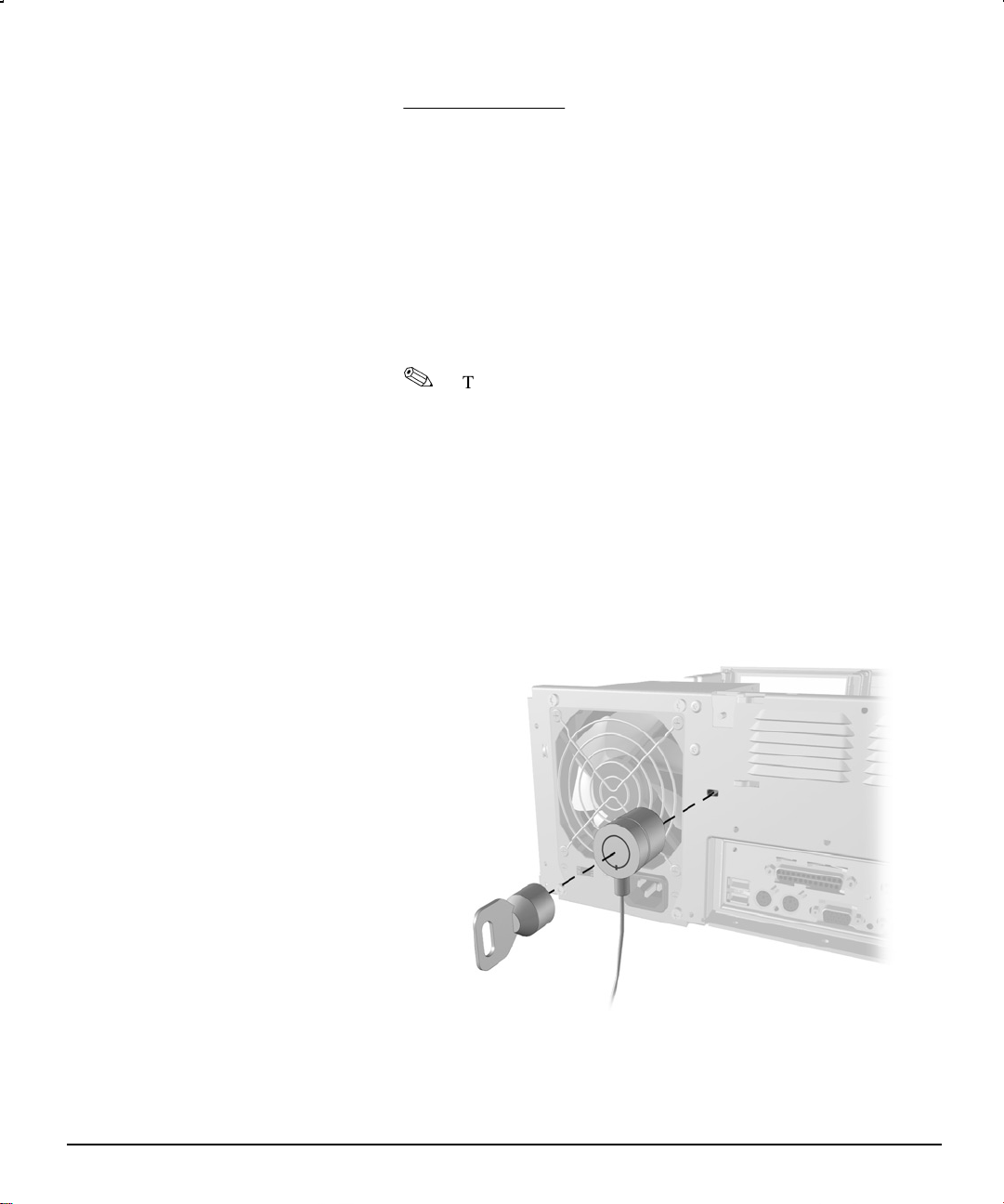
Installing a Cable Lock
appendix D
SECURITY LOCK PROVISIONS
Depending on the model, the rear panel of the computer accommodates
a cable lock so that the computer can be physically secured to a work
area.
1. Loop the cable around a heavy, fixed object to which you want to
2. Insert the cable lock end of the cable through the loop end of the
3. Insert the lock into the appropriate slot on the rear of the computer
The cable lock can be purchased from Kensington Microware
Limited or Compaq authorized dealers, resellers, and service
providers. Ask for the Kensington MicroSaver Security
System, Model 64068.
secure the computer.
cable.
and lock with the key.
Compaq Deskpro EN, Slim Desktop
Hardware Reference Guide D-1
Page 40

Compaq Deskpro EN, Convertible Minitower
Compaq Deskpro EN, Small Form Factor
D-2 Security Lock Provisions
Page 41

appendix E
ELECTROSTATIC DISCHARGE
A discharge of static electricity from a finger or other conductor may
damage system boards or other static-sensitive devices. This type of
damage may reduce the life expectancy of the device.
Preventing Electrostatic Damage
To prevent electrostatic damage, observe the following precautions:
Avoid hand contact by transporting and storing products in staticsafe containers.
Keep electrostatic-sensitive parts in their containers until they
arrive at static-free workstations.
Place parts on a grounded surface before removing them from their
containers.
Avoid touching pins, leads, or circuitry.
Always be properly grounded when touching a static-sensitive
component or assembly.
Hardware Reference Guide E-1
Page 42

Grounding Methods
There are several methods for grounding. Use one or more of the
following methods when handling or installing electrostatic-sensitive
parts:
Use a wrist strap connected by a ground cord to a grounded
workstation or computer chassis. Wrist straps are flexible straps
with a minimum of 1 Mohm +/- 10 percent resistance in the ground
cords. To provide proper ground, wear the strap snug against the
skin.
Use heelstraps, toestraps, or bootstraps at standing workstations.
Wear the straps on both feet when standing on conductive floors or
dissipating floor mats.
Use conductive field service tools.
Use a portable field service kit with a folding static-dissipating
work mat.
If you do not have any of the suggested equipment for proper
grounding, contact your Compaq authorized dealer, reseller, or service
provider.
For more information on static electricity, contact your
Compaq authorized dealer, reseller, or service provider.
E-2 Electrostatic Discharge
Page 43

Routine Computer Care
appendix F
ROUTINE COMPUTER CARE AND SHIPPING PREPARATION
Follow these suggestions to take care of your computer and monitor:
Operate the computer on a sturdy, level surface. Leave a 3-inch
(7.6-cm) clearance at the back of the system unit and above the
monitor to permit the required airflow.
Never operate the computer with the cover or side panel removed.
Never restrict the airflow into the computer by blocking the front
vents or air intake. Do not place the keyboard, with the keyboard
feet down, directly against the front of the desktop unit as this also
restricts airflow.
Keep the computer away from excessive moisture, direct sunlight,
and extremes of heat and cold. For information about the
recommended temperature and humidity ranges for your computer,
refer to Appendix A, “Specifications,” in this guide.
Keep liquids away from the computer and keyboard.
Never cover the ventilation slots on the monitor with any type of
material.
Hardware Reference Guide F-1
Page 44

CD-ROM Drive Precautions
Be sure to observe the following guidelines while operating or cleaning
your CD-ROM drive.
Operation
Turn off the computer before you do either of the following:
Wipe the exterior of the computer with a soft, damp cloth as
needed. Using cleaning products may discolor or damage the
finish.
Occasionally clean the air vents on the front and back of the
computer. Lint and other foreign matter can block the vents
and limit the airflow.
Do not move the drive during operation. This may cause it to
malfunction during reading.
Avoid exposing the drive to sudden changes in temperature, as
condensation may form inside the unit. If the temperature suddenly
changes while the drive is on, wait at least one hour before you turn
off the power. If you operate the unit immediately, it may
malfunction while reading.
Cleaning
Safety
If any object or liquid falls into the drive, immediately unplug the
computer and have it checked by an authorized Compaq service
provider.
F-2 Routine Computer Care and Shipping Preparation
Avoid placing the drive in a location that is subject to high
humidity, extreme temperatures, mechanical vibration, or direct
sunlight.
Clean the panel and controls with a soft, dry cloth or a soft cloth
lightly moistened with a mild detergent solution. Never spray
cleaning fluids directly on the unit.
Avoid using any type of solvent, such as alcohol or benzene, which
may damage the finish.
Page 45

Shipping Preparation
Follow these suggestions when preparing to ship your computer:
1. Back up the hard drive files onto PD discs, tape cartridges, or
diskettes. Be sure that the backup media is not exposed to electrical
or magnetic impulses while stored or in transit.
2. Remove and store any program diskettes from the diskette drives.
3. Insert a blank diskette into the diskette drive to protect the drive
4. Turn off the computer and external devices.
5. Disconnect the power cord from the electrical outlet, then from the
6. Disconnect the system components and external devices from their
7. Pack the system components and external devices in their original
The hard drive locks automatically when the system power is
turned off.
while in transit. Do not use a diskette on which you have stored or
plan to store data.
computer.
power sources, then from the computer.
Ensure that all boards are seated properly and secured in the
board slots before shipping the computer.
packing boxes or similar packaging with sufficient packing
material to protect them.
For environmental nonoperating ranges, refer to Appendix A,
“Specifications,” in this guide.
Hardware Reference Guide F-3
Page 46

INDEX
A
audio, 2-4
B
bezel blanks, removing, 2-10
C
CD-ROM drive, 2-4
installing, 2-11
computer access panel, removing,
2-1
configuration label, 2-2
cover
key, 2-20
removing, 2-1
D
DIMMs (dual inline memory
modules)
installing, 2-5
diskette drive, 2-4
drive
bays, 2-4
bezel, removing, 2-10
cage, 2-3
installing optional, 2-10
installing optional 5.25-inch,
2-11
dual inline memory modules
(DIMMs)
installing, 2-5
DVD-ROM drive, installing, 2-11
E
expansion card
installing, 2-8
expansion slot cover, removing,
2-7
expansion slots, 2-7
G
graphics controller, 2-4
H
hard drive, 2-4
I
installation sequence, 1-1
internal components, 2-4
M
memory
installing additional, 2-5
O
optional equipment
adding or removing, 1-3
P
Plug and Play, 1-3
power supply, 2-4
processor, 2-4
R
rotating drive cage, 2-3
Hardware Reference Guide I-1
Page 47

S
screws, 2-10
security
Smart Cover Lock, 2-4, 2-20
Smart Cover Sensor, 2-4
slot cover, expansion, 2-7
slots, expansion, 2-7
Smart Cover FailSafe Key, 2-20
Smart Cover Lock, 2-4, 2-20
Smart Cover Sensor, 2-4
speaker, 2-4
system configuration, 1-3
T
tape drive, installing, 2-11
I-2 Index
Page 48

178171-002
 Loading...