

Page 1
INSTALLATION AND OPERATION MANUAL
CNGE4US
10/100/1000 MBPS 4 PORT ETHERNET
UNMANAGED SWITCH
The ComNet™ CNGE4US Ethernet 4 port unmanaged switches are designed to
transmit and receive 10/100/1000 Mbps data using small form factor pluggable
modules. Both are environmentally hardened to operate in demanding
environments. LED indicators are provided for confirming equipment operating
status. Plug-and-play design ensures ease of installation requiring no optical
adjustments. Packaged in the exclusive ComNet ComFit housing, these units
may be either wall or rack-mounted, or may be DIN-rail mounted by the
addition of ComNet model DINBKT1 adaptor plate.
See Figure A for mounting instructions.
INS_CNGE4US_REV–
07/22/09
PAGE 1
Page 2
INSTALLATION AND OPERATION MANUAL CNGE4US
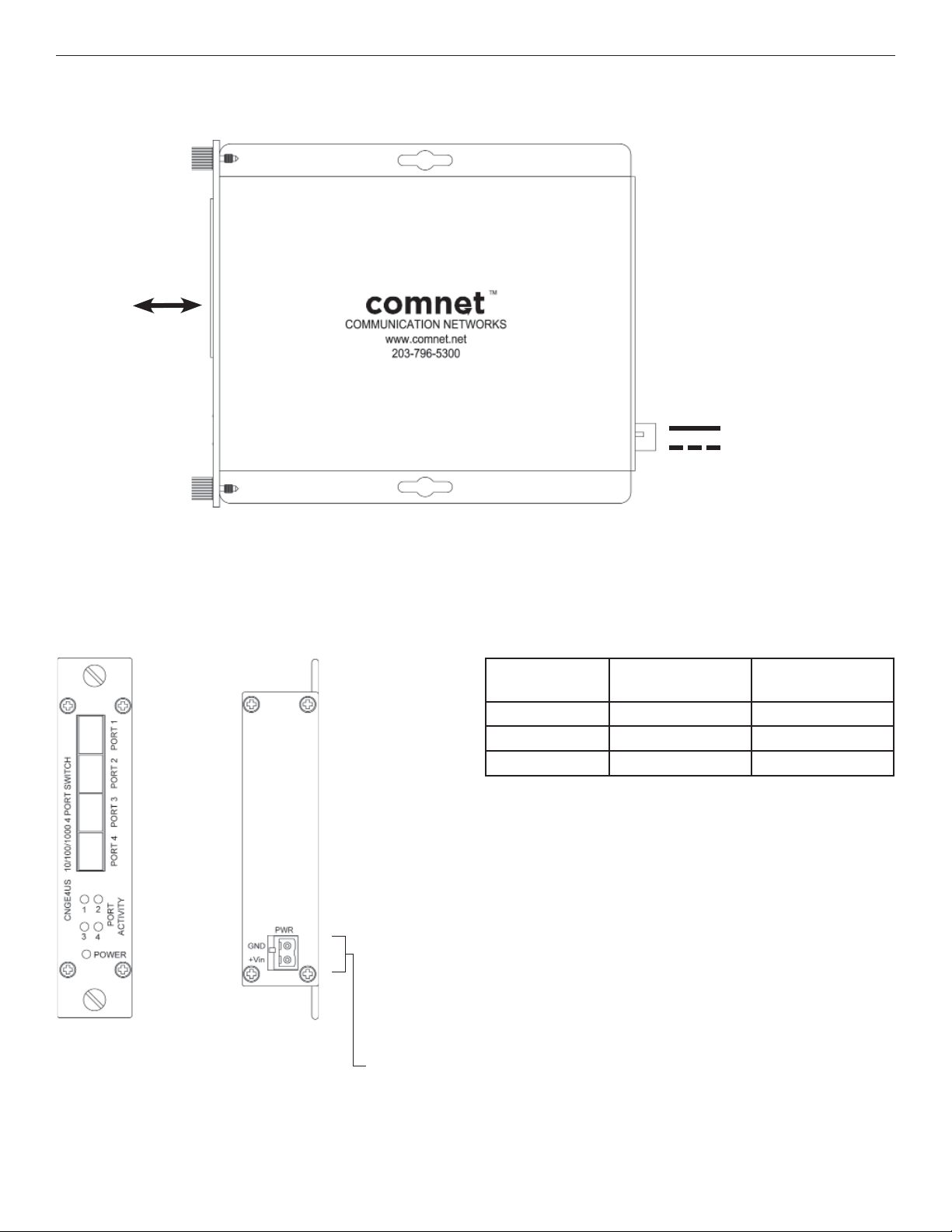
FIGURE 1 – CNGE4US UNMANAGED SWITCH
UP TO 4
CONNECTIONS
AS DETERMINED
BY SELECTION OF
SFP MODULES
BLACK
BLACK WITH
WHITE STRIPE
FIGURE 2 – CNGE4US
REAR PANELFRONT PANEL
Power Supply:
8-24 VDC @ 700 mA
FIGURE 3 – LED INDICATORS
PORT ACTIVITY
(1 – 4)
SOLID
BLINKING
OFF
No Activity Unit powered up
Activity –
No Link Unit Powered Down
POWER
TECH SUPPORT: 1.888.678.9427
NOTE: Remove Electrical Connector for Rack Mount Units
INS_CNGE4US_REV–
07/22/09
PAGE 2
Page 3

MECHANICAL INSTALLATION INSTRUCTIONS
INSTALLATION CONSIDERATIONS
This fiber-optic link is supplied as a Standalone/Rack module. Units
should be installed in dry locations protected from extremes of
temperature and humidity.
C1-US, C1-EU, C1-AU OR C1-CH CARD CAGE RACKS
CAUTION: Although the units are hot-swappable and may be installed
without turning power off to the rack, ComNet recommends that
the power supply be turned off and that the rack power supply
is disconnected from any power source. Note: Remove electrical
connector before installing in card cage rack.
1. Make sure that the card is oriented right side up, and slide it into
the card guides in the rack until the edge connector at the back
of the card seats in the corresponding slot in the rack’s connector
panel. Seating may require thumb pressure on the top and bottom
of the card’s front panel.
CAUTION: Take care not to press on any of the LEDs.
2. Tighten the two thumb screws on the card until the front panel of
the card is seated against the front of the rack.
WARNING: Unit is to be used with a Listed Class 2 or LPS power supply rated
8-24 VDC @ 700mA.
FIGURE A
Dimensions are for a standard ComNet one slot module
.156 [3.96 mm]
.313 [7.95 mm]
IMPORTANT SAFEGUARDS:
A) Elevated Operating Ambient - If installed in a closed or multi-unit rack
assembly, the operating ambient temperature of the rack environment may
be greater than room ambient. Therefore, consideration should be given to
installing the equipment in an environment compatible with the maximum
ambient temperature (Tma) specified by the manufacturer.
B) Reduced Air Flow - Installation of the equipment in a rack should be such
that the amount of air flow required for safe operation of the equipment is
not compromised.
3 CORPORATE DRIVE | DANBURY, CT 06810 | USA
T: 203.796.5300 | F: 203.796.5303 | TECH SUPPORT: 1.888.678.9427 | INFO@COMNET.NET
8 TURNBERRY PARK ROAD | GILDERSOME | MORLEY | LEEDS, UK LS27 7LE
T: +44 (0)113 307 6400 | F: +44 (0)113 253 7462 | INFO-EUROPE@COMNET.NET
© 2011 Communications Networks Corporation. All Rights Reserved. “ComNet” and the “ComNet Logo” are registered trademarks of Communication Networks, LLC.
INS_CNGE4US_REV–
07/22/09
PAGE 3
 Loading...