

Page 1
INSTALLATION AND OPERATION MANUAL
CNGE24FX12TX12MS[POE]
Industrial Grade Managed Ethernet Switch w/
12 × 100/1000Base-FX + 12 × 10/100/1000Base-TX Ports
w/ Optional 30W PoE
This guide serves the following
ComNet Model Numbers:
CNGE24FX12TX12MS
CNGE24FX12TX12MSPOE
The ComNet CNGE24FX12TX12MS[POE] has twelve 100/1000Base-FX SFP* ports
and twelve 10/100/1000Base-TX ports. All SFP ports utilize ComNet SFP modules
for fiber and connector type and distance. The IEEE802.3-compliant unit offers
multiple Ethernet redundancy protocols (MSTP/RSTP/STP/ERPS (G.8032)) which
protect your applications from network interruptions or temporary malfunctions by
redirecting transmission within the network. The switch provides advanced IP-based
management that can limit the maximum bandwidth for each connected IP device,
allowing the user to adjust usage. Application-based QoS can set a higher priority
for data streaming. The Device-Binding function can prevent unauthorized network
access, increasing security.
The CNGE24FX12TX12MSPOE models provide twelve electrical ports supporting up to
thirty watts of power. All PoE ports are IEEE 802.3at compliant.
Each model is provided with redundant power inputs which can be either one mains
voltage and one or two low voltage DC inputs or two low voltage DC inputs.
Rev. 2.22.18
Page 2

INSTRUCTION MANUAL CNGE24FX12TX12MS[POE]
Contents
Regulatory Compliance Statement 6
Warranty 6
Disclaimer 6
Safety Information 7
Hardware Installation 8
Rack mount kit assembly 8
Hardware Overview 9
Power Supply 10
Front Panel LEDs 10
WEB Management 11
Login 11
Configuration 15
Green Ethernet 23
Thermal Protection 25
DHCP 28
DHCP Pool Configuration 31
Security 36
Network 54
Screen 57
Aggregation 84
Loop Protection 86
Spanning Tree 87
IPMC Profile 94
MVR 97
IPMC 99
LLDP 107
TECH SUPPORT: 1.888.678.9427
PoE 109
EP S 111
Ethernet Protection Switch Configuration 112
Ethernet Ring Protection Switch Configuration 129
MAC Table 132
INS_CNGE24FX12TX12MS[POE] Rev. 2.22.18 PAGE 2
Page 3

INSTRUCTION MANUAL CNGE24FX12TX12MS[POE]
VLAN Translation 133
VLANs 135
Private VLANs 138
VCL 140
Protocol-based VLAN 141
Voice VLAN 145
Mirroring & Remote Mirroring Configuration 166
UPnP 169
GVRP 170
Monitor Menu 172
Sys te m 172
CUP Load 173
System IP Status 174
System Log 175
Port State 177
Green Ethernet 178
Thermal Protection 179
Por t s 179
QoS Statistics 180
DHCP 184
Security 190
AAA 198
Aggregation Status 204
LACP 205
Loop Protection 207
MVR 212
IPMC 215
LLDP 221
PoE 226
Diagnostics Menu 231
TECH SUPPORT: 1.888.678.9427
MAC Table 227
VLANs 228
Ping 231
Ping6 232
PHYtest 233
INS_CNGE24FX12TX12MS[POE] Rev. 2.22.18 PAGE 3
Page 4

INSTRUCTION MANUAL CNGE24FX12TX12MS[POE]
Maintenance Menu 234
Restart Device 234
Factory Defaults 234
Software 235
Configuration 237
Using Switch CLI 240
About CLI Management 240
CLI Management by RS-232 Serial Console 240
CLI Management by Telnet 243
Commander Groups 244
Quick Start 245
Log In and Reset Configuration to Factory Default 245
Set Device Hostname and Admin User Password 246
Set VLAN 1 IP Address 246
Display and Save Configuration to Flash 248
ICLI Basics 250
Command Structure and Syntax 251
Syntax 252
Ethernet Interface Naming 254
Using the Keyboard 256
Basic Line Editing 256
Command History 257
Context-Sensitive Help 259
Using Context-Sensitive Help 259
Long Lines and Pagination 261
Other Special Keys 262
Filtering Output 262
Understanding Modes and Sub-Modes 263
Using ‘do’ While in a Sub-Mode 266
TECH SUPPORT: 1.888.678.9427
Changing Between ICLI Modes 267
Understanding Privilege Levels 268
Configuring Privilege Level Passwords 269
Understanding Terminal Parameters 270
Changing Terminal Parameters 271
INS_CNGE24FX12TX12MS[POE] Rev. 2.22.18 PAGE 4
Page 5

INSTRUCTION MANUAL CNGE24FX12TX12MS[POE]
Using Banners 273
Configuring Banners 273
Configuring the System 275
Configuration Example 275
Resetting or Removing Condiguration with “no” 277
Using “no” Forms 277
Managing Users 278
Adding, Modifying, and Deletion Users 278
Using Show Commands 279
Listing All Show Commands 280
Show running-config 283
Default vs. Non-default vs. All Defaults 283
Show running-config [all-defaults] 285
Show running-config feature feature_name [all-defaults] 285
Show running-config interface list [all-defaults] 286
Working with Configuration Files 287
Reverting to Default Configuration 288
Working with Configuration Files 289
Using Reload Commands 291
Working with Software Images 292
Appendix A 293
Ethernet Ring Protection Switching Example Configuration 293
Configuring ERPS from the Web GUI 294
Ethernet Ring Protection Switching Configuration 301
Configuring ERPS from the ICLI 306
TECH SUPPORT: 1.888.678.9427
INS_CNGE24FX12TX12MS[POE] Rev. 2.22.18 PAGE 5
Page 6

INSTRUCTION MANUAL CNGE24FX12TX12MS[POE]
Regulatory Compliance Statement
Product(s) associated with this publication complies/comply with all applicable regulations. Please
refer to the Technical Specifications section for more details.
Warranty
ComNet warrants that all ComNet products are free from defects in material and workmanship
for a specified warranty period from the invoice date for the life of the installation. ComNet will
repair or replace products found by ComNet to be defective within this warranty period, with
shipment expenses apportioned by ComNet and the distributor. This warranty does not cover
product modifications or repairs done by persons other than ComNet-approved personnel, and
this warranty does not apply to ComNet products that are misused, abused, improperly installed,
or damaged by accidents.
Please refer to the Technical Specifications section for the actual warranty period(s) of the
product(s) associated with this publication.
Disclaimer
Information in this publication is intended to be accurate. ComNet shall not be responsible for its
use or infringements on third-parties as a result of its use. There may occasionally be unintentional
errors on this publication. ComNet reserves the right to revise the contents of this publication
without notice.
TECH SUPPORT: 1.888.678.9427
INS_CNGE24FX12TX12MS[POE] Rev. 2.22.18 PAGE 6
Page 7

INSTRUCTION MANUAL CNGE24FX12TX12MS[POE]
Safety Information
» Only ComNet service personnel can service the equipment. Please contact ComNet Technical
Support.
» The equipment should be installed in locations with controlled access, or other means of
security, and controlled by persons of authority. When operating at temperatures above 51º C, the
equipment surfaces will be hot to the touch. Installation in restricted access location is required
for this case.
» For POE models requiring a power supply not labeled LPS, the unit should be installed in a
restricted access location using a 60950-1, 2nd Edition + Am. 1 + Am. 2 Certified power supply
rated for the ambient temperature in which it is installed. Total derated power rating should be
greater than the sum of the attached loads plus 30 W for the switch.
» Use CDRH compliant SFP modules when using fiber connectivity with this device.
» When used in Australia or New Zealand, the product is certified for intra building applications
only, and should not be directly connected to network cables with outside plant routing.
TECH SUPPORT: 1.888.678.9427
INS_CNGE24FX12TX12MS[POE] Rev. 2.22.18 PAGE 7
Page 8

INSTRUCTION MANUAL CNGE24FX12TX12MS[POE]
Hardware Installation
Rack mount kit assembly
You can find the rack mount kit and the screws in the packing box. Please assembly the rack
mount kit on the switch with screws as shown below:
TECH SUPPORT: 1.888.678.9427
INS_CNGE24FX12TX12MS[POE] Rev. 2.22.18 PAGE 8
Page 9
INSTRUCTION MANUAL CNGE24FX12TX12MS[POE]
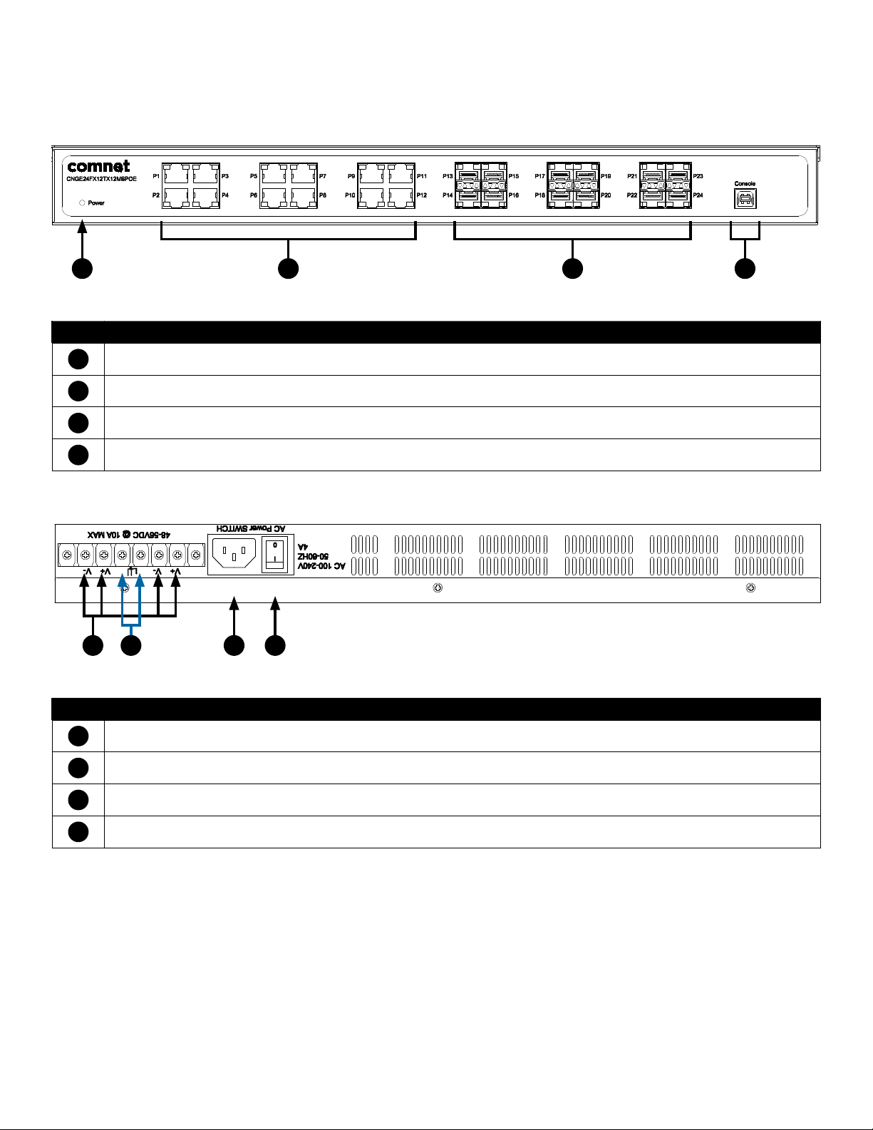
Hardware Overview
1 2 3 4
CNGE24FX12TX12MS[POE] Front Panel
Call-out Description
1
Status LED
2
12 × 10/100/1000Base-TX RJ45 Ports
3
12 × 100/1000Base-FX SFP Ports
4
USB Console Port
Call-out Description
1
1 × Mains Power Switch
2
1 × 90-240 VAC Mains Power Input
3
2 × 6-14 VDC or 48-57 VDC (model dependent) Redundant Power Input 2-Pin Terminal Block Connector
4
Fault Relay 2-Pin Terminal Block Connector
123 4
CNGE24FX12TX12MS[POE] Rear Panel
TECH SUPPORT: 1.888.678.9427
INS_CNGE24FX12TX12MS[POE] Rev. 2.22.18 PAGE 9
Page 10

INSTRUCTION MANUAL CNGE24FX12TX12MS[POE]
Power Supply
For CNGE24FX12TX12MS Models, Power Supply must be 6 to 14 VDC @ 30 W max or 90-240 VAC
mains.
For CNGE24FX12TX12MSPOE Model, Power Supply must be 48 to 57 VDC @ 390 W max or
90-240 VAC mains.
IMPORTANT SAFEGUARDS:
A) Elevated Operating Ambient - If installed in a closed or multi-unit rack assembly, the operating
ambient temperature of the rack environment may be greater than room ambient. Therefore,
consideration should be given to installing the equipment in an environment compatible with
the maximum ambient temperature (T
B) Reduced Air Flow - Installation of the equipment in a rack should be such that the amount of air
flow required for safe operation of the equipment is not compromised.
) specified by the manufacturer.
ma
Front Panel LEDs
LED Color Status Description
Status Green On Switch is operational
Gigabit Ethernet ports
Link Amber On Port in Full Duplex mode
Activity Green Blinking Data transmitted
Gigabit SFP ports
Link/Activity Green Blinking Data transmitted
TECH SUPPORT: 1.888.678.9427
INS_CNGE24FX12TX12MS[POE] Rev. 2.22.18 PAGE 10
Page 11
INSTRUCTION MANUAL CNGE24FX12TX12MS[POE]
WEB Management
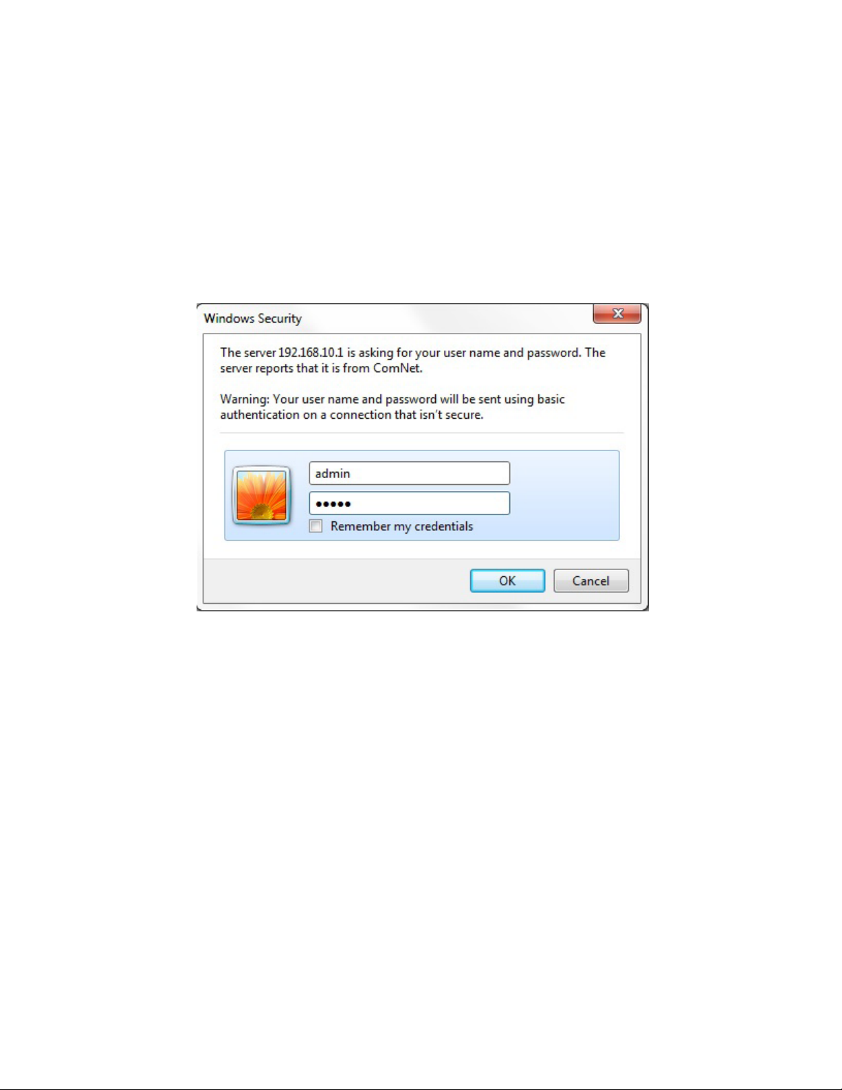
Login
Open a web browser and navigate to the switch using http:// and the IP address of the switch.
The default IP address is 192.168.10.1
This is the main login page. Default user name is “admin” with maximum length 32 Default
password is “admin” with maximum length 32.
Warning – Any changes made to the settings will apply only to the current running configuration
of the switch and will be lost in the event of a power cycle.
To save any changes made to persistent memory please go to "Maintenance ¦
Configuration ¦ Save startup-config" to write the changes to the switches startup
configuration.
TECH SUPPORT: 1.888.678.9427
INS_CNGE24FX12TX12MS[POE] Rev. 2.22.18 PAGE 11
Page 12
INSTRUCTION MANUAL CNGE24FX12TX12MS[POE]
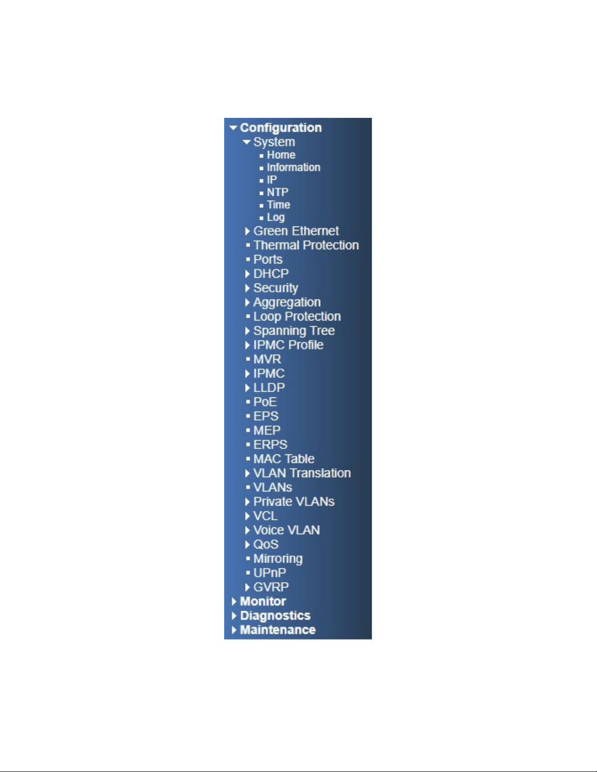
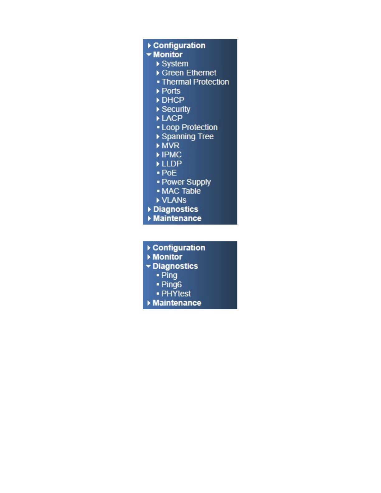
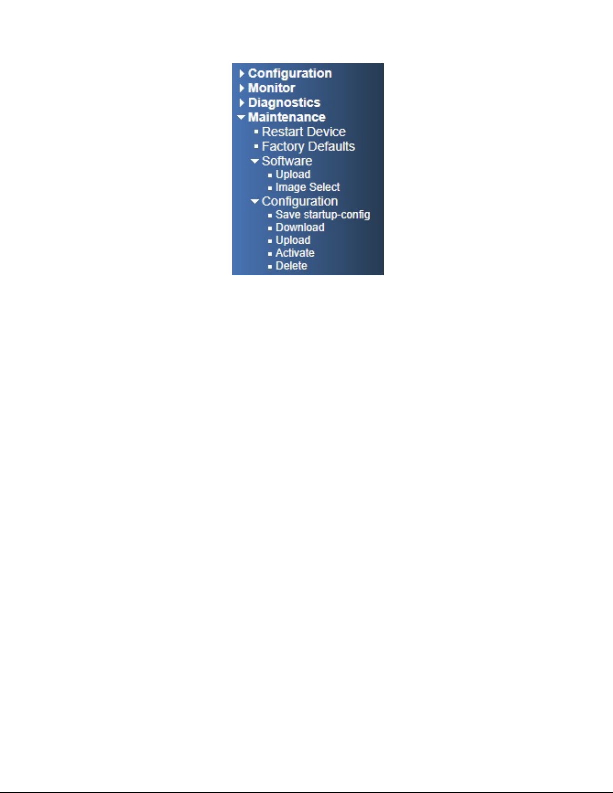
Menu Trees
The following tree views show the available menus within the switch web GUI. It offers the user
quick access to all the configuration settings within the switch.
TECH SUPPORT: 1.888.678.9427
Configuration Menu
INS_CNGE24FX12TX12MS[POE] Rev. 2.22.18 PAGE 12
Page 13
INSTRUCTION MANUAL CNGE24FX12TX12MS[POE]
Monitor Menu
Diagnostics Menu
TECH SUPPORT: 1.888.678.9427
INS_CNGE24FX12TX12MS[POE] Rev. 2.22.18 PAGE 13
Page 14
INSTRUCTION MANUAL CNGE24FX12TX12MS[POE]
Maintenance Menu
TECH SUPPORT: 1.888.678.9427
INS_CNGE24FX12TX12MS[POE] Rev. 2.22.18 PAGE 14
Page 15
INSTRUCTION MANUAL CNGE24FX12TX12MS[POE]
Configuration
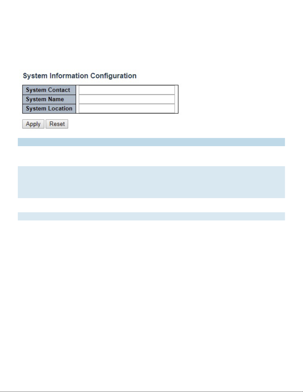
System Information
The switch system information is provided here.
Object Description
System Contact The textual identification of the contact person for this managed node, together with
information on how to contact this person. The allowed string length is 0 to 255, and the allowed
content is the ASCII characters from 32 to 126.
System Name An administratively assigned name for this managed node. By convention, this is the node’s fully-
qualified domain name. A domain name is a text string drawn from the alphabet (A-Za-z), digits
(0-9), minus sign (-). No space characters are permitted as part of a name. The first character
must be an alpha character. And the first or last character must not be a minus sign. The allowed
string length is 0 to 255.
System Location The physical location of this node (e.g., telephone closet, 3rd floor). The allowed string length is
0 to 255, and the allowed content is the ASCII characters from 32 to 126.
Apply Click to apply changes without saving. *
Reset Click to revert to previous values.
Save to startup-config is under Maintenance Menu tree.
TECH SUPPORT: 1.888.678.9427
INS_CNGE24FX12TX12MS[POE] Rev. 2.22.18 PAGE 15
Page 16
INSTRUCTION MANUAL CNGE24FX12TX12MS[POE]
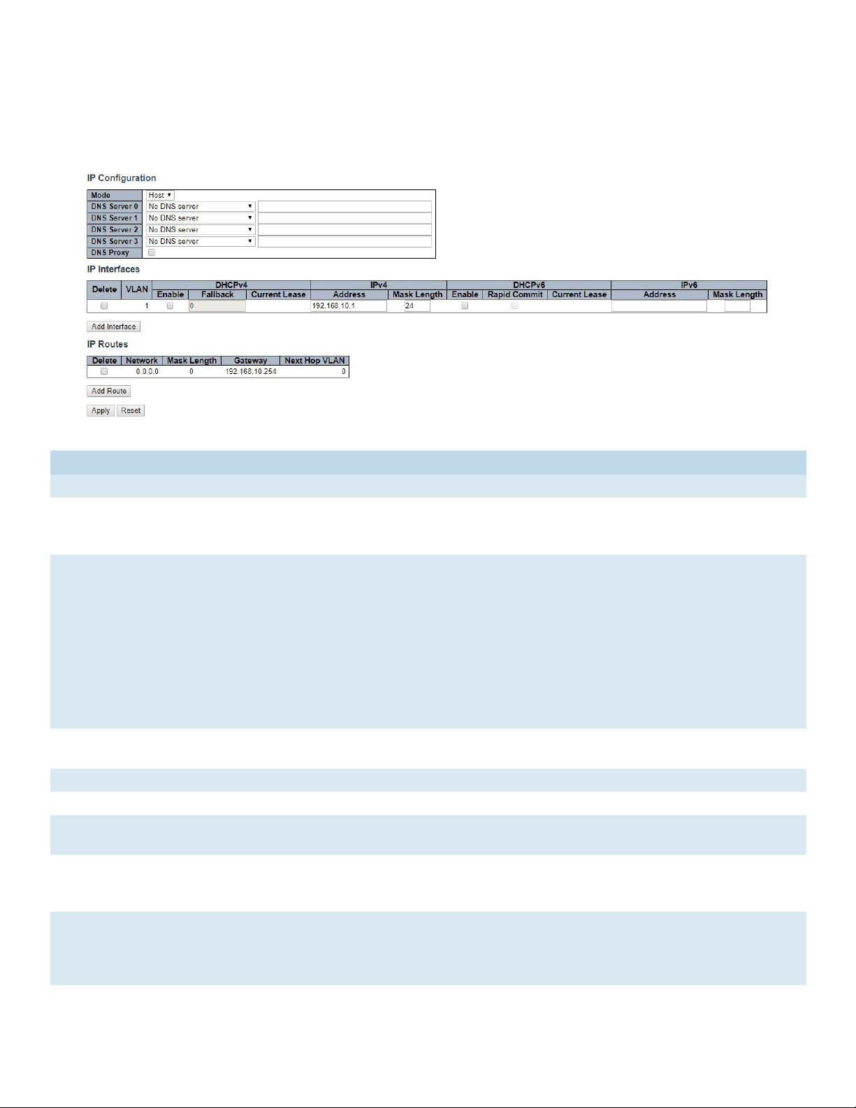
System IP
Configure IP basic settings, control IP interfaces and IP routes. The maximum number of interfaces
supported is 8 and the maximum number of routes is 32.
Object Description
IP Configuration
Mode Configure whether the IP stack should act as a Host or a Router. In Host mode, IP traffic
between interfaces will not be routed. In Router mode traffic is routed between all
interfaces.
DNS Server This setting controls the DNS name resolution done by the switch. The following modes are
supported:
• From any DHCP interfaces
The first DNS server offered from a DHCP lease to a DHCP-enabled interface will be used.
• No DNS server
No DNS server will be used.
• Configured
Explicitly provide the IP address of the DNS Server in dotted decimal notation.
• From this DHCP interface
Specify from which DHCP-enabled interface a provided DNS server should be preferred.
DNS Proxy When DNS proxy is enabled, system will relay DNS requests to the currently configured
DNS server, and reply as a DNS resolver to the client devices on the network.
IP Interfaces
Delete Select this option to delete an existing IP interface.
VLAN The VLAN associated with the IP interface. Only ports in this VLAN will be able to access the
IP interface. This field is only available for input when creating a new interface.
IPv4 DHCP Enabled Enable the DHCP client by checking this box. If this option is enabled, the system will
configure the IPv4 address and mask of the interface using the DHCP protocol. The DHCP
client will announce the configured System Name as hostname to provide DNS lookup.
IPv4 DHCP Fallback
Timeout
The number of seconds for trying to obtain a DHCP lease. After this period expires, a
configured IPv4 address will be used as IPv4 interface address. A value of zero disables the
fallback mechanism, such that DHCP will keep retrying until a valid lease is obtained. Legal
values are 0 to 4294967295 seconds.
TECH SUPPORT: 1.888.678.9427
INS_CNGE24FX12TX12MS[POE] Rev. 2.22.18 PAGE 16
Page 17

INSTRUCTION MANUAL CNGE24FX12TX12MS[POE]
Object Description
IPv4 DHCP Current
Lease
IPv4 Address The IPv4 address of the interface in dotted decimal notation.
IPv4 Mask The IPv4 network mask, in number of bits (prefix length). Valid values are between 0 and
DHCPv6 Enable Enable the DHCPv6 client by checking this box. If this option is enabled, the system will
DHCPv6 Rapid Commit Enable the DHCPv6 Rapid-Commit option by checking this box. If this option is enabled,
DHCPv6 Current Lease For DHCPv6 interface with an active lease, this column shows the interface address
IPv6 Address The IPv6 address of the interface. An IPv6 address is in 128-bit records represented as eight
IPv6 Mask The IPv6 network mask, in number of bits (prefix length). Valid values are between 1 and
Default Gateway
Address The IP address of the gateway valid format is dotted decimal notation.
IP Routes
Delete Select this option to delete an existing IP route.
Network The destination IP network or host address of this route. Valid format is notation or a valid
Mask Length The destination IP network or host mask, in number of bits (prefix length). It defines how
Gateway The IP address of the IP gateway. Valid format is notation or a valid IPv6 notation. Gateway
Next Hop VLAN
(Only for IPv6)
Add Interface Click to add a new IP Interface. A maximum of 8 interfaces is supported.
Add Route Click to add a new IP route. A maximum of 32 routes is supported.
For DHCP interfaces with an active lease, this column shows the current interface address,
as provided by the DHCP server.
If DHCP is enabled, this field configures the fallback address. The field may be left blank if
IPv4 operation on the interface is not desired - or no DHCP fallback address is desired.
30 bits for an IPv4 address.If DHCP is enabled, this field configures the fallback address
network mask. The field may be left blank if IPv4 operation on the interface is not desired or no DHCP fallback address is desired.
configure the IPv6 address of the interface using the DHCPv6 protocol.
the DHCPv6 client terminates the waiting process as soon as a Reply message with a Rapid
Commit option is received. This option is only manageable when DHCPv6 client is enabled.
provided by the DHCPv6 server.
fields of up to four hexadecimal digits with a colon separating each field (:). For example,
fe80::215:c5ff:fe03:4dc7. The symbol :: is a special syntax that can be used as a shorthand
way of representing multiple 16-bit groups of contiguous zeros; but it can appear only once.
It can also represent a legally valid IPv4 address. For example, ::192.1.2.34.
The field may be left blank if IPv6 operation on the interface is not desired.
128 bits for an IPv6 address.
The field may be left blank if IPv6 operation on the interface is not desired.
IPv6 notation. A default route can use the value 0.0.0.0or IPv6 :: notation.
much of a network address that must match, in order to qualify for this route. Valid values
are between 0 and 32 bits respectively 128 for IPv6 routes. Only a default route will have a
mask length of 0 (as it will match anything).
and Network must be of the same type.
The VLAN ID (VID) of the specific IPv6 interface associated with the gateway. The given VID
ranges from 1 to 4094 and will be effective only when the corresponding IPv6 interface is
valid.
If the IPv6 gateway address is link-local, it must specify the next hop VLAN for the gateway.
If the IPv6 gateway address is not link-local, system ignores the next hop VLAN for the
gateway.
TECH SUPPORT: 1.888.678.9427
INS_CNGE24FX12TX12MS[POE] Rev. 2.22.18 PAGE 17
Page 18

INSTRUCTION MANUAL CNGE24FX12TX12MS[POE]
Object Description
Apply Click to apply changes.
Reset Click to revert to previous values.
TECH SUPPORT: 1.888.678.9427
INS_CNGE24FX12TX12MS[POE] Rev. 2.22.18 PAGE 18
Page 19
INSTRUCTION MANUAL CNGE24FX12TX12MS[POE]
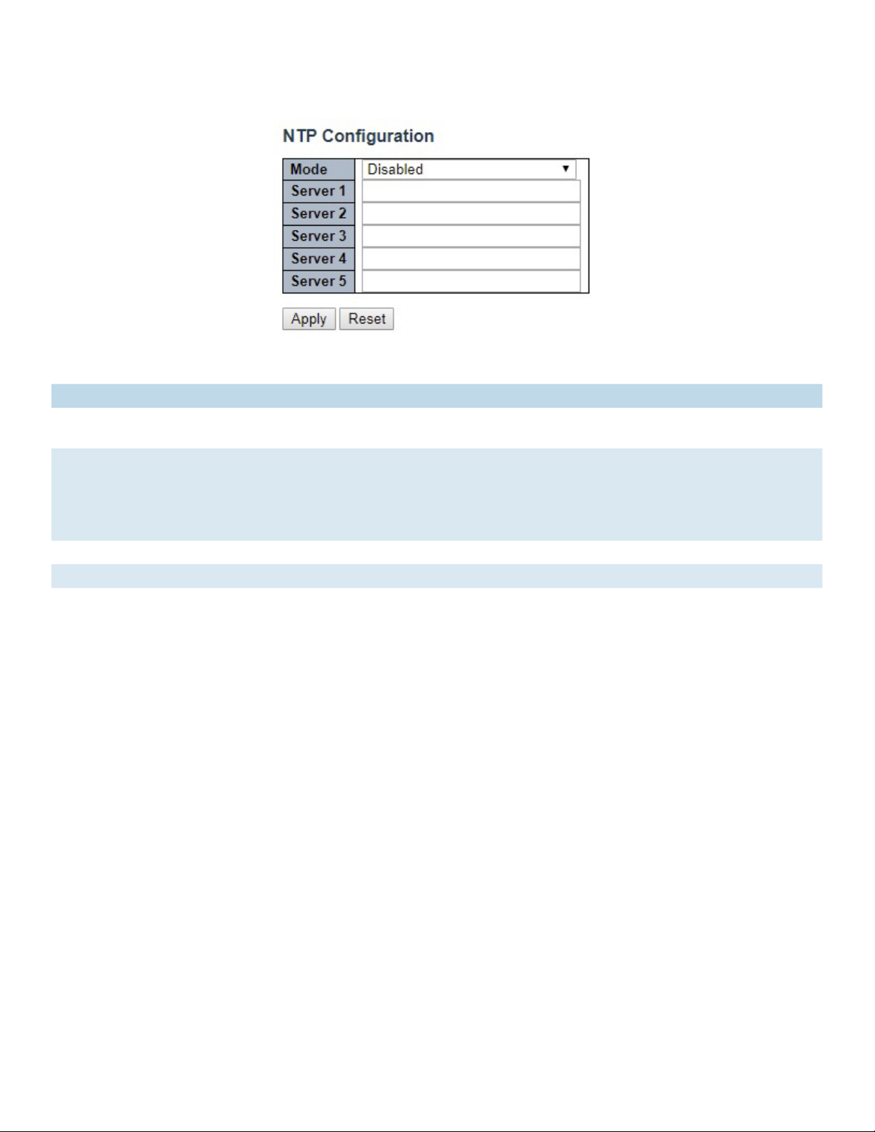
System NTP
Configure NTP on this page.
Object Description
Mode Indicates the NTP mode operation. Possible modes are: Enabled: Enable NTP client mode operation.
Disabled: Disable NTP client mode operation.
Server # Provide the IPv4 or IPv6 address of a NTP server. IPv6 address is in 128-bit records represented
as eight fields of up to four hexadecimal digits with a colon separating each field (:). For example,
‘fe80::215:c5ff:fe03:4dc7’. The symbol ‘::’ is a special syntax that can be used as a shorthand way
of representing multiple 16-bit groups of contiguous zeros; but it can appear only once. It can also
represent a legally valid IPv4 address. For example, ‘::192.1.2.34’.
Apply Click to apply changes.
Reset Click to revert to previous values.
TECH SUPPORT: 1.888.678.9427
INS_CNGE24FX12TX12MS[POE] Rev. 2.22.18 PAGE 19
Page 20
INSTRUCTION MANUAL CNGE24FX12TX12MS[POE]
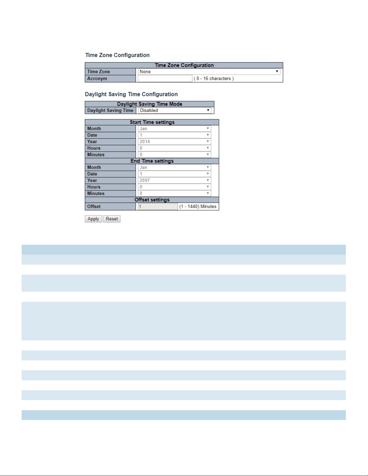
System Time
This page allows you to configure the Time Zone.
Object Description
Time Zone Configuration
Time Zone Lists various Time Zones worldwide. Select appropriate Time Zone from the drop down
Acronym User can set the acronym of the time zone. This is a User configurable acronym to identify the time zone. (
Range : Up to 16 characters )
Daylight Saving Time Configuration
Daylight
Saving
Time
Recurring Configurations
Start time settings
Week Select the starting week number.
Day Select the starting day.
Month Select the starting month.
Hours Select the starting hour.
Minutes Select the starting minute
End time settings
Week Select the ending week number.
This is used to set the clock forward or backward according to the configurations set below for a defined
Daylight Saving Time duration. Select ‘Disable’ to disable the Daylight Saving Time configuration. Select
‘Recurring’ and configure the Daylight Saving Time duration to repeat the configuration every year. Select
‘Non-Recurring’ and configure the Daylight Saving Time duration for single time configuration. ( Default :
Disabled )
TECH SUPPORT: 1.888.678.9427
INS_CNGE24FX12TX12MS[POE] Rev. 2.22.18 PAGE 20
Page 21

INSTRUCTION MANUAL CNGE24FX12TX12MS[POE]
Object Description
Day Select the ending day.
Month Select the ending month.
Hours Select the ending hour.
Minutes Select the ending minute
Offset settings
Offset Enter the number of minutes to add during Daylight Saving Time. ( Range: 1 to 1440 )
Non Recurring Configurations
Start time settings
Month Select the starting month.
Date Select the starting date.
Year Select the starting year.
Hours Select the starting hour.
Minutes Select the starting minute
End time settings
Month Select the ending month.
Date Select the ending date.
Year Select the ending year.
Hours Select the ending hour.
Minutes Select the ending minute
Offset settings
Offset Enter the number of minutes to add during Daylight Saving Time. ( Range: 1 to 1440 )
TECH SUPPORT: 1.888.678.9427
INS_CNGE24FX12TX12MS[POE] Rev. 2.22.18 PAGE 21
Page 22

INSTRUCTION MANUAL CNGE24FX12TX12MS[POE]
System Log
Configure System Log on this page.
Object Description
Server Mode Indicates the server mode operation. When the mode operation is enabled, the syslog message
will send out to syslog server. The syslog protocol is based on UDP communication and received
on UDP port 514 and the syslog server will not send acknowledgments back sender since UDP is a
connectionless protocol and it does not provide acknowledgments. The syslog packet will always
send out even if the syslog server does not exist. Possible modes are:
Enabled: Enable server mode operation.
Disabled: Disable server mode operation.
Server Address Indicates the IPv4 host address of syslog server. If the switch provide DNS feature, it also can be a
host name.
Syslog Level Indicates what kind of messages will sent to the syslog server. Possible modes are:
Error: Send the specific messages which severity code is less or equal than Error(3).
Warning: Send the specific messages which severity code is less or equal than Warning(4).
Notice: Send the specific messages which severity code is less or equal than Notice(5).
Informational: Send the specific messages which severity code is less or equal than
Informational(6).
Apply Click to apply changes.
Revert Click to revert to previous values.
TECH SUPPORT: 1.888.678.9427
INS_CNGE24FX12TX12MS[POE] Rev. 2.22.18 PAGE 22
Page 23
INSTRUCTION MANUAL CNGE24FX12TX12MS[POE]
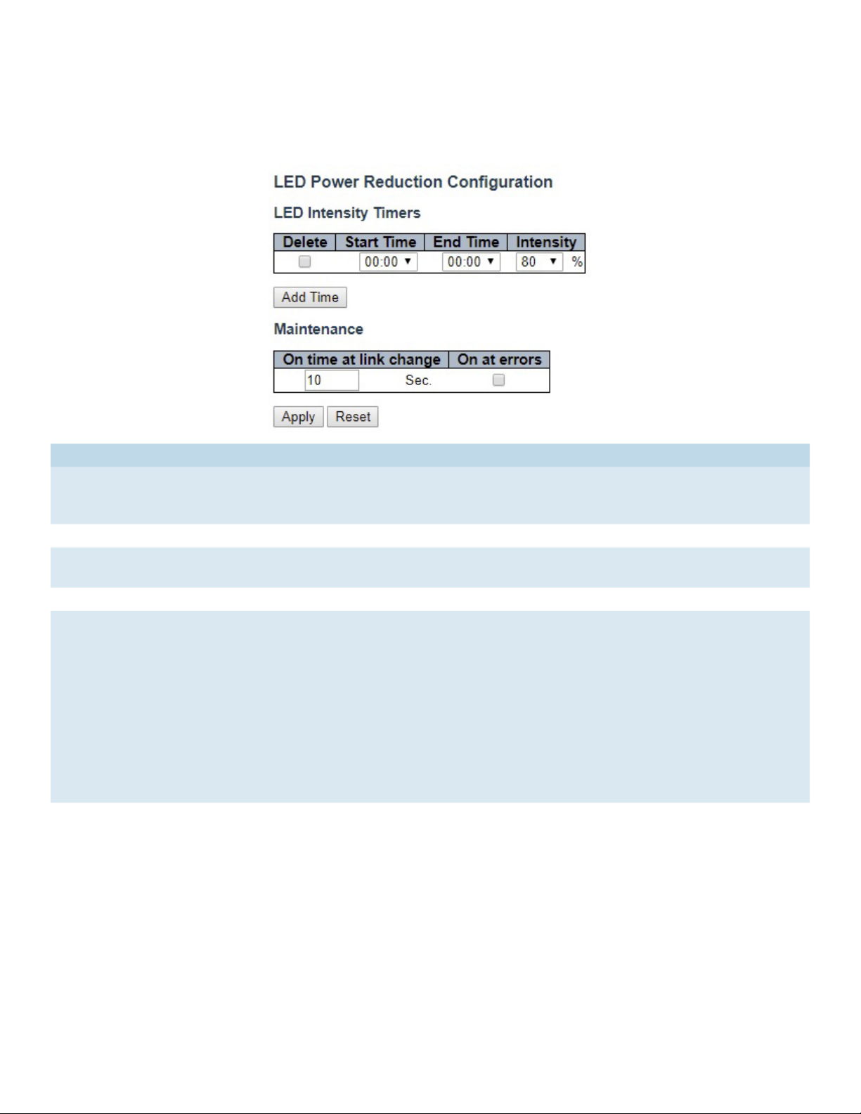
Green Ethernet
LED
Object Description
LEDs Intensity The LEDs power consumption can be reduced by lowering the LEDs intensity. LEDs intensity could
for example be lowered during night time, or they could be turn completely off. It is possible to
configure 24 different hours of the day, at where the LEDs intensity should be set.
Start Time The time at which the LEDs intensity shall be set to the corresponding intensity.
End Time The time at which the LEDs intensity shall be set to a new intensity. If no intensity is specified for
the next hour, the intensity is set to default intensity.
Intensity The LEDs intensity (100% = Full power, 0% = LED off).
Maintenance On time at link change
When a network administrator does maintenance of the switch (e.g. adding or moving users) he
might want to have full LED intensity during the maintenance period . Therefore it is possible to
specify that the LEDs shall use full intensity a specific period of time. Maintenance Time is the
number of seconds that the LEDs will have full intensity after either a port has changed link state,
or the LED pushbutton has been pushed. Valid range is from 0 to 65535 seconds.
On at errors
In the case where maximum power saving is enabled by turning the LEDs completely off, it might
be convenient to indicate to the network administrator that an error has been recorded in the
system log. By checking the "On at errors" the LEDs will be turned on at 100% in the case that
errors are logged in the system log.
TECH SUPPORT: 1.888.678.9427
INS_CNGE24FX12TX12MS[POE] Rev. 2.22.18 PAGE 23
Page 24
INSTRUCTION MANUAL CNGE24FX12TX12MS[POE]
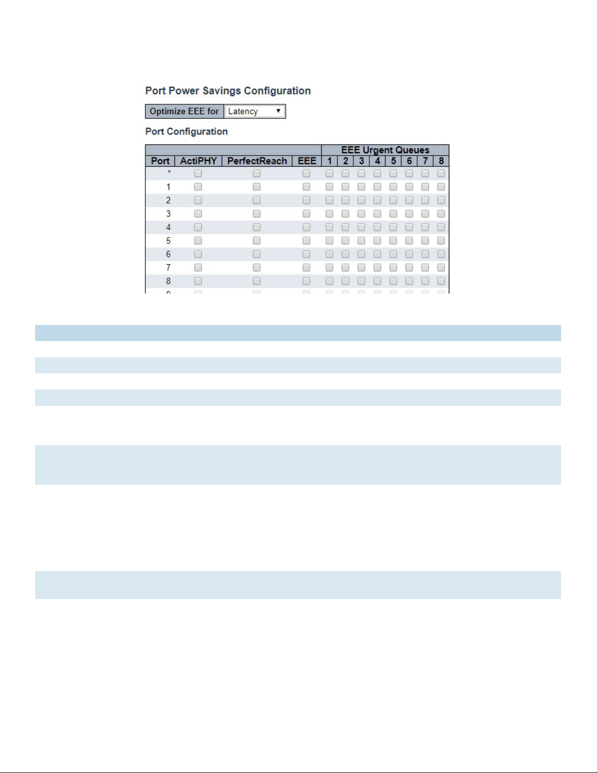
Port Power Savings
This page allows the user to configure the port power saving features.
Object Description
Port Power Savings Configuration
Optimize EEE for The switch can be set to optimize EEE for either best power saving or least traffic latency.
Port Configuration
Port The switch port number of the logical port.
ActiPHY Link down power savings enabled.
ActiPHY works by lowering the power for a port when there is no link. The port is power up for
short moment in order to determine if cable is inserted.
PerfectReach Cable length power savings enabled.
PerfectReach works by determining the cable length and lowering the power for ports with
short cables.
EEE Controls whether EEE is enabled for this switch port. For maximizing power savings, the circuit
isn’t started at once transmit data is ready for a port, but is instead queued until a burst of data
is ready to be transmitted. This will give some traffic latency.
If desired it is possible to minimize the latency for specific frames, by mapping the frames to a
specific queue (done with QOS), and then mark the queue as an urgent queue. When an urgent
queue gets data to be transmitted, the circuits will be powered up at once and the latency will
be reduced to the wakeup time.
EEE Urgent Queues Queues set will activate transmission of frames as soon as data is available.
Otherwise the queue will postpone transmission until a burst of frames can be transmitted.
TECH SUPPORT: 1.888.678.9427
INS_CNGE24FX12TX12MS[POE] Rev. 2.22.18 PAGE 24
Page 25
INSTRUCTION MANUAL CNGE24FX12TX12MS[POE]
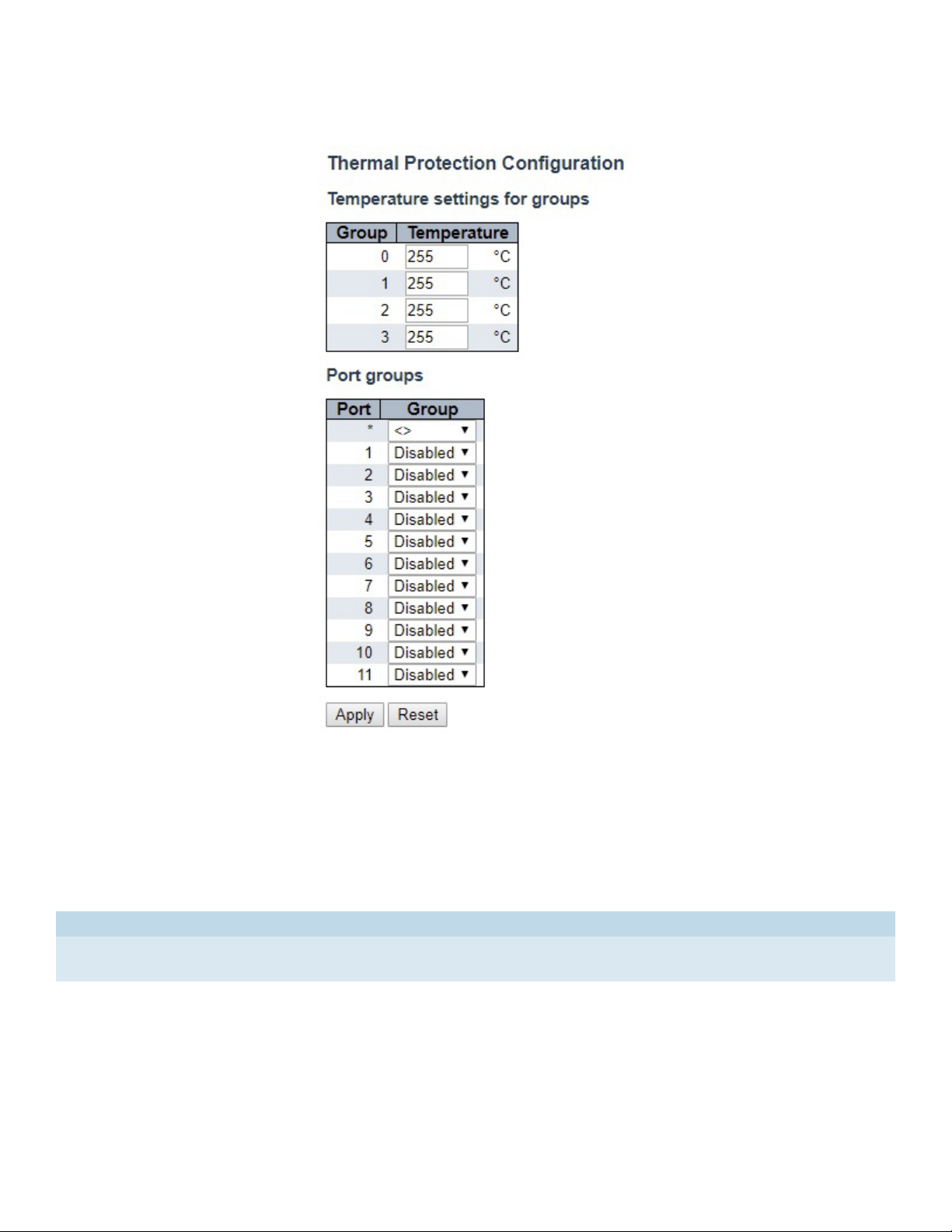
Thermal Protection
This page allows the user to inspect and configure the current setting for controlling thermal
protection. Thermal protection is used to protect the chip from getting overheated.
When the temperature exceeds the configured thermal protection temperature, ports will be
turned off in order to decrease the power consumption. It is possible to arrange the ports with
different groups. Each group can be given a temperature at which the corresponding ports shall
be turned off.
Object Description
Temperature The temperature at which the ports with the corresponding group will be turned off.
Temperatures between 0 and 255 C are supported.
Group The group the port belongs to. 4 groups are supported.
TECH SUPPORT: 1.888.678.9427
INS_CNGE24FX12TX12MS[POE] Rev. 2.22.18 PAGE 25
Page 26
INSTRUCTION MANUAL CNGE24FX12TX12MS[POE]
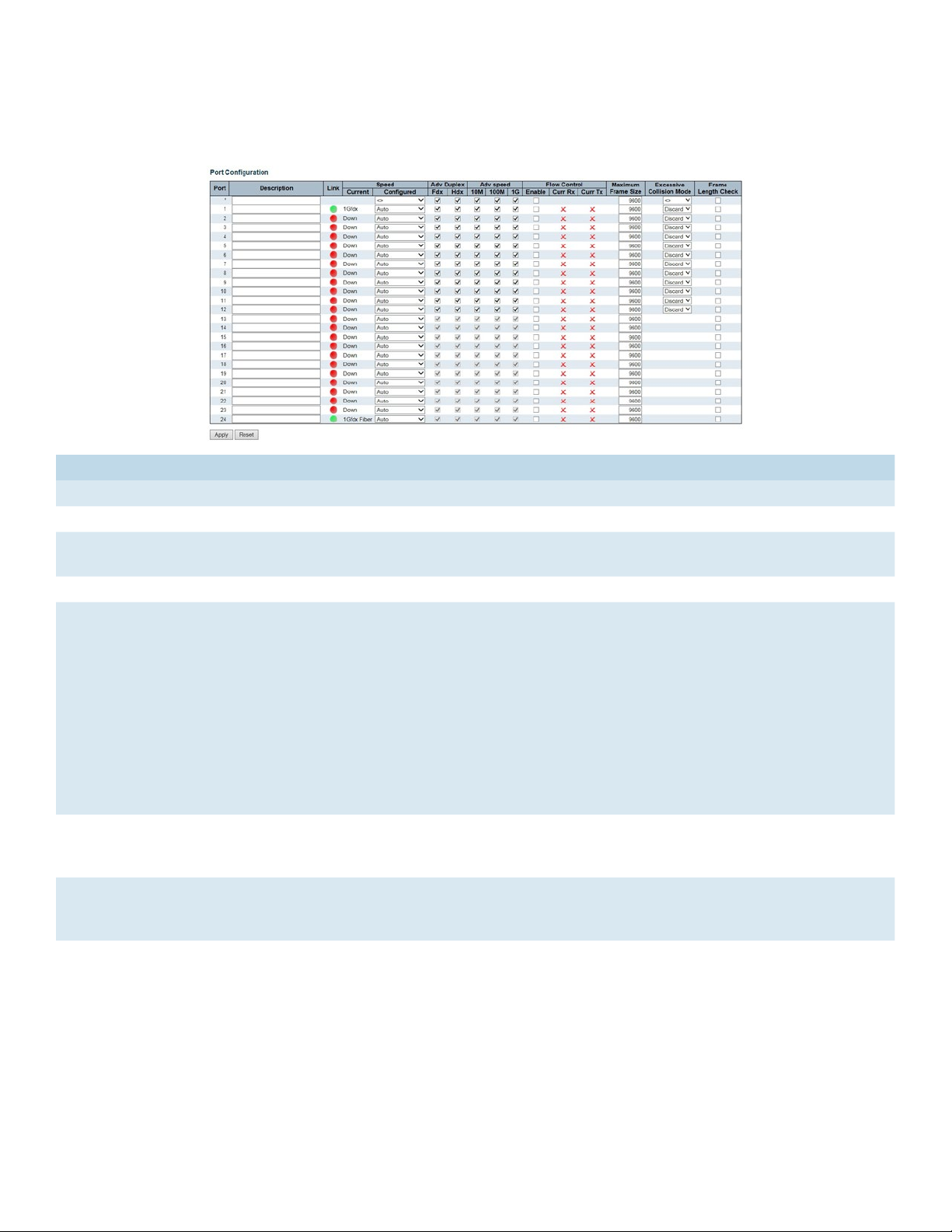
Ports
This page displays curent port configurations. Ports can also be configured here.
Object Description
Port This is the logical port number for this row.
Description The description of the port. It is an ASCII string no longer than 256 characters.
Link The current link state is displayed graphically. Green indicates the link is up and red that it is
down.
Current Link Speed Provides the current link speed of the port.
Configured Link
Speed
Advertise Duplex When duplex is set as auto i.e auto negotiation, the port will only advertise the specified
Advertise Speed When Speed is set as auto i.e auto negotiation, the port will only advertise the specified
Flow Control When Auto Speed is selected on a port, this section indicates the flow control capability that
Selects any available link speed for the given switch port. Only speeds supported by the
specific ports are shown. Possible speeds are:
Disabled - Disables the switch port operation.
Auto - Port auto negotiating speed with the link partner and selects the highest speed that is
compatible with the link partner.
10Mbps HDX - Forces the cu port in 10Mbps half duplex mode.
10Mbps FDX - Forces the cu port in 10Mbps full duplex mode.
100Mbps HDX - Forces the cu port in 100Mbps half duplex mode.
100Mbps FDX - Forces the cu port in 100Mbps full duplex mode.
1Gbps FDX - Forces the port in 1Gbps full duplex.
2.5Gbps FDX - Forces the port in 2.5Gbps full duplex mode.
duplex as either Fdx or Hdx to the link partner. By default port will advertise all the supported
duplexes if the Duplex is Auto.
speeds (10M 100M 1G) to the link partner. By default port will advertise all the supported
speeds if speed is set as Auto.
is advertised to the link partner.
When a fixed-speed setting is selected, that is what is used. The Current Rx column indicates
whether pause frames on the port are obeyed, and the Current Tx column indicates whether
pause frames on the port are transmitted. The Rx and Tx settings are determined by the result
of the last Auto-Negotiation.
Check the configured column to use flow control. This setting is related to the setting for
Configured Link Speed.
TECH SUPPORT: 1.888.678.9427
INS_CNGE24FX12TX12MS[POE] Rev. 2.22.18 PAGE 26
Page 27

INSTRUCTION MANUAL CNGE24FX12TX12MS[POE]
Object Description
Maximum Frame Size Enter the maximum frame size allowed for the switch port, including FCS.
Excessive Collision
Mode
Frame Check Length Configures whether frames with incorrect frame length in the EtherType/Length field shall
Apply Click to apply changes.
Reset Click to revert to previous values.
Configure port transmit collision behavior.
Discard: Discard frame after 16 collisions (default).
Restart: Restart back off algorithm after 16 collisions.
be dropped. An Ethernet frame contains a field EtherType which can be used to indicate the
frame payload size (in bytes) for values of 1535 and below. If the EtherType/Length field is
above 1535, it indicates that the field is used as an EtherType (indicating which protocol is
encapsulated in the payload of the frame). If "frame length check" is enabled, frames with
payload size less than 1536 bytes are dropped, if the EtherType/Length field doesn't match
the actually payload length. If "frame length check" is disabled, frames are not dropped due
to frame length mismatch.
Note: No drop counters count frames dropped due to frame length mismatch.
TECH SUPPORT: 1.888.678.9427
INS_CNGE24FX12TX12MS[POE] Rev. 2.22.18 PAGE 27
Page 28
INSTRUCTION MANUAL CNGE24FX12TX12MS[POE]
DHCP
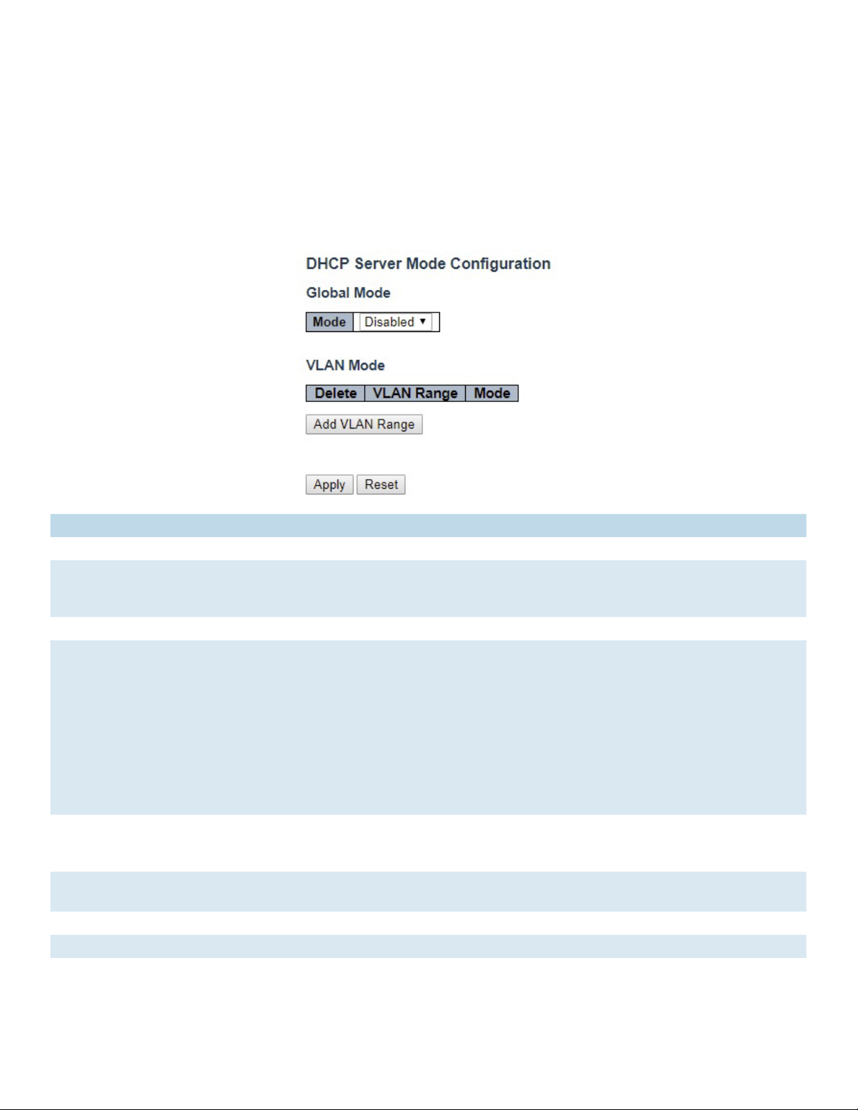
DHCP Server
Mode
This page configures global mode and VLAN mode to enable/disable DHCP server per system
and per VLAN.
Object Description
Global Mode
Mode Configure the operation mode per system. Possible modes are:
Enabled: Enable DHCP server per system.
Disabled: Disable DHCP server per system.
VLAN Mode
VLAN Range Indicate the VLAN range in which DHCP server is enabled or disabled. The first VLAN ID must be
smaller than or equal to the second VLAN ID. BUT, if the VLAN range contains only 1 VLAN ID, then
you can just input it into either one of the first and second VLAN ID or both.
On the other hand, if you want to disable existed VLAN range, then you can follow the steps.
1. press “Add VLAN Range” to add a new VLAN range.
2. input the VLAN range that you want to disable.
3. choose Mode to be Disabled.
4. press “Save” to apply the change.
Then, you will see the disabled VLAN range is removed from the DHCP Server mode configuration
page.
Mode Indicate the operation mode per VLAN. Possible modes are:
Enabled: Enable DHCP server per VLAN.
Disabled: Disable DHCP server pre VLAN.
Add VLAN
Range
Apply Click to apply changes.
Reset Click to undo any changes made locally and revert to previously saved values.
Click to apply to add a new VLAN range.
TECH SUPPORT: 1.888.678.9427
INS_CNGE24FX12TX12MS[POE] Rev. 2.22.18 PAGE 28
Page 29
INSTRUCTION MANUAL CNGE24FX12TX12MS[POE]
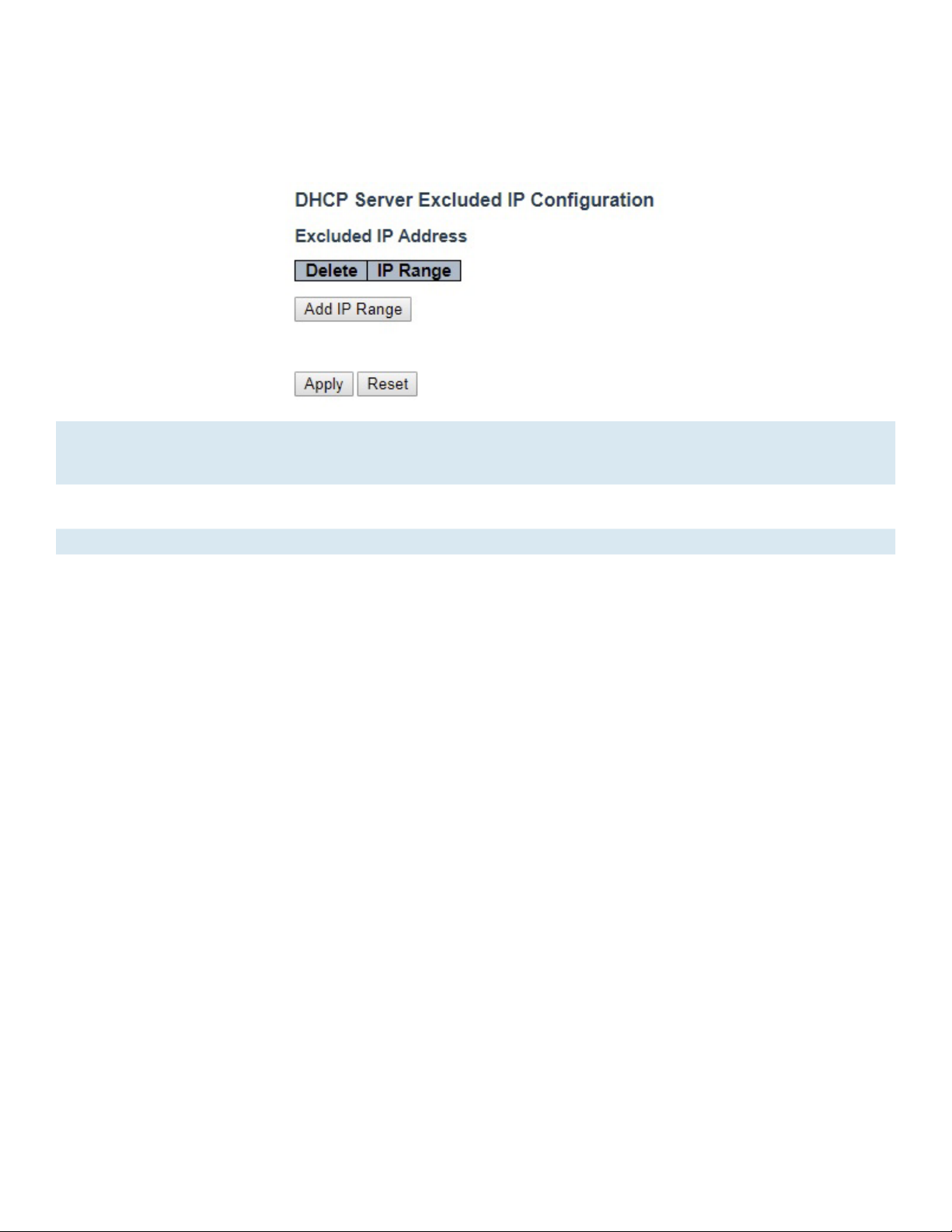
Excluded IP
This page configures excluded IP addresses. DHCP server will not allocate these excluded IP
addresses to DHCP client.
IP Range Define the IP range to be excluded IP addresses. The first excluded IP must be smaller than or equal
to the second excluded IP. BUT, if the IP range contains only 1 excluded IP, then you can just input it to
either one of the first and second excluded IP or both.
Add IP
Range
Apply Click to apple changes.
Reset Click to undo any changes made locally and revert to previously saved values.
Click to add a new IP range.
TECH SUPPORT: 1.888.678.9427
INS_CNGE24FX12TX12MS[POE] Rev. 2.22.18 PAGE 29
Page 30

INSTRUCTION MANUAL CNGE24FX12TX12MS[POE]
Pool
This page manages DHCP pools. According to the DHCP pool, DHCP server will allocate IP
address and deliver configuration parameters to DHCP client.
Object Description
Pool Setting Add or delete pools.
Adding a pool and giving a name is to create a new pool with “default” configuration. If you want to
configure all settings including type, IP subnet mask and lease time, you can click the pool name to
go into the configuration page.
Name Configure the pool name that accepts all printable characters, except white space. If you want to
configure the detail settings, you can click the pool name to go into the configuration page.
Type Display which type of the pool is.
Network: the pool defines a pool of IP addresses to service more than one DHCP client.
Host: the pool services for a specific DHCP client identified by client identifier or hardware address.
If “-” is displayed, it means not defined.
IP Display network number of the DHCP address pool.
If “-” is displayed, it means not defined.
Subnet Mask Display subnet mask of the DHCP address pool.
If “-” is displayed, it means not defined.
Lease Time Display lease time of the pool.
Add New Pool Click to add a new DHCP pool.
Apply Click to apply changes.
Reset Click to undo any changes made locally and revert to previously saved values.
TECH SUPPORT: 1.888.678.9427
INS_CNGE24FX12TX12MS[POE] Rev. 2.22.18 PAGE 30
Page 31

INSTRUCTION MANUAL CNGE24FX12TX12MS[POE]
DHCP Pool Configuration
DHCP Pool Configuration Help
DHCP Pool Configuration
This page configures all settings of a DHCP pool.
TECH SUPPORT: 1.888.678.9427
INS_CNGE24FX12TX12MS[POE] Rev. 2.22.18 PAGE 31
Page 32

INSTRUCTION MANUAL CNGE24FX12TX12MS[POE]
Object Description
Pool
Name Select a pool by pool name.
Setting
Name Display the selected pool name.
Type Specify which type of the pool is.
Network: the pool defines a pool of IP addresses to service more than one DHCP client.
Host: the pool services for a specific DHCP client identified by client identifier or hardware
address.
IP Specify network number of the DHCP address pool.
Subnet Mask DHCP option 1.
Specify subnet mask of the DHCP address pool.
Lease Time DHCP option 51, 58 and 59.
Specify lease time that allows the client to request a lease time for the IP address. If all are 0's,
then it means the lease time is infinite.
Domain Name DHCP option 15.
Specify domain name that client should use when resolving hostname via DNS.
Broadcast Address DHCP option 28.
Specify the broadcast address in use on the client's subnet.
Default Router DHCP option 3.
Specify a list of IP addresses for routers on the client's subnet.
DNS Server DHCP option 6.
Specify a list of Domain Name System name servers available to the client.
NTP Server DHCP option 42.
Specify a list of IP addresses indicating NTP servers available to the client.
NetBIOS Node Type DHCP option 46.
Specify NetBIOS node type option to allow Netbios over TCP/IP clients which are
configurable to be configured as described in RFC 1001/1002.
NetBIOS Scope DHCP option 47.
Specify the NetBIOS over TCP/IP scope parameter for the client as specified in RFC
1001/1002.
NetBIOS Name Server DHCP option 44.
Specify a list of NBNS name servers listed in order of preference.
NIS Domain Name DHCP option 40.
Specify the name of the client's NIS domain.
NIS Server DHCP option 41.
Specify a list of IP addresses indicating NIS servers available to the client.
Client Identifier DHCP option 61.
Specify client's unique identifier to be used when the pool is the type of host.
Hardware Address Specify client's hardware(MAC) address to be used when the pool is the type of host.
Client Name DHCP option 12.
Specify the name of client to be used when the pool is the type of host.
TECH SUPPORT: 1.888.678.9427
INS_CNGE24FX12TX12MS[POE] Rev. 2.22.18 PAGE 32
Page 33

INSTRUCTION MANUAL CNGE24FX12TX12MS[POE]
Object Description
Vendor i Class
Identifier
Vendor i Specific
Information
Apply Click to apply changes.
Reset Click to undo any changes made locally and revert to previously saved values.
DHCP option 60.
Specify to be used by DHCP client to optionally identify the vendor type and configuration of
a DHCP client. DHCP server will deliver the corresponding option 43 specific information to
the client that sends option 60 vendor class identifier.
DHCP option 43.
Specify vendor specific information according to option 60 vendor class identifier.
TECH SUPPORT: 1.888.678.9427
INS_CNGE24FX12TX12MS[POE] Rev. 2.22.18 PAGE 33
Page 34

INSTRUCTION MANUAL CNGE24FX12TX12MS[POE]
DHCP Snooping
Configure DHCP Snooping on this page.
Object Description
Snooping Mode Indicates the DHCP snooping mode operation. Possible modes are:
Enabled: Enable DHCP snooping mode operation. When DHCP snooping mode operation is
enabled, the DHCP requests messages will be forwarded to trusted ports and only allow reply
packets from trusted ports.
Disabled: Disable DHCP snooping mode operation.
Port Mode
Configuration
Apply Click to apply changes.
Reset Click to revert to previous values.
Indicates the DHCP snooping port mode. Possible port modes are:
Trusted: Configures the port as trusted source of the DHCP messages.
Untrusted: Configures the port as untrusted source of the DHCP messages.
TECH SUPPORT: 1.888.678.9427
INS_CNGE24FX12TX12MS[POE] Rev. 2.22.18 PAGE 34
Page 35

INSTRUCTION MANUAL CNGE24FX12TX12MS[POE]
DHCP Relay
A DHCP relay agent is used to forward and to transfer DHCP messages between the clients
and the server when they are not in the same subnet domain. It stores the incoming interface
IP address in the GIADDR field of the DHCP packet. The DHCP server can use the value of
GIADDR field to determine the assigned subnet. For such condition, please make sure the switch
configuration of VLAN interface IP address and PVID (Port VLAN ID) correctly.
Object Description
Relay Mode Indicates the DHCP relay mode operation. Possible modes are:
Enabled: Enable DHCP relay mode operation. When DHCP relay mode operation is enabled, the
agent forwards and transfers DHCP messages between the clients and the server when they are
not in the same subnet domain. And the DHCP broadcast message won’t be flooded for security
considerations.
Disabled: Disable DHCP relay mode operation.
Relay Server Indicates the DHCP relay server IP address.
Relay
Information
Mode
Relay
Information
Policy
Apply Click to apply changes.
Reset Click to revert to previous values.
Indicates the DHCP relay information mode option operation. The option 82 circuit ID format as
“[vlan_id][module_id][port_no]”. The first four characters represent the VLAN ID, the fifth and sixth
characters are the module ID (in standalone device it always equal 0, in stackable device it means
switch ID), and the last two characters are the port number. For example, “00030108” means the
DHCP message receives form VLAN ID 3, switch ID 1, port No 8. And the option 82 remote ID value
is equal the switch MAC address.
Possible modes are:
Enabled: Enable DHCP relay information mode operation. When DHCP relay information mode
operation is enabled, the agent inserts specific information (option 82) into a DHCP message when
forwarding to DHCP server and removes it from a DHCP message when transferring to DHCP client.
It only works when DHCP relay operation mode is enabled.
Disabled: Disable DHCP relay information mode operation.
Indicates the DHCP relay information option policy. When DHCP relay information mode operation
is enabled, if the agent receives a DHCP message that already contains relay agent information it will
enforce the policy. The ‘Replace’ policy is invalid when relay information mode is disabled. Possible
policies are:
Keep: Keep the original relay information when a DHCP message that already contains it is received.
TECH SUPPORT: 1.888.678.9427
INS_CNGE24FX12TX12MS[POE] Rev. 2.22.18 PAGE 35
Page 36

INSTRUCTION MANUAL CNGE24FX12TX12MS[POE]
Security
Switch Security
Users
This page provides an overview of the current users. Currently the only way to login as another
user on the web server is to close and reopen the browser.
Object Description
User Name A string identifying the user name that this entry should belong to. The allowed string length is 1
to 31. The valid user name allows letters, numbers and underscores.
Password The password of the user. The allowed string length is 0 to 31. Any printable characters including
space are accepted.
Privilege Level The privilege level of the user. The allowed range is 1 to 15. If the privilege level value is 15, it can
access all groups, i.e. that is granted the fully control of the device. But others value need to refer
to each group privilege level. User’s privilege should be same or greater than the group privilege
level to have the access of that group. By default setting, most group privilege level 5 has the
read-only access and privilege level 10 has the read-write access. And the system maintenance
(software upload, factory defaults and etc.) need user privilege level 15. Generally, the privilege
level 15 can be used for an administrator account, privilege level 10 for a standard user account
and privilege level 5 for a guest account.
Add New User Click to add a new user.
Cancel Click to undo any changes made locally and return to the Users.
Apply Click to apply changes.
Reset Click to undo any changes made locally and revert to previously saved values.
Delete User Click to delete the currently selected user.
TECH SUPPORT: 1.888.678.9427
INS_CNGE24FX12TX12MS[POE] Rev. 2.22.18 PAGE 36
Page 37

INSTRUCTION MANUAL CNGE24FX12TX12MS[POE]
Privilege Levels
This page provides an overview of the privilege levels.
Group Name The name identifying the privilege group. In most cases, a privilege level group consists of a
single module (e.g. LACP, RSTP or QoS), but a few of them contains more than one. The following
description defines these privilege level groups in details:
System: Contact, Name, Location, Timezone, Daylight Saving Time, Log.
Security: Authentication, System Access Management, Port (contains Dot1x port, MAC based and
the MAC Address Limit), ACL, HTTPS, SSH, ARP Inspection, IP source guard.
IP: Everything except ‘ping’.
Port: Everything except ‘VeriPHY’.
Diagnostics: ‘ping’ and ‘VeriPHY’.
Maintenance: CLI- System Reboot, System Restore Default, System Password, Configuration
Save, Configuration Load and Firmware Load. Web- Users, Privilege Levels and everything in
Maintenance.
Debug: Only present in CLI.
Privilege Levels Every group has an authorization Privilege level for the following sub groups:
configuration read-only, configuration/execute read-write, status/statistics read-only, status/
statistics read-write (e.g. for clearing of statistics). User Privilege should be same or greater than the
authorization Privilege level to have the access to that group.
Apply Click to apply changes.
Reset Click to revert to previous values.
TECH SUPPORT: 1.888.678.9427
INS_CNGE24FX12TX12MS[POE] Rev. 2.22.18 PAGE 37
Page 38

INSTRUCTION MANUAL CNGE24FX12TX12MS[POE]
Authentication Method
This page allows you to configure how a user is authenticated when he logs into the switch via one
of the management client interfaces.
Object Description
Client The management client for which the configuration below applies.
Methods Method can be set to one of the following values:
• no: Authentication is disabled and login is not possible.
• local: Use the local user database on the switch for authentication.
• radius: Use remote RADIUS server(s) for authentication.
• tacacs+: Use remote TACACS+ server(s) for authentication.
Methods that involve remote servers are timed out if the remote servers are offline. In this case the
next method is tried. Each method is tried from left to right and continues until a method either
approves or rejects a user. If a remote server is used for primary authentication it is recommended
to configure secondary authentication as ‘local’. This will enable the management client to login via
the local user database if none of the configured authentication servers are alive.
Apply Click to apply changes.
Reset Click to revert to previous values.
TECH SUPPORT: 1.888.678.9427
INS_CNGE24FX12TX12MS[POE] Rev. 2.22.18 PAGE 38
Page 39

INSTRUCTION MANUAL CNGE24FX12TX12MS[POE]
SSH
Configure SSH on this page.
Object Description
Mode Indicates the SSH mode operation. Possible modes are: Enabled: Enable SSH mode operation.
Disabled: Disable SSH mode operation.
Apply Click to apply changes.
Reset Click to revert to previous values.
TECH SUPPORT: 1.888.678.9427
INS_CNGE24FX12TX12MS[POE] Rev. 2.22.18 PAGE 39
Page 40

INSTRUCTION MANUAL CNGE24FX12TX12MS[POE]
HTTPS
Configure HTTPS on this page.
Object Description
Mode Indicates the HTTPS mode operation. When the current connection is HTTPS, to apply HTTPS
disabled mode operation will automatically redirect web browser to an HTTP connection. Possible
modes are: Enabled: Enable HTTPS mode operation. Disabled: Disable HTTPS mode operation.
Automatic
Redirect
Certificate
Maintain
Certificate
Algorithm
PassPhrase The pattern is used for encrypting the certification.
Certificate
Upload
Certificate
Status
Apply Click to apply changes.
Reset Click to revert to previous values.
Indicates the HTTPS redirect mode operation. It only significant if HTTPS mode “Enabled” is
selected. Automatically redirects web browser to an HTTPS connection when both HTTPS mode
and Automatic Redirect are enabled. Possible modes are:
Enabled: Enable HTTPS redirect mode operation.
Disabled: Disable HTTPS redirect mode operation.
This field only can be configured when HTTPS is disabled. It is used to maintain the certification.
Possible actions are:
None: None action for certification.
Delete: To delete certification.
Upload: To upload certification, there are two kind of upload method can be selected: Web Browser
or URL.
Generate: To generate certification.
HTTPS can generate two types of certification. Possible types are:
RSA: RSA certification.
DSA: DSA certification.
Possible modes are:
Web Browser: To Upload certification via Web browser.
URL: To Upload certification via URL, the supported protocols are HTTP, HTTPS, TFTP and FTP.
The URL format is <protocol>://[<username>[:<password>]@]<host>[:<port>][/<path>]/<file_
name>. For example, tftp://10.10.10.10/new_image_path/new_image.dat, http://username:passwo
rd@10.10.10.10:80/new_image_path/new_image.dat. A valid file name is a text string drawn from
alphabet (A-Za-z), digits (0-9), dot (.), hyphen (-), under score(_). The maximum length is 63 and
hyphen must not be first character. The file name content that only contains '.' is not allowed.
Possible status is:
Switch secure HTTP certificate is presented: The certification is stored in HTTPS' database.
Switch secure HTTP certificate is not presented: No certification is stored in HTTPS' database.
Switch secure HTTP certificate is generating ...: The certification is generating.
TECH SUPPORT: 1.888.678.9427
INS_CNGE24FX12TX12MS[POE] Rev. 2.22.18 PAGE 40
Page 41

INSTRUCTION MANUAL CNGE24FX12TX12MS[POE]
Access Management
Configure access management table on this page. The maximum number of entries is 16. If the
application’s type matches any one of the access management entries, it will allow access to the
switch.
Object Description
Mode Indicates the access management mode operation. Possible modes are: Enabled: Enable access
management mode operation.
Disabled: Disable access management mode operation.
Delete Check to delete the entry. It will be deleted during the next save.
VLAN ID Indicates the VLAN ID for the access management entry.
Start IP address Indicates the start IP address for the access management entry.
End IP address Indicates the end IP address for the access management entry.
HTTP/HTTPS Indicates that the host can access the switch from HTTP/HTTPS interface if the host IP address
matches the IP address range provided in the entry.
SNMP Indicates that the host can access the switch from SNMP interface if the host IP address matches
the IP address range provided in the entry.
TELNET/SSH Indicates that the host can access the switch from TELNET/SSH interface if the host IP address
matches the IP address range provided in the entry.
Apply Click to apply changes.
Reset Click to revert to previous values.
Add New Entry Click to add a new access management entry.
TECH SUPPORT: 1.888.678.9427
INS_CNGE24FX12TX12MS[POE] Rev. 2.22.18 PAGE 41
Page 42

INSTRUCTION MANUAL CNGE24FX12TX12MS[POE]
SNMP
System
Configure SNMP on this page.
Object Description
Mode Indicates the SNMP mode operation. Possible modes are: Enabled: Enable SNMP mode
operation. Disabled: Disable SNMP mode operation.
Version Indicates the SNMP supported version. Possible versions are: SNMP v1: Set SNMP supported
version 1. SNMP v2c: Set SNMP supported version 2c. SNMP v3: Set SNMP supported version 3.
Read Community Indicates the community read access string to permit access to SNMP agent. The allowed
string length is 0 to 255, and the allowed content is the ASCII characters from 33 to 126.The
field is applicable only when SNMP version is SNMPv1 or SNMPv2c. If SNMP version is SNMPv3,
the community string will be associated with SNMPv3 communities table. It provides more
flexibility to configure security name than a SNMPv1 or SNMPv2c community string. In addition
to community string, a particular range of source addresses can be used to restrict source
subnet.
Write Community Indicates the community writes access string to permit access to SNMP agent. The allowed
string length is 0 to 255, and the allowed content is the ASCII characters from 33 to 126.
The field is applicable only when SNMP version is SNMPv1 or SNMPv2c. If SNMP version is
SNMPv3, the community string will be associated with SNMPv3 communities table. It provides
more flexibility to configure security name than a SNMPv1 or SNMPv2c community string. In
addition to community string, a particular range of source addresses can be used to restrict
source subnet.
Engine ID Indicates the SNMPv3 engine ID. The string must contain an even number (in hexadecimal
format) with number of digits between 10 and 64, but all-zeros and all-’F’s are not allowed.
Change of the Engine ID will clear all original local users.
Apply Click to apply changes.
Reset Click to revert to previous values.
TECH SUPPORT: 1.888.678.9427
INS_CNGE24FX12TX12MS[POE] Rev. 2.22.18 PAGE 42
Page 43

INSTRUCTION MANUAL CNGE24FX12TX12MS[POE]
SNMP Trap
Configure SNMP trap on this page.
Object Description
Global Settings
Mode Indicates the trap mode operation. Possible modes are: Enabled: Enable SNMP trap mode
operation. Disabled: Disable SNMP trap mode operation.
Trap Destination Configurations
Name Indicates the trap Configuration’s name. Indicates the trap destination’s name.
Enable Indicates the trap destination mode operation. Possible modes are: Enabled: Enable SNMP trap
mode operation. Disabled: Disable SNMP trap mode operation.
Version Indicates the SNMP trap supported version. Possible versions are: SNMPv1: Set SNMP trap
supported version 1. SNMPv2c: Set SNMP trap supported version 2c. SNMPv3: Set SNMP trap
supported version 3.
Destination
Address
Destination port Indicates the SNMP trap destination port. SNMP Agent will send SNMP message via this port,
Indicates the SNMP trap destination address. It allows a valid IP address in dotted decimal
notation (‘x.y.z.w’).
And it also allows a valid hostname. A valid hostname is a string drawn from the alphabet
(A-Za-z), digits (0-9), dot (.), dash (-). Spaces are not allowed, the first character must be an alpha
character, and the first and last characters must not be a dot or a dash.
Indicates the SNMP trap destination IPv6 address. IPv6 address is in 128-bit records represented
as eight fields of up to four hexadecimal digits with a colon separating each field (:). For
example, ‘fe80::215:c5ff:fe03:4dc7’. The symbol ‘::’ is a special syntax that can be used as a
shorthand way of representing multiple 16-bit groups of contiguous zeros; but it can appear only
once. It can also represent a legally valid IPv4 address. For example, ‘::192.168.10.1’.
the port range is 1~65535.
TECH SUPPORT: 1.888.678.9427
INS_CNGE24FX12TX12MS[POE] Rev. 2.22.18 PAGE 43
Page 44

INSTRUCTION MANUAL CNGE24FX12TX12MS[POE]
Click on “Add New Entry”.
The SNMP Trap Configuration page includes the following fields:
Object Description
Trap Mode Indicates the SNMP trap mode operation. Possible modes are: Enabled: Enable SNMP trap mode
operation. Disabled: Disable SNMP trap mode operation.
Trap Version Indicates the SNMP trap supported version. Possible versions are: SNMP v1: Set SNMP trap
supported version 1. SNMP v2c: Set SNMP trap supported version 2c. SNMP v3: Set SNMP trap
supported version 3.
Trap Community Indicates the community access string when sending SNMP trap packet. The allowed string length
is 0 to 255, and the allowed content is ASCII characters from 33 to 126.
Trap Destination
Address
Trap Link-up and
Link-down
Trap Destination
Port
Trap Inform
Timeout
(seconds)
TECH SUPPORT: 1.888.678.9427
Indicates the SNMP trap destination address. It allows a valid IP address in dotted decimal notation
(‘x.y.z.w ’).
And it also allows a valid hostname. A valid hostname is a string drawn from the alphabet (A-Za-z),
digits (0-9), dot (.), dash (-). Spaces are not allowed, the first character must be an alpha character,
and the first and last characters must not be a dot or a dash
Indicates the SNMP trap link-up and link-down mode operation. Possible modes are: Enabled:
Enable SNMP trap link-up and link-down mode operation. Disabled: Disable SNMP trap link-up and
link-down mode operation.
Indicates the SNMP trap destination port. SNMP Agent will send SNMP message via this port, the
port range is 1~65535.
Indicates the SNMP trap inform timeout. The allowed range is 0 to 2147.
INS_CNGE24FX12TX12MS[POE] Rev. 2.22.18 PAGE 44
Page 45

INSTRUCTION MANUAL CNGE24FX12TX12MS[POE]
Object Description
Trap Inform
Retry Times
Trap Probe
Security Engine
ID
Trap Security
Engine ID
Trap Security
Name
SNMP Trap
Event
Indicates the SNMP trap informs retry times. The allowed range is 0 to 255.
Indicates the SNMP trap probe security engine ID mode of operation. Possible values are:
Enabled: Enable SNMP trap probe security engine ID mode of operation.
Disabled: Disable SNMP trap probe security engine ID mode of operation.
Indicates the SNMP trap security engine ID. SNMPv3 sends traps and informs using USM for
authentication and privacy. A unique engine ID for these traps and informs is needed. When
“Trap Probe Security Engine ID” is enabled, the ID will be probed automatically. Otherwise, the ID
specified in this field is used. The string must contain an even number (in hexadecimal format) with
number of digits between 10 and 64, but all-zeros and all-’F’s are not allowed.
Indicates the SNMP trap security name. SNMPv3 traps and informs using USM for authentication
and privacy. A unique security name is needed when traps and informs are enabled.
System
Enable/disable that the Interface group's traps. Possible traps are:
Warm Start: Enable/disable Warm Start trap.
Cold Start: Enable/disable Cold Start trap.
Interface
Indicates that the Interface group's traps. Possible traps are: Indicates that the SNMP entity is
permitted to generate authentication failure traps. Possible modes are:
Link Up: Enable/disable Link up trap.
Link Down: Enable/disable Link down trap.
LLDP: Enable/disable LLDP trap.
Authentication
Indicates that the authentication group's traps. Possible traps are:
SNMP Authentication Fail : Enable/disable SNMP trap authentication failure trap.
Switch
Indicates that the Switch group's traps. Possible traps are:
STP: Enable/disable STP trap.
RMON: Enable/disable RMON trap.
Power Supply
Indicates that one of the power supply inputs has failed. Possible traps are:
PSFAIL: Enable/disable power supply fail trap.
Apply Click to apply changes.
Reset Click to revert to previous values.
TECH SUPPORT: 1.888.678.9427
INS_CNGE24FX12TX12MS[POE] Rev. 2.22.18 PAGE 45
Page 46

INSTRUCTION MANUAL CNGE24FX12TX12MS[POE]
SNMP Communities
Configure SNMPv3 community table on this page. The entry index key is Community.
Object Description
Delete Check to delete the entry. It will be deleted during the next save.
Community Indicates the community access string to permit access to SNMPv3 agent. The allowed string
length is 1 to 32, and the allowed content is ASCII characters from 33 to 126. The community
string will be treated as security name and map a SNMPv1 or SNMPv2c community string.
Source IP Indicates the SNMP access source address. A particular range of source addresses can be used
to restrict source subnet when combined with source mask.
Source Mask Indicates the SNMP access source address mask.
Apply Click to apply changes.
Reset Click to revert to previous values.
Add New Entry Click to add a new community.
TECH SUPPORT: 1.888.678.9427
INS_CNGE24FX12TX12MS[POE] Rev. 2.22.18 PAGE 46
Page 47

INSTRUCTION MANUAL CNGE24FX12TX12MS[POE]
SNMP Users
Configure SNMPv3 user table on this page. The entry index keys are Engine ID and User Name.
Object Description
Delete Check to delete the entry. It will be deleted during the next save.
Engine ID An octet string identifying the engine ID that this entry should belong to. The string must contain
an even number (in hexadecimal format) with number of digits between 10 and 64, but all-zeros
and all-’F’s are not allowed. The SNMPv3 architecture uses the User-based Security Model (USM)
for message security and the View-based Access Control Model (VACM) for access control. For
the USM entry, the usmUserEngineID and usmUserName are the entry’s keys. In a simple agent,
usmUserEngineID is always that agent’s own snmpEngineID value. The value can also take the value
of the snmpEngineID of a remote SNMP engine with which this user can communicate. In other
words, if user engine ID equal system engine ID then it is local user; otherwise it’s remote user.
User name A string identifying the user name that this entry should belong to. The allowed string length is 1 to
32, and the allowed content is ASCII characters from 33 to 126.
Security Level Indicates the security model that this entry should belong to. Possible security models are:
NoAuth, NoPriv: No authentication and no privacy.
Auth, NoPriv: Authentication and no privacy.
Auth, Priv: Authentication and privacy.
The value of security level cannot be modified if entry already exists. That means it must first be
ensured that the value is set correctly.
Authentication
Protocol
Authentication
Password
Privacy Protocol Indicates the privacy protocol that this entry should belong to. Possible privacy protocols are:
Privacy PasswordA string identifying the privacy password phrase. The allowed string length is 8 to 32, and the
Apply Click to apply changes.
Reset Click to revert to previous values.
Add New Entry Click to add new user configurations.
Indicates the authentication protocol that this entry should belong to. Possible authentication
protocols are:
None: No authentication protocol.
MD5: An optional flag to indicate that this user uses MD5 authentication protocol.
SHA: An optional flag to indicate that this user uses SHA authentication protocol.
The value of security level cannot be modified if entry already exists. That means must first ensure
that the value is set correctly.
A string identifying the authentication password phrase. For MD5 authentication protocol, the
allowed string length is 8 to 32. For SHA authentication protocol, the allowed string length is 8 to
40. The allowed content is ASCII characters from 33 to 126.
None: No privacy protocol.
DES: An optional flag to indicate that this user uses DES authentication protocol.
AES: An optional flag to indicate that this user uses AES authentication protocol.
allowed content is ASCII characters from 33 to 126.
TECH SUPPORT: 1.888.678.9427
INS_CNGE24FX12TX12MS[POE] Rev. 2.22.18 PAGE 47
Page 48

INSTRUCTION MANUAL CNGE24FX12TX12MS[POE]
SNMP Groups
Configure SNMPv3 group table on this page. The entry index keys are Security Model and
Security Name.
Object Description
Delete Check to delete the entry. It will be deleted during the next save.
Security Model Indicates the security model that this entry should belong to. Possible security models are:
v1: Reserved for SNMPv1.
v2c: Reserved for SNMPv2c.
usm: User-based Security Model (USM).
Security Name A string identifying the security name that this entry should belong to. The allowed string
length is 1 to 32, and the allowed content is ASCII characters from 33 to 126.
Group Name A string identifying the group name that this entry should belong to. The allowed string length
is 1 to 32, and the allowed content is ASCII characters from 33 to 126.
Apply Click to apply changes.
Reset Click to revert to previous values.
Add New Entry Click to add a new group.
TECH SUPPORT: 1.888.678.9427
INS_CNGE24FX12TX12MS[POE] Rev. 2.22.18 PAGE 48
Page 49

INSTRUCTION MANUAL CNGE24FX12TX12MS[POE]
SNMP Views
Configure SNMPv3 view table on this page. The entry index keys are View Name and OID Subtree.
Object Description
Delete Check to delete the entry. It will be deleted during the next save.
View Name A string identifying the view name that this entry should belong to. The allowed string length is 1
to 32, and the allowed content is ASCII characters from 33 to 126.
View Type Indicates the view type that this entry should belong to. Possible view types are: included: An
optional flag to indicate that this view subtree should be included. excluded: An optional flag
to indicate that this view subtree should be excluded. In general, if a view entry’s view type is
‘excluded’, there should be another view entry existing with view type as ‘included’ and its OID
subtree should overstep the ‘excluded’ view entry.
OID Subtree The OID defining the root of the subtree to add to the named view. The allowed OID length is 1
to 128. The allowed string content is digital number or asterisk(*).
Apply Click to apply changes.
Reset Click to revert to previous values.
Add New Entry Click to add new viewer configurations.
TECH SUPPORT: 1.888.678.9427
INS_CNGE24FX12TX12MS[POE] Rev. 2.22.18 PAGE 49
Page 50

INSTRUCTION MANUAL CNGE24FX12TX12MS[POE]
SNMP Access
Configure SNMPv3 access table on this page. The entry index keys are Group Name, Security
Model and Security Level.
Object Description
Delete Check to delete the entry. It will be deleted during the next save.
Group Name A string identifying the group name that this entry should belong to. The allowed string length
is 1 to 32, and the allowed content is ASCII characters from 33 to 126.
Security Model Indicates the security model that this entry should belong to. Possible security models are:
any: Any security model accepted (v1|v2c|usm).
v1: Reserved for SNMPv1.
v2c: Reserved for SNMPv2c.
usm: User-based Security Model (USM).
Security Level Indicates the security model that this entry should belong to. Possible security models are:
NoAuth, NoPriv: No authentication and no privacy.
Auth, NoPriv: Authentication and no privacy.
Auth, Priv: Authentication and privacy.
Read View Name The name of the MIB view defining the MIB objects for which this request may request the
current values. The allowed string length is 1 to 32, and the allowed content is ASCII characters
from 33 to 126.
Write View Name The name of the MIB view defining the MIB objects for which this request may potentially set
new values. The allowed string length is 1 to 32, and the allowed content is ASCII characters
from 33 to 126.
Apply Click to apply changes.
Reset Click to revert to previous values.
Add New Entry Click to add new access configurations.
TECH SUPPORT: 1.888.678.9427
INS_CNGE24FX12TX12MS[POE] Rev. 2.22.18 PAGE 50
Page 51

INSTRUCTION MANUAL CNGE24FX12TX12MS[POE]
RMON
Statistics
Configure RMON Statistics table on this page. The entry index key is ID.
Object Description
Delete Check to delete the entry. It will be deleted during the next save.
ID Indicates the index of the entry. The range is from 1 to 65535.
Data Source Indicates the port ID which wants to be monitored.
Apply Click to apply changes.
Reset Click to revert to previous values.
Add New Entry Click to add new RMON statistic configurations.
History
Configure RMON History table on this page. The entry index key is ID.
Object Description
Delete Check to delete the entry. It will be deleted during the next save.
ID Indicates the index of the entry. The range is from 1 to 65535.
Data Source Indicates the port ID which wants to be monitored.
Interval Indicates the interval in seconds for sampling the history statistics data. The range is from 1 to
3600, default value is 1800 seconds.
Buckets Indicates the maximum data entries associated this History control entry stored in RMON. The
range is from 1 to 3600, default value is 50.
Buckets Granted The number of data shall be saved in the RMON.
Apply Click to apply changes.
Reset Click to revert to previous values.
Add New Entry Click to add a new history configurations.
TECH SUPPORT: 1.888.678.9427
INS_CNGE24FX12TX12MS[POE] Rev. 2.22.18 PAGE 51
Page 52

INSTRUCTION MANUAL CNGE24FX12TX12MS[POE]
Alarm
Configure RMON Alarm table on this page. The entry index key is ID.
Object Description
Delete Check to delete the entry. It will be deleted during the next save.
ID Indicates the index of the entry. The range is from 1 to 65
Interval Indicates the interval in seconds for sampling and comparing the rising and falling threshold. The
range is from 1 to 2^31-1.
Variable Indicates the particular variable to be sampled, the possible variables are:
InOctets: The total number of octets received on the interface, including framing characters.
InUcastPkts: The number of uni-cast packets delivered to a higher-layer protocol. InNUcastPkts:
The number of broad-cast and multi-cast packets delivered to a higher-layer protocol.
InDiscards: The number of inbound packets that are discarded even the packets are normal.
InErrors: The number of inbound packets that contained errors preventing them from being
deliverable to a higher-layer protocol.
InUnknownProtos: the number of the inbound packets that were discarded because of the
unknown or un-support protocol.
OutOctets: The number of octets transmitted out of the interface , including framing characters.
OutUcastPkts: The number of uni-cast packets that request to transmit.
OutNUcastPkts: The number of broad-cast and multi-cast packets that request to transmit.
OutDiscards: The number of outbound packets that are discarded event the packets are normal.
OutErrors: The number of outbound packets that could not be transmitted because of errors.
OutQLen: The length of the output packet queue (in packets).
Sample Type The method of sampling the selected variable and calculating the value to be compared against
the thresholds, possible sample types are: Absolute: Get the sample directly.
Delta: Calculate the difference between samples (default).
Value The value of the statistic during the last sampling period.
Startup Alarm The method of sampling the selected variable and calculating the value to be compared against
the thresholds, possible sample types are:
RisingTrigger alarm when the first value is larger than the rising threshold.
FallingTrigger alarm when the first value is less than the falling threshold.
RisingOrFallingTrigger alarm when the first value is larger than the rising threshold or less than
the falling threshold (default).
Rising Threshold Rising threshold value (-2147483648-2147483647).
Rising Index Rising event index (1-65535).
Falling Threshold Falling threshold value (-2147483648-2147483647)
Falling Index Falling event index (1-65535).
Apply Click to apply changes.
Reset Click to revert to previous values.
Add New Entry Click to add new RMON alarm configurations.
TECH SUPPORT: 1.888.678.9427
INS_CNGE24FX12TX12MS[POE] Rev. 2.22.18 PAGE 52
Page 53

INSTRUCTION MANUAL CNGE24FX12TX12MS[POE]
Event
Configure RMON Event table on this page. The entry index key is ID.
Object Description
Delete Check to delete the entry. It will be deleted during the next save.
ID Indicates the index of the entry. The range is from 1 to 65535.
Desc Indicates this event, the string length is from 0 to 127, default is a null string.
Type Indicates the notification of the event, the possible types are:
none: No SNMP log is created, no SNMP trap is sent.
log: Create SNMP log entry when the event is triggered.
snmptrap: Send SNMP trap when the event is triggered.
logandtrap: Create SNMP log entry and sent SNMP trap when the event is triggered.
Community Specify the community when trap is sent, the string length is from 0 to 127, default is “public”.
Event Last Time Indicates the value of sysUpTime at the time this event entry last generated an event.
Apply Click to apply changes.
Reset Click to revert to previous values.
Add New Entry Click to add new RMON event configurations.
TECH SUPPORT: 1.888.678.9427
INS_CNGE24FX12TX12MS[POE] Rev. 2.22.18 PAGE 53
Page 54

INSTRUCTION MANUAL CNGE24FX12TX12MS[POE]
Network
Limit Control
This page allows you to configure the Port Security Limit Control system and port settings.
Limit Control allows for limiting the number of users on a given port. A user is identified by a
MAC address and VLAN ID. If Limit Control is enabled on a port, the limit specifies the maximum
number of users on the port. If this number is exceeded, an action is taken. The action can be one
of the four different actions as described below.
The Limit Control module utilizes a lower-layer module, Port Security module, which manages
MAC addresses learnt on the port.
The Limit Control configuration consists of two sections, a system- and a port-wide.
TECH SUPPORT: 1.888.678.9427
INS_CNGE24FX12TX12MS[POE] Rev. 2.22.18 PAGE 54
Page 55

INSTRUCTION MANUAL CNGE24FX12TX12MS[POE]
Object Description
System Configuration
Mode Indicates if Limit Control is globally enabled or disabled on the switch. If globally disabled, other
modules may still use the underlying functionality, but limit checks and corresponding actions
are disabled.
Aging Enabled If checked, secured MAC addresses are subject to aging as discussed under Aging Period .
Aging Period If Aging Enabled is checked, then the aging period is controlled with this input. If other
Amodules are using the underlying port security for securing MAC addresses, they may have
other requirements to the aging period. The underlying port security will use the shorter
requested aging period of all modules that use the functionality.
The Aging Period can be set to a number between 10 and 10,000,000 seconds. To understand
why aging may be desired, consider the following scenario: Suppose an end-host is connected
to a 3rd party switch or hub, which in turn is connected to a port on this switch on which Limit
Control is enabled. The end-host will be allowed to forward if the limit is not exceeded. Now
suppose that the end-host logs off or powers down. If it wasn’t for aging, the end-host would
still take up resources on this switch and will be allowed to forward. To overcome this situation,
enable aging. With aging enabled, a timer is started once the end-host gets secured. When
the timer expires, the switch starts looking for frames from the end-host, and if such frames are
not seen within the next Aging Period, the end-host is assumed to be disconnected, and the
corresponding resources are freed on the switch.
TECH SUPPORT: 1.888.678.9427
INS_CNGE24FX12TX12MS[POE] Rev. 2.22.18 PAGE 55
Page 56

INSTRUCTION MANUAL CNGE24FX12TX12MS[POE]
Object Description
Port Configuration
Port The port number to which the configuration below applies.
Mode Controls whether Limit Control is enabled on this port. Both this and the Global Mode. must
be set to Enabled for Limit Control to be in effect. Notice that other modules may still use the
underlying port security features without enabling Limit Control on a given port.
Limit The maximum number of MAC addresses that can be secured on this port. This number cannot
exceed 1024. If the limit is exceeded, the corresponding action is taken.
The switch is “born” with a total number of MAC addresses from which all ports draw whenever
a new MAC address is seen on a Port Security-enabled port. Since all ports draw from the same
pool, it may happen that a configured maximum cannot be granted, if the remaining ports have
already used all available MAC addresses.
Action If Limit is reached, the switch can take one of the following actions:
None: Do not allow more than Limit MAC addresses on the port, but take no further action. is
disabled, only one SNMP trap will be sent, but with Aging enabled, new SNMP traps will be sent
every time the limit gets exceeded.
Shutdown: If Limit + 1 MAC addresses is seen on the port, shut down the port. This implies that
all secured MAC addresses will be removed from the port, and no new address will be learned.
Even if the link is physically disconnected and reconnected on the port (by disconnecting the
cable), the port will remain shut down. There are three ways to re-open the port:
1) Boot the switch,
2) Disable and re-enable Limit Control on the port or the switch,
3) Click the Reopen button.
Trap & Shutdown: If Limit + 1 MAC addresses is seen on the port, both the “Trap” and the
“Shutdown” actions described above will be taken.
State This column shows the current state of the port as seen from the Limit Control’s point of view.
The state takes one of four values:
Disabled: Limit Control is either globally disabled or disabled on the port.
Ready: The limit is not yet reached. This can be shown for all actions.
Limit Reached: Indicates that the limit is reached on this port. This state can only be shown if
Action is set to None or Trap.
Shutdown: Indicates that the port is shut down by the Limit Control module. This state can only
be shown if Action is set to Shutdown or Trap & Shutdown.
Re-open Button If a port is shutdown by this module, you may reopen it by clicking this button, which will only be
enabled if this is the case. For other methods, refer to Shutdown in the Action section.
Note that clicking the reopen button causes the page to be refreshed, so non-committed
changes will be lost.
Apply Click to apply changes.
Reset Click to revert to previous values.
Refresh Click to refresh the page.
TECH SUPPORT: 1.888.678.9427
INS_CNGE24FX12TX12MS[POE] Rev. 2.22.18 PAGE 56
Page 57

INSTRUCTION MANUAL CNGE24FX12TX12MS[POE]
Screen
NAS
This page allows you to configure the IEEE 802.1X and MAC-based authentication system and port
settings.
The IEEE 802.1X standard defines a port-based access control procedure that prevents
unauthorized access to a network by requiring users to first submit credentials for
authentication. One or more central servers, the backend servers, determine whether the
user is allowed access to the network. These backend (RADIUS) servers are configured on the
“Configuration»Security»AAA” page. The IEEE802.1X standard defines port-based operation, but
non-standard variants overcome security limitations as shall be explored below.
MAC-based authentication allows for authentication of more than one user on the same port,
and doesn’t require the user to have special 802.1X supplicant software installed on his system.
The switch uses the user’s MAC address to authenticate against the backend server. Intruders
can create counterfeit MAC addresses, which makes MAC-based authentication less secure than
802.1X authentication.
The NAS configuration consists of two sections, a system- and a port-wide.
TECH SUPPORT: 1.888.678.9427
INS_CNGE24FX12TX12MS[POE] Rev. 2.22.18 PAGE 57
Page 58

INSTRUCTION MANUAL CNGE24FX12TX12MS[POE]
Object Description
System Configuration
Mode Indicates if NAS is globally enabled or disabled on the switch. If globally disabled, all ports are
allowed forwarding of frames.
Reauthentication
Enabled
Reauthentication
Period
EAPOL Timeout Determines the time for retransmission of Request Identity EAPOL frames.
If checked, successfully authenticated supplicants/clients are reauthenticated after the interval
specified by the Reauthentication Period. Reauthentication for 802.1X-enabled ports can be used
to detect if a new device is plugged into a switch port or if a supplicant is no longer attached.
For MAC-based ports, reauthentication is only useful if the RADIUS server configuration has
changed. It does not involve communication between the switch and the client, and therefore
doesn’t imply that a client is still present on a port (see Aging Period below).
Determines the period, in seconds, after which a connected client must be reauthenticated. This
is only active if the Reauthentication Enabled checkbox is checked. Valid values are in the range 1
to 3600 seconds.
Valid values are in the range 1 to 65535 seconds. This has no effect for MAC-based ports.
TECH SUPPORT: 1.888.678.9427
INS_CNGE24FX12TX12MS[POE] Rev. 2.22.18 PAGE 58
Page 59

INSTRUCTION MANUAL CNGE24FX12TX12MS[POE]
Object Description
Aging Period This setting applies to the following modes, i.e. modes using the Port Security functionality to
secure MAC addresses:
• Single 802.1X
• Multi 802.1X
• MAC-Based Auth.
When the NAS module uses the Port Security module to secure MAC addresses, the Port Security
module needs to check for activity on the MAC address in question at regular intervals and free
resources if no activity is seen within a given period of time. This parameter controls exactly this
period and can be set to a number between 10 and 1000000 seconds.
If reauthentication is enabled and the port is in an 802.1X-based mode, this is not so critical,
since supplicants that are no longer attached to the port will get removed upon the next
reauthentication, which will fail. But if reauthentication is not enabled, the only way to free
resources is by aging the entries.
For ports in MAC-based Auth. mode, reauthentication doesn’t cause direct communication
between the switch and the client, so this will not detect whether the client is still attached or not,
and the only way to free any resources is to age the entry.
Hold Time This setting applies to the following modes, i.e. modes using the Port Security functionality to
secure MAC addresses:
• Single 802.1X
• Multi 802.1X
• MAC-Based Auth.
If a client is denied access - either because the RADIUS server denies the client access or
because the RADIUS server request times out (according to the timeout specified on the
“Configuration»Security»AAA” page) - the client is put on hold in the Unauthorized state. The
hold timer does not count during an on-going authentication.
In MAC-based Auth. mode, the switch will ignore new frames coming from the client during the
hold time.
The Hold Time can be set to a number between 10 and 1000000 seconds.
RADIUS-Assigned
QoS Enabled
RADIUS-Assigned
VLAN Enabled
RADIUS-assigned QoS provides a means to centrally control the traffic class to which traffic
coming from a successfully authenticated supplicant is assigned on the switch. The RADIUS
server must be configured to transmit special RADIUS attributes to take advantage of this feature
(see RADIUS-Assigned QoS Enabled below for a detailed description).
The “RADIUS-Assigned QoS Enabled” checkbox provides a quick way to globally enable/
disable RADIUS-server assigned QoS Class functionality. When checked, the individual ports’
ditto setting determine whether RADIUS-assigned QoS Class is enabled on that port. When
unchecked, RADIUS-server assigned QoS Class is disabled on all ports.
RADIUS-assigned VLAN provides a means to centrally control the VLAN on which a successfully
authenticated supplicant is placed on the switch. Incoming traffic will be classified to and
switched on the RADIUS-assigned VLAN. The RADIUS server must be configured to transmit
special RADIUS attributes to take advantage of this feature (see RADIUS-Assigned VLAN Enabled
below for a detailed description).
The “RADIUS-Assigned VLAN Enabled” checkbox provides a quick way to globally enable/disable
RADIUS-server assigned VLAN functionality. When checked, the individual ports’ ditto setting
determine whether RADIUS-assigned VLAN is enabled on that port. When unchecked, RADIUSserver assigned VLAN is disabled on all ports.
TECH SUPPORT: 1.888.678.9427
INS_CNGE24FX12TX12MS[POE] Rev. 2.22.18 PAGE 59
Page 60

INSTRUCTION MANUAL CNGE24FX12TX12MS[POE]
Object Description
Guest VLAN
Enabled
Guest VLAN ID This is the value that a port’s Port VLAN ID is set to if a port is moved into the Guest VLAN. It is
Max. Reauth.
Count
Allow Guest VLAN
if EAPOL Seen
Port Configuration
Port The port number for which the configuration below applies.
A Guest VLAN is a special VLAN - typically with limited network access - on which
802.1X-unaware clients are placed after a network administrator-defined timeout. The switch
follows a set of rules for entering and leaving the Guest VLAN as listed below.
The “Guest VLAN Enabled” checkbox provides a quick way to globally enable/disable Guest
VLAN functionality. When checked, the individual ports’ ditto setting determines whether the
port can be moved into Guest VLAN. When unchecked, the ability to move to the Guest VLAN is
disabled on all ports.
only changeable if the Guest VLAN option is globallyenabled.
Valid values are in the range [1; 4095].
The number of times the switch transmits an EAPOL Request Identity frame without response
before considering entering the Guest VLAN is adjusted with this setting. The value can only be
changed if the Guest VLAN option is globally enabled.
Valid values are in the range [1; 255].
The switch remembers if an EAPOL frame has been received on the port for the life-time of the
port. Once the switch considers whether to enter the Guest VLAN, it will first check if this option
is enabled or disabled. If disabled (unchecked; default), the switch will only enter the Guest VLAN
if an EAPOL frame has not been received on the port for the life-time of the port. If enabled
(checked), the switch will consider entering the Guest VLAN even if an EAPOL frame has been
received on the port for the life-time of the port.
The value can only be changed if the Guest VLAN option is globally enabled.
TECH SUPPORT: 1.888.678.9427
INS_CNGE24FX12TX12MS[POE] Rev. 2.22.18 PAGE 60
Page 61

INSTRUCTION MANUAL CNGE24FX12TX12MS[POE]
Object Description
Admin State
If NAS is globally enabled, this selec tion controls the port’s authentication mode. The following modes are available:
Force Authorized
In this mode, the switch will send one EAPOL Success frame when the port link comes up, and any client on the port will be
allowed network access without authentication.
Force Unauthorized
In this mode, the switch will send one EAPOL Failure frame when the port link comes up, and any client on the port will be
disallowed network access.
Port-based 802.1X
In the 802.1X-world, the user is called the supplicant, the switch is the authenticator, and the R ADIUS server is the authentication
server. The authenticator acts as the man-in-the-middle, forwarding requests and responses between the supplicant and the
authentication server. Frames sent between the supplicant and the switch are special 802.1X frames, known as EAPOL (EAP
Over LANs) frames. EAPOL frames encapsulate EAP PDUs (RFC3748). Frames sent between the switch and the R ADIUS server
are RADIUS packets. RADIUS packets also encapsulate EAP PDUs together with other attributes like the switch’s IP address,
name, and the supplicant’s port number on the switch. EAP is very flexible, in that it allows for different authentication methods,
like MD5-Challenge, PEAP, and TLS. The impor tant thing is that the authenticator (the switch) doesn’t need to know which
authentication method the supplicant and the authentication server are using, or how many information exchange frames are
needed for a par ticular method. The switch simply encapsulates the EAP part of the frame into the relevant type (EAPOL or
RADIUS) and forwards it.
When authentication is complete, the RADIUS server sends a special packet containing a success or failure indication. Besides
forwarding this decision to the supplicant, the switch uses it to open up or block traffic on the switch por t connected to the
supplicant.
Note: Suppose two backend ser vers are enabled and that the server timeout is configured to X seconds (using the AAA
configuration page), and suppose that the first server in the list is currently down (but not considered dead). Now, if the supplicant
retransmits EAPOL Start frames at a rate faster than X seconds, then it will never get authenticated, because the switch will cancel
on-going backend authentication ser ver requests whenever it receives a new EAPOL Start frame from the supplicant. And since
the ser ver hasn’t yet failed (because the X seconds haven’t expired), the same server will be contacted upon the next backend
authentication server request from the switch. This scenario will loop forever. Therefore, the server timeout should be smaller than
the supplicant’s EAPOL Start frame retransmission rate.
Single 802.1X
In port-based 802.1X authentication, once a supplicant is successfully authenticated on a por t, the whole port is opened for
network traffic. This allows other client s connected to the port (for instance through a hub) to piggy-back on the successfully
authenticated client and get net work access even though they really aren’t authenticated. To overcome this securit y breach, use
the Single 802.1X variant.
Single 802.1X is really not an IEEE standard, but features many of the same characteristics as does port-based 802.1X. In Single
802.1X, at most one supplicant can get authenticated on the port at a time. Normal EAPOL frames are used in the communication
between the supplicant and the switch. If more than one supplicant is connected to a port, the one that comes firs t when the
port’s link comes up will be the firs t one considered. If that supplicant doesn’t provide valid credentials within a certain amount
of time, another supplicant will get a chance. Once a supplicant is successfully authenticated, only that supplicant will be allowed
access. This is the most secure of all the supported modes. In this mode, the Port Security module is used to secure a supplicant’s
MAC address once successfully authenticated.
Multi 802.1X
Multi 802.1X is - like Single 802.1X - not an IEEE standard, but a variant that features many of the same characteris tics. In Multi
802.1X, one or more supplicants can get authenticated on the same port at the same time. Each supplicant is authenticated
individually and secured in the MAC table using the Port Security module.
In Multi 802.1X it is not possible to use the multicast BPDU MAC address as destination MAC address for EAPOL frames sent from
the switch towards the supplicant, since that would cause all supplicants at tached to the port to reply to requests sent from the
switch. Instead, the switch uses the supplicant’s MAC address, which is obtained from the first EAPOL Star t or EAPOL Response
Identity frame sent by the supplicant. An exception to this is when no supplicants are attached. In this case, the switch sends
EAPOL Request Identit y frames using the BPDU multicast MAC address as destination - to wake up any supplicants that might be
on the port.
The maximum number of supplicants that can be attached to a por t can be limited using the Port Security Limit Control
functionality.
MAC-based Auth.
Unlike port-based 802.1X, MAC-based authentication is not a standard, but merely a best-practices method adopted by the
industry. In MAC-based authentication, users are called clients, and the switch acts as the supplicant on behalf of clients. The
initial frame (any kind of frame) sent by a client is snooped by the switch, which in turn uses the client ’s MAC address as both
username and password in the subsequent EAP exchange with the RADIUS server. The 6-byte MAC address is converted to a
string on the following form “xx-xx-xx-xx-xx-xx”, that is, a dash (-) is used as separator between the lower-cased hexadecimal digit s.
The switch only supports the MD5-Challenge authentication method, so the R ADIUS server must be configured accordingly.
When authentication is complete, the RADIUS server sends a success or failure indication, which in turn causes the switch to open
up or block traffic for that particular client, using the Port Security module. Only then will frames from the client be forwarded on
the switch. There are no EAPOL frames involved in this authentication, and therefore, MAC-based Authentication has nothing to
do with the 802.1X standard.
The advantage of MAC-based authentication over 802.1X-based authentication is that the clients don’t need special supplicant
software to authenticate. The disadvantage is that MAC addresses can be spoofed by malicious users - equipment whose MAC
address is a valid RADIUS user can be used by anyone. Also, only the MD5-Challenge method is supported. The maximum
number of clients that can be attached to a port can be limited using the Port Security Limit Control functionality.
TECH SUPPORT: 1.888.678.9427
INS_CNGE24FX12TX12MS[POE] Rev. 2.22.18 PAGE 61
Page 62

INSTRUCTION MANUAL CNGE24FX12TX12MS[POE]
Object Description
RADIUS-Assigned
QoS Enabled
RADIUS-Assigned
VLAN Enabled
When RADIUS-Assigned QoS is both globally enabled and enabled (checked) on a given
port, the switch reacts to QoS Class information carried in the RADIUS Access-Accept packet
transmitted by the RADIUS server when a supplicant is successfully authenticated. If present
and valid, traffic received on the supplicant’s port will be classified to the given QoS Class. If
(re-)authentication fails or the RADIUS Access-Accept packet no longer carries a QoS Class or
it’s invalid, or the supplicant is otherwise no longer present on the port, the port’s QoS Class is
immediately reverted to the original QoS Class (which may be changed by the administrator in
the meanwhile without affecting the RADIUS-assigned).
This option is only available for single-client modes, i.e.
• Port-based 802.1X
• Single 802.1X
RADIUS attributes used in identifying a QoS Class:
The User-Priority-Table attribute defined in RFC4675 forms the basis for identifying the QoS Class
in an Access-Accept packet.
Only the first occurrence of the attribute in the packet will be considered, and to be valid, it must
follow this rule:
• All 8 octets in the attribute’s value must be identical and consist of ASCII characters in the
range ‘0’ - ‘7’, which translates into the desired QoS Class in the range [0; 7].
When RADIUS-Assigned VLAN is both globally enabled and enabled (checked) for a given
port, the switch reacts to VLAN ID information carried in the RADIUS Access-Accept packet
transmitted by the RADIUS server when a supplicant is successfully authenticated. If present
and valid, the port’s Port VLAN ID will be changed to this VLAN ID, the port will be set to be a
member of that VLAN ID, and the port will be forced into VLAN unaware mode. Once assigned,
all traffic arriving on the port will be classified and switched on the RADIUS-assigned VLAN ID.
If (re-)authentication fails or the RADIUS Access-Accept packet no longer carries a VLAN ID or
it’s invalid, or the supplicant is otherwise no longer present on the port, the port’s VLAN ID is
immediately reverted to the original VLAN ID (which may be changed by the administrator in the
meanwhile without affecting the RADIUS-assigned).
This option is only available for single-client modes, i.e.
• Port-based 802.1X
• Single 802.1X
For trouble-shooting VLAN assignments, use the “Monitor»VLANs»VLAN Membership and VLAN
Port” pages. These pages show which modules have (temporarily) overridden the current Port
VLAN configuration.
RADIUS attributes used in identifying a VLAN ID:
RFC2868 and RFC3580 form the basis for the attributes used in identifying a VLAN ID in an
Access-Accept packet. The following criteria are used:
• The Tunnel-Medium-Type, Tunnel-Type, and Tunnel-Private-Group-ID attributes must all be
present at least once in the Access-Accept packet.
• The switch looks for the first set of these attributes that have the same Tag value and fulfil
the following requirements (if Tag == 0 is used, the Tunnel-Private-Group-ID does not need to
include a Tag):
- Value of Tunnel-Medium-Type must be set to “IEEE-802” (ordinal 6).
- Value of Tunnel-Type must be set to “VLAN” (ordinal 13).
- Value of Tunnel-Private-Group-ID must be a string of ASCII chars in the range ‘0’ - ‘9’, which
is interpreted as a decimal string representing the VLAN ID. Leading ‘0’s are discarded. The final
value must be in the range [1; 4095].
TECH SUPPORT: 1.888.678.9427
INS_CNGE24FX12TX12MS[POE] Rev. 2.22.18 PAGE 62
Page 63

INSTRUCTION MANUAL CNGE24FX12TX12MS[POE]
Object Description
Guest VLAN
Enabled
Port State The current state of the port. It can undertake one of the following values:
Restart Two buttons are available for each row. The buttons are only enabled when authentication is
Refresh Click to refresh the page.
Reset Click to revert to previous values.
Apply Click to apply changes.
When Guest VLAN is both globally enabled and enabled (checked) for a given port, the switch
considers moving the port into the Guest VLAN according to the rules outlined below.
This option is only available for EAPOL-based modes, i.e.:
• Port-based 802.1X
• Single 802.1X
• Multi 802.1X
For trouble-shooting VLAN assignments, use the “Monitor»VLANs»VLAN Membership and VLAN
Port” pages. These pages show which modules have (temporarily) overridden the current Port
VLAN configuration.
Guest VLAN Operation:
When a Guest VLAN enabled port’s link comes up, the switch starts transmitting EAPOL Request
Identity frames. If the number of transmissions of such frames exceeds Max. Reauth. Count and
no EAPOL frames have been received in the meanwhile, the switch considers entering the Guest
VLAN. The interval between transmission of EAPOL Request Identity frames is configured with
EAPOL Timeout. If Allow Guest VLAN if EAPOL Seen is enabled, the port will now be placed in
the Guest VLAN. If disabled, the switch will first check its history to see if an EAPOL frame has
previously been received on the port (this history is cleared if the port link goes down or the
port’s Admin State is changed), and if not, the port will be placed in the Guest VLAN. Otherwise
it will not move to the Guest VLAN, but continue transmitting EAPOL Request Identity frames at
the rate given by EAPOL Timeout.
Once in the Guest VLAN, the port is considered authenticated, and all attached clients on the
port are allowed access on this VLAN. The switch will not transmit an EAPOL Success frame when
entering the Guest VLAN.
While in the Guest VLAN, the switch monitors the link for EAPOL frames, and if one such frame is
received, the switch immediately takes the port out of the Guest VLAN and starts authenticating
the supplicant according to the port mode. If an EAPOL frame is received, the port will never be
able to go back into the Guest VLAN if the “Allow Guest VLAN if EAPOL Seen” is disabled.
Globally Disabled: NAS is globally disabled.
Link Down: NAS is globally enabled, but there is no link on the port.
Authorized: The port is in Force Authorized or a single-supplicant mode and the supplicant is
authorized.
Unauthorized: The port is in Force Unauthorized or a single-supplicant mode and the supplicant
is not successfully authorized by the RADIUS server.
X Auth/Y Unauth: The port is in a multi-supplicant mode. Currently X clients are authorized and Y
are unauthorized.
globally enabled and the port’s Admin State is in an EAPOL-based or MAC-based mode.
Clicking these buttons will not cause settings changed on the page to take effect.
Reauthenticate: Schedules a reauthentication whenever the quiet-period of the port runs out
(EAPOL-based authentication). For MAC-based authentication, reauthentication will be attempted
immediately.
The button only has effect for successfully authenticated clients on the port and will not cause
the clients to get temporarily unauthorized.
Reinitialize: Forces a reinitialization of the clients on the port and thereby a reauthentication
immediately. The clients will transfer to the unauthorized state while the reauthentication is in
progress
TECH SUPPORT: 1.888.678.9427
INS_CNGE24FX12TX12MS[POE] Rev. 2.22.18 PAGE 63
Page 64

INSTRUCTION MANUAL CNGE24FX12TX12MS[POE]
ACL
Ports
Configure the ACL parameters (ACE) of each switch port. These parameters will affect frames
received on a port unless the frame matches a specific ACE.
Object Description
Port The logical port for the settings contained in the same row.
Policy ID Select the policy to apply to this port. The allowed values are 0 through 255. The default value is
0.
Action Select whether forwarding is permitted (“Permit”) or denied (“Deny”). The default value is
“Pe r mi t”.
Rate Limiter ID Select which rate limiter to apply on this port. The allowed values are Disabled or the values 1
through 16. The default value is “Disabled”.
EVC Policer Select whether EVC policer is enabled or disabled. The default value is "Disabled". Note that ACL
rate limiter and EVC policer can not both be enabled.
EVC Policer ID Select which EVC policer ID to apply on this port. The allowed values are Disabled or the values
1 through 256.
Port Redirect Select which port frames are redirected on. The allowed values are Disabled or a specific port
number and it can’t be set when action is permitted. The default value is “Disabled”.
Mirror Specify the mirror operation of this port. The allowed values are: Enabled: Frames received on
the port are mirrored. Disabled: Frames received on the port are not mirrored. The default value
is “Disabled”.
TECH SUPPORT: 1.888.678.9427
INS_CNGE24FX12TX12MS[POE] Rev. 2.22.18 PAGE 64
Page 65

INSTRUCTION MANUAL CNGE24FX12TX12MS[POE]
Object Description
Logging Specify the logging operation of this port. Notice that the logging message doesn’t include the
4 bytes CRC. The allowed values are:
Enabled: Frames received on the port are stored in the System Log.
Disabled: Frames received on the port are not logged.
The default value is “Disabled”. Note: The logging feature only works when the packet length is
less than 1518(without VLAN tags) and the System Log memory size and logging rate is limited.
Shutdown Specify the port shut down operation of this port. The allowed values are: Enabled: If a frame is
received on the port, the port will be disabled. Disabled: Port shut down is disabled.
The default value is “Disabled”.
Note: The shutdown feature only works when the packet length is less than 1518(without VLAN
tags).
State Specify the port state of this port. The allowed values are:
Enabled: To reopen ports by changing the volatile port configuration of the ACL user module.
Disabled: To close ports by changing the volatile port configuration of the ACL user module.
The default value is “Enabled”.
Counter Counts the number of frames that match this ACE.
Apply Click to apply changes.
Reset Click to revert to previous values.
Refresh Click to refresh the page.
Clear Click to clear the counters.
TECH SUPPORT: 1.888.678.9427
INS_CNGE24FX12TX12MS[POE] Rev. 2.22.18 PAGE 65
Page 66

INSTRUCTION MANUAL CNGE24FX12TX12MS[POE]
Rate Limiters
Configure the rate limiter for the ACL of the switch.
Object Description
Rate Limiter ID The rate limiter ID for the settings contained in the same row.
Rate The rate range is located 0-3276700 in pps.
Or 0, 100, 200, 300, ..., 1000000 in kbps.
Unit Specify the rate unit. The allowed values are: pps: packets per second. kbps: Kbits per second.
Apply Click to apply changes.
Reset Click to revert to previous values.
TECH SUPPORT: 1.888.678.9427
INS_CNGE24FX12TX12MS[POE] Rev. 2.22.18 PAGE 66
Page 67

INSTRUCTION MANUAL CNGE24FX12TX12MS[POE]
Access Control List
This page shows the Access Control List (ACL), which is made up of the ACEs defined on this switch.
Each row describes the ACE that is defined. The maximum number of ACEs is 256 on each switch.
Click on the lowest plus sign to add a new ACE to the list. The reserved ACEs used for internal protocol,
cannot be edited or deleted, the order sequence cannot be changed and the priority is highest.
Object Description
Ingress Port Indicates the ingress port of the ACE. Possible values are: All: The ACE will match all ingress port.
Port: The ACE will match a specific ingress port.
Policy / Bitmask Indicates the policy number and bitmask of the ACE.
Fr ame Type Indicates the frame type of the ACE. Possible values are:
Any: The ACE will match any frame type.
EType: The ACE will match Ethernet Type frames. Note that an Ethernet Type based ACE will not
get matched by IP and ARP frames. ARP: The ACE will match ARP/RARP frames.
IPv4: The ACE will match all IPv4 frames.
IPv4/ICMP: The ACE will match IPv4 frames with ICMP protocol.
IPv4/UDP: The ACE will match IPv4 frames with UDP protocol.
IPv4/TCP: The ACE will match IPv4 frames with TCP protocol.
IPv4/Other: The ACE will match IPv4 frames, which are not ICMP/UDP/TCP. IPv6: The ACE will
match all IPv6 standard frames.
Action Indicates the forwarding action of the ACE.
Permit: Frames matching the ACE may be forwarded and learned. Deny: Frames matching the
ACE are dropped. Filter: Frames matching the ACE are filtered.
Rate Limiter Indicates the rate limiter number of the ACE. The allowed range is 1 to 16. When Disabled is
displayed, the rate limiter operation is disabled.
Port Redirect Indicates the port redirect operation of the ACE. Frames matching the ACE are redirected to
the port number. The allowed values are Disabled or a specific port number. When Disabled is
displayed, the port redirect operation is disabled.
Mirror Specify the mirror operation of this port. Frames matching the ACE are mirrored to the
destination mirror port. The allowed values are:
Enabled: Frames received on the port are mirrored.
Disabled: Frames received on the port are not mirrored.
The default value is “Disabled”.
Counter The counter indicates the number of times the ACE was hit by a frame.
Modification
Buttons
Auto_Refresh Click to force the page to refresh automatically every 3 seconds.
Remove All Click to remove all ACEs.
Refresh Click to refresh the page.
You can modify each ACE (Access Control Entry) in the table using the following buttons:
“+”: Inserts a new ACE before the current row.
“e”: Edits the ACE row.
“up”: Moves the ACE up the list.
“down”: Moves the ACE down the list.
“X”: Deletes the ACE.
“+”: The lowest plus sign adds a new entry at the bottom of the ACE listings.
TECH SUPPORT: 1.888.678.9427
INS_CNGE24FX12TX12MS[POE] Rev. 2.22.18 PAGE 67
Page 68

INSTRUCTION MANUAL CNGE24FX12TX12MS[POE]
Object Description
Clear Click to clear the counters.
Object Description
Ingress Port Select the ingress port for which this ACE applies.
All: The ACE applies to all port.
Port n: The ACE applies to this port number, where n is the number of the switch port.
Policy Filter Specify the policy number filter for this ACE.
Any: No policy filter is specified. (policy filter status is “don’t-care”.)
Specific: If you want to filter a specific policy with this ACE, choose this value. Two field for entering a
policy value and bitmask appears.
Policy Value When “Specific” is selected for the policy filter, you can enter a specific policy value. The allowed
range is 0 to 255.
Policy Bitmask When “Specific” is selected for the policy filter, you can enter a specific policy bitmask. The allowed
range is 0x0 to 0xff. Notice the usage of bitmask, if the binary bit value is “0”, it means this bit is
“don’t-care”. The real matched pattern is [policy_value & policy_bitmask]. For example, if the policy
value is 3 and the policy bitmask is 0x10(bit 0 is “don’t-care” bit), then policy 2 and 3 are applied to
this rule.
Fr ame Type Select the frame type for this ACE. These frame types are mutually exclusive.
Any: Any frame can match this ACE.
Ethernet Type: Only Ethernet Type frames can match this ACE. The IEEE 802.3 describes the value
of Length/Type Field specifications to be greater than or equal to 1536 decimal (equal to 0600
hexadecimal).
ARP: Only ARP frames can match this ACE. Notice the ARP frames won’t match the ACE with Ethernet
type.
IPv4: Only IPv4 frames can match this ACE. Notice the IPv4 frames won’t match the ACE with Ethernet
type. IPv6: Only IPv6 frames can match this ACE. Notice the IPv6 frames won’t match the ACE with
Ethernet type.
Action Specify the action to take with a frame that hits this ACE.
Permit: The frame that hits this ACE is granted permission for the ACE operation.
Deny: The frame that hits this ACE is dropped. Filter: Frames matching the ACE are filtered.
Rate Limiter Specify the rate limiter in number of base units. The allowed range is 1 to 16. Disabled indicates that
the rate limiter operation is disabled.
EVC Policer Select whether EVC policer is enabled or disabled. The default value is "Disabled". Note that the ACL
rate limiter and EVC policer can not both be enabled.
TECH SUPPORT: 1.888.678.9427
INS_CNGE24FX12TX12MS[POE] Rev. 2.22.18 PAGE 68
Page 69

INSTRUCTION MANUAL CNGE24FX12TX12MS[POE]
Object Description
EVC Policer ID Select which EVC policer ID to apply on this ACE. The allowed values are Disabled or the values 1
through 256.
Port Redirect Frames that hit the ACE are redirected to the port number specified here. The rate limiter will affect
these ports. The allowed range is the same as the switch port number range. Disabled indicates that
the port redirect operation is disabled and the specific port number of ‘Port Redirect’ can’t be set
when action is permitted.
Mirror Specify the mirror operation of this port. Frames matching the ACE are mirrored to the destination
mirror port. The rate limiter will not affect frames on the mirror port. The allowed values are:
Enabled: Frames received on the port are mirrored.
Disabled: Frames received on the port are not mirrored.
The default value is “Disabled”.
Logging Specify the logging operation of the ACE. Notice that the logging message doesn’t include the 4
bytes CRC information. The allowed values are:
Enabled: Frames matching the ACE are stored in the System Log.
Disabled: Frames matching the ACE are not logged.
Note: The logging feature only works when the packet length is less than 1518(without VLAN tags)
and the System Log memory size and logging rate is limited.
Shutdown Specify the port shut down operation of the ACE. The allowed values are: Enabled: If a frame matches
the ACE, the ingress port will be disabled. Disabled: Port shut down is disabled for the ACE.
Note: The shutdown feature only works when the packet length is less than 1518(without VLAN tags).
Counter The counter indicates the number of times the ACE was hit by a frame.
MAC Parameters
SMAC Filter (Only displayed when the frame type is Ethernet Type or ARP.)
Specify the source MAC filter for this ACE.
Any: No SMAC filter is specified. (SMAC filter status is “don’t-care”.)
Specific: If you want to filter a specific source MAC address with this ACE, choose this value. A field
for entering an SMAC value appears.
SMAC Value When “Specific” is selected for the SMAC filter, you can enter a specific source MAC address. The
legal format is “xx-xx-xx-xx-xx-xx” or “xx.xx.xx.xx.xx.xx” or “xxxxxxxxxxxx” (x is a hexadecimal digit). A
frame that hits this ACE matches this SMAC value.
DMAC Filter Specify the destination MAC filter for this ACE.
Any: No DMAC filter is specified. (DMAC filter status is “don’t-care”.)
MC: Frame must be multicast.
BC: Frame must be broadcast.
UC: Frame must be unicast.
Specific: If you want to filter a specific destination MAC address with this ACE, choose this value. A
field for entering a DMAC value appears.
DMAC Value When “Specific” is selected for the DMAC filter, you can enter a specific destination MAC address.
The legal format is “xx-xx-xx-xx-xx-xx” or “xx.xx.xx.xx.xx.xx” or “xxxxxxxxxxxx” (x is a hexadecimal
digit). A frame that hits this ACE matches this DMAC value.
VLAN Parameters
802.1Q
Tagged
VLAN ID Filter Specify the VLAN ID filter for this ACE.
Specify whether frames can hit the action according to the 802.1Q tagged. The allowed values are:
Any: Any value is allowed (“don’t-care”). Enabled: Tagged frame only. Disabled: Untagged frame only.
The default value is “Any”.
Any: No VLAN ID filter is specified. (VLAN ID filter status is “don’t-care”.)
Specific: If you want to filter a specific VLAN ID with this ACE, choose this value. A field for entering a
VLAN ID number appears.
TECH SUPPORT: 1.888.678.9427
INS_CNGE24FX12TX12MS[POE] Rev. 2.22.18 PAGE 69
Page 70

INSTRUCTION MANUAL CNGE24FX12TX12MS[POE]
Object Description
VLAN ID When “Specific” is selected for the VLAN ID filter, you can enter a specific VLAN ID number. The
allowed range is 1 to 4095. A frame that hits this ACE matches this VLAN ID value.
Tag Priority Specify the tag priority for this ACE. A frame that hits this ACE matches this tag priority. The allowed
number range is 0 to 7 or range 0-1, 2-3, 4-5, 6-7, 0-3 and 4-7. The value Any means that no tag
priority is specified (tag priority is “don’t-care”.)
ARP Parameters
ARP/RARP Specify the available ARP/RARP opcode (OP) flag for this ACE. Any: No ARP/RARP OP flag is
specified. (OP is “don’t-care”.) ARP: Frame must have ARP opcode set to ARP. RARP: Frame must have
RARP opcode set to RARP. Other: Frame has unknown ARP/RARP Opcode flag.
Request/Reply Specify the available Request/Reply opcode (OP) flag for this ACE. Any: No Request/Reply OP flag is
specified. (OP is “don’t-care”.) Request: Frame must have ARP Request or RARP Request OP flag set.
Reply: Frame must have ARP Reply or RARP Reply OP flag.
Sender IP
Filter
Sender IP
Address
Sender IP
Mask
Target IP Filter Specify the target IP filter for this specific ACE.
Target IP
Address
Target IP Mask When “Network” is selected for the target IP filter, you can enter a specific target IP mask in dotted
ARP Sender
MAC Match
RARP Target
MAC Match
Specify the sender IP filter for this ACE.
Any: No sender IP filter is specified. (Sender IP filter is “don’t-care”.)
Host: Sender IP filter is set to Host. Specify the sender IP address in the SIP Address field that
appears.
Network: Sender IP filter is set to Network. Specify the sender IP address and sender IP mask in the
SIP Address and SIP Mask fields that appear.
When “Host” or “Network” is selected for the sender IP filter, you can enter a specific sender IP
address in dotted decimal notation.
When “Network” is selected for the sender IP filter, you can enter a specific sender IP mask in dotted
decimal notation.
Any: No target IP filter is specified. (Target IP filter is “don’t-care”.)
Host: Target IP filter is set to Host. Specify the target IP address in the Target IP Address field that
appears. Network: Target IP filter is set to Network. Specify the target IP address and target IP mask
in the Target IP Address and Target IP Mask fields that appear.
When “Host” or “Network” is selected for the target IP filter, you can enter a specific target IP address
in dotted decimal notation.
decimal notation.
Specify whether frames can hit the action according to their sender hardware address field (SHA)
settings.
0: ARP frames where SHA is not equal to the SMAC address.
1: ARP frames where SHA is equal to the SMAC address.
Any: Any value is allowed (“don’t-care”).
Specify whether frames can hit the action according to their target hardware address field (THA)
settings.
0: RARP frames where THA is not equal to the target MAC address.
1: RARP frames where THA is equal to the target MAC address.
Any: Any value is allowed (“don’t-care”).
TECH SUPPORT: 1.888.678.9427
INS_CNGE24FX12TX12MS[POE] Rev. 2.22.18 PAGE 70
Page 71

INSTRUCTION MANUAL CNGE24FX12TX12MS[POE]
Object Description
IP/Ethernet
Length
IP Specify whether frames can hit the action according to their ARP/RARP hardware address space
Ethernet Specify whether frames can hit the action according to their ARP/RARP protocol address space (PRO)
IP Parameters
IP Protocol
Filter
IP Protocol
Value
IP TTL Specify the Time-to-Live settings for this ACE.
IP Fragment Specify the fragment offset settings for this ACE. This involves the settings for the More Fragments
IP Option Specify the options flag setting for this ACE.
SIP Filter Specify the source IP filter for this ACE.
Specify whether frames can hit the action according to their ARP/RARP hardware address length
(HLN) and protocol address length (PLN) settings.
0: ARP/RARP frames where the HLN is not equal to Ethernet (0x06) or the (PLN) is not equal to IPv4
(0x04).
1: ARP/RARP frames where the HLN is equal to Ethernet (0x06) and the (PLN) is equal to IPv4 (0x04).
Any: Any value is allowed (“don’t-care”).
(HRD) settings.
0: ARP/RARP frames where the HLD is not equal to Ethernet (1).
1: ARP/RARP frames where the HLD is equal to Ethernet (1).
Any: Any value is allowed (“don’t-care”).
settings.
0: ARP/RARP frames where the PRO is not equal to IP (0x800).
1: ARP/RARP frames where the PRO is equal to IP (0x800).
Any: Any value is allowed (“don’t-care”).
Specify the IP protocol filter for this ACE.
Any: No IP protocol filter is specified (“don’t-care”).
Specific: If you want to filter a specific IP protocol filter with this ACE, choose this value. A field for
entering an IP protocol filter appears.
ICMP: Select ICMP to filter IPv4 ICMP protocol frames. Extra fields for defining ICMP parameters will
appear. These fields are explained later in this help file.
UDP: Select UDP to filter IPv4 UDP protocol frames. Extra fields for defining UDP parameters will
appear. These fields are explained later in this help file.
TCP: Select TCP to filter IPv4 TCP protocol frames. Extra fields for defining TCP parameters will
appear. These fields are explained later in this help file.
When “Specific” is selected for the IP protocol value, you can enter a specific value. The allowed
range is 0 to 255. A frame that hits this ACE matches this IP protocol value.
zero: IPv4 frames with a Time-to-Live field greater than zero must not be able to match this entry.
non-zero: IPv4 frames with a Time-to-Live field greater than zero must be able to match this entry.
Any: Any value is allowed (“don’t-care”).
(MF) bit and the Fragment Offset (FRAG OFFSET) field for an IPv4 frame.
No: IPv4 frames where the MF bit is set or the FRAG OFFSET field is greater than zero must not be
able to match this entry.
Yes: IPv4 frames where the MF bit is set or the FRAG OFFSET field is greater than zero must be able
to match this entry.
Any: Any value is allowed (“don’t-care”).
No: IPv4 frames where the options flag is set must not be able to match this entry. Yes: IPv4 frames
where the options flag is set must be able to match this entry. Any: Any value is allowed (“don’t-care”).
Any: No source IP filter is specified. (Source IP filter is “don’t-care”.)
Host: Source IP filter is set to Host. Specify the source IP address in the SIP Address field that
appears.
Network: Source IP filter is set to Network. Specify the source IP address and source IP mask in the
SIP Address and SIP Mask fields that appear.
TECH SUPPORT: 1.888.678.9427
INS_CNGE24FX12TX12MS[POE] Rev. 2.22.18 PAGE 71
Page 72

INSTRUCTION MANUAL CNGE24FX12TX12MS[POE]
Object Description
SIP Address When “Host” or “Network” is selected for the source IP filter, you can enter a specific SIP address in
dotted decimal notation.
SIP Mask When “Network” is selected for the source IP filter, you can enter a specific SIP mask in dotted
decimal notation.
DIP Filter Specify the destination IP filter for this ACE.
Any: No destination IP filter is specified. (Destination IP filter is “don’t-care”.)
Host: Destination IP filter is set to Host. Specify the destination IP address in the DIP Address field
that appears.
Network: Destination IP filter is set to Network. Specify the destination IP address and destination IP
mask in the DIP Address and DIP Mask fields that appear.
DIP Address When “Host” or “Network” is selected for the destination IP filter, you can enter a specific DIP address
in dotted decimal notation.
DIP Mask When “Network” is selected for the destination IP filter, you can enter a specific DIP mask in dotted
decimal notation.
IPv6 Parameters
Next Header
Filter
Next Header
Value
SIP Filter Specify the source IPv6 filter for this ACE.
SIP address When “Specific” is selected for the source IPv6 filter, you can enter a specific SIPv6 address. The field
SIP BitMask When “Specific” is selected for the source IPv6 filter, you can enter a specific SIPv6 mask. The field
Hop Limit Specify the hop limit settings for this ACE.
ICMP Parameters
ICMP Type
Filter
Specify the IPv6 next header filter for this ACE.
Any: No IPv6 next header filter is specified (“don’t-care”).
Specific: If you want to filter a specific IPv6 next header filter with this ACE, choose this value. A field
for entering an IPv6 next header filter appears. ICMP: Select ICMP to filter IPv6 ICMP protocol frames.
Extra fields for defining ICMP parameters will appear. These fields are explained later in this help file.
UDP: Select UDP to filter IPv6 UDP protocol frames. Extra fields for defining UDP parameters will
appear. These fields are explained later in this help file.
TCP: Select TCP to filter IPv6 TCP protocol frames. Extra fields for defining TCP parameters will
appear. These fields are explained later in this help file.
When “Specific” is selected for the IPv6 next header value, you can enter a specific value. The allowed
range is 0 to 255. A frame that hits this ACE matches this IPv6 protocol value.
Any: No source IPv6 filter is specified. (Source IPv6 filter is “don’t-care”.)
Specific: Source IPv6 filter is set to Network. Specify the source IPv6 address and source IPv6 mask in
the SIP Address fields that appear.
only supported last 32 bits for IPv6 address.
only supported last 32 bits for IPv6 address. Notice the usage of bitmask, if the binary bit value is “0”,
it means this bit is “don’t-care”. The real matched pattern is [sipv6_address & sipv6_bitmask] (last 32
bits). For example, if the SIPv6 address is 2001::3 and the SIPv6 bitmask is 0xFFFFFFFE(bit 0 is “don’tcare” bit), then SIPv6 address 2001::2 and 2001::3 are applied to this rule.
zero: IPv6 frames with a hop limit field greater than zero must not be able to match this entry.
non-zero: IPv6 frames with a hop limit field greater than zero must be able to match this entry.
Any: Any value is allowed (“don’t-care”).
Specify the ICMP filter for this ACE.
Any: No ICMP filter is specified (ICMP filter status is “don’t-care”).
Specific: If you want to filter a specific ICMP filter with this ACE, you can enter a specific ICMP value. A
field for entering an ICMP value appears.
TECH SUPPORT: 1.888.678.9427
INS_CNGE24FX12TX12MS[POE] Rev. 2.22.18 PAGE 72
Page 73

INSTRUCTION MANUAL CNGE24FX12TX12MS[POE]
Object Description
ICMP Type
Value
ICMP Code
Filter
ICMP Code
Value
TCP/UDP Parameters
TCP/UDP
Source Filter
TCP/UDP
Source No.
TCP/UDP
Source Range
TCP/UDP
Destination
Filter
TCP/UDP
Destination
Number
TCP/UDP
Destination
Range
TCP FIN Specify the TCP “No more data from sender” (FIN) value for this ACE. 0: TCP frames where the FIN
TCP SYN Specify the TCP “Synchronize sequence numbers” (SYN) value for this ACE. 0: TCP frames where the
TCP RST Specify the TCP “Reset the connection” (RST) value for this ACE.
TCP PSH Specify the TCP “Push Function” (PSH) value for this ACE.
TCP ACK Specify the TCP “Acknowledgment field significant” (ACK) value for this ACE. 0: TCP frames where the
When “Specific” is selected for the ICMP filter, you can enter a specific ICMP value. The allowed range
is 0 to 255. A frame that hits this ACE matches this ICMP value.
Specify the ICMP code filter for this ACE.
Any: No ICMP code filter is specified (ICMP code filter status is “don’t-care”). Specific: If you want to
filter a specific ICMP code filter with this ACE, you can enter a specific ICMP code value. A field for
entering an ICMP code value appears.
When “Specific” is selected for the ICMP code filter, you can enter a specific ICMP code value. The
allowed range is 0 to 255. A frame that hits this ACE matches this ICMP code value.
Specify the TCP/UDP source filter for this ACE.
Any: No TCP/UDP source filter is specified (TCP/UDP source filter status is “don’t-care”).
Specific: If you want to filter a specific TCP/UDP source filter with this ACE, you can enter a specific
TCP/UDP source value. A field for entering a TCP/UDP source value appears.
Range: If you want to filter a specific TCP/UDP source range filter with this ACE, you can enter a
specific TCP/UDP source range value. A field for entering a TCP/UDP source value appears.
When “Specific” is selected for the TCP/UDP source filter, you can enter a specific TCP/UDP source
value. The allowed range is 0 to 65535. A frame that hits this ACE matches this TCP/UDP source value.
When “Range” is selected for the TCP/UDP source filter, you can enter a specific TCP/UDP source
range value. The allowed range is 0 to 65535. A frame that hits this ACE matches this TCP/UDP source
value.
Specify the TCP/UDP destination filter for this ACE.
Any: No TCP/UDP destination filter is specified (TCP/UDP destination filter status is “don’t-care”).
Specific: If you want to filter a specific TCP/UDP destination filter with this ACE, you can enter a
specific TCP/UDP destination value. A field for entering a TCP/UDP destination value appears.
Range: If you want to filter a specific range TCP/UDP destination filter with this ACE, you can enter a
specific TCP/UDP destination range value. A field for entering a TCP/UDP destination value appears.
When “Specific” is selected for the TCP/UDP destination filter, you can enter a specific TCP/UDP
destination value. The allowed range is 0 to 65535. A frame that hits this ACE matches this TCP/UDP
destination value.
When “Range” is selected for the TCP/UDP destination filter, you can enter a specific TCP/UDP
destination range value. The allowed range is 0 to 65535. A frame that hits this ACE matches this TCP/
UDP destination value.
field is set must not be able to match this entry. 1: TCP frames where the FIN field is set must be able
to match this entry. Any: Any value is allowed (“don’t-care”).
SYN field is set must not be able to match this entry. 1: TCP frames where the SYN field is set must be
able to match this entry. Any: Any value is allowed (“don’t-care”).
0: TCP frames where the RST field is set must not be able to match this entry. 1: TCP frames where the
RST field is set must be able to match this entry. Any: Any value is allowed (“don’t-care”).
0: TCP frames where the PSH field is set must not be able to match this entry. 1: TCP frames where
the PSH field is set must be able to match this entry. Any: Any value is allowed (“don’t-care”).
ACK field is set must not be able to match this entry. 1: TCP frames where the ACK field is set must be
able to match this entry. Any: Any value is allowed (“don’t-care”).
TECH SUPPORT: 1.888.678.9427
INS_CNGE24FX12TX12MS[POE] Rev. 2.22.18 PAGE 73
Page 74

INSTRUCTION MANUAL CNGE24FX12TX12MS[POE]
Object Description
TCP URG Specify the TCP “Urgent Pointer field significant” (URG) value for this ACE. 0: TCP frames where the
URG field is set must not be able to match this entry. 1: TCP frames where the URG field is set must
be able to match this entry. Any: Any value is allowed (“don’t-care”).
Ethernet Type Parameters
EtherType
Filter
Ethernet Type
Value
Apply Click to apply changes.
Reset Click to revert to previous values.
Cancel Return to the page.
Specify the Ethernet type filter for this ACE.
Any: No EtherType filter is specified (EtherType filter status is “don’t-care”). Specific: If you want to
filter a specific EtherType filter with this ACE, you can enter a specific EtherType value. A field for
entering an EtherType value appears.
When “Specific” is selected for the EtherType filter, you can enter a specific EtherType value. The
allowed range is 0x600 to 0xFFFF but excluding 0x800(IPv4), 0x806(ARP) and 0x86DD(IPv6). A frame
that hits this ACE matches this EtherType value.
TECH SUPPORT: 1.888.678.9427
INS_CNGE24FX12TX12MS[POE] Rev. 2.22.18 PAGE 74
Page 75

INSTRUCTION MANUAL CNGE24FX12TX12MS[POE]
IP Source Guard
Configuration
This page provides IP Source Guard related configurations.
Object Description
Mode of IP
Source Guard
Configuration
Port Mode
Configuration
Max Dynamic
Clients
Apply Click to apply changes.
Reset Click to revert to previous values.
Translate dynamic
to static
TECH SUPPORT: 1.888.678.9427
Enable the Global IP Source Guard or disable the Global IP Source Guard. All configured ACEs
will be lost when the mode is enabled.
Specify IP Source Guard is enabled on which ports. Only when both Global Mode and Port
Mode on a given port are enabled, IP Source Guard is enabled on this given port.
Specify the maximum number of dynamic clients that can be learned on given port. This value
can be 0, 1, 2 or unlimited. If the port mode is enabled and the value of max dynamic client is
equal to 0, it means only allow the IP packets forwarding that are matched in static entries on the
specific port.
Click to translate all dynamic entries to static entries.
INS_CNGE24FX12TX12MS[POE] Rev. 2.22.18 PAGE 75
Page 76

INSTRUCTION MANUAL CNGE24FX12TX12MS[POE]
Static Table
Object Description
Delete Check to delete the entry. It will be deleted during the next save.
Port The logical port for the settings.
VLAN ID The vlan id for the settings.
IP Address Allowed Source IP address.
MAC address Allowed Source MAC address.
Add New Entry Click to add a new entry to the Static IP Source Guard table.
Apply Click to apply changes.
Reset Click to undo any changes made locally.
TECH SUPPORT: 1.888.678.9427
INS_CNGE24FX12TX12MS[POE] Rev. 2.22.18 PAGE 76
Page 77

INSTRUCTION MANUAL CNGE24FX12TX12MS[POE]
ARP Inspection
Port Configuration
This page provides ARP Inspection related configuration.
Object Description
Mode of ARP
Inspection
Configuration
Port Mode
Configuration
Apply Click to apply changes.
Reset Click to revert to previous values.
Translate dynamic
to static
Enable the Global ARP Inspection or disable the Global ARP Inspection.
Specify ARP Inspection is enabled on which ports. Only when both Global Mode and Port
Mode on a given port are enabled, ARP Inspection is enabled on this given port. Possible
modes are:
Enabled: Enable ARP Inspection operation.
Disabled: Disable ARP Inspection operation.
If you want to inspect the VLAN configuration, you have to enable the setting of “Check
VLAN”. The default setting of “Check VLAN” is disabled. When the setting of “Check VLAN”
is disabled, the log type of ARP Inspection will refer to the port setting. And the setting
of “Check VLAN” is enabled, the log type of ARP Inspection will refer to the VLAN setting.
Possible setting of “Check VLAN” are:
Enabled: Enable check VLAN operation.
Disabled: Disable check VLAN operation.
Only the Global Mode and Port Mode on a given port are enabled, and the setting of “Check
VLAN” is disabled, the log type of ARP Inspection will refer to the port setting.
There are four log types and possible types are:
None: Log nothing.
Deny: Log denied entries.
Permit: Log permitted entries.
ALL: Log all entries.
Click to translate all dynamic entries to static entries.
TECH SUPPORT: 1.888.678.9427
INS_CNGE24FX12TX12MS[POE] Rev. 2.22.18 PAGE 77
Page 78

INSTRUCTION MANUAL CNGE24FX12TX12MS[POE]
VLAN Configuration
Each page shows up to 9999 entries from the VLAN table, default being 20, selected through the
“entries per page” input field. When first visited, the web page will show the first 20 entries from
the beginning of the VLAN Table. The first displayed will be the one with the lowest VLAN ID
found in the VLAN Table.
The “VLAN” input fields allow the user to select the starting point in the VLAN Table. Clicking the
"Refresh" button will update the displayed table starting from that or the closest next VLAN Table
match. The ">>" button will use the next entry of the currently displayed VLAN entry as a basis for
the next lookup. When the end is reached the warning, message is shown in the displayed table.
Use the "<<" button to start over.
Specify ARP Inspection is enabled on which VLANs. First, you have to enable the port setting on
Port mode configuration web page. Only when both Global Mode and Port Mode on a given port
are enabled, ARP Inspection is enabled on this given port. Second, you can specify which VLAN
will be inspected on VLAN mode configuration web page. The log type also can be configured on
per VLAN setting.
Possible types are:
None: Log nothing.
Deny: Log denied entries.
Permit: Log permitted entries.
ALL: Log all entries
Apply Click to apply changes.
Reset Click to revert to previous values.
Add New Entry Click to add new VLAN to the ARP inspection VLAN table.
TECH SUPPORT: 1.888.678.9427
INS_CNGE24FX12TX12MS[POE] Rev. 2.22.18 PAGE 78
Page 79

INSTRUCTION MANUAL CNGE24FX12TX12MS[POE]
Static Table
Object Description
Delete Check to delete the entry. It will be deleted during the next save.
Port The logical port for the settings
VLAN ID The vlan id for the settings.
MAC Address Allowed Source MAC address in ARP request packets.
IP Address Allowed Source IP address in ARP request packets.
Apply Click to apply changes.
Reset Click to revert to previous values.
Add New Entry Click to add a new entry to the Static ARP inspection table.
TECH SUPPORT: 1.888.678.9427
INS_CNGE24FX12TX12MS[POE] Rev. 2.22.18 PAGE 79
Page 80

INSTRUCTION MANUAL CNGE24FX12TX12MS[POE]
Dynamic Table
Entries in the Dynamic ARP Inspection Table are shown on this page. The Dynamic ARP Inspection
Table contains up to 256 entries, and is sorted first by port, then by VLAN ID, then by MAC
address, and then by IP address. All dynamic entries are learning from DHCP Snooping
Each page shows up to 99 entries from the Dynamic ARP Inspection table, default being 20,
selected through the “entries per page” input field. When first visited, the web page will show the
first 20 entries from the beginning of the Dynamic ARP Inspection Table.
The “Start from port address”, “VLAN”, “MAC address” and “IP address” input fields allow the user
to select the starting point in the Dynamic ARP Inspection Table. Clicking the "Refresh" button will
update the displayed table starting from that or the closest next Dynamic ARP Inspection Table
match. In addition, the two input fields will - upon a "Refresh" button click - assume the value of
the first displayed entry, allowing for continuous refresh with the same start address.
The ">>" button will use the last entry of the currently displayed table as a basis for the next
lookup. When the end is reached the text “No more entries” is shown in the displayed table. Use
the "|<<" button to start over.
Object Description
Port Switch Port Number for which the entries are displayed.
VLAN ID VLAN-ID in which the ARP traffic is permitted.
MAC Address User MAC address of the entry.
IP Address User IP address of the entry.
Translate to static Select the checkbox to translate the entry to static entry.
Auto_refresh Click to refresh the page automatically every 3 seconds.
Apply Click to apply changes.
Reset Click to revert to previous values.
Refresh Click to refresh the table starting from input fields.
|<< Click to update the table starting from the first entr in the Dynamic ARP Inspection Table.
>> Click to update the table starting with the entry after the last entry currently displayed.
TECH SUPPORT: 1.888.678.9427
INS_CNGE24FX12TX12MS[POE] Rev. 2.22.18 PAGE 80
Page 81

INSTRUCTION MANUAL CNGE24FX12TX12MS[POE]
AAA
RADIUS
This page allows you to configure the RADIUS servers.
Object Description
Global Configuration
Timeout Timeout is the number of seconds, in the range 1 to 1000, to wait for a reply from a RADIUS
server before retransmitting the request.
Retransmit Retransmit is the number of times, in the range 1 to 1000, a RADIUS request is retransmitted
to a server that is not responding. If the server has not responded after the last retransmit it
is considered to be dead.
Deadtime Deadtime, which can be set to a number between 0 to 1440 minutes, is the period during
which the switch will not send new requests to a server that has failed to respond to a
previous request. This will stop the switch from continually trying to contact a server that it
has already determined as dead.
Setting the Deadtime to a value greater than 0 (zero) will enable this feature, but only if more
than one server has been configured.
Key The secret key - up to 63 characters long - shared between the RADIUS server and the
switch.
NAS-IP-Address
(At tribute 4)
NAS-IPv6-Address
(Attribute 95)
NAS-Identifier
(Attribute 32)
Server Configuration
Delete To delete a RADIUS server entry, check this box. The entry will be deleted during the next
Hostname The IP address or hostname of the RADIUS server.
Auth Port The UDP port to use on the RADIUS server for authentication.
Acct Por t The UDP port to use on the RADIUS server for accounting.
Timeout This optional setting overrides the global timeout value. Leaving it blank will use the global
The IPv4 address to be used as attribute 4 in RADIUS Access-Request packets. If this field is
left blank, the IP address of the outgoing interface is used.
The IPv6 address to be used as attribute 95 in RADIUS Access-Request packets. If this field is
left blank, the IP address of the outgoing interface is used.
The identifier - up to 253 characters long - to be used as attribute 32 in RADIUS AccessRequest packets. If this field is left blank, the NAS-Identifier is not included in the packet.
Save.
timeout value.
TECH SUPPORT: 1.888.678.9427
INS_CNGE24FX12TX12MS[POE] Rev. 2.22.18 PAGE 81
Page 82

INSTRUCTION MANUAL CNGE24FX12TX12MS[POE]
Object Description
Retransmit This optional setting overrides the global retransmit value. Leaving it blank will use the global
retransmit value.
Key This optional setting overrides the global key. Leaving it blank will use the global key.
Apply Click to apply changes.
Reset Click to revert to previous values.
Delete Click to undo the addition of the new server.
Add New Server Click to add a new RADIUS server, up to 5 servers supported.
TECH SUPPORT: 1.888.678.9427
INS_CNGE24FX12TX12MS[POE] Rev. 2.22.18 PAGE 82
Page 83

INSTRUCTION MANUAL CNGE24FX12TX12MS[POE]
TACACS+
This page allows you to configure the TACACS+ servers.
Object Description
Global Configuration
Timeout Timeout is the number of seconds, in the range 1 to 1000, to wait for a reply from a
TACACS+ server before it is considered to be dead.
Deadtime Deadtime, which can be set to a number between 0 to 1440 minutes, is the period during
which the switch will not send new requests to a server that has failed to respond to a
previous request. This will stop the switch from continually trying to contact a server that it
has already determined as dead.
Setting the Deadtime to a value greater than 0 (zero) will enable this feature, but only if more
than one server has been configured.
Key The secret key - up to 63 characters long - shared between the TACACS+ server and the
switch.
Server Configuration
Delete To delete a TACACS+ server entry, check this box. The entry will be deleted during the next
Save.
Hostname The IP address or hostname of the TACACS+ server.
Port The TCP port to use on the TACACS+ server for authentication.
Timeout This optional setting overrides the global timeout value. Leaving it blank will use the global
timeout value.
Key This optional setting overrides the global key. Leaving it blank will use the global key.
Apply Click to apply changes.
Reset Click to revert to previous values.
Delete Click to undo the addition of the new server.
Add New Server Click to add a new TACACS+ server, up to 5 servers supported.
TECH SUPPORT: 1.888.678.9427
INS_CNGE24FX12TX12MS[POE] Rev. 2.22.18 PAGE 83
Page 84

INSTRUCTION MANUAL CNGE24FX12TX12MS[POE]
Aggregation
Static
This page is used to configure the Aggregation hash mode and the aggregation group.
Object Description
Hash Code Contributors
Source MAC Address The Source MAC address can be used to calculate the destination port for the frame. Check
to enable the use of the Source MAC address, or uncheck to disable. By default, Source
MAC Address is enabled.
Destination MAC
Address
IP Address The IP address can be used to calculate the destination port for the frame. Check to enable
TCP/UDP Port Number The TCP/UDP port number can be used to calculate the destination port for the frame.
Aggregation Group Configuration
Group ID Indicates the group ID for the settings contained in the same row. Group ID “Normal”
Port Members Each switch port is listed for each group ID. Select a radio button to include a port in an
Apply Click to apply changes.
Reset Click to revert to previous values.
The Destination MAC Address can be used to calculate the destination port for the frame.
Check to enable the use of the Destination MAC Address, or uncheck to disable. By default,
Destination MAC Address is disabled.
the use of the IP Address, or uncheck to disable. By default, IP Address is enabled.
Check to enable the use of the TCP/UDP Port Number, or uncheck to disable. By default,
TCP/UDP Port Number is enabled.
indicates there is no aggregation. Only one group ID is valid per port.
aggregation, or clear the radio button to remove the port from the aggregation. By default,
no ports belong to any aggregation group. Only full duplex ports can join an aggregation
and ports must be in the same speed in each group.
TECH SUPPORT: 1.888.678.9427
INS_CNGE24FX12TX12MS[POE] Rev. 2.22.18 PAGE 84
Page 85

INSTRUCTION MANUAL CNGE24FX12TX12MS[POE]
LACP
This page allows the user to inspect the current LACP port configurations and possibly change
them as well.
Object Description
Port The switch port number.
LACP Enabled Controls whether LACP is enabled on this switch port. LACP will form an aggregation when 2 or
more ports are connected to the same partner.
Key The Key value incurred by the port, range 1-65535 . The Auto setting will set the key as
appropriate by the physical link speed, 10Mb = 1, 100Mb = 2, 1Gb = 3. Using the Specific setting,
a user-defined value can be entered. Ports with the same Key value can participate in the same
aggregation group, while ports with different keys cannot.
Role The Role shows the LACP activity status. The Active will transmit LACP packets each second, while
Passive will wait for a LACP packet from a partner (speak if spoken to).
Timeout The Timeout controls the period between BPDU transmissions. Fast will transmit LACP packets
each second, while Slow will wait for 30 seconds before sending a LACP packet.
Prio The Prio controls the priority of the port. If the LACP partner wants to form a larger group than
is supported by this device then this parameter will control which ports will be active and which
ports will be in a backup role. Lower number means greater priority.
Apply Click to apply changes.
Reset Click to revert to previous values.
TECH SUPPORT: 1.888.678.9427
INS_CNGE24FX12TX12MS[POE] Rev. 2.22.18 PAGE 85
Page 86

INSTRUCTION MANUAL CNGE24FX12TX12MS[POE]
Loop Protection
Please note that Loop Protection cannot be used in conjunction with ERPS or STP/RSTP/MSTP on
the same switch.
This page allows the user to inspect the current Loop Protection configurations and possibly
change them as well.
Object Description
General Settings
Enable Loop Protection Controls whether loop protections is enabled (as a whole).
Transmission Time The interval between each loop protection PDU sent on each port, valid values are 1 to 10
seconds.
Shutdown Time The period (in seconds) for which a port will be kept disabled in the event of a loop is
detected (and the port action shuts down the port). Valid values are 0 to 604800 seconds (7
days). A value of zero will keep a port disabled (until next device restart).
Port Configuration
Port The switch port number of the port.
Enable Controls whether loop protection is enabled on this switch port.
Action Configures the action performed when a loop is detected on a port. Valid values are
Shutdown Port, Shutdown Port and Log or Log Only.
Tx M ode Controls whether the port is actively generating loop protection PDU’s, or whether it is just
passively looking for looped PDU’s.
Apply Click to apply changes.
Reset Click to revert to previous values.
TECH SUPPORT: 1.888.678.9427
INS_CNGE24FX12TX12MS[POE] Rev. 2.22.18 PAGE 86
Page 87

INSTRUCTION MANUAL CNGE24FX12TX12MS[POE]
Spanning Tree
Please note that Spanning Tree cannot be used in conjunction with ERPS or Loop Protection on
the same switch.
Bridge Settings
This page allows you to configure STP system settings. The settings are used by all STP Bridge
Instances in the switch.
Object Description
Basic Settings
Protocol Version The MSTP / RSTP / STP protocol version setting. Valid values are STP, RSTP and MSTP.
Bridge Priority Controls the bridge priority. Lower numeric values have better priority. The bridge
priority plus the MSTI instance number, concatenated with the 6-byte MAC address of the
switch forms a Bridge Identifier.
For MSTP operation, this is the priority of the CIST. Otherwise, this is the priority of the
STP/RSTP bridge
Forward Delay The delay used by STP Bridges to transit Root and Designated Ports to Forwarding (used
in STP compatible mode). Valid values are in the range 4 to 30 seconds.
Max Age The maximum age of the information transmitted by the Bridge when it is the Root
Bridge. Valid values are in the range 6 to 40 seconds
Maximum Hop Count This defines the initial value of remaining Hops for MSTI information generated at the
boundary of an MSTI region. It defines how many bridges a root bridge can distribute its
BPDU information to. Valid values are in the range 6 to 40 hops.
Transmit Hold Count The number of BPDU’s a bridge port can send per second. When exceeded, transmission
of the next BPDU will be delayed. Valid values are in the range 1 to 10 BPDU’s per second.
Advanced Settings
Edge Port BPDU Filtering Control whether a port explicitly configured as Edge will transmit and receive BPDUs.
TECH SUPPORT: 1.888.678.9427
INS_CNGE24FX12TX12MS[POE] Rev. 2.22.18 PAGE 87
Page 88

INSTRUCTION MANUAL CNGE24FX12TX12MS[POE]
Object Description
Edge Port BPDU Guard Control whether a port explicitly configured as Edge will disable itself upon reception of
a BPDU. The port will enter the error-disabled state, and will be removed from the active
topology.
Port Error Recovery Control whether a port in the error-disabled state automatically will be enabled after a
certain time. If recovery is not enabled, ports have to be disabled and re-enabled for
normal STP operation. The condition is also cleared by a system reboot.
Port Error Recovery
Timeout
Apply Click to apply changes.
Reset Click to revert to previous values.
The time to pass before a port in the error-disabled state can be enabled. Valid values are
between 30 and 86400 seconds (24 hours).
TECH SUPPORT: 1.888.678.9427
INS_CNGE24FX12TX12MS[POE] Rev. 2.22.18 PAGE 88
Page 89

INSTRUCTION MANUAL CNGE24FX12TX12MS[POE]
MSTI Mapping
This page allows the user to inspect the current STP MSTI bridge instance priority configurations
and possibly change them as well.
Object Description
Configuration Identification
Configuration
Name
Configuration
Revision
MSTI Mapping
MSTI The bridge instance. The CIST is not available for explicit mapping, as it will receive the VLANs
VLANs Mapped The list of VLANs mapped to the MSTI. The VLANs can be given as a single (xx, xx being
Apply Click to apply changes.
Reset Click to revert to previous values.
The name identifying the VLAN to MSTI mapping. Bridges must share the name and revision
(see below), as well as the VLAN-to-MSTI mapping configuration in order to share spanning trees
for MSTI’s (Intra-region). The name is at most 32 characters.
The revision of the MSTI configuration named above. This must be an integer between 0 and
65535.
not explicitly mapped.
between 1 and 4094) VLAN, or a range (xx-yy), each of which must be separated with comma
and/or space. A VLAN can only be mapped to one MSTI. An unused MSTI should just be left
empty. (I.e. not having any VLANs mapped to it.) Example: 2,5,20-40.
TECH SUPPORT: 1.888.678.9427
INS_CNGE24FX12TX12MS[POE] Rev. 2.22.18 PAGE 89
Page 90

INSTRUCTION MANUAL CNGE24FX12TX12MS[POE]
MSTI Priorities
This page allows the user to inspect the current STP MSTI bridge instance priority configurations
and possibly change them as well.
Object Description
MSTI The bridge instance. The CIST is the default instance, which is always active.
Priorities Controls the bridge priority. Lower numeric values have better priority. The bridge priority plus the
MSTI instance number, concatenated with the 6-byte MAC address of the switch forms a Bridge
Identifier.
Apply Click to apply changes.
Reset Click to revert to previous values.
TECH SUPPORT: 1.888.678.9427
INS_CNGE24FX12TX12MS[POE] Rev. 2.22.18 PAGE 90
Page 91

INSTRUCTION MANUAL CNGE24FX12TX12MS[POE]
CIST Ports
This page allows the user to inspect the current STP CIST port configurations, and possibly
change them as well.
This page contains settings for physical and aggregated ports.
Object Description
Port The switch port number of the logical STP port.
STP Enabled Controls whether STP is enabled on this switch port.
Path Cost Controls the path cost incurred by the port. The Auto setting will set the path cost as appropriate by
the physical link speed, using the 802.1D recommended values. Using the Specific setting, a userdefined value can be entered. The path cost is used when establishing the active topology of the
network. Lower path cost ports are chosen as forwarding ports in favor of higher path cost ports.
Valid values are in the range 1 to 200000000.
Priority Controls the port priority. This can be used to control priority of ports having identical port cost.
(See above).
operEdge
(state flag)
AdminEdge Controls whether the operEdge flag should start as set or cleared. (The initial operEdge state when
AutoEdge Controls whether the bridge should enable automatic edge detection on the bridge port. This
Restricted Role If enabled, causes the port not to be selected as Root Port for the CIST or any MSTI, even if it has
Operational flag describing whether the port is connecting directly to edge devices. (No Bridges
attached). Transition to the forwarding state is faster for edge ports (having operEdge true) than
for other ports. The value of this flag is based on AdminEdge and AutoEdge fields. This flag is
displayed as Edge in Monitor->Spanning Tree -> STP Detailed Bridge Status.
a port is initialized).
allows operEdge to be derived from whether BPDU’s are received on the port or not.
the best spanning tree priority vector. Such a port will be selected as an Alternate Port after the
Root Port has been selected. If set, it can cause lack of spanning tree connectivity. It can be set by
a network administrator to prevent bridges external to a core region of the network influence the
spanning tree active topology, possibly because those bridges are not under the full control of the
administrator. This feature is also known as Root Guard.
TECH SUPPORT: 1.888.678.9427
INS_CNGE24FX12TX12MS[POE] Rev. 2.22.18 PAGE 91
Page 92

INSTRUCTION MANUAL CNGE24FX12TX12MS[POE]
Object Description
Restricted TCN If enabled, causes the port not to propagate received topology change notifications and topology
changes to other ports. If set it can cause temporary loss of connectivity after changes in a spanning
tree’s active topology as a result of persistently incorrect learned station location information. It is
set by a network administrator to prevent bridges external to a core region of the network, causing
address flushing in that region, possibly because those bridges are not under the full control of the
administrator or the physical link state of the attached LANs transits frequently.
BPDU Guard If enabled, causes the port to disable itself upon receiving valid BPDU’s. Contrary to the similar
bridge setting, the port Edge status does not effect this setting.
A port entering error-disabled state due to this setting is subject to the bridge Port Error Recovery
setting as well.
Point-to-Point Controls whether the port connects to a point-to-point LAN rather than to a shared medium. This
can be automatically determined, or forced either true or false. Transition to the forwarding state is
faster for point-to-point LANs than for shared media.
Apply Click to apply changes.
Reset Click to revert to previous values.
MSTI Ports
This page allows the user to inspect the current STP MSTI port configurations, and possibly
change them as well.
An MSTI port is a virtual port, which is instantiated separately for each active CIST (physical) port
for each MSTI instance configured on and applicable to the port. The MSTI instance must be
selected before displaying actual MSTI port configuration options.
This page contains MSTI port settings for physical and aggregated ports.
Click “Get” to retrieve settings for a specific MSTI, the page displayed as follow.
TECH SUPPORT: 1.888.678.9427
INS_CNGE24FX12TX12MS[POE] Rev. 2.22.18 PAGE 92
Page 93

INSTRUCTION MANUAL CNGE24FX12TX12MS[POE]
Object Description
Port The switch port number of the corresponding STP CIST (and MSTI) port.
Path Cost Controls the path cost incurred by the port. The Auto setting will set the path cost as appropriate by the
physical link speed, using the 802.1D recommended values. Using the Specific setting, a user-defined
value can be entered. The path cost is used when establishing the active topology of the network.
Lower path cost ports are chosen as forwarding ports in favor of higher path cost ports. Valid values are
in the range 1 to 200000000.
Priority Controls the port priority. This can be used to control priority of ports having identical port cost. (See
above).
Apply Click to apply changes.
Reset Click to revert to previous values.
Get Click to retrieve settings for a specific MSTI.
TECH SUPPORT: 1.888.678.9427
INS_CNGE24FX12TX12MS[POE] Rev. 2.22.18 PAGE 93
Page 94

INSTRUCTION MANUAL CNGE24FX12TX12MS[POE]
IPMC Profile
Profile Table
This page provides IPMC Profile related configurations.
The IPMC profile is used to deploy the access control on IP multicast streams. It is allowed to
create at maximum 64 Profiles with at maximum 128 corresponding rules for each.
Object Description
Global Profile Mode Enable/Disable the Global IPMC Profile.
System starts to do filtering based on profile settings only when the global profile mode is
enabled.
Delete Check to delete the entry.
The designated entry will be deleted during the next save.
Profile Name The name used for indexing the profile table.
Each entry has the unique name which is composed of at maximum 16 alphabetic and
numeric characters. At least one alphabet must be present.
Profile Description Additional description, which is composed of at maximum 64 alphabetic and numeric
characters, about the profile.
No blank or space characters are permitted as part of description. Use “_” or “-” to
separate the description sentence.
Rule When the profile is created, click the edit button to enter the rule setting page of the
designated profile. Summary about the designated profile will be shown by clicking the
view button. You can manage or inspect the rules of the designated profile by using the
following buttons:
“Eye”: List the rules associated with the designated profile.
“e”: Adjust the rules associated with the designated profile.
Apply Click to apply changes.
Reset Click to revert to previous values.
Add New IPMC Profile Click to add a new profile. Specify the name and configure the new entry, then click
“Apply”.
TECH SUPPORT: 1.888.678.9427
INS_CNGE24FX12TX12MS[POE] Rev. 2.22.18 PAGE 94
Page 95

INSTRUCTION MANUAL CNGE24FX12TX12MS[POE]
IPMC Profile Rule Settings
This page provides the filtering rule settings for a specific IPMC profile. It displays the configured
rule entries in precedence order. First rule entry has highest priority in lookup, while the last rule
entry has lowest priority in lookup.
Object Description
Profile Name The name of the designated profile to be associated. This field is not editable.
Entry Name The name used in specifying the address range used for this rule.
Only the existing profile address entries will be chosen in the selected box. This field is not
allowed to be selected as none ("-") while the Rule Settings Table is committed.
Address Range The corresponding address range of the selected profile entry. This field is not editable
and will be adjusted automatically according to the selected profile entry.
Action Indicates the learning action upon receiving the Join/Report frame that has the group
address matches the address range of the rule.
Permit: Group address matches the range specified in the rule will be learned.
Deny: Group address matches the range specified in the rule will be dropped.
Log Indicates the logging preference upon receiving the Join/Report frame that has the group
address matches the address range of the rule.
Enable: Corresponding information of the group address, that matches the range specified
in the rule, will be logged.
Disable: Corresponding information of the group address, that matches the range
specified in the rule, will not be logged.
Rule Management
Buttons
Add Last Rule Click to add a new rule in the end of the specific profile's rule list. Specify the address entry
Commit Click to commit rule changes for the designated profile.
Reset Click to undo any changes made locally and revert to previously saved values.
You can manage rules and the corresponding precedence order by using the following
buttons:
Insert: Insert a new rule before the current entry of rule.
Delete: Delete the current entry of rule.
Up: Moves the current entry of rule up in the list.
Down: Moves the current entry of rule down in the list.
and configure the new entry. Click "Commit"
TECH SUPPORT: 1.888.678.9427
INS_CNGE24FX12TX12MS[POE] Rev. 2.22.18 PAGE 95
Page 96

INSTRUCTION MANUAL CNGE24FX12TX12MS[POE]
Address Entry
This page provides address range settings used in IPMC profile.
The address entry is used to specify the address range that will be associated with IPMC Profile. It
is allowed to create at maximum 128 address entries in the system.
Object Description
Delete Check to delete the entry.
The designated entry will be deleted during the next save.
Entry Name The name used for indexing the address entry table.
Each entry has the unique name which is composed of at maximum 16 alphabetic and numeric
characters. At least one alphabet must be present.
Start Address The starting IPv4/IPv6 Multicast Group Address that will be used as an address range.
End Address The ending IPv4/IPv6 Multicast Group Address that will be used as an address range.
Add New
Address (Range)
Entry
Apply Click to apply changes.
Reset Click to revert to previous values.
Refresh Click to refresh the table starting from input fields.
|<< Click to update the table starting from the first entry in the IPMC Profile Address Configuration.
>> Click to update the table starting with the entry after the last entry currently displayed.
Click to add new address range. Specify the name and configure the addresses, then click “Apply”.
TECH SUPPORT: 1.888.678.9427
INS_CNGE24FX12TX12MS[POE] Rev. 2.22.18 PAGE 96
Page 97

INSTRUCTION MANUAL CNGE24FX12TX12MS[POE]
MVR
This page provides MVR related configurations.
The MVR feature enables multicast traffic forwarding on the Multicast VLANs.
In a multicast television application, a PC or a network television or a set-top box can receive the
multicast stream. Multiple set-top boxes or PCs can be connected to one subscriber port, which
is a switch port configured as an MVR receiver port. When a subscriber selects a channel, the settop box or PC sends an IGMP/MLD report message to Switch A to join the appropriate multicast
group address. Uplink ports that send and receive multicast data to and from the multicast VLAN
are called MVR source ports.
It is allowed to create at maximum 4 MVR VLANs with corresponding channel profile for each
Multicast VLAN. The channel profile is defined by the IPMC Profile which provides the filtering
conditions.
Object Description
MVR Mode Enable/Disable the Global MVR.
The Unregistered Flooding control depends on the current configuration in IGMP/MLD Snooping.
It is suggested to enable Unregistered Flooding control when the MVR group table is full.
Delete Check to delete the entry. The designated entry will be deleted during the next save.
MVR VID Specify the Multicast VLAN ID.
Be Caution: MVR source ports are not recommended to be overlapped with management VLAN
ports.
MVR Name MVR Name is an optional attribute to indicate the name of the specific MVR VLAN. Maximum length
of the MVR VLAN Name string is 16. MVR VLAN Name can only contain alphabets or numbers.
When the optional MVR VLAN name is given, it should contain at least one alphabet. MVR VLAN
name can be edited for the existing MVR VLAN entries or it can be added to the new entries.
TECH SUPPORT: 1.888.678.9427
INS_CNGE24FX12TX12MS[POE] Rev. 2.22.18 PAGE 97
Page 98

INSTRUCTION MANUAL CNGE24FX12TX12MS[POE]
Object Description
IGMP Address Define the IPv4 address as source address used in IP header for IGMP control frames.
The default IGMP address is not set (0.0.0.0).
When the IGMP address is not set, system uses IPv4 management address of the IP interface
associated with this VLAN.
When the IPv4 management address is not set, system uses the first available IPv4 management
address.
Otherwise, system uses a pre-defined value. By default, this value will be 192.0.2.1.
Mode Specify the MVR mode of operation. In Dynamic mode, MVR allows dynamic MVR membership
reports on source ports. In Compatible mode, MVR membership reports are forbidden on source
ports. The default is Dynamic mode.
Tagging Specify whether the traversed IGMP/MLD control frames will be sent as Untagged or Tagged with
MVR VID. The default is Tagged.
Priority Specify how the traversed IGMP/MLD control frames will be sent in prioritized manner. The default
Priority is 0.
LLQI Define the maximum time to wait for IGMP/MLD report memberships on a receiver port before
removing the port from multicast group membership. The value is in units of tenths of a second. The
range is from 0 to 31744. The default LLQI is 5 tenths or one-half second.
Interface
Channel Profile
Profile
Management
Button
Port The logical port for the settings.
Port Role Configure an MVR port of the designated MVR VLAN as one of the following roles. Inactive: The
Immediate
Leave
Add New MVR
VLAN
Apply Click to apply changes.
Reset Click to revert to previous values.
When the MVR VLAN is created, select the IPMC Profile as the channel filtering condition for the
specific MVR VLAN. Summary about the Interface Channel Profiling (of the MVR VLAN) will be
shown by clicking the view button. Profile selected for designated interface channel is not allowed
to have overlapped permit group address.
You can inspect the rules of the designated profile by using the following button: : List the rules
associated with the designated profile.
designated port does not participate MVR operations.
Source: Configure uplink ports that receive and send multicast data as source ports. Subscribers
cannot be directly connected to source ports.
Receiver: Configure a port as a receiver port if it is a subscriber port and should only receive
multicast data. It does not receive data unless it becomes a member of the multicast group by
issuing IGMP/MLD messages.
Be Caution: MVR source ports are not recommended to be overlapped with management VLAN
ports.
Select the port role by clicking the Role symbol to switch the setting.
I indicates Inactive; S indicates Source; R indicates Receiver
The default Role is Inactive.
Enable the fast leave on the port.
Click to add a new MVR VLAN. Specify the VID and configure the new entry, then click “Apply”.
TECH SUPPORT: 1.888.678.9427
INS_CNGE24FX12TX12MS[POE] Rev. 2.22.18 PAGE 98
Page 99

INSTRUCTION MANUAL CNGE24FX12TX12MS[POE]
IPMC
IGMP Snooping
Basic Configuration
This page provides IGMP Snooping related configuration.
Object Description
Snooping Enabled Enable the Global IGMP Snooping.
Unregistered IPMCv4
Flooding Enabled
IGMP SSM Range SSM (Source-Specific Multicast) Range allows the SSM-aware hosts and routers run the SSM
Leave Proxy Enabled Enable IGMP Leave Proxy. This feature can be used to avoid forwarding unnecessary leave
Proxy Enabled Enable IGMP Proxy. This feature can be used to avoid forwarding unnecessary join and leave
Router Port Specify which ports act as router ports. A router port is a port on the Ethernet switch that
Fast Leave Enable the fast leave on the port.
Throttling Enable to limit the number of multicast groups to which a switch port can belong.
Apply Click to apply changes.
Reset Click to revert to previous values.
Enable unregistered IPMCv4 traffic flooding.
The flooding control takes effect only when IGMP Snooping is enabled.
When IGMP Snooping is disabled, unregistered IPMCv4 traffic flooding is always active in
spite of this setting.
service model for the groups in the address range.
messages to the router side.
messages to the router side.
leads towards the Layer 3 multicast device or IGMP querier.
If an aggregation member port is selected as a router port, the whole aggregation will act as a
router port.
TECH SUPPORT: 1.888.678.9427
INS_CNGE24FX12TX12MS[POE] Rev. 2.22.18 PAGE 99
Page 100

INSTRUCTION MANUAL CNGE24FX12TX12MS[POE]
VLAN Configuration
Each page shows up to 99 entries from the VLAN table, default being 20, selected through the
“entries per page” input field. When first visited, the web page will show the first 20 entries from
the beginning of the VLAN Table. The first displayed will be the one with the lowest VLAN ID
found in the VLAN ID Table.
The “VLAN” input fields allow the user to select the starting point in the VLAN Table.
Object Description
Delete Check to delete the entry. The designated entry will be deleted during the next save.
VLAN ID The VLAN ID of the entry.
IGMP Snooping
Enabled
Querier Election Enable to join IGMP Querier election in the VLAN. Disable to act as an IGMP Non-Querier.
Querier Address Define the IPv4 address as source address used in IP header for IGMP Querier election.
Compatibility Compatibility is maintained by hosts and routers taking appropriate actions depending on the
PRI Priority of Interface.
RV Robustness Variable.
QI Query Interval.
QRI Query Response Interval.
Enable the per-VLAN IGMP Snooping. Up to 32 VLANs can be selected for IGMP Snooping.
When the Querier address is not set, system uses IPv4 management address of the IP interface
associated with this VLAN.
When the IPv4 management address is not set, system uses the first available IPv4 management
address.
Otherwise, system uses a pre-defined value. By default, this value will be 192.0.2.1.
versions of IGMP operating on hosts and routers within a network.
The allowed selection is IGMP-Auto, Forced IGMPv1, Forced IGMPv2, Forced IGMPv3, default
compatibility value is IGMP-Auto.
It indicates the IGMP control frame priority level generated by the system. These values can be
used to prioritize different classes of traffic.
The allowed range is 0 (best effort) to 7 (highest), default interface priority value is 0.
The Robustness Variable allows tuning for the expected packet loss on a network. The allowed
range is 1 to 255, default robustness variable value is 2.
The Query Interval is the interval between General Queries sent by the Querier. The allowed
range is 1 to 31744 seconds, default query interval is 125 seconds.
The Maximum Response Delay used to calculate the Maximum Response Code inserted into the
periodic General Queries. The allowed range is 0 to 31744 in tenths of seconds, default query
response interval is 100 in tenths of seconds (10 seconds).
TECH SUPPORT: 1.888.678.9427
INS_CNGE24FX12TX12MS[POE] Rev. 2.22.18 PAGE 100
 Loading...