

Page 1
QUICK START GUIDE
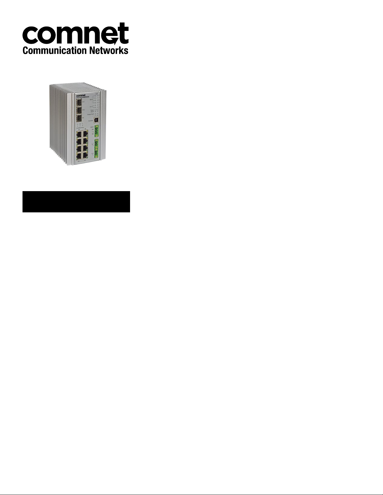
CNGE11FX3TX8MS[POE][HO]
Environmentally Hardened Managed Ethernet Switch
3 SFP + 8 Electrical Ports with Optional 30 or 60 Watt PoE
This guide serves the following
ComNet Model Numbers:
CNGE11FX3TX8MS
CNGE11FX3TX8MSPOE
CNGE11FX3TX8MSPOEHO
The ComNet CNGE11FX3TX8MS[POE][HO] has three 100/1000Base-FX SFP ports
and eight 10/100/1000Base-TX ports. Two of the SFP ports support 2.5 Gbps
SFPs for high speed communication in bandwidth intensive applications. All SFP
ports utilize ComNet SFP modules for fiber and connector type and distance. The
IEEE802.3-compliant unit offers multiple Ethernet redundancy protocols (MSTP/RSTP/
STP/ERPS (G.8032)) which protect your applications from network interruptions or
temporary malfunctions by redirecting transmission within the network. The switch
provides advanced IP-based management that can limit the maximum bandwidth
for each connected IP device, allowing the user to adjust usage. Two models are
available which supply Power over Ethernet (PoE). The CNGE11FX3TX8MSPOE
model provides eight electrical ports supporting up to thirty watts of power. On the
CNGE11FX3TX8MSPOEHO model, four of the eight PoE ports can support up to sixty
watts of PoE power. All PoE ports are IEEE802.3at compliant.
Rev. 11.6.17
Page 2

QUICK START GUIDE CNGE11FX3TX8MS[POE][HO]
Contents
Regulatory Compliance Statement 3
Warranty 3
Disclaimer 3
Safety Information 4
Hardware Installation 5
Installing the Switch on DIN-Rail 5
Wall Mounting Installation 7
Hardware Overview 8
Power Supply 9
Front Panel LEDs 9
POEHO 60 W PoE Model 9
WEB Management 10
TECH SUPPORT: 1.888.678.9427
QSG_CNGE11FX3TX8MS[POE][HO]_REV– Rev. 11.6.17 PAGE 2
Page 3

QUICK START GUIDE CNGE11FX3TX8MS[POE][HO]
Regulatory Compliance Statement
Product(s) associated with this publication complies/comply with all applicable regulations. Please
refer to the Technical Specifications section for more details.
Warranty
ComNet warrants that all ComNet products are free from defects in material and workmanship
for a specified warranty period from the invoice date for the life of the installation. ComNet will
repair or replace products found by ComNet to be defective within this warranty period, with
shipment expenses apportioned by ComNet and the distributor. This warranty does not cover
product modifications or repairs done by persons other than ComNet-approved personnel, and
this warranty does not apply to ComNet products that are misused, abused, improperly installed,
or damaged by accidents.
Please refer to the Technical Specifications section for the actual warranty period(s) of the
product(s) associated with this publication.
Disclaimer
Information in this publication is intended to be accurate. ComNet shall not be responsible for its
use or infringements on third-parties as a result of its use. There may occasionally be unintentional
errors on this publication. ComNet reserves the right to revise the contents of this publication
without notice.
TECH SUPPORT: 1.888.678.9427
QSG_CNGE11FX3TX8MS[POE][HO]_REV– Rev. 11.6.17 PAGE 3
Page 4

QUICK START GUIDE CNGE11FX3TX8MS[POE][HO]
Safety Information
» Only ComNet service personnel can service the equipment. Please contact ComNet Technical
Support.
» The equipment should be installed in locations with controlled access, or other means of
security, and controlled by persons of authority. When operating at temperatures above 51º C, the
equipment surfaces will be hot to the touch. Installation in restricted access location is required
for this case.
» For POE models requiring a power supply not labeled LPS, the unit should be installed in a
restricted access location using a 60950-1, 2nd Edition + Am. 1 + Am. 2 Certified power supply
rated for the ambient temperature in which it is installed. Total derated power rating should be
greater than the sum of the attached loads plus 15 W for the switch.
» Use CDRH compliant SFP modules when using fiber connectivity with this device.
» When used in Australia or New Zealand, the product is certified for intra building applications
only, and should not be directly connected to network cables with outside plant routing.
TECH SUPPORT: 1.888.678.9427
QSG_CNGE11FX3TX8MS[POE][HO]_REV– Rev. 11.6.17 PAGE 4
Page 5

QUICK START GUIDE CNGE11FX3TX8MS[POE][HO]
Hardware Installation
Installing the Switch on DIN-Rail
Each switch has a Din-Rail kit on the rear panel. The DIN-Rail kit affixes the switch to the DIN-Rail.
TECH SUPPORT: 1.888.678.9427
QSG_CNGE11FX3TX8MS[POE][HO]_REV– Rev. 11.6.17 PAGE 5
Page 6

QUICK START GUIDE CNGE11FX3TX8MS[POE][HO]
It is easy to install the switch on the Din-Rail:
Mount Series on DIN-Rail
Step 1: Tilt the switch and mount the metal spring to DIN-Rail.
Step 2: Push the switch toward the DIN-Rail until you hear the spring snap into place
.
TECH SUPPORT: 1.888.678.9427
QSG_CNGE11FX3TX8MS[POE][HO]_REV– Rev. 11.6.17 PAGE 6
Page 7

QUICK START GUIDE CNGE11FX3TX8MS[POE][HO]
Wall Mounting Installation
Each switch has another installation method for users to fix the switch. A wall mount panel can be
found in the package. The following steps show how to mount the switch on the wall:
Mounting the switch on a wall
Note: For drywall applications where no studs are available, use drywall anchors rated for 50 lbs
or more.
In order to prevent switches from being damaged, use appropriate hardware (not supplied)
for securing the unit to the wall.
#6 screws with at least ½-inch penetration into wood surface recommended.
Step 1: Remove DIN-Rail kit if it is installed.
Step 2: Remove the two screws at the top of the unit’s back panel. Remove only one pair of back
panel screws at time (these hold the back panel in place on the unit).
Step 3: Use the same two screws plus one of the included screws to attach the wall mount panel
to the top set of screw holes as shown in the diagram below.
Step 4: Repeat Steps 2 and 3 to mount the second wall mount panel on the bottom of the unit’s
back panel.
ATTENTION: Do not remove the top and bottom panel screws at the same time, or the back
panel will detach from the unit. Install the wall mount panels one at a time.
When operating at temperatures above 51ºC, the equipment surfaces will be
hot to the touch. Installation in restricted access location is required for this case.
TECH SUPPORT: 1.888.678.9427
QSG_CNGE11FX3TX8MS[POE][HO]_REV– Rev. 11.6.17 PAGE 7
Page 8

QUICK START GUIDE CNGE11FX3TX8MS[POE][HO]
Hardware Overview
Call-out Description
1
2
5
6
7
3
8
4
9
CNGE11FX3TX8MS[POE][HO]
1
1 × 100/1000Base-FX SFP Port
2
2 × 100/1000/2500Base-FX SFP Ports
3
Link/Activity LED Indicators for SFP Ports
4
8 × 10/100/1000Base-TX RJ45 Ports
5
PoE LED Indicators (PoE models only)
6
Alarm and Power LED Indicators
7
USB Console Port
8
Fault Relay 3-Pin Terminal Block Connector
9
Redundant Power 2-Pin Terminal Block Connectors
TECH SUPPORT: 1.888.678.9427
QSG_CNGE11FX3TX8MS[POE][HO]_REV– Rev. 11.6.17 PAGE 8
Page 9

QUICK START GUIDE CNGE11FX3TX8MS[POE][HO]
Power Supply
For CNGE11FX3TX8MS Models, Power Supply must be 12 to 57 VDC @ 15 W max.
For CNGE11FX3TX8MSPOE Model, Power Supply must be 44 to 57 VDC @ 255W max.
For CNGE11FX3TX8MSPOEHO Model, Power Supply must be 44 to 57 VDC @ 375W max.
IMPORTANT SAFEGUARDS:
A) Elevated Operating Ambient - If installed in a closed or multi-unit rack assembly, the operating
ambient temperature of the rack environment may be greater than room ambient. Therefore,
consideration should be given to installing the equipment in an environment compatible with
the maximum ambient temperature (Tma) specified by the manufacturer.
B) Reduced Air Flow - Installation of the equipment in a rack should be such that the amount of air
flow required for safe operation of the equipment is not compromised.
Front Panel LEDs
LED Color Status Description
Alarm Red On Alarm Fault Status has been triggered
Power 1 Alarm Green On Power Input on VIN1 terminal block Input
Red On Power lost to VIN1 terminal block
Power 2 Alarm Green On Power Input on VIN1 terminal block Input
Red On Power lost to VIN2 terminal block
PoE (Power over Ethernet)
30W A Green On MODE A PoE is being supplied on indicated RJ-45 port
30W B Green On MODE B PoE is being supplied on indicated RJ-45 port
Gigabit Ethernet ports
Link Green On Port in Full Duplex mode
Activity Amber Blinking Data transmitted
Gigabit SFP ports
Link/Activity Amber Blinking Data transmitted
POEHO 60 W PoE Model
Port 1 to 4 support both mode A and mode B PoE which is 60 W in total. When a greater than 30
W PoE supported device is connected to ports 1 to 4, both 30 W A and B Indicator LEDs will be
turned on to indicate the high-power application device is connected.
TECH SUPPORT: 1.888.678.9427
QSG_CNGE11FX3TX8MS[POE][HO]_REV– Rev. 11.6.17 PAGE 9
Page 10

QUICK START GUIDE CNGE11FX3TX8MS[POE][HO]
WEB Management
Attention: While installing and upgrading firmware, please remove physical loop connection first.
DO NOT power off equipment while the firmware is upgrading!
Configuration by Web Browser
About Web-based Management
An embedded HTML web site resides in the flash memory on the CPU board. It contains
advanced management features and allows you to manage the switch from anywhere on the
network through a standard web browser such as Microsoft Internet Explorer.
Preparing for Web Management
The default value is as below:
IP Address: 192.168.10.1
Subnet Mask: 255.255.255.0
Default Gateway: 192 .168.10 .254
User Name: admin
Password: admin
System Login
1. Launch web browser.
2. Type ht t p://192 .168 .10.1. Press Enter.
3. The login screen appears.
4. Key in the username and password. The default username and password is admin.
5. Select Enter or OK button, then the main interface of the Web-based management appears.
Warning – Any changes made to the settings will apply only to the current running
configuration of the switch and will be lost in the event of a power cycle.
To save any changes made to persistent memory please go to “Maintenance ¦
Configuration ¦ Save startup-config” to write the changes to the switches startup
configuration.
TECH SUPPORT: 1.888.678.9427
QSG_CNGE11FX3TX8MS[POE][HO]_REV– Rev. 11.6.17 PAGE 10
Page 11

QUICK START GUIDE CNGE11FX3TX8MS[POE][HO]
TECH SUPPORT: 1.888.678.9427
QSG_CNGE11FX3TX8MS[POE][HO]_REV– Rev. 11.6.17 PAGE 11
Page 12

MECHANICAL INSTALLATION INSTRUCTIONS
ComNet Customer Service
Customer Care is ComNet Technology’s global service center, where our
professional staff is ready to answer your questions at any time.
Email ComNet Global Service Center: customercare@comnet.net
3 CORPORATE DRIVE | DANBURY, CT 06810 | USA
T: 203.796.5300 | F: 203.796.5303 | TECH SUPPORT: 1.888.678.9427 | INFO@COMNET.NET
8 TURNBERRY PARK ROAD | GILDERSOME | MORLEY | LEEDS, UK LS27 7LE
T: +44 (0)113 307 6400 | F: +44 (0)113 253 7462 | INFO-EUROPE@COMNET.NET
© 2017 Communications Networks Corporation. All Rights Reserved. “ComNet” and the “ComNet Logo” are registere d trademarks of Communication Networks, L LC.
 Loading...