

Page 1
GROUP S.P.A.
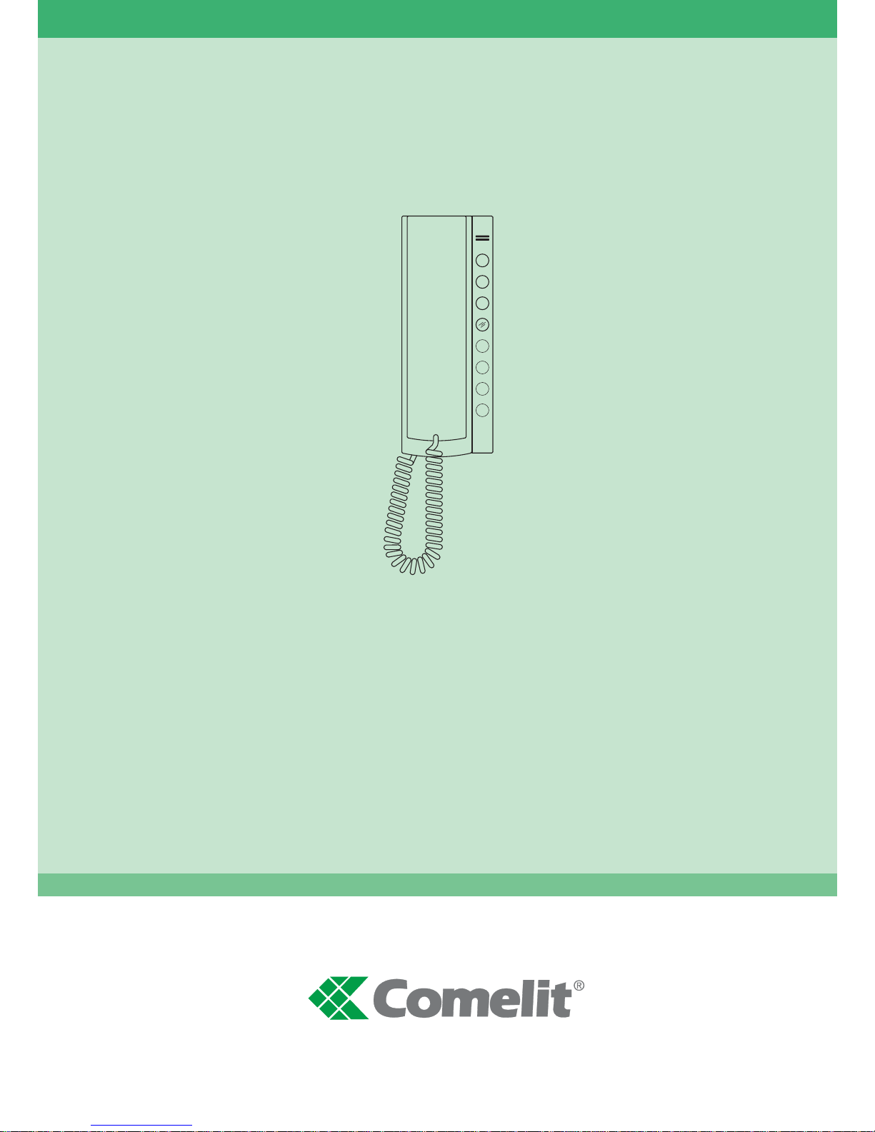
Citofono Art. 2410W/2B
Telephone Art. 2410W/2B
Combiné parlophonique Art. 2410W/2B
Deurtelefoon Art. 2410W/2B
Innenstelle Art. 2410W/2B
Telefone Art. 2410W/2B
Telefonillo Art. 2410W/2B
01-2006
FT SB2 09
TECHNICAL
SHEET
FOGLIO
TECNICO
FEUILLE
TECHNIQUE
TECHNIKBLATTTECHNISCHE
HANDLEIDING
HOJA
TÉCNICA
FOLHETO
TÉCNICO
GBIF DNL EP
Page 2
GROUP S.P.A.
FT SB2 09
2
Avvertenze:
• Effettuare l’installazione seguendo scrupolosamente le istruzioni fornite dal costruttore ed in conformità alle norme vigenti.
• Tutti gli apparecchi devono essere destinati esclusivamente all’uso per cui sono stati concepiti. Comelit Group S.p.A. declina ogni responsabilità per un utilizzo improprio degli
apparecchi, per modifiche effettuate da altri a qualunque titolo e scopo, per l’uso di accessori e materiali non originali.
• Tutti i prodotti sono conformi alle prescrizioni delle direttive CEE 73/23-89/336 e ciò è attestato dalla presenza della marcatura CE sugli stessi.
• Evitare di porre i fili di montante in prossimità di cavi di alimentazione (230/380V).
Instructions:
• Install the equipment by carefully following the instructions given by the manufacturer and in compliance with the legislation in force.
• All the equipment must only be used for the purpose it was built for. Comelit Group S.p.A. declines any responsibility for improper use of the apparatus, for modifications made
by others under any title or scope, and for the use of accessories and materials which are not the original ones.
• All the products comply with the requirements of the EEC 73/23-89/336 directives. This is proved by the CE mark on the products .
• Do not run the riser wires in proximity of the power supply cables (230/380V).
Instructions
• Effectuer l’installation en suivant scrupuleusement les instructions fournies par le constructeur et conformément aux normes en vigueur.
• Tous les appareils doivent être strictement destinés à l’emploi pour lequel ils ont été conçus. Comelit Group S.p.A. décline toute responsabilité en cas de mauvais usage
des appareils, pour des modifications effectuées par d’autres personnes pour n’importe quelle raison et pour l’ utilisation d’accessoires non fournis par nous.
• Tous les produits sont conformes aux prescriptions demandées par les normes CEE 73/23-89/336. Cela est attesté par la présence du marque CE sur les produits.
• Eviter de placer les fils de montant à proximité des câbles d’alimentation (230/380 V).
Waarschuwingen
• Volg de instructies van de fabrikant nauwkeurig en installeer de materialen volgens de plaatselijk geldende normen en wetgeving.
•Alle componenten mogen alleen gebruikt worden voor de doeleinden waarvoor ze zijn ontworpen. Comelit Group S.p.A. is niet verantwoordelijk bij een onjuist gebruik van
de apparatuur, of modificaties welke aangebracht zijn zonder voorafgaande toestemming, evenals het gebruik van accessoires welke niet door de fabrikant zijn aangeleverd.
• Alle producten voldoen aan de eisen van de richtlijn EEC 73/23-89/336. Die wordt bevestigd door het CE label op de producten.
• Monteer de aders (bekabeling) niet in de nabijheid van voedingskabels (230/380V).
Hinweise
• Die Installationen sind nach den Anweisungen des Herstellers und gemäß den geltenden Vorschriften gewissenhaft auszuführen.
• Alle Geräte dürfen ausschließlich nur zu dem Zweck eingesetzt werden, für den sie entwickelt worden sind. Comelit Group S.p.A. lehnt die Haftung für unsachgemässe
Verwendung der Produkte oder für unautorisierte Veränderung von Produkten, sowie für alle Produkte, welche nicht von der Firma geliefert wurden, ab.
• Alle Produkte entsprechen den Richtlinien EG-73/23 und EG-89/336. Die Übereinstimmung der Produkte mit den genannten Richtlinien wird durch das Vorhandensein der
CE-Markierung auf den Produkten beglaubigt.
• Die Drähte der Steigleitungen nicht in der Nähe der Stromkabel (230/380 V) verlegen.
Instruções
• Instale o equipamento cuidadosamente, seguindo as instruções dadas pelo fabricante que estão de acordo com a legislação em vigor.
• Todo o equipamento deve ser usado para o fim para que foi construído. Comelit Group S.p.A. declina todas as responsabilidades pelo uso impróprio do equipamento, quaisquer
modificações efectuadas por qualqer que seja o motivo sem autorização prévia, como também pelo uso de ferramentas que não tenham sido originariámente fornecidas pela
Comelit Group S.p.a.
• Todos os produtos cumprem com as normas das directivas EEC 73/23-89/336. Isto encontra-se provado pela marcação CE posta em todos os produtos.
• Não instalar os condutores da coluna montante na proximidade dos cabos de alimentação (230/380V).
Advertencias
• Efectuar la instalación siguiendo atentamente las instrucciones suministradas por el constructor y conformes con las normas vigentes.
• Todos los aparatos deben estar destinados exclusivamente al uso para el cual han sido construidos. Group S.p.A. declina toda responsabilidad por el uso impropio de los
aparatos, por cambios efectuados por terceros para cualquier título o finalidad, por el uso de accesorios y materiales no originales.
• Todos los productos son conformes a los requisitos de las directivas CEE 73/23-89/336 y da prueba de ello la presencia de la marca CE en los mismos.
• Evitar poner los cables de columna cerca de los cables de alimentación (230/380V).
I
GB
F
D
NL
P
E
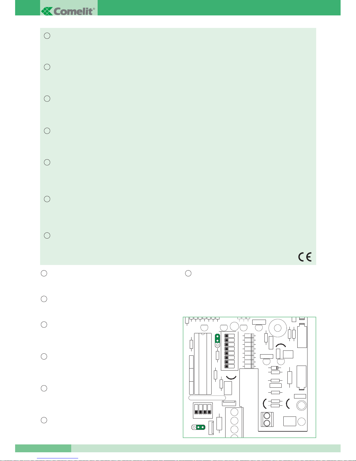
NOTA: PER UTILIZZARE IL CITOFONO ART. 2410W/2B IN
IMPIANTI SIMPLEBUS1 E BRAVO KIT È NECESSARIO:
1) spostare jumper CV1A in posizione 1
2) spostare jumper JP1 in posizione 1
CV3
JP1
21
21
CV2
CV5CV4
CV1A
1234
L +
L -
I
NOTE: TO USE TELEPHONE ART. 2410W/2B IN SIMPLEBUS1
AND BRAVO KIT SYSTEMS, IT IS NECESSARY TO:
1) move jumper CV1A to position 1
2) move jumper JP1 to position 1
GB
NOTA:
PARA USAR O TELEFONE ART. 2410W/2B EM INSTALAÇÕES
SIMPLEBUS1 E BRAVO KIT É NECESSÁRIO:
1) deslocar o jumper CV1A na posição 1
2) deslocar o jumper JP1 na posição 1
P
NOTA: PARA UTILIZAR EL TELEFONILLO ART. 2410W/2B
EN INSTALACIONES SIMPLEBUS1 Y BRAVO KIT
ES NECESARIO:
1) desplazar el jumper CV1A a la posición 1
2) desplazar el jumper JP1 a la posición 1
E
NOTE: POUR UTILISER LE COMBINE PARLOPHONIQUE
ART. 2410W/2B DANS LES INSTALLATIONS SIMPLEBUS1 ET BRAVO KIT:
1) déplacer le jumper CV1A sur 1
2) déplacer le jumper JP1 sur 1
F
BELANGRIJK: ALS DE DEURTELEFOON ART. 2410W/2B IN
EEN SIMPLEBUS1 SYSTEEM WORDT TOEGEPAST
IS HET NOODZAKELIJK OM:
1) jumper CV1A op positie 1 te zetten
2) jumper JP1 op positie 1 te zetten
NL
ANMERKUNG: FÜR DIE VERWENDUNG DER INNENSTELLE
ART. 2410W/2B IN SIMPLEBUS1 UND
BRAVO KIT IST FOLGENDES ERFORDERLICH:
1) Jumper CV1A auf Position 1 stellen
2) Jumper JP1 auf Position 1 stellen
D
Page 3
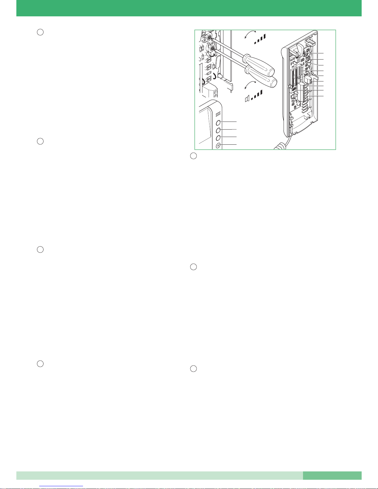
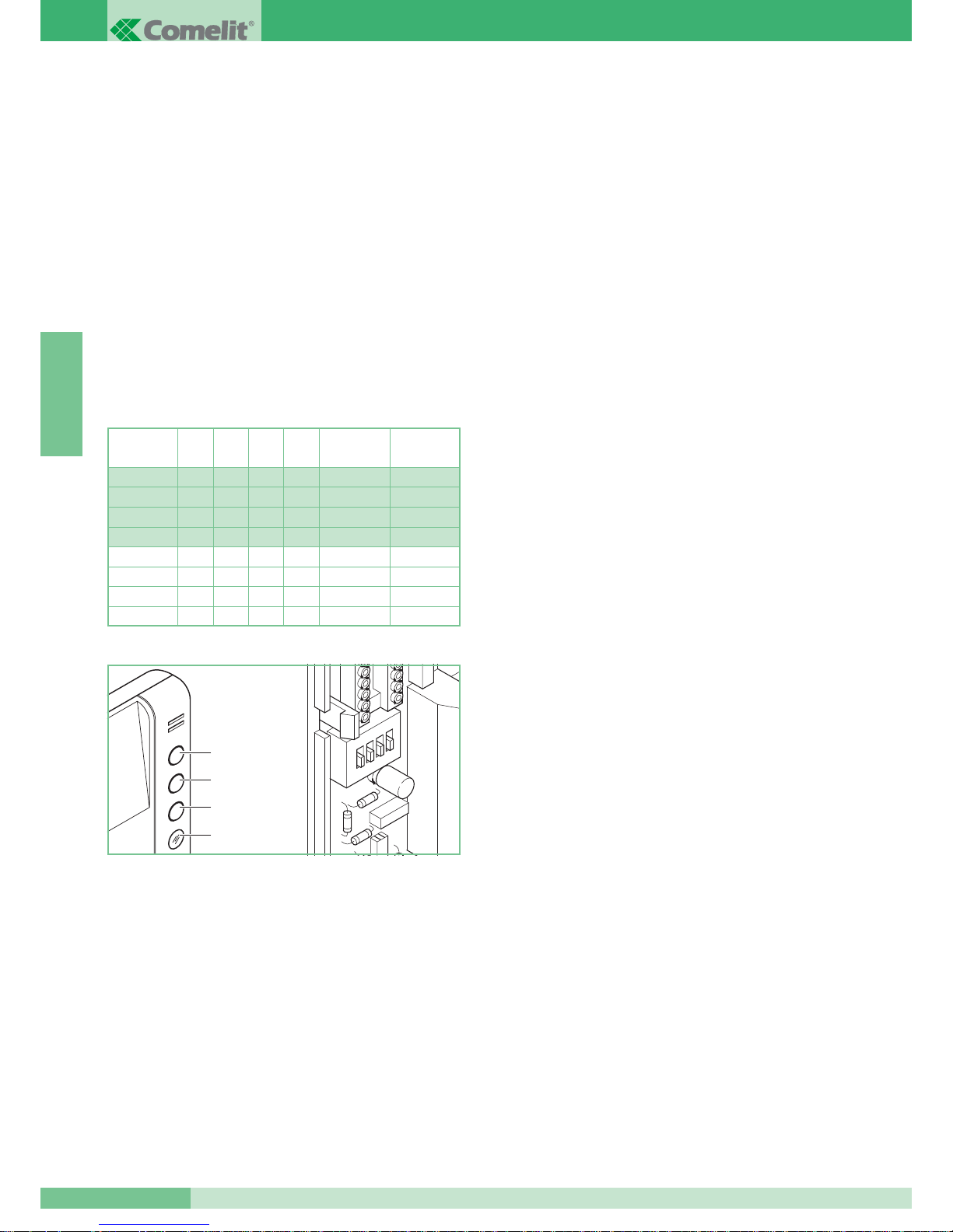
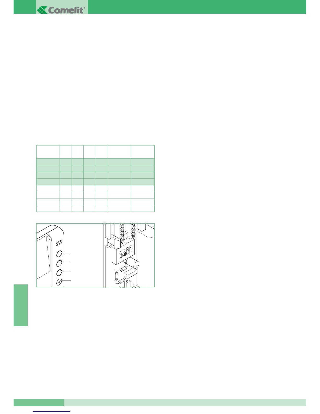
Caratteristiche tecniche:
1. Pulsante apriporta.
2. Pulsante 2 (vedi Tab.1 per funzioni impostabili)/pulsante per usi
vari presente in morsettiera (P1 C1).
3. Pulsante 3 (vedi Tab.1 per funzioni impostabili).
4. LED di segnalazione attivazione Privacy/Occupato
5. Trimmer regolazione volume microfono.
6. Trimmer regolazione volume suoneria.
7. Morsetti connessione impianto.
L L connessione alla linea bus.
CFP CFP ingresso chiamata da piano.
P1 C1 pulsante normalmente dedicato a servizi vari.
Per avere contatto pulito NO tagliare i cavallotti CV2 e CV3.
S+ S- morsetti per dispositivo ripetizione di chiamata.
L+ L- morsetti per alimentazione LED
8. Dip switches S1 per impostazione codice utente.
9. Cavallotto CV2
10. Cavallotto CV3
11.
Dip switches S2 per impostazione funzioni pulsanti (vedi Tab.1).
12.
CV4 e CV5 cavallotti da tagliare quando si alimenta il LED
separatamente.
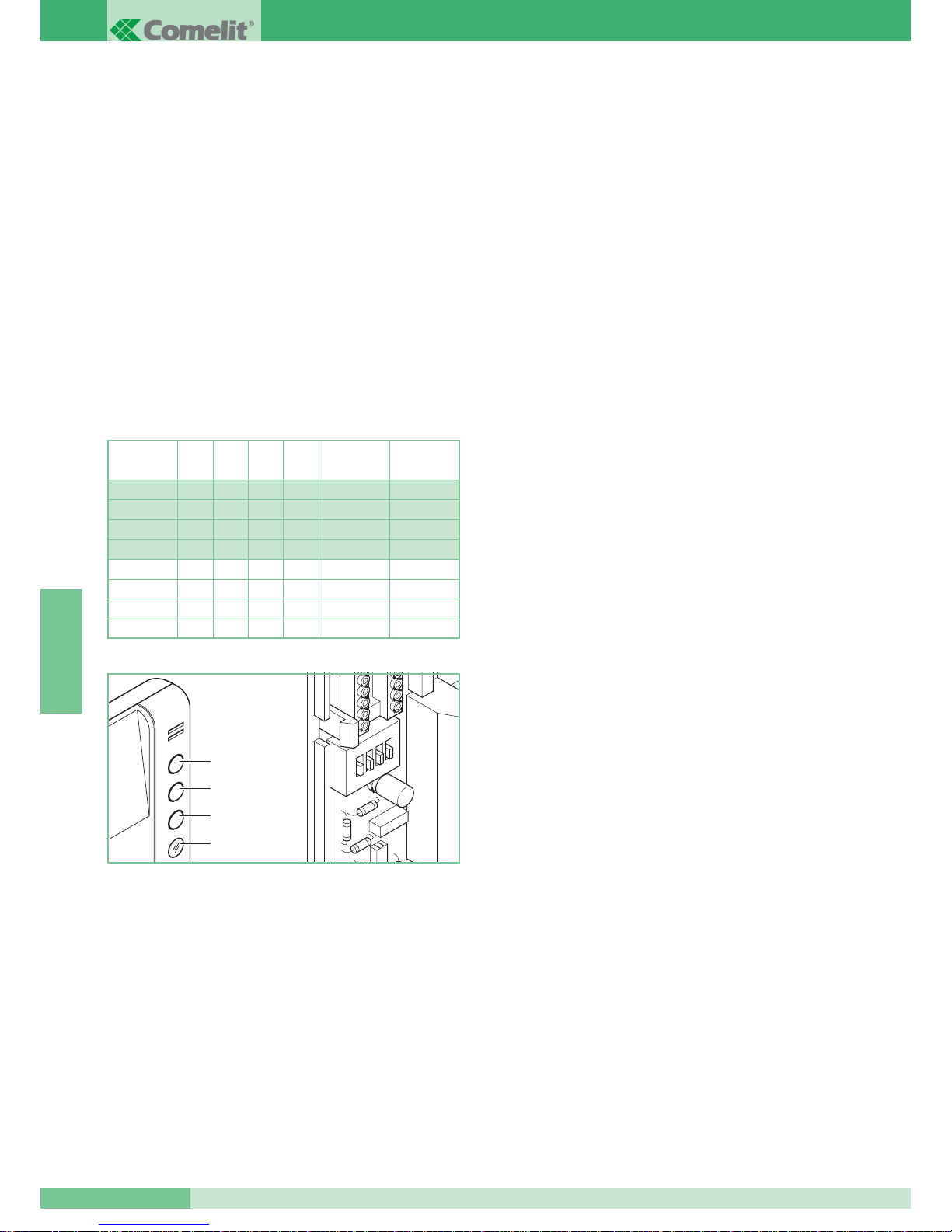
Technical characteristics:
1. Door-opening pushbutton.
2. Pushbutton 2 (see table1 for settable functions)/pushbutton for
various uses present on the terminal board (P1 C1).
3. Pushbutton 3 (see table1 for settable functions).
4. LED signalling activation of Privacy/Engaged
5. Microphone volume adjustment trimmer.
6. Call volume adjustment trimmer.
7. System connection terminals.
L L connection to the bus line.
CFP CFP floor door call input.
P1 C1 pushbutton normally dedicated to various services.
To have a clean NO contact, cut jumpers CV2 and CV3.
S+ S- terminals for call repetition device.
L+ L- terminals for LED power supply.
8. Dip switches S1 for setting user code.
9. Jumper CV2
10. Jumper CV3
11. Dip switches S2 for setting pushbutton functions (see table1).
12. Jumpers CV4 and CV5 to be cut when the LED is supplied
separately.
Caractéristiques techniques:
1. Bouton ouvre-porte.
2. Bouton 2 (voir Tab.1 pour les fonctions programmables)/bouton
pour usages divers présent dans la boîte à bornes (P1 C1).
3. Bouton 3 (voir Tab.1 pour les fonctions programmables).
4. Led de signalisation activation Privacy/Occupé
5. Trimmer de réglage du volume du micro.
6. Trimmer de réglage du volume de la sonnerie.
7. Bornes de connexion à l’installation.
L L connexion à la ligne bus.
CFP CFP entrée appel palier.
P1 C1 bouton normalement destiné à des services divers.
Pour avoir un contact libre NO couper les cavaliers CV2 et CV3.
S+ S- bornes pour le dispositif de répétition de l’appel.
L+ L- bornes pour alimentation led
8. Dip-switch S1 pour la programmation du code utilisateur.
9. Cavalier CV2
10. Cavalier CV3
11. Dip-switch S2 pour la programmation des fonctions des boutons
(voir Tab.1).
12. CV4 et CV5 cavaliers à couper lorsque la led est alimentée
séparément.
Technische gegevens:
1. Deuropener drukknop
2. Drukknop 2(zie tabel 1 voor de instelbare functies)/ drukknop voor
vrij gebruik (P1 C1)
3. Drukknop 3(zie tabel 1 voor de instelbare functies)
4. LED voor signalering van privacy / bezet.
5. Microfoon volume-instelling.
6. Belvolume instelling.
7. Connector voor aansluiting op het systeem
LL aansluiting van de buslijn.
CFP CFP ingang voor etagebel drukknop.
P1 C1 Drukknop uitgang voor vrij gebruik. Knip de bruggen CV2 en
CV3 door voor een potentieelvrij NO contact.
S+ S- uitgang voor extra bel.
L+ L- Aansluitingen voor voeding LED.
8. Dipswitch voor het instellen van de gebruikerscode.
9. Jumper CV2
10. Jumper CV3
11. Dipswitch voor de drukknop functie-instelling(zie tab.1)
12. Jumper CV4 en CV5 dienen doorgeknipt te worden als de LED
separaat gevoed wordt.
Technische Eigenschaften
1. Türöffnertaste.
2. Taste 2 (siehe Tab. 1 für einstellbare Funktionen)/Taste für
verschiedene Anwendungen auf der Klemmleiste (P1 C1).
3. Taste 3 (siehe Tab.1 für einstellbare Funktionen).
4. Anzeige-Led Aktivierung Privacy/Besetzt
5. Trimmer zum Einstellen der Lautstärke des Mikrofons.
6. Trimmer zum Einstellen der Lautstärke des Ruftons.
7. Klemmen zum Anschluss an die Anlage.
L L Anschluss an die Busleitung.
CFP CFP Eingang des Ruftons von der Etage aus.
P1 C1 Taste normalerweise für verschiedene Funktionen
vorgesehen. Um einen sauberen Kontakt NO zu erhalten, die
Brücken CV2 und CV3 durchschneiden.
S+ S- Klemmen für die Rufwiederholungsvorrichtung.
L+ L- Klemmen für LED-Versorgung
8. DIP-Schalter S1 zur Einstellung des Anwendercodes.
9. Brücke CV2
10. Brücke CV3
11.
DIP-Schalter S2 zur Einstellung der Tasterfunktionen (siehe Tab.1).
12. Brücken CV4 und CV5 müssen bei getrennter Versorgung der LED
durchtrennt werden
Características técnicas:
1. Botão de abertura porta.
2. Botão 2 (ver Tab. 1 para funções configuráveis)/botão para usos
diversos presentes na régua de bornes (P1 C1).
3. Botão 3 (ver Tab. 1 para funções configuráveis).
4. LED de sinalização activação Privacidade/Ocupado
5. Trimmer de regulação do volume do microfone.
6. Trimmer de regulação do volume do toque.
7. Bornes de ligação da instalação.
L L enlace à linha bus.
CFP CFP entrada chamada pelo andar.
P1 C1 botão normalmente dedicado a serviços diversos.
Para ter contacto limpo NO cortar os conectores CV2 e CV3.
S+ S- bornes para dispositivo repetição de chamada.
L+ L- bornes para alimentação LED
8. Dip switches S1 para a programação do código utente.
9. Conector CV2
10. Conector CV3
11.
Dip switches S2 para configuração de funções dos botões (ver Tab.1).
12. CV4 e CV5 conectores para cortar quando se alimenta o LED separadamente
Características técnicas:
1. Pulsador abre puerta.
2. Pulsador 2 (véase Tabl. 1 para funciones programables)/pulsador
para los diferentes usos presente en la caja de bornas (P1 C1).
3. Pulsador 3 (véase Tabl.1 para funciones programables).
4. LED de señalización activación Privado/Comunicando
5. Trimmer regulación del volumen micrófono.
6. Trimmer regulación del volumen timbre.
7. Bornas conexión instalación:
L L conexión a la línea bus .
CFP CFP entrada llamada del piso.
P1 C1 pulsador normalmente dedicado a servicios diferentes.
Para obtener un contacto limpio NO cortar los pernos CV2 y CV3.
S+ S- bornas para dispositivo de repetición de llamada.
L+ L- bornas para alimentación LED
8. Dip switches S1 para programación código usuario.
9. Conector CV2.
10. Conector CV3
11.
Dip switches S2 para programación funciones pulsadores (véase Tabl.1).
12.
CV4 y CV5 conectores para cortar cuando se alimenta el LED separadamente
5
6
1
2
+
-
+
-
MIC
3
4
11
9
8
12
7
10
7
FT SB2 09
3
FT SB2 09
GB
F
D
NL
P
E
I
Page 4

GROUP S.P.A.
FT SB2 09
4
ITALIANO
Citofono Art. 2410W/2B
Citofono della serie Okay di dimensioni 85x223x65 mm.
Il citofono è fornito oltre che di pulsante apriporta, di un LED per
segnalazione e di due pulsanti le cui funzioni sono impostabili a seconda
dell’impianto in cui viene inserito. E’ equipaggiato di serie di funzione
Chiamata da piano (vedi variante A) e di Ripetizione di chiamata (vedi
variante B). È possibile inserire sino a tre citofoni con lo stesso codice
utente nel medesimo impianto.
Per impostazione codice utente vedi “Programmazione citofono
Art. 2408W/A, 2428W/A e staffa Art. 4714W/2” su MT/SB2/01 o FT/SB/07.
E’ utilizzabile sia su impianti Simplebus1 che su impianti Simplebus2. L’articolo,
da fabbrica, è impostato per essere utilizzato su impianti Simplebus2.
Per utilizzare il citofono Art. 2410W/2B in impianti Simplebus1 e Bravo
kit vedi nota pag. 2.
L’Art. 2410W/2B permette di sfruttare le funzioni Privacy, Dottore, Attuatore
e Chiamata a Centralino su impianti tipo Simplebus1 e Simplebus2 e le
funzioni Privacy, Dottore, Attuatore, intercomunicante Monofamiliare e
Bifamiliare sugli impianti tipo Bravo kit.
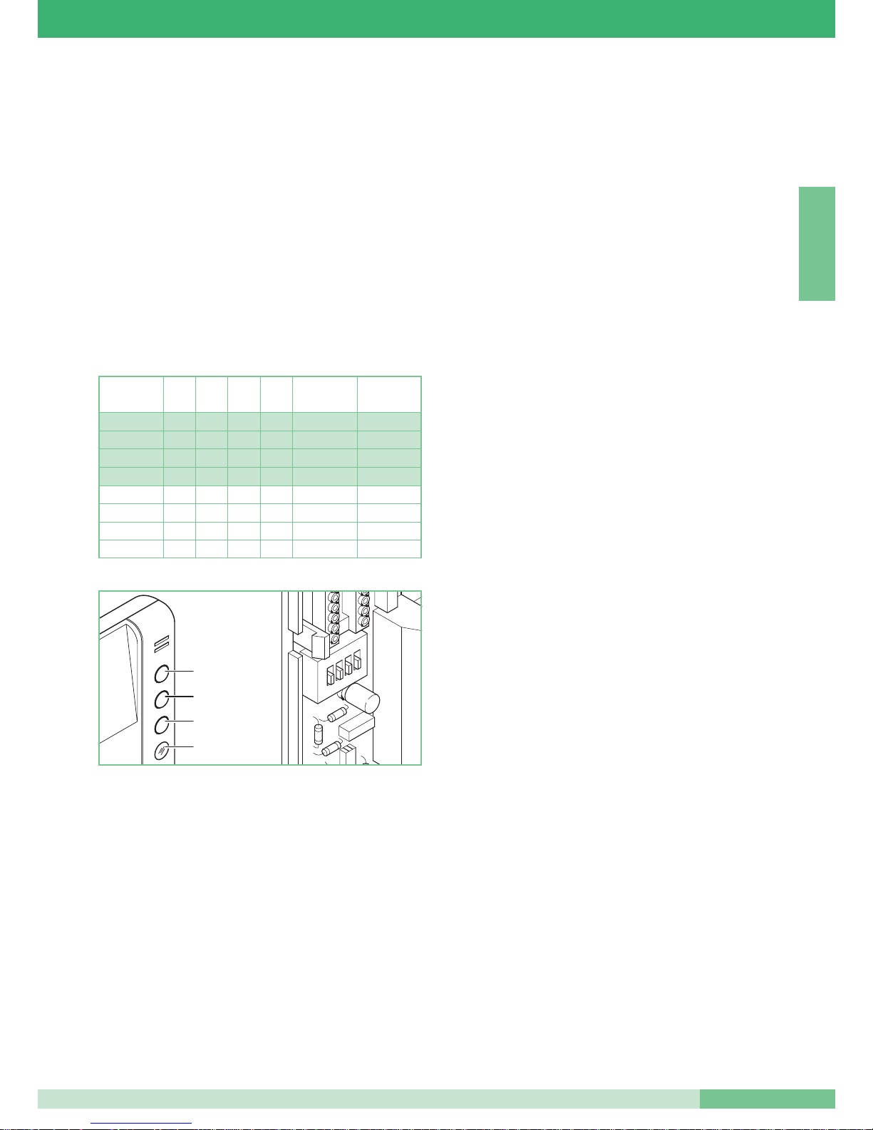
Le impostazioni del Dip switches S2 per assegnare le funzioni ad ogni
pulsante seguono la regola di Tab. 1.
La funzione
Privacy, se impostata, permette di disattivare momentaneamente
la suoneria del citofono su chiamata da posto esterno, e su chiamata da
centralino di portineria.
La funzione Dottore oltre a disattivare la suoneria del citofono come nella
funzione Privacy, permette l’azionamento automatico dell’apriporta su
chiamata al codice utente del citofono da parte del posto esterno.
L’abilitazione o la disabilitazione delle funzioni Privacy e Dottore avviene
premendo per
2 secondi il pulsante 3 del Citofono; l’abilitazione inoltre è
indicata dall’accensione del LED di segnalazione. Nel caso di più utenti
con stesso codice utente impostare la funzione Dottore su uno solo degli
apparecchi abilitati a questa funzione. Per l’inserimento dell’Art.2410W/2B
in impianti Simplebus e Bravo kit vedi schemi nella sez.A: SB/I1 - SB2/01
- SB/J1.
La funzione chiamata
Attuatore permette di attivare il relè a bordo
dell’Art. 1256; impostare questa funzione solo se presente un Art. 1256 in
funzione E (attivazione su pulsante attuatore).
Per impostare il modulo relè attuatore Art. 1256 in modo che si attivi su
comando attuatore vedi foglio tecnico FT/SB2/02 allegato alla confezione.
La chiamata attuatore si effettua premendo il pulsante 2 o il pulsante 3 a
seconda dell’impostazione del Dip switches S2 (vedi Tab.1).
Per l’inserimento dell’Art. 2410W/2B in impianti Simplebus e Bravo kit vedi
schemi nella sez. A: SB/I1 - SB2/01 - SB/J1.
La funzione chiamata
Centralino permette di effettuare la chiamata a
centralino di portineria Art. 1998 negli impianti provvisti di centralino. Negli
impianti non forniti di centralino Art. 1998 la stessa funzione chiamata a
centralino è utilizzabile per attivare il relè a bordo dell’Art.1256. Per impostare
il modulo relè attuatore Art. 1256 in modo che si attivi su comando chiamata
centralino vedi foglio tecnico FT/SB2/02 allegato alla confezione.
La chiamata centralino si effettua premendo il pulsante 2 del citofono se
opportunamente impostato il Dip switches S2 (vedi Tab.1).
Per l’inserimento dell’Art. 2410W/2B in impianti Simplebus vedi schemi
nella sezA: SB/I1 - SB2/01 - SB/J1.
La funzione intercomunicante
Monofamiliare è utilizzabile solo negli
impianti Bravo kit. Essa permette la comunicazione audio tra due unità
(videocitofono o citofono) impostate sul medesimo codice utente. La
pressione di
P2 o P3 attiva la chiamata verso le restanti postazioni della
medesima unità familiare. Il ricevente della chiamata alzando la cornetta
entra così in comunicazione con il chiamante. Riagganciando la cornetta la
comunicazione viene terminata. Una chiamata da posto esterno è comunque
sempre prioritaria rispetto ad una comunicazione intercomunicante.
In questo caso gli utenti che si trovano già in conversazione sentiranno in
cornetta un tono simile a quello di chiamata se quest’ultima è indirizzata a
loro o un triplice tono di segnalazione in caso contrario.
Per rispondere alla chiamata da posto esterno è sufficiente sollevare la
cornetta da qualunque apparecchio libero o riagganciare e sollevare la
cornetta da un apparecchio impegnato nella comunicazione
intercomunicante. L’attivazione della comunicazione con il posto esterno
interrompe la conversazione intercomunicante precedentemente in corso.
Una chiamata intercomunicante non è prioritaria rispetto ad una
conversazione/chiamata con il posto esterno. In questo caso, durante un
tentativo di chiamata intercomunicante, il LED lampeggerà per alcuni
secondi per segnalare che il sistema è occupato.
La chiamata intercomunicante Monofamiliare si effettua premendo il
pulsante 2 o il pulsante 3 a seconda dell’impostazione del Dip switches S2
(vedi Tab.1). Per l’inserimento dell’Art.2410W/2B in impianti Bravo kit vedi
schema SB/J1 nella sezA.
La funzione intercomunicante
Bifamiliare è utilizzabile solo negli impianti
Bravo kit: essa permette la comunicazione audio tra due unità
(Videocitofono o citofono) che non sono impostate sullo stesso codice
utente. La pressione del Pulsante P3 attiva la chiamata verso le postazioni
dell’altra unità familiare. Il ricevente della chiamata alzando la cornetta
entra così in
comunicazione con il chiamante. Riagganciando la cornetta la
comunicazione
viene terminata.
Una chiamata da posto esterno è comunque sempre prioritaria rispetto ad
una comunicazione intercomunicante. In questo caso gli utenti che si
trovano già in conversazione sentiranno in cornetta un tono simile a quello
di chiamata se quest’ultima è indirizzata a loro o un triplice tono di
segnalazione in caso contrario. Per rispondere alla chiamata da posto
esterno è sufficiente sollevare la cornetta da qualunque apparecchio libero
o riagganciare e sollevare la cornetta da un apparecchio impegnato nella
comunicazione intercomunicante.
L’attivazione della comunicazione con il posto esterno interrompe la
conversazione intercomunicante precedentemente in corso.
Una chiamata intercomunicante non è prioritaria rispetto ad una
conversazione/chiamata con il posto esterno. In questo caso, durante un
tentativo di chiamata intercomunicante, il LED lampeggerà per alcuni
secondi per segnalare che il sistema è occupato.
La chiamata intercomunicante Bifamiliare si effettua premendo il pulsante 3
se opportunamente impostato il Dip switches S2 (vedi Tab.1).
Per l’ inserimento dell’Art.2410W/2B in impianti Bravo kit vedi Schema
SB/J1 nella sez. A.
S2
1
2
3
4
Tab. 1
Pulsante 3
Pulsante 2
Pulsante
apriporta
Led di
segnalazione
Corrispondenza
con BRAVO KIT
Config. 0
DIP 1 DIP 2 DIP 3 DIP 4 Pulsante 2 Pulsante 3
Config. 1
Config. 2
Config. 3
0
0
1
0
0
1
1
1
1
0
0
1
0
0
1
1
0
1
1
1
0
0
0
1
0
0
0
0
0
0
0
0
Attuatore
Attuatore
Attuatore
Monofamiliare
Centralino
Centralino
Attuatore
Centralino
Privacy
Monofamiliare
Bifamiliare
Bifamiliare
Privacy
Dottore
Dottore
Attuatore
Page 5
FT SB2 09
5
FT SB2 09
ENGLISH
Telephone Art. 2410W/2B
Okay series telephone - dimensions: 85x223x65 mm.
The telephone is fitted with door-opening pushbutton, signalling LED and
two pushbuttons whose functions can be set according to the system it is
inserted in. As standard it is fitted with floor door call function (see variant
A) and call repetition (see variant B). Up to three telephones with the same
user code can be inserted in the same system.
To set the user code, see “Programming telephone Art. 2408W/A, 2428W/A
and bracket Art. 4714W/2” in MT/SB2/01 or FT/SB/07.
It can be used either in Simplebus1 systems or in Simplebus2 systems. The
article is set in the factory to be used in Simplebus2 systems.
To use the telephone Art. 2410W/2B in Simplebus1 and Bravo kit
systems, see the note on page 2.
Art. 2410W/2B allows the Privacy, Doctor, 1256 relay and Porter
switchboard Call functions to be used in Simplebus1 and Simplebus2 type
systems and the Privacy, Doctor, 1256 relay, Single-family and Two-family
intercom functions in Bravo kit type systems.
The S2 Dip switch settings to assign the functions to each pushbutton follow
the rules given in Table 1.
The Privacy function, when set, means the telephone bell can be
momentarily disabled on a call from the external unit, on a call from the
porter switchboard.
Apart from disabling the telephone bell as in the Privacy function, the
Doctor function also allows automatic door-opening activation on a call to
the telephone from the external unit.
Enabling or disabling the Privacy and Doctor functions is carried out by
pressing
pushbutton 3 of the Telephone for 2 seconds. Enablement is
also indicated by the signalling LED lighting up. When there are several
users with the same user code, set the Doctor function on only one of the
units enabled for this function.
To insert Art.2410W/2B in Simplebus and Bravo kit systems, see the
diagrams in sect. A: SB/I1 - SB2/01 - SB/J1.
The
1256 relay function allows the relay on board Art. 1256 to be activated.
Only set this function if an Art. 1256 is present in function E (activation on
apartment unit pushbutton).
To set the actuator relay module Art. 1256 so that it is activated on the
actuator command, please see technical sheet FT/SB2/02 enclosed with
the pack.
The 1256 activation is made by pressing pushbutton 2 or pushbutton 3
according to the S2 Dip switch setting (see Table1).
To insert Art. 2410W/2B in Simplebus and Bravo kit systems, see the
diagrams in sect. A: SB/I1 - SB2/01 - SB/J1.
The
Porter switchboard call function allows the call to porter switchboard
Art. 1998 to be made in systems provided with a porter switchboard. In the
systems not provided with a porter switchboard Art. 1998, the same call
function to a porter switchboard can be used to activate the relay on board
Art.1256. To set the relay Art. 1256 so that it is activated on porter
switchboard call command, please see technical sheet FT/SB2/02 enclosed
with the pack.
The porter switchboard call is made by pressing pushbutton 2 of the
telephone if the S2 Dip switches are suitably set (see Table1).
To insert Art. 2410W/2B in Simplebus systems, see the diagrams in sect. A:
SB/I1 - SB2/01 - SB/J1.
The
Single-family intercom function can only be used in Bravo kit systems.
It allows audio communication between two units (video entry phone or
telephone) set to the same user code. Pressing
P2 or P3 activates the call
to the remaining stations of the same family unit. By lifting the handset, the
receiver of the call communicates with the caller. The communication is
ended by hanging up the handset. In any case, a call from the external unit
always takes priority over an intercom communication.
In this case, the users who are already speaking will hear a tone similar to
the call tone in the handset if the latter is addressed to them or otherwise a
triple signalling tone.
To answer the call from the external unit, simply lift the handset of any free
unit or hang up and lift the handset of unit engaged in an intercom
communication. Activation of communication with the external unit
interrupts the intercom conversation which was previously in progress.
An intercom call does not have priority over a conversation/call with the
external unit. In this case, during an intercom call attempt, the LED will flash
for a few seconds to signal that the system is engaged.
The Single-family intercom call is made by pressing P2 or P3 according to
the S2 Dip switch setting (see Table1). To insert Art. 2410W/2B in Bravo
kit systems, see diagram SB/J1 in sect. A.
The
Two-family intercom function can only be used in Bravo kit systems: it
allows audio communication between two units (video entry phone or
telephone) which are not set to the same user code. Pressing Pushbutton
P3 activates the call towards the stations of the other family unit. By lifting
the handset, the receiver of the call communicates with the caller. The
communication is ended by hanging up the handset.
In any case, a call from the external unit always takes priority over an
intercom communication. In this case, the users who are already speaking
will hear a tone similar to the call tone in the handset if the latter is
addressed to them or otherwise a triple signalling tone. To answer the call
from the external unit, simply lift the handset of any free unit or hang up and
lift the handset of unit engaged in an intercom communication.
Activation of communication with the external unit interrupts the intercom
conversation which was previously in progress.
An intercom call does not have priority over a conversation/call with the
external unit. In this case, during an intercom call attempt, the LED will flash
for a few seconds to signal that the system is engaged.
The Two-family intercom call is made by pressing pushbutton 3 if the S2 Dip
switches are suitably set (see Table1).
To insert Art. 2410W/2B in Bravo kit systems, see Diagram SB/J1 in sect. A.
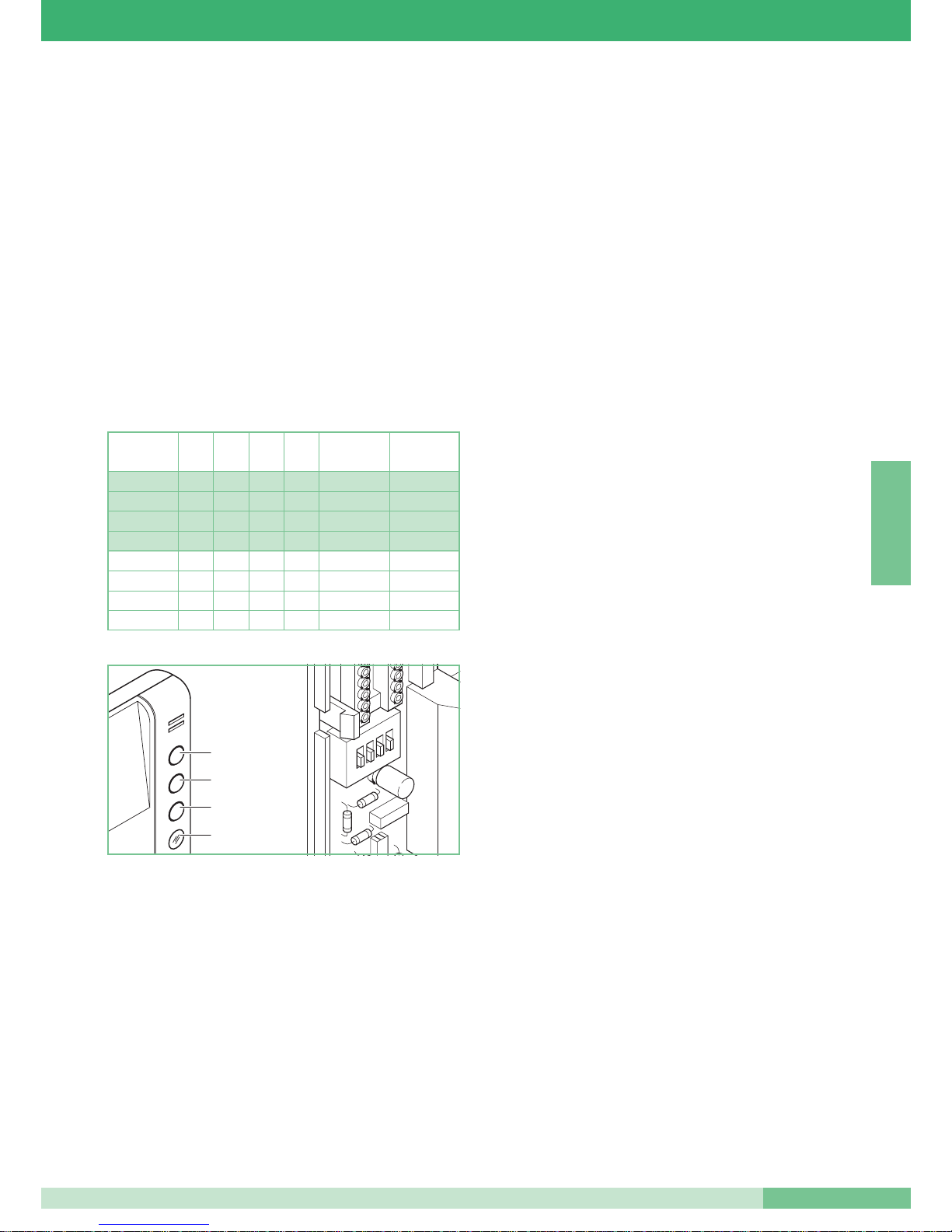
Table 1
S2
1
2
3
4
Signalling
LED
Door-opening
pushbutton
Pushbutton 2
Pushbutton 3
Corrispondence
with BRAVO KIT
Config. 0
DIP 1 DIP 2 DIP 3 DIP 4 Pushbutton 2 Pushbutton 3
Config. 1
Config. 2
Config. 3
0
0
1
0
0
1
1
1
1
0
0
1
0
0
1
1
0
1
1
1
0
0
0
1
0
0
0
0
0
0
0
0
1256 Relay
1256 Relay
1256 Relay
Single-Family
Porter Switchboard
Porter Switchboard
1256 Relay
Porter Switchboard
Privacy
Single-Family
Two-Family
Two-Family
Privacy
Doctor
Doctor
1256 Relay
Page 6
GROUP S.P.A.
FT SB2 09
6
FRANÇAIS
Combiné parlophonique Art. 2410W/2B
Combiné de la série Okay, dimensions 85x223x65 mm.
Le combiné est doté d’un bouton ouvre-porte, d’une led de signalisation et de
deux boutons dont les fonctions sont programmables selon l’installation dans
laquelle il est installé. Il est équipé d’une série de fonctions de l’appel palier
(voir variante A) et de répétition d’appel (voir variante B). Possibilité de monter
jusqu’à trois combinés ayant le même code utilisateur dans la même
installation. Pour programmer le code utilisateur voir “Programmation combiné
Art. 2408W/A, 2428W/A et bride Art. 4714W/2” sur MT/SB2/01 ou FT/SB/07.
Il s’utilise aussi bien sur les installations Simplebus1 que sur les
installations Simplebus2. D’origine, l’article est programmé pour être utilisé
sur les installations Simplebus2.
Pour utiliser le combiné Art. 2410W/2B dans des installations
Simplebus1 et Bravo kit voir note page 2.
L’Art. 2410W/2B permet d’exploiter les fonctions Privacy, Docteur, Relais
1256 et Appel du central de conciergerie sur des installations type
Simplebus1 et Simplebus2 et les Fonctions Privacy, Docteur,
Actionneur,Inter Communication 1 Appartement et 2 Appartements sur des
installations de type Bravo kit. Les programmations du dip-switch S2 pour
attribuer les fonctions à chaque bouton suivent la règle indiquée au Tab. 1.
La fonction
Privacy, si programmée, permet de couper momentanément la
sonnerie du combiné sur appel de la plaque de rue, sur appel du central de
conciergerie.
La fonction Docteur coupe la sonnerie du combiné comme dans la fonction
Privacy et elle permet l’actionnement automatique de l’ouvre-porte sur
appel du combiné venant de la plaque de rue.
Pour valider ou invalider les fonctions Privacy et Docteur, appuyer pendant
2 secondes sur le bouton 3 du combiné; cette validation est indiquée par
l’éclairage de la led de signalisation. Dans le cas de plusieurs utilisateurs
avec le même code utilisateur, programmer la fonction Docteur sur un seul
des appareils validés pour cette fonction. Pour installer l’Art.2410W/2B
dans des installations Simplebus et Bravo kit voir les schémas illustrés à la
sect. A: SB/I1 - SB2/01 - SB/J1.
La fonction relais permet d’activer le relais embarqué sur l’Art. 1256;
programmer cette fonction seulement en présence d’un Art. 1256 en
fonction E (activation sur bouton actionneur).
Pour programmer le relais Art. 1256 avec cette fonction, voir la feuille
technique FT/SB2/02 annexée à l’emballage.
L’appel actionneur s’effectue en appuyant sur le bouton 2 ou sur le bouton
3, selon la programmation du dip-switch S2 (voir Tab.1).
Pour installer l’Art. 2410W/2B dans des installations Simplebus et Bravo kit
voir les schémas illustrés à la sect. A: SB/I1 - SB2/01 - SB/J1.
La fonction appel central de conciergerie permet d’effectuer l’appel à l’Art.
1998 dans les installations. Dans les installations non dotées de l’ Art. 1998,
cette même fonction appel au HP-micro s’utilise pour activer le relais monté
dans l’Art.1256. Pour programmer le relais Art. 1256, voir feuille technique
FT/SB2/02 annexée à l’emballage.
L’appel du central de conciergerie s’effectue en appuyant sur le bouton 2
du combiné, si le dip-switch S2 (voir Tab.1) a été opportunément
programmé.
Pour installer l’Art. 2410W/2B dans des installations Simplebus, voir les
schémas illustrés à la sect. A: SB/I1 - SB2/01 - SB/J1.
La fonction Intercommunication
1 Appartement s’utilise seulement dans
les installations Bravo kit. Elle permet la communication audio entre deux
unités (combiné visiophonique ou parlophonique) programmées sur le
même code utilisateur. La pression sur
P2 ou P3 active l’appel vers les
postes restants de la même unité familiale. En soulevant le récepteur, le
correspondant appelé entre ainsi en communication avec la personne qui
appelle. La communication est coupée lorsqu’il raccroche le récepteur. Un
appel de la plaque de rue est toujours prioritaire.
Dans ce cas, les utilisateurs déjà en communication, entendront dans le
récepteur une tonalité semblable à celle d’appel, si ce dernier leur est
adressé ou, dans le cas contraire une triple tonalité de signalisation.
Pour répondre à l’appel de la plaque de rue, il suffit de soulever le récepteur
d’un quelconque appareil libre ou de raccrocher et de soulever le récepteur
d’un appareil occupé dans une communication interphonique. L’activation
de la communication avec la plaque de rue coupe la communication
interphonique précédemment en cours.
Un appel interphonique n’est pas prioritaire par rapport à une
conversation/appel avec la plaque de rue. Dans ce cas, lors d’une tentative
d’appel interphonique, la led clignotera pendant quelques secondes pour
signaler que le système est occupé. L’appel de l’Appartement s’effectue en
appuyant sur le bouton 2 ou sur le bouton 3, selon le réglage du dip-switch
S2 (voir Tab.1). Pour installer l’Art.2410W/2B dans des installations Bravo kit
voir le schéma SB/J1 à la sect. A.
La fonction intercommunication de
2 Appartements s’utilise seulement
dans les installations Bravo kit. Elle permet la communication audio entre
deux unités (combiné visiophonique ou parlophonique) qui ne sont pas
programmées sur le même code utilisateur. La pression sur le bouton
P3
active l’appel vers les postes de l’autre unité familiale. En soulevant le
récepteur, le correspondant appelé entre ainsi en communication avec la
personne qui appelle. La communication est coupée lorsqu’il raccroche le
récepteur. Un appel de la plaque de rue est toujours prioritaire par rapport
à une communication interphonique. Dans ce cas, les utilisateurs déjà en
communication, entendront dans le récepteur une tonalité semblable à celle
d’appel, si ce dernier leur est adressé ou, dans le cas contraire, une triple
tonalité de signalisation. Pour répondre à l’appel de la plaque de rue, il suffit
de soulever le récepteur d’un quelconque appareil libre ou de raccrocher et
de soulever le récepteur d’un appareil occupé dans la communication
interphonique.
L’activation de la communication avec la plaque de rue coupe la
communication précédemment en cours.
Un appel interphonique n’est pas prioritaire par rapport à une
conversation/appel avec la plaque de rue. Dans ce cas, lors d’une tentative
d’appel interphonique, la led clignotera pendant quelques secondes pour
signaler que le système est occupé.
L’appel interphonique 2 Appartements s’effectue en appuyant sur le bouton
2 ou sur le bouton 3, selon le réglage du dip-switch S2 (voir Tab.1). Pour
installer l’Art.2410W/2B dans des installations Bravo kit voir le schéma
SB/J1 à la sect. A.
Tab. 1
S2
1
2
3
4
Bouton
ouvre-porte
Bouton 2
Bouton 3
Led de
signalisation
Correspondance
avec BRAVO KIT
Config. 0
DIP 1 DIP 2 DIP 3 DIP 4 Bouton 2 Bouton 3
Config. 1
Config. 2
Config. 3
0
0
1
0
0
1
1
1
1
0
0
1
0
0
1
1
0
1
1
1
0
0
0
1
0
0
0
0
0
0
0
0
Art. 1256
Art. 1256
Art. 1256
1 Appart.
Art. 1998
Art. 1998
Art. 1256
Art. 1998
Privacy
1 Appart.
2 Appart.
2 Appart.
Privacy
Docteur
Docteur
1256 Relay
Page 7
FT SB2 09
7
FT SB2 09
NEDERLANDS
Deurtelefoon Art. 2410W/2B
Okay serie deurtelefoon – afmetingen: 85x223x65mm.
De deurtelefoon is uitgevoerd met een deuropener knop, een signaal-LED
en twee drukknoppen waarbij de functies, afhankelijk van het systeem,
ingesteld kunnen worden. Standaard is het toestel voorzien van een ingang
voor een etagebel (zie variant A) en een uitgang voor een extra bel (zie
variant B). Er kunnen maximaal 3 toestellen met dezelfde gebruikerscode
worden ingesteld. Om de gebruikerscode in te stellen verwijzen wij naar
“Programmering van de deurtelefoon Art.2408W/A, 2428W/A en grondplaat
Art. 4714W/2” in de handleiding MT/SB2/01 of FT/SB/07.
Het toestel is zowel voor Simplebus1 als Simplebus2 systemen te
gebruiken. Het toestel is standaard ingesteld voor Simplebus2 systemen.
Om de deurtelefoon Art. 2410W/2B te gebruiken in Simplebus1 en
Bravo kit systemen, verwijzen wij naar de opmerking op pagina 2.
Art. 2410W/2B ondersteund de privacy-, dokter- 1256 relais- en
portieroproep- functies in het Simplebus1 en Simplebus2 systeem en voor
de Bravo kit systemen de privacy-, Dokter-, 1256 relais-, intercom- functies
voor zowel de enkelvoudige als de tweevoudige kits.
De instellingen van de S2 dipswitch bepaald de functie van de
drukknoppen, zoals is aangegeven in tabel 1.
De
Privacy drukknop, wanneer ingeschakeld, kan worden gebruikt om de
bel vanaf het entreepaneel, de etagebel of de portiercentrale.
Naast het uitschakelen van de bel, zoals bij de privacy functie, wordt bij de
dokterfunctie tegelijkertijd de deur automatisch geopend bij een oproep
vanaf het entreepaneel.
Door
2 seconden op drukknop 3 te drukken wordt de Privacy en Dokter
functie geactiveerd. De inschakeling van de functie wordt bevestigd door
het oplichten van de LED. Als er meerdere toestellen dezelfde
gebruikerscode zijn, stel deze functie dan op slechts één toestel in.
Voor het installeren van Art. 2410W/2B in Simplebus en Bravo kit
systemen, zie de schema’s in sect. A: SB/I1 – SB2/01 – SB/J1.
Met de
1256 relais functie kan het relais van Art. 1256 worden
aangestuurd. Stel deze functie alleen in als er een relais Art. 1256 met
functie E(activering door toestelknop) gemonteerd is.
Voor het instellen van relais Art. 1256, verwijzen wij naar de daarbij
meegeleverde handleiding FT/SB2/02.
Het relais Art. 1256 wordt geactiveerd door drukknop 1 of drukknop 2,
afhankelijk van de instelling van de dipswitch
(zie tabel1). Voor het installeren van Art. 2410W/2B in Simplebus en Bravo
kit systemen, zie de schema’s in sect. A: SB/I1 - SB2/01 - SB/J1.
Met de portier oproepfunctie kan de portiercentrale Art. 1998 worden
opgeroepen. Als een systeem niet is uitgevoerd met een portiercentrale,
kan deze drukknop worden gebruikt voor de activering van relais Art.1256.
Om het relais Art. 1256 in te stellen voor deze functie, verwijzen wij naar de
technische handleiding FT/SB2/02 welke meegeleverd wordt met dit relais.
De oproep van de portiercentrale wordt uitgevoerd door drukknop 2 in te
drukken, mits de Dipswitch S2 voor deze functie is ingesteld (zie tabel 1).
Voor het installeren van Art. 2410W/2B in Simplebus systemen, zie de
schema’s in sect. A: SB/I1 - SB2/01 - SB/J1.
De
enkelvoudige intercom functie kan alleen worden gebruikt bij Bravo kit
systemen. Hiermee zijn er interne oproepen en gesprekken mogelijk tussen
toestellen (audio of video) met dezelfde gebruikerscode. Door P2 of P3 in
te drukken worden de andere toestellen met dezelfde gebruikerscode
opgeroepen. Als de hoorn wordt opgenomen kan er worden
gecommuniceerd met degene die het toestel opneemt. De communicatie
wordt beëindigd door de hoorn op te hangen.
Een interne oproep krijgt geen voorrang op een oproep van, of een gesprek
met het entreepaneel. Als er toch wordt geprobeerd een interne oproep te
plaatsen wordt de bezet status aangegeven door de LED, die enkele
seconden zal knipperen.
De enkelvoudige intercom oproep wordt uitgevoerd door
P2 of P3,
afhankelijk van de instellingen van instellingen van de dipswitchen S2 (zie
tabel 1). Voor het installeren van toestel Art. 2410W/2B in Bravo kit
systemen, zie schema SB/J1 in sect. A.
De
Tweevoudige intercom functie kan alleen in de Bravo kit systemen
worden gebruikt: het is mogelijk te communiceren met een toestel (audio of
video) met een andere gebruikerscode. Als drukknop P3 wordt ingedrukt,
vind er een oproep plaats naar de toestellen met de andere gebruikerscode.
Als de hoorn wordt opgenomen kan er worden gecommuniceerd met
degene die het toestel opneemt. De communicatie wordt beëindigd door de
hoorn op te hangen.
Een oproep vanaf het entreepaneel heeft altijd voorrang op de interne
gesprekken.
Als er wordt aangebeld en er is een gesprek gaande met de toestellen
onderling, klinkt de beltoon in de hoorn bij degene waar wordt aangebeld.
De andere gebruiker hoort een drievoudige toon in de hoorn.
Om de oproep van het entreepaneel te beantwoorden kan een vrij toestel
worden opgenomen, of hang de hoorn op en neem deze weer op van een
toestel dat intern in gesprek was. Als de communicatie met het
entreepaneel wordt gestart, wordt de interne verbinding verbroken.
Een interne oproep krijgt geen voorrang op een oproep van, of een gesprek
met het entreepaneel. Als er toch wordt geprobeerd een interne oproep te
plaatsen wordt de bezet status aangegeven door de LED, die enkele
seconden zal knipperen.
De tweevoudige intercom oproep wordt uitgevoerd door op drukknop P3 te
drukken als de S2 dipswitchen juist zijn ingesteld (zie tabel 1).
Voor het installeren van toestel Art. 2410W/2B in Bravo kit systemen, zie
schema SB/J1 in sect. A.
Tab. 1
S2
1
2
3
4
Deuropener
drukknop
Drukknop 2
Drukknop 3
Signaal LED
Correspondeerd
met BRAVO KIT
Config. 0
DIP 1 DIP 2 DIP 3 DIP 4 Drukknop 2 Drukknop 3
Config. 1
Config. 2
Config. 3
0
0
1
0
0
1
1
1
1
0
0
1
0
0
1
1
0
1
1
1
0
0
0
1
0
0
0
0
0
0
0
0
1256 relais
1256 relais
1256 relais
enkelvoudig
Portiercentrale
Portiercentrale
1256 relais
Portiercentrale
Privacy
enkelvoudig
tweevoudig
tweevoudig
Privacy
Dokter
Dokter
1256 relais
Page 8
GROUP S.P.A.
FT SB2 09
8
DEUTSCH
Innenstelle Art. 2410W/2B
Innenstelle der Serie Okay mit den Abmessungen 85x223x65 mm.
Die Innenstelle besitzt außerdem eine Türöffnertaste, eine Anzeige-Led und
zwei Tasten, deren Funktionen entsprechend der Anlage, in der sie
verwendet werden eingestellt werden können. Serienmäßig mit der
Ruffunktion von der Etage aus (siehe Variante A) und mit der
Rufwiederholung (siehe Variante B) ausgestattet. Es ist möglich bis zu 3
Innenstellen mit dem selben Anwendercode in der selben Anlage einzufügen.
Zur Einstellung des Anwendercodes siehe « Programmierung der
Innenstelle Art. 2408W/A, 2428W/A und Bügel Art. 4714W/2 » auf
MT/SB2/01 oder FT/SB/07. Es kann sowohl bei Simplebus1 Anlagen als
auch bei Simplebus2 Anlagen verwendet werden. Der Artikel ist werksseitig
für die Verwendung in Simplebus2 Anlagen eingestellt.
Siehe Hinweis auf Seite 2 für die Verwendung der Innenstelle Art.
2410W/2B in Simplebus1 und Bravo kit Anlagen.
Der Art. 2410W/2B ermöglicht bei Anlagen Typ Simplebus1 und
Simplebus2 die Verwendung der Funktionen Privacy, Doktor, Aktivierung
und Ruf Zentrale, sowie bei Anlagen Typ Bravo kit der Funktionen Privacy,
Doktor, Aktivierung und Interkommunikation Ein- und Zweifamilienhäuser.
Die Regeln für die Einstellung der Dip-Schalter S2 für die Zuordnung der
Tasten sind in Tab. 1 angeführt.
Die Funktion
Privacy ermöglicht, falls eingestellt, die vorübergehende
Abschaltung des Ruftons der Gegensprechanlage von der Außenstelle, von
der Portierzentrale.
Die Funktion Doktor ermöglicht zusätzlich zum Ausschalten der
Innenstelle, wie bei der Funktion Privacy, die automatische Betätigung des
Türöffners bei Anruf des Teilnehmercodes von der Außenstelle.
Die Freigabe oder Sperrung der Privacy- und der Doktorfunktionen erfolgt
durch
2 Sekunden langes Drücken der Taste 3 der Innenstelle Die
Aktivierung wird zusätzlich durch das Aufleuchten der Anzeige-Led
signalisiert. Falls mehrere Teilnehmer den gleichen Teilnehmercode
besitzen muss die Funktion Doktor nur bei einem der mit dieser Funktion
aktivierten Geräte eingestellt werden. Für den Einbau des Art. 2410W/2B in
Anlagen Typ Simplebus und Bravo kit siehe Schemata Abschn. A: SB/I1 SB2/01 - SB/J1.
Die Ruffunktion
Aktivierung ermöglicht die Aktivierung des Relais im Art.
1256. Diese Funktion darf nur eingestellt werden, wenn ein Art. 1256 mit
eingestellter Funktion E (Aktivierung bei Taster) verwendet wird.
Siehe beiliegendes Technik-Merkblatt FT/SB2/02 für die Einstellung des
Moduls Aktivierungsrelais Art. 1256, damit sich dieses auf Befehl des
Tasters einschaltet.
Der Tasteranruf erfolgt durch Betätigen der Taste 2 oder Taste 3, je nach
Einstellung. Für den Einbau des Art. 2410W/2B in Anlagen Typ Simplebus
und Bravo kit siehe Schemata Abschn. A: SB/I1 - SB2/01 - SB/J1.
Die Funktion Ruf
Zentrale ermöglicht bei Anlagen mit Portierzentrale Art.
1998 den Anruf derselben. Bei Anlagen ohne Zentrale Art. 1998 kann die
gleiche Funktion verwendet werden, um das Relais des Art. 1256 zu
aktivieren. Siehe beiliegendes Technik-Merkblatt FT/SB2/02 für die
Einstellung des Modul Aktivierungsrelais Art. 1256, damit sich dieses auf
Befehl des Anrufs der Zentrale einschaltet.
Der Anruf der Zentrale erfolgt durch Betätigen der Taste 2 der Innenstelle,
sofern der Dip-Schalter S2 korrekt eingestellt ist (siehe Tab. 1).
Für den Einbau des Art. 2410W/2B in Anlagen Typ Simplebus siehe
Schemata Abschn. A: SB/I1 - SB2/01 - SB/J1.
Die Interkommunikationsfunktion für
Einfamilienhäuser kann nur in Bravo
kit Anlagen verwendet werden. Diese ermöglicht die Audiokommunikation
zwischen zwei Einheiten (Innenstellen und Video- Innenstellen), die auf den
gleichen Teilnehmercode eingestellt sind. Das Betätigen von
P2 oder P3
aktiviert den Ruf zu den verbleibenden Stellen der gleichen Wohneinheit.
Der Rufempfänger muss den Hörer abnehmen, um so mit dem Anrufer zu
kommunizieren. Durch erneutes Auflegen des Hörers wird die
Kommunikation beendet. Ein Anruf von der Außenstelle hat immer Vorrang
über eine interne Kommunikation. In diesem Fall vernehmen die Benutzer,
die sich bereits in einer Konversation befinden, einen Ton, der dem Rufton
ähnlich ist, wenn der Ruf an sie gerichtet ist, andernfalls einen dreifachen
Signalton. Um auf den Ruf von einer Außenstation zu antworten, genügt es,
den Hörer von irgendeinem freien Apparat abzunehmen oder den Hörer
von einem Apparat, der zur Interkommunikation benutzt wird, aufzulegen
und wieder abzunehmen. Die Aktivierung der Kommunikation mit einer
Außenstation unterbricht die vorher laufende Interkommunikation.
Ein Anruf zur Interkommunikation hat keine Priorität vor einer Konversation
mit der Außenstation oder vor einem Anruf von dort. In diesem Fall blinkt
die LED während des Versuchs eines interkommunizierenden Anrufs einige
Sekunden lang, um zu signalisieren, dass das System belegt ist.
Die Interkommunikation in Einfamilienanlagen erfolgt durch Betätigen der
Taste 2 oder Taste 3, je nach Einstellung des Dip-Schalters S2 (siehe Tab.
1). Für den Einbau des Art. 2410W/2B in Anlagen Typ Bravo kit siehe
Schema SB/J1 im Abschn. A.
Die Interkommunikation in
Zweifamilienhäusern kann nur in Bravo kit
Anlagen verwendet werden: Diese ermöglicht die Audiokommunikation
zwischen zwei Einheiten (Innenstellen und Video- Innenstellen), die nicht
auf den gleichen Teilnehmercode eingestellt sind. Das Betätigen der Taste
P3 aktiviert den Ruf zu den Stellen der anderen Wohneinheit. Wenn der
Empfänger des Anrufs den Hörer abnimmt, tritt er mit dem Anrufer in
Verbindung. Durch erneutes Auflegen des Hörers wird die Kommunikation
beendet.
Ein Ruf von einer Außenstation hat in jeden Fall Priorität vor einer
Interkommunikation. In diesem Fall vernehmen die Benutzer, die sich
bereits in einer Konversation befinden, einen Ton, der dem Rufton ähnlich
ist, wenn der Ruf an sie gerichtet ist, andernfalls einen dreifachen
Signalton. Um auf den Ruf von einer Außenstation zu antworten, genügt es,
den Hörer von irgendeinem freien Apparat abzunehmen oder den Hörer
von einem Apparat, der zur Interkommunikation benutzt wird, aufzulegen
und wieder abzunehmen. Die Aktivierung der Kommunikation mit einer
Außenstation unterbricht die vorher laufende Interkommunikation.
Ein Anruf zur Interkommunikation hat keine Priorität vor einer Konversation
mit der Außenstation oder vor einem Anruf von dort. In diesem Fall blinkt
die LED während des Versuchs eines interkommunizierenden Anrufs einige
Sekunden lang, um zu signalisieren, dass das System belegt ist.
Die Interkommunikation in Zweifamilienanlagen erfolgt durch Betätigen der
Taste 3, sofern der Dip-Schalter S2 korrekt eingestellt ist (siehe Tab. 1).
Für den Einbau des Art. 2410W/2B in Anlagen Typ Bravo kit siehe Schema
SB/J1 im Abschn. A.
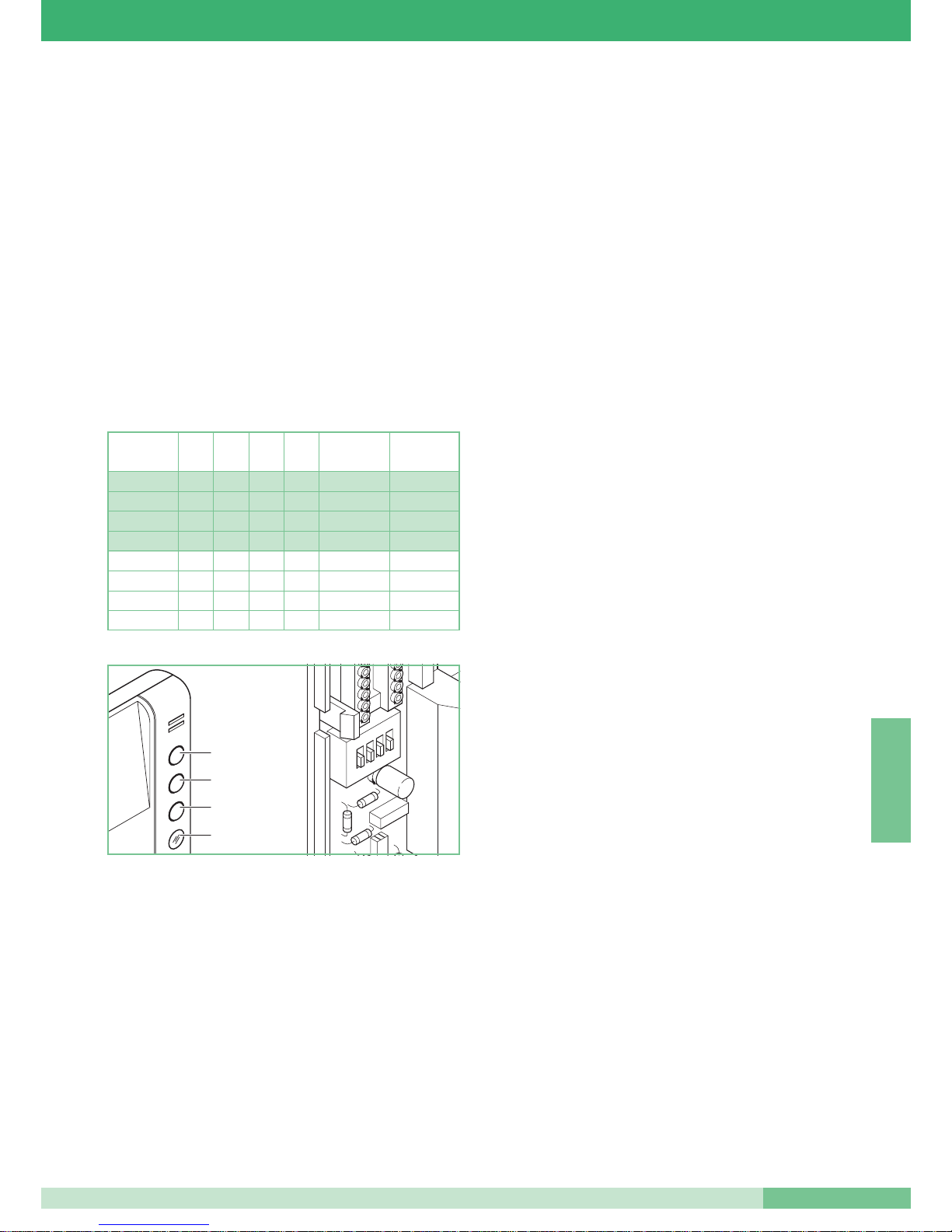
Tab. 1
S2
1
2
3
4
Türöffnertaste
Taste 2
Taste 3
Anzeige-Led
Übereinstimmung
mit BRAVO KIT
KONFIG. 0
DIP 1 DIP 2 DIP 3 DIP 4 Taste 2 Taste 3
KONFIG. 1
KONFIG. 2
KONFIG. 3
0
0
1
0
0
1
1
1
1
0
0
1
0
0
1
1
0
1
1
1
0
0
0
1
0
0
0
0
0
0
0
0
Aktivierungsrelais
Aktivierungsrelais
Aktivierungsrelais
Einfamilienhaus
Zentrale
Zentrale
Aktivierungsrelais
Zentrale
Privacy
Einfamilienhaus
Zweifamilienhaus
Zweifamilienhaus
Privacy
Doktor
Doktor
Aktivierungsrelais
Page 9
FT SB2 09
9
FT SB2 09
PORTUGUÊS
Telefone Art. 2410W/2B
Telefone da série Okay com dimensões 85x223x65 mm.
O telefone é fornecido com, para além do botão de abertura porta, um LED
de sinalização e dois botões cujas funções são configuráveis de acordo
com a instalação onde for instalado. De série é equipado com a função
Chamada pelo andar (ver variação A) e de Repetidor de chamada (ver
variação B). É possível inserir até três telefone com o mesmo código de
utente na mesma instalação.
Para configurar o código usuário ver “Programação do telefone Art.
2408W/A, 2428W/A e suporte Art. 4714W/2” em MT/SB2/01 ou FT/SB/07.
Pode ser usado em instalações Simplebus1 e em instalações Simplebus2.
O artigo, de fábrica, é configurado para ser usado em instalações
Simplebus2.
Para usar o telefone Art. 2410W/2B em instalações
Simplebus1 e Bravo kit ver nota pág. 2.
O art. 2410W/2B permite dispôr das funções Privacidade, Doutor,
Actuador e Chamada na Central em instalações tipo Simplebus1 e
Simplebus2 e as funções Privacidade, Doutor, Actuador, intercomunicante
Monofamiliar e Bifamiliar sobre instalações tipo Bravo kit.
As configurações do Dip switches S2 para atribuir as funções a cada botão
seguem a regra de Tab. 1.
A função
Privacidade, se configurada, permite desativar temporàriamente
o som do telefone para chamada de posto externo, com chamada pela
central de portaria.
A função Doutor além de desativar o som do telefone como na função
Privacidade, permite o acionamento automático do abridor de porta com o
código de usuário do telefone pelo posto externo.
A habilitação ou a desabilitação das funções Privacidade e Doutor é
efectuada carregando
durante 2 segundos o botão 3 do telefone. Além
disso, a habilitação é indicada pelo acendimento do LED de sinalização. No
caso de mais usuários com o mesmo código configurarem a função
Doutor em um só dos aparelhos habilitados para esta função. Para a
introdução do Art.2410W/2B em instalações Simplebus e Bravo kit ver
esquemas na seç.A: SB/I1 - SB2/01 - SB/J1.
A função denominada
Actuador permite activar o relé contido no Art.
1256; configurar esta função somente se houver um Art. 1256 na função E
( activação no botão Actuador.).
Para configurar o módulo de relé actuador Art. 1256 de maneira que se ative
no comando actuador ver folheto técnico FT/SB2/02 anexo à embalagem.
A chamada actuador é efetuada pressionando o botão 2 ou o botão 3 da
configuração, Para a introdução do Art. 2410W/2B em instalações
Simplebus e Bravo kit ver esquemas na seç. A: SB/I1 - SB2/01 - SB/J1.
A função denominada
Central permite efetuar a chamada na central de
portaria Art. 1998 nas instalações que possuem a central. Nas instalações
que não possuem a central Art. 1998 a mesma função chamada na central
pode ser usada para activar o relé contido no Art.1256. Para configurar o
módulo relé actuador Art. 1256 de maneira que se ative no comando
chamada central, ver folheto técnico FT/SB2/02 anexo à embalagem.
A chamada central é efectuada pressionando o botão 2 do telefone se
apropriadamente configurado o Dip Swtches S2 (ver Tab. 1)
Para a introdução do Art. 2410W/2B em instalações Simplebus ver
esquemas na seç. A: SB/I1 - SB2/01 - SB/J1.
A função intercomunicante
Monofamiliar pode ser usada somente nas
instalações Bravo kit. A mesma permite a comunicação áudio entre duas
unidades (vídeo porteiro ou telefone ) configuradas no mesmo código
usuário. Carregando o Botão (
P2 ou P3) activa a chamada para os outros
postos restantes da mesma unidade familiar. O receptor da chamada
levantando o punho entra assim em comunicação com quem chama.
Colocando o punho no gancho a comunicação termina. Uma chamada do
posto externo é de qualquer modo sempre prioritária em relação a uma
comunicação intercomunicante.
Neste caso os utentes que estão comunicando ouvirão no punho um tom
semelhante àquele de chamada se a mesma é endereçada aos mesmos
ou um tom triplo de sinalização em caso contrário.
Para responder à chamada do posto externo é suficiente levantar o punho
de qualquer aparelho livre ou colocar no gancho e levantar o punho de um
aparelho ocupado na comunicação intercomunicante. A activação da
comunicação com o posto externo interrompe a conversa intercomunicante
anteriormente em curso.
Uma chamada intercomunicante não é prioritária em relação a uma
conversa/chamada com o posto externo. Neste caso, durante uma
tentativa de chamada intercomunicante, o LED lampejará durante alguns
segundos para sinalizar que o sistema está ocupado.
A chamada intercomunicante Monofamiliar é efetuada pressionando o
botão 2 ou o botão 3 de acordo com a configuração do Dip switches S2 (ver
Tab. 1). Para a introdução do Art. 2410W/2B em instalações Bravo kit ver
esquema SB/J1 na seç. A.
A função intercomunicante
Bifamiliar pode ser usada somente nas
instalações Bravo kit: a mesma permite a comunicação áudio entre duas
unidades (vídeo porteiro ou telefone) que não são configuradas no mesmo
código usuário. Carregando o Botão P3 activa a chamada para os postos
da outra unidade familiar. O receptor da chamada levantando o punho
entra assim em comunicação com quem chama. Colocando o punho no
gancho a comunicação termina.
Uma chamada do posto externo é de qualquer modo sempre prioritária em
relação a uma comunicação intercomunicante. Neste caso os utentes que
já estão comunicando ouvirão no punho um tom semelhante àquele de
chamada se a mesma é endereçada aos mesmos ou um tom triplo de
sinalização em caso contrário. Para responder à chamada do posto externo
é suficiente levantar o punho de qualquer aparelho livre ou colocar no
gancho e levantar o punho de um aparelho ocupado na comunicação
intercomunicante.
A activação da comunicação com o posto externo interrompe a conversa
intercomunicante anteriormente em curso. Uma chamada intercomunicante
não é prioritária em relação a uma conversa/chamada com o posto externo.
Neste caso, durante uma tentativa de chamada intercomunicante, o LED
lampejará durante alguns segundos para sinalizar que o sistema está ocupado.
A chamada intercomunicante Bifamiliar é efetuada pressionando o botão 3
se apropriadamente configurado o Dip Switches S2 (ver Tab. 1)
Para a introdução do Art.2410W/2B em instalações Bravo kit ver esquema
SB/J1 na seç. A.
S2
1
2
3
4
Tab. 1
Botão 3
Botão 2
Botão de
abertura porta
Led de
sinalização
Correspondência
com BRAVO KIT
Config. 0
DIP 1 DIP 2 DIP 3 DIP 4 Botão 2 Botão 3
Config. 1
Config. 2
Config. 3
0
0
1
0
0
1
1
1
1
0
0
1
0
0
1
1
0
1
1
1
0
0
0
1
0
0
0
0
0
0
0
0
Actuador
Actuador
Actuador
Monofamiliar
Central
Central
Actuador
Central
Privacidade
Monofamiliar
Bifamiliar
Bifamiliar
Privacidade
Doutor
Doutor
Actuador
Page 10
GROUP S.P.A.
FT SB2 09
10
ESPAÑOL
el mando actuador véase hoja técnica FT/SB2/02 anexa a la confección.
La llamada actuador se efectúa presionando el pulsador 2 o el pulsador 3 a
de la instalación . Para la introducción del Art. 2410W/2B en instalaciones
Simplebus y Bravo kit véase esquemas en la secc A. SB/I1 - SB2/01 - SB/J1.
La función de llamada
Central permite efectuar la llamada a la centra de
portería Art. 1998 en las instalaciones provistas de central. En las
instalaciones sin central Art. 1998 la misma función de llamada a la central se
puede utilizar para activar el relé a bordo del Art. 1256. Para programar el
módulo relé actuador Art. 1256 de manera que se active a la orden de llamada
de central véase hoja técnica FT/SB2/02 anexa a la confección.
La llamada central se efectúa presionando el pulsador 2 del telefonillo si se ha
programado oportunamente el Dip switches S2 (véase Tabla 1).
Para la introducción del Art.2410W/2B en instalaciones Simplebus véase
esquemas en la secc.A: SB/I1 - SB2/01 - SB/J1.
La función intercomunicante
Unifamiliar se puede utilizar solo en las
instalaciones Bravo kit. Esta permite la comunicación audio entre dos
unidades (vídeo portero o telefonillo) programadas en el mismo código
usuario. La presión del (
P2 o P3) activa la llamada hacia los demás puestos
de la misma unidad familiar. El receptor de la llamada levantando el auricular
entra así en comunicación con la persona que llama. Colgando el auricular la
comunicación finaliza. Una llamada desde la unidad externa siempre tiene
prioridad con respecto a una comunicación intercomunicante.
En este caso los usuarios que se encuentran en conversación sentirán en
el auricular un tono parecido al de llamada si esta última está dirigida a
ellos o un triple tono de señalación en caso contrario.
Para responder a la llamada desde la unidad externa basta levantar el
auricular desde cualquier aparato libre o colgar y levantar el auricular desde
un aparato con una comunicación intercomunicante. La activación de la
comunicación con la unidad externa interrumpe la conversación
intercomunicante precedentemente en curso.
Una llamada intercomunicante no tiene prioridad con respecto a una
comunicación/llamada con la unidad externa. En este caso, durante un
tentativo de llamada intercomunicante, el LED parpadeará durante algunos
segundos para señalar que el sistema está ocupado.
La llamada intercomunicante Unifamiliar se efectúa presionando el
pulsador 2 o el pulsador 3 según la programación del Dip switches S2
(véase Tabla 1). Para la introducción del Art.2410W/2B en instalaciones
Bravo kit véase esquema SB/J1 en la secc.A.
La función intercomunicante
Unifamiliar se puede utilizar solo en las
instalaciones Bravo kit. esta permite la comunicación audio entre dos
unidades (Vídeo portero o telefonillo) que no están programadas en el mismo
código usuario. La presión del Pulsador
P3 activa la llamada hacia los demás
puestos de la otra unidad familiar. El receptor de la llamada levantando el
auricular entra así en comunicación con la persona que llama. Colgando el
auricular la comunicación finaliza.
Una llamada desde la unidad externa siempre tiene prioridad con respecto a
una comunicación intercomunicante. En este caso los usuarios que se
encuentran en conversación sentirán en el auricular un tono parecido al de
llamada si esta última está dirigida a ellos o un triple tono de señalación en
caso contrario. Para responder a la llamada desde la unidad externa basta
levantar el auricular desde cualquier aparato libre o colgar y levantar el
auricular desde un aparato con una comunicación intercomunicante.
La activación de la comunicación con la unidad externa interrumpe la
conversación intercomunicante precedentemente en curso.
Una llamada intercomunicante no tiene prioridad con respecto a una
comunicación/llamada con la unidad externa. En este caso, durante un
tentativo de llamada intercomunicante, el LED parpadeará durante algunos
segundos para señalar que el sistema está ocupado.
La llamada intercomunicante Bifamiliar se efectúa presionando el pulsador
3 del telefonillo si se ha programado oportunamente el Dip switches S2
(véase Tabla 1).
Para la introducción del Art.2410W/2B en instalaciones Bravo kit véase
esquema SB/J1 en la secc.A.
Tab. 1
S2
1
2
3
4
Pulsador 3
Pulsador 2
Pulsador
abre puerta
Led de
señalización
Telefonillo Art. 2410W/2B
Telefonillo de la serie Okay de dimensiones 85x223x65 mm.
El telefonillo se suministra con el pulsador abre puerta, un LED para la
señalización y dos pulsadores cuyas funciones se programan según la
instalación en la que se introduce. Equipado de serie de función de llamada
del piso (véase variante A) y de Repetición de llamada (véase variante B).
Es posible introducir hasta tres telefonillos con el mismo código de usuario
en la misma instalación.
Para programación del código usuario véase “Programación telefonillo Art.
2408W/A, 2428W/A y placa soporte Art.4714W/2” en MT/SB2/01 o FT/SB/07.
Se puede utilizar tanto en instalaciones Simplebus1 como en instalaciones
Simplebus2. El artículo, de fábrica, se programa para poder utilizarse en
instalaciones Simplebus2.
Para utilizar el telefonillo Art. 2410W/2B en
instalaciones Simplebus1 y Bravo kit véase nota pág. 2.
El Art. 2410W/2B permite aprovechar las funciones de servicio Privado,
Doctor, Actuador y Llamada a la Central en instalaciones tipo Simplebus1
y Simplebus2 y las funciones de servicio Privado, Doctor, Actuador,
intercomunicante Unifamiliar y Bifamiliar en instalaciones tipo Bravo kit.
Las programaciones del Dip switches S2 para asignar las funciones a cada
pulsador siguen la regla de la Tabla 1.
La Función de
Servicio Privado, si estuviera programada, permite desactivar
momentáneamente el timbre del telefonillo tanto en la llamada desde la unidad
externa como en la llamada desde la central de portería.
La función Doctor además de desactivar el timbre del telefonillo como en la
función de servicio Privado, permite el accionamiento automático del abre
puerta en llamada al código del usuario del telefonillo mediante la unidad
externa.
La habilitación o deshabilitación de las funciones de servicio Privado y Doctor
se realizan presionando durante
2 segundos el pulsador 3 del Telefonillo; la
habilitación además está indicada por el encendido del LED de señalización.
En el caso de más usuarios con el mismo código de usuario programar la
función Doctor en uno de los aparatos habilitados para esta función. Para la
introducción del Art.2410W/2B en instalaciones Simplebus y Bravo kit véase
esquemas en la secc.A: SB/I1 - SB2/01 - SB/J1.
La función de llamada
Actuador permite activar el relé a bordo del Art. 1256,
programar esta función solo si estuviera presente un Art. 1256 en función E
(activación en el pulsador actuador).
Para programar el módulo relé actuador Art. 1256 de manera que se active en
Correspondencia
con BRAVO KIT
Config. 0
DIP 1 DIP 2 DIP 3 DIP 4 Pulsador 2 Pulsador 3
Config. 1
Config. 2
Config. 3
0
0
1
0
0
1
1
1
1
0
0
1
0
0
1
1
0
1
1
1
0
0
0
1
0
0
0
0
0
0
0
0
Actuador
Actuador
Actuador
Unifamiliar
Central
Central
Actuador
Central
Servicio Privado
Unifamiliar
Bifamiliar
Bifamiliar
Servicio Privado
Doctor
Doctor
Actuador
Page 11
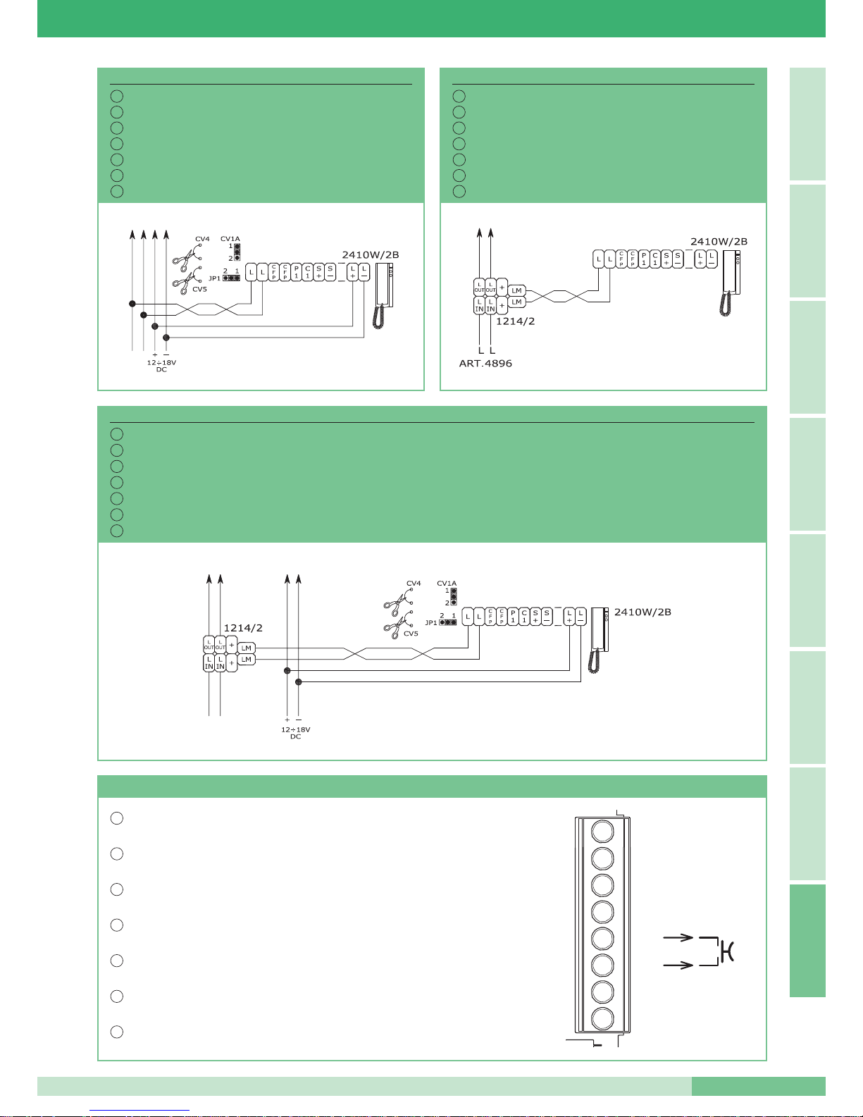
SB/J1
Installazione Art. 2410W/2B in impianti misti Audio/Video tipo Simplebus1 o in impianti Bravo kit.
Installation of Art. 2410W/2B in mixed Audio/Video Simplebus1 type systems or in Bravo kit systems.
Installation Art. 2410W/2B dans des installations mixtes Audio/Vidéo type Simplebus 1 ou dans des installations Bravo kit.
Installatie met 2410W/2B in gemixte audio/video Simplebus1 systemen of Bravo kit systemen.
Installation Art. 2410W/2B in gemischten Audio-/Videoanlagen Typ Simplebus1 oder Bravo kit.
Instalação Art. 2410W/2B em instalações mistas áudio/vídeo tipo Simplebus 1 ou em instalações Bravo kit.
Instalación Art. 2410W/2B en instalaciones mixtas Audio/Vídeo tipo Simplebus1 o en instalaciones Bravo kit.
FT SB2 09
11
FT SB2 09
A
ESPAÑOL
PORTUGUÊS DEUTSCH
NEDERLANDS
FRANÇAIS
ENGLISH ITALIANO
SB/I1
I
GB
F
NL
D
P
E
Installazione Art. 2410W/2B in impianti solo Audio
Installation of Art. 2410W/2B in Audio only systems.
Installation Art. 2410W/2B dans des installations seulement Audio.
Installatie van Art. 2410W/2B in een audio systeem.
Installation Art. 2410W/2B in reinen Audioanlagen.
Instalação Art. 2410W/2B em instalações apenas Áudio.
Instalación Art. 2410W/2B en instalaciones solo Audio.
E
P
D
NL
F
GB
I
SB2/01
Installazione Art. 2410W/2B in impianti misti Audio/Video tipo Simplebus2.
Installation of Art. 2410W/2B in mixed Audio/Video Simplebus2 type systems.
Installation Art. 2410W/2B dans des installations mixtes Audio/Vidéo type Simplebus 2.
Installatie van Art. 2410W/2B in gemixte audio/video Simplebus2 systemen.
Installation Art. 2410W/2B in gemischten Audio-/Videoanlagen Typ Simplebus2.
Instalação Art. 2410W/2B em instalações mistas Áudio/Vídeo tipo Simplebus2.
Instalación Art. 2410W/2B en instalaciones mixtas Audio/Vídeo tipo Simplebus2.
E
P
D
NL
F
GB
I
VARIANTE A - VARIANT A - VARIANTE A - VARIANT A - VARIANTE A - VARIANTE A - VARIANTE A
Utilizzo della chiamata da piano sul citofono Art. 2410W/2B: connettere il pulsante sui morsetti CFP CFP.
I citofoni con il medesimo codice utente suonano contemporaneamente su chiamata da piano.
Use of the floor door call on telephone Art. 2410W/2B: connect the pushbutton to terminals CFP CFP.
The telephones with the same user code ring at the same time on a floor door call.
Utilisation de l’appel palier sur le combiné parlophonique Art. 2410W/2B: connecter le bouton aux bornes
CFP CFP. Les combinés ayant le même code utilisateur retentissent en même temps sur appel palier.
Gebruik van de etagebel op de deurtelefoon art. 2410W/2B: sluit de drukknop aan op CFP CFP. De
deurtelefoons met dezelfde gebruikerscode bellen tegelijkertijd bij een verdiepingsoproep.
Verwendung des Etagenrufens auf der Innenstelle Art. 2410W/2B: Die Taste an die Klemmen CFP CFP
anschließen. Die Innenstellen mit dem selben Anwendercode klingeln gleichzeitig beim Rufen von der Etage aus.
Uso do telefone Art. 2410W/2B em chamadas do patim da escada: conectar o botão nos bornes CFP CFP.
Os telefones com o mesmo código utente tocam simultaneamente em chamada de andar.
Uso de la llamada del piso al telefonillo Art. 2410W/2B: conectar el pulsador en las bornas CFP CFP.
Los telefonillos con el mismo código usuario suenan contemporáneamente en la llamada desde el piso.
I
GB
NL
F
D
P
E
S -
C1
P1
CFP
CFP
L
L
S +
Page 12
FT/SB2/09 - 1
a
edizione 01/2006 - cod. 22590023
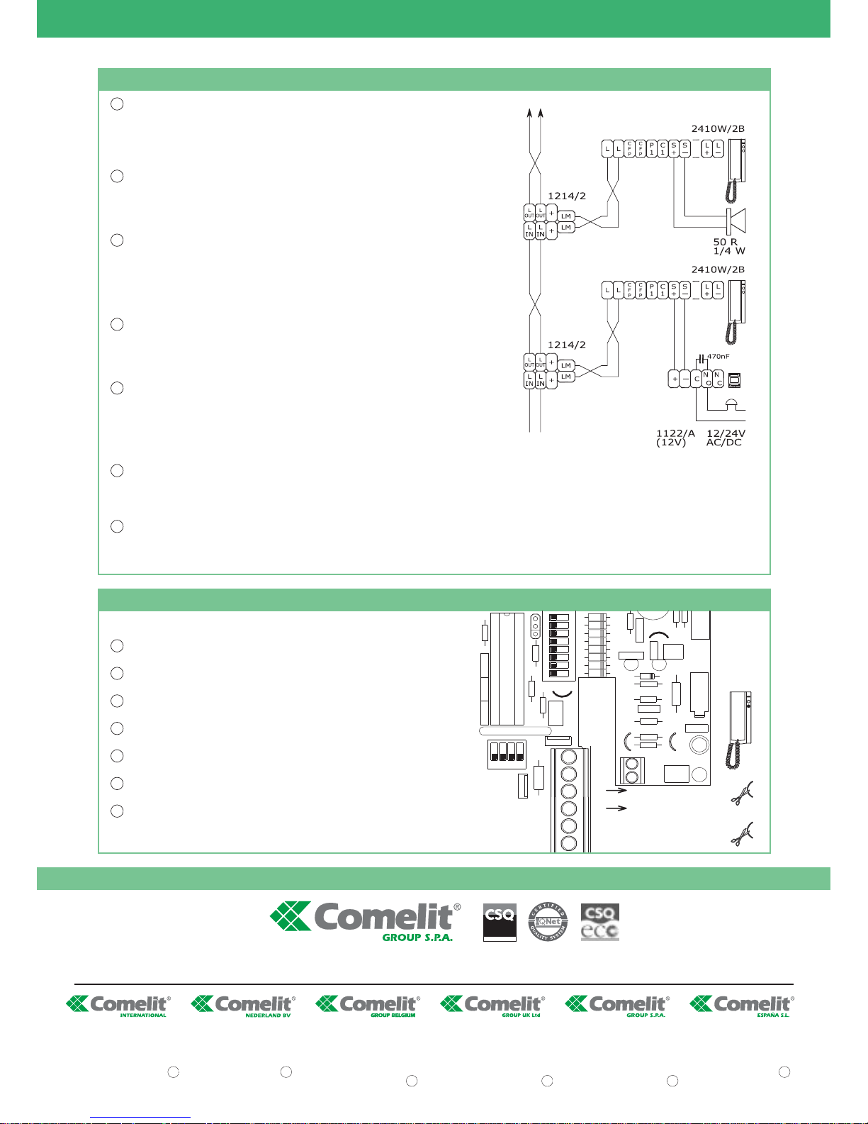
VARIANTE B - VARIANT B - VARIANTE B - VARIANT B - VARIANTE B - VARIANTE B - VARIANTE B
Connessione di dispositivi di ripetizione di chiamata sul citofono 2410W/2B: la somma totale del numero di posti interni con
stesso codice utente e del numero di dispositivi di ripetizione chiamata collegati ai suddetti posti interni non può superare il numero di
4. Connettere un solo dispositivo di ripetizione chiamata per ogni posto interno. La distanza MAX del collegamento tra posto interno
e dispositivo di ripetizione chiamata è di
20 m; utilizzare cavo schermato per il collegamento e non far passare i cavi in prossimità di
carichi induttivi pesanti o cavi di alimentazione (220V / 380V). Impostare l’Art. 1122/A presente nello schema SB2/P1 a fianco per
funzionamento a 12V. Connettere sui contatti C-NO dell’Art. 1122/A solo dispositivi funzionanti in bassa tensione. In caso di
connessione di carichi induttivi si consiglia l’inserimento di una capacità di 470nF in parallelo ai contatti C-NO dell’Art. 1122/A.
Connection of call repetition device on telephone 2410W/2B: the total number of internal units with the same user code summed with
the number of call repetition devices connected to these internal units cannot exceed 4. Connect only one call repetition device for each
internal unit. The MAX connection distance between internal unit and call repetition device is 20 m. Use shielded cable for the connection
and do not run the cables near heavy inductive loads or power supply cables (220V / 380V). Set Art. 1122/A shown in diagram SB2/P1
at the side for operation at 12V. Only connect devices operating with low voltage to the C-NO contacts of Art. 1122/A. In the case of
connection of inductive loads, insertion of a capacity of 470nF in parallel with the C-NO contacts of Art. 1122/A is raccomended.
Connexion de dispositifs de répétition d’appel sur le combiné parlophonique 2410W/2B: la somme du nombre de postes
intérieurs ayant le même code utilisateur et du nombre de dispositifs de répétition d’appel branchés à ces postes intérieurs ne peut
pas être supérieure à 4. Connecter un seul dispositif de répétition d’appel pour chaque poste intérieur. La distance MAX de la
connexion entre le poste intérieur et le dispositif de répétition d’appel est de 20 m; pour la connexion, utiliser un câble blindé et ne pas
faire passer les câbles à proximité de charges inductives lourdes ou de câbles d’alimentation (220V / 380V). Régler l’Art. 1122/A
présent dans le schéma SB2/P1 ci-contre, pour le fonctionnement à 12V. Sur les contacts C-NO de l’Art. 1122/A brancher seulement
les dispositifs fonctionnant à basse tension. En cas de connexion de charges inductives, il est conseillé d’installer une capacité de
470nF en parallèle aux contacts C-NO de l’Art. 1122/A.
Aansluiting van een extra bel op deurtelefoon 2410W/2B: Het maximale aantal toestellen met dezelfde gebruikerscode plus het
aantal extra bellen mag nooit groter zijn dan 4. Sluit maximaal één extra bel aan op een toestel. De MAXIMALE lengte afstand tussen
het toestel en de extra bel is 20 m. Gebruik afgeschermde kabel voor deze aansluiting en zorg ervoor dat deze niet in de buurt ligt van
zware inductieve voedingskabels.(230V/400V). Stel Art. 1122/A in op 12V, zoals aangegeven in schema SB2/P1. Sluit alleen
laagspanningapparatuur aan op de C/NO contacten van Art. 1122/A. Als er een inductieve last wordt aangesloten, adviseren wij een
condensator van 470nF parallel over de C-NO contacten van art. 1122/A aan te sluiten.
Anschluss der Rufwiederholungsvorrichtungen an die Innenstelle 2410W/2B: Die Gesamtanzahl der Innenstellen mit dem gleichen
Teilnehmercode und die Anzahl der Vorrichtungen zur Rufwiederholung die an die genannten Innenstellen angeschlossen werden, darf
nicht mehr als 4 sein. Es darf nur eine Vorrichtung zur Rufwiederholung je Innenstation angeschlossen werden. Die maximale Entfernung
zwischen Innenstation und Vorrichtung zur Rufwiederholung beträgt 20 m; zur Verbindung ist ein geschirmtes Kabel zu verwenden und
die Kabel dürfen nicht in der Nähe von großen induktiven Belastungen oder von Kabeln zur Stromversorgung (220V/380V) verlegt werden.
Den Art. 1122/A einstellen der auf dem nebenstehenden Schema SB2/P1, zum 12V Betrieb verwendet wird. Nur die Vorrichtungen mit
den C-NO Kontakten des Art. 1122/A verbinden, die mit niedriger Spannung funktionieren. Im Falle von Verbindungen mit induktiven
Belastungen empfiehlt sich eine Parallelschaltung mit einer Kapazität von 470 nF parallel zu den C-NO Kontakten des Art. 1122/A.
Conexão de dispositivos de repetição de chamada no telefone 2410W/2B: a soma total do número de postos internos com o mesmo código utente e do número de dispositivos de repetição de chamada ligados aos
postos internos não pode exceder o número de 4. Ligar apenas um dispositivo de repetição de chamada para cada posto interno. A distância MAX da ligação entre posto interno e o dispositivo de repetição de chamada
é de 20 m; usar cabo blindado para a ligação e não fazer os cabos passarem na proximidade de cargas indutivas pesadas ou cabos de alimentação (220V / 380V). Configurar o Art. 1122/A presente no esquema SB2/P1
ao lado para funcionamento a 12V. Conectar nos contatos C-NO do Art. 1122/A somente dispositivos que funcionam com baixa tensão. Em caso de conexão de cargas indutivas aconselha-se a introdução de uma resistência
de 470nF em paralelo aos contactos C-NO do Art. 1122/A.
Conexión de dispositivos de repetición de llamada en el telefonillo 2410W/2B: la suma total del número de las unidades internas con el mismo código de usuario y del número de dispositivos de repetición de llamada
conectados a dichas unidades internas no puede ser más de 4. Conectar un único dispositivo de repetición de llamada para cada unidad interna La distancia MÁX de la conexión entre la unidad interna y dispositivo de
repetición de llamada es de 20 m; utilizar el cable blindado para la conexión y no dejar pasar los cables cerca de las cargas inductivas pesadas o cables de alimentación (220V / 380V). Programar el Art. 1122/A que se
encuentra al lado del esquema SB2/P1 para el funcionamiento a 12V. Conectar en los contactos C-NO del Art. 1122/A solo dispositivos que funcionan a baja tensión. En caso de conexión de cargas inductivas es aconsejable
la conexión de una capacidad de 470nF en paralelo a los contactos C-NO del Art. 1122/A.
I
GB
NL
F
D
P
E
VARIANTE C - VARIANT C - VARIANTE C - VARIANT C - VARIANTE C - VARIANTE C - VARIANTE C
Utilizzo per usi vari del pulsante 2 sul citofono Art. 2410W/2B (normalmente dedicato alla chiamata centralino):
tagliare i cavallotti CV2 e CV3 e connettere il dispositivo sui morsetti P1 C1.
Use for various purposes of pushbutton 2 on telephone Art. 2410W/2B (normally dedicated to the porter
switchboard call): cut jumpers CV2 and CV3 and connect the device to terminals P1 C1.
Utilisation pour usages divers du bouton 2 sur le combiné parlophonique Art. 2410W/2B (normalement dédié à
l’appel du central de conciergerie): couper les cavaliers CV2 et CV3 et connecter le dispositif aux bornes P1 C1.
Drukknop 2 van toestel art. 2410W/2B gebruiken voor externe toepassingen (normaal voor portiersoproep): knip
de bruggen CV2 en CV3 door en gebruik de aansluitklemmen P1 C1.
Einsatz der Taste 2 der Innenstelle Art. 2410W/2B für verschiedene Zwecke (normalerweise für den Ruf der Zentrale
bestimmt). die Überbrückungen CV2 und CV3 durchschneiden und das Gerät an die Klemmen P1 C1 anschließen.
Utilização para usos vários do botão 2 no telefone Art. 2410W/2B (normalmente dedicado à chamada central):
cortar os conectores CV2 e CV3 e conectar o dispositivo nos bornes P1 C1.
Empleo para los diferentes usos del pulsador 2 del telefonillo Art. 2410W/2B (normalmente dedicado a la llamada
central)
cortar los puentes CV2 y CV3 y conectar el dispositivo en las bornas P1 C1.
I
GB
NL
F
D
P
E
S -
C1
P1
CFP
CFP
S +
MAX 24V - 100mA
2
CV3
21
CV2
CV5CV4
C
1234
L +
L -
CV2
CV3
SB2/P1
Comelit Group S.p.A. - Via Don Arrigoni 5 - 24020 Rovetta S. Lorenzo BG Italy - tel. (+39) 0346 750 011 - fax (+39) 0346 71436
15, Rue Jean Zay
69800 Saint Priest
Tel 04 72 28 06 56
Fax 04 72 28 83 29
http://www.comelit.fr
E-mail: [email protected]
CERTIFICAZIONE DEI SISTEMI
QUALITA' DELLE AZIENDE
UNI EN - ISO 9001:2000
F
Aventurijn 220
3316LB Dordrecht
Tel 078 65 11 201
Fax: 078 61 70 955
http://www.comelit.nl
E-mail: [email protected]
NL
Chaussée de Ninove, 900
1703 Schepdaal (Dilbeek)
Ninoofsesteenweg, 900
1703 Schepdaal (Dilbeek)
Tel 02 411 50 99 - Fax 02 411 50 97
http://www.comelit.be
E-mail: [email protected]
B
1 Brownfields
Welwyn Garden City
HERTS - AL7 1AN
Tel 01707 377203
Fax 01707 377204
http://www.comelitgroup.co.uk
E-mail: [email protected]
UK SG
SINGAPORE
REPRESENTATIVE OFFICE
53 Meyer Road - Meyer Tower #19-00
Singapore 437878
Tel:+65-6440 5857
Fax: +65 6440 5136
E-mail: [email protected]
Josef Estivill 67/69
08027 Barcelona
Tel. 932 430 376
Fax 934 084 683
http://www.comelit.es
E-mail: [email protected]
E
 Loading...