

Page 1
EN
TECHNICAL
MANUAL
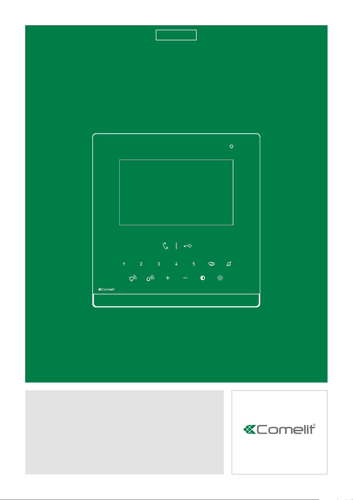
Icona door entry monitor
Art. 6601W - Art. 6601W/BM
Passion.Technology.Design.
Page 2

Table of contents
Warning
Table of contents ............................................................................. 2
Monitor description ......................................................................... 3
Soft-touch key activation ........................................................................4
Soft-touch key description ......................................................................4
Indicator LED description........................................................................4
Technical specifications ................................................................. 5
Installation ........................................................................................ 7
Mounting the Icona SBC monitor on flush-mounted box Art. 6117 ....7
Wall-mounting (Art. 6620) / on 503 series box/round box ....................8
Connections ..................................................................................... 9
Variant: connection of call repetition device Art. 1122/A .....................9
Monitor configuration ................................................................... 10
Standard configuration for soft-touch keys ........................................10
Activation/deactivation Doctor function ..............................................10
Activation/deactivation Hands-Free function ......................................10
Configuration of Main and Secondary internal units - DIP 8 of S2 ....11
Power supply configuration and management - DIP 7 of S2 .............11
Advanced monitor configuration ..........................................................12
Warning .............................................................................................12
Programming for intercom call ..........................................................12
Programming/deleting intercom address (selective intercom only)
12
Programming buttons for intercom call ..................................... 13
Direct programming of intercom call .........................................14
Programming keys for generic or coded actuator ............................15
Programming buttons for other functions .........................................16
Programming range ..........................................................................17
LED/alarm/lock-release/actuator programming ...............................18
Changing monitor ringtones .............................................................19
Programming reset ...........................................................................19
System performance and layouts ................................................ 19
2
Page 3
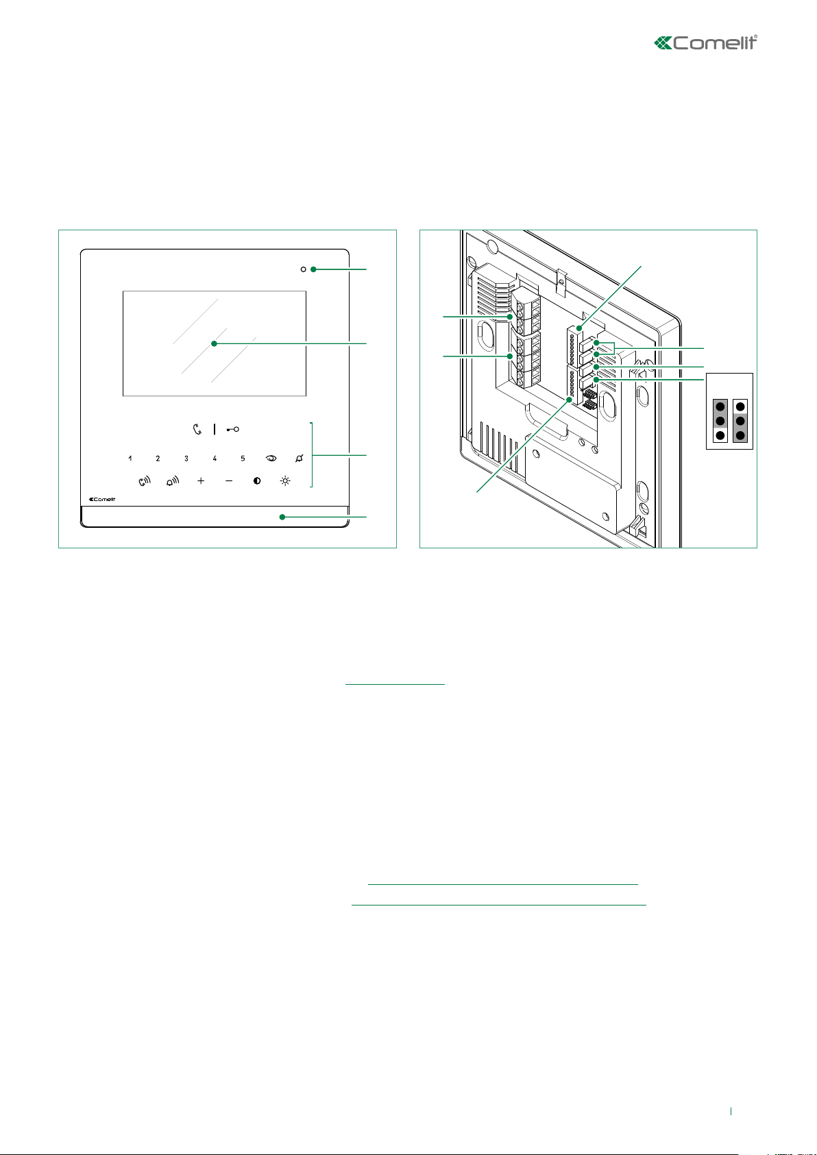
Monitor description
The Icona series is comprised of hands-free monitors that can be used in “Building Kit” (exclusively 2-wire), Simplebus Top and Kit
Video systems
• Article 6601W is a colour monitor equipped as standard with 9 function buttons and 6 adjustment buttons.
• Article 6601W/BM is a colour monitor equipped as standard with 9 buttons, 6 adjustment buttons and an induction loop.
1
11
2
10
3
9
4
5
6
7
8
1. Microphone
2. 4.3’’ LCD screen
3. Soft-touch keys/LED
4. Loudspeaker
5. S1 User code programming microswitches (see Addressing table)
6. CV1 CV2 remove in case of separate power supply.
7. CV5 Jumper for video closure. In systems with more than one monitor connected in cascade, only the monitor furthest
away must have CV5 closed.
8. CV6
position A = contact IN1-IN2 > LED (default)
position B = contact CFP2-IN1 > ALARM/LOCK-RELEASE/ACTUATOR
9. S2 Microswitches for programming buttons and functions (marked with a red corner)
DIP 1-2-3-4 for button function programming
DIP 5-6 access to programming
DIP 7 for management of power supply voltage, see
DIP 8
for main and secondary monitor setting, see “Configuration of Main and Secondary internal unit”
“Power supply configuration and management”
10. M2 Terminal block for system connection:
CFP1 CFP2 Floor door call input
S+ S- Call repetition device terminals
IN1 IN2 LED input (programmable)
11. M1 Terminal block for system connection:
L L Bus line connection terminals
- + Power supply terminals
BA
3
Page 4
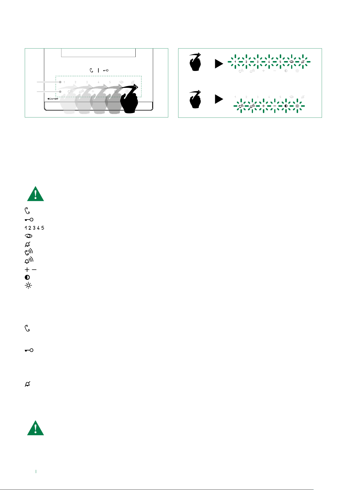
Soft-touch key activation
1
2
f Swipe to enable function key row (1).
f Swipe to enable function key row (2).
f Press the desired key once to activate the function associated with it
Soft-touch key description
Wait for approximately 1 sec. before pressing the same key again. Pressing the same key several times in quick
succession will cancel the command
x2
Audio key
Lock-release key
Keys 1-2-3-4-5 (programmable)
Self-ignition key (programmable)
Privacy key
Call volume key
Ringtone volume key
Value 'Up/Down' key
Contrast key
Brightness key
Indicator LED description
Audio LED
steady = audio enabled/hands-free function
continuous flashing = call received
Lock-release LED
1 flash = confirm lock-release
4 flashes = programming successful
10 flashes = programming error
continuous flashing = door open
Privacy LED - Doctor
4 flashes = device engaged
slow flashing = programming
3 flashes (every 5 s.) = Doctor function enabled
steady = privacy function enabled
The monitor Art. 6601W is designed for use in colour systems, in the SB2 section downstream of Art. 4888C, or in
systems without mixer, such as the system with 2-wire KIT or Art. 1210.
4
Page 5

Technical specifications
MAIN SPECIFICATIONS 6601W 6601W/BM
Flush-mounted Yes Yes
Wall-mounted Yes Yes
Desk base-mounted Yes Yes
Hands-free function Yes Yes
Induction loop / Yes
Type of display LCD LCD
Display size (inches) 4,3'' 16:9 4,3'' 16:9
Display resolution (H x V) 480 x 272 480 x 272
B/W or colour display Colors Colors
Product colour White RAL9003 White RAL9003
Sensitive Touch technology Yes Yes
Total buttons 15 15
COMPATIBILITY
Simplebus Top audio/video system Yes Yes
Building Kit audio/video system Yes Yes
Kit audio/video system Yes Yes
FUNCTIONS
Actuator control function Yes Yes
Self-ignition Yes Yes
Switchboard call function Yes Yes
Priority calls Yes Yes
Intercom function Yes Yes
Selective intercom call Yes Yes
Call to multiple addresses Yes Yes
Call to group addresses Yes Yes
Call forwarding Ye s Yes
Privacy function Ye s Yes
Doctor Ye s Yes
Redial Ye s Yes
Floor door call function Ye s Yes
Electronic bell Ye s Yes
Customisable ringtone Ye s Yes
Privacy conversation function Ye s Yes
Key button function Ye s Yes
HARDWARE SPECIFICATIONS
Removable terminals Ye s Yes
SETTINGS
Loudspeaker volume control Yes Yes
Microphone volume control Yes Yes
Ringtone volume control Yes Yes
Display brightness control Ye s Yes
Display contrast control Yes Yes
5
Page 6

GENERAL INFO 6601W 6601W/BM
Product height (mm) 147 147
Product width (mm) 142,5 142,5
Product depth (mm) 23 23
TECHNICAL SPECIFICATIONS
Power supply voltage 22÷28Vdc 22÷28Vdc
Operating temperature (°C) -5÷40 -5÷40
Relative humidity for operation 25 - 75 % 25 - 75 %
Clamps L L - + CFP1 CFP2 S+ S- IN1 IN2 L L - + CFP1 CFP2 S+ S- IN1 IN2
6
Page 7

Installation
CLACK !
Mounting the Icona SBC monitor on flush-mounted box Art. 6117
14,2 cm
14,7 cm
160 cm
130 cm
1
2
3
5
1
4
4
2
L
= 6 cm
min
L
= 10 cm
max
5
2
2
1
3
2
1
6
2
1
2
1
7
1
2
8
9
1
DISASSEMBLY
7
Page 8

Wall-mounting (Art. 6620) / on 503 series box/round box
CLACK !
130 cm
14,2 cm
1
with Art.6620*
L
min
L
= 6,5 cm
max
= 7 cm
14,7 cm
2
with Art.6620*
160 cm
1
with Art.6620*
3A
2
1
2
2
4A
3C
1
5A
2
1
1
6
3B
2
2
1
7
* Art. 6620 (optional)
2
1
2
1
1
2
8
8
DISASSEMBLY
Page 9

Connections
ADDITIONAL POWER
SUPPLY (IF NECESSARY)
VIDEO ENTRY
SYSTEM RISER
L
L
OUT
OUT
L
INLIN
CV1CV2
1214/2C
LM
LM
ADDITIONAL RINGER
2
0
2
3
0
0
0
1212/B
FLOOR DOOR CALL
C
IN
IN
LL
+
-
2 1
S+S
-
C
F
F
2
1
P
P
1229
6601W
PROGRAMMABLE INPUT
CV6
A
VIDEO ENTRY
B
SYSTEM RISER
20 m MAX - Connect only one call repetition device for each user code.
20 m MAX - Use shielded cable for the connection and do not route the cables in the vicinity of heavy inductive loads
or power supply cables (230V/400V).
Where multiple door-entry phones or monitor backplates have the same user code, connect the CFP button on one
only; all the devices will ring simultaneously.
For the programming procedure, see paragraph: LED/alarm/lock-release/actuator programming
Variant: connection of call repetition device Art. 1122/A
C
S+S
-
C
F
F
2
1
P
P
+
NON
C
-
C
1122/A
(12V)
IN
+
LL
-
IN
2 1
12/24V
AC/DC
20 m MAX - Connect only one call repetition device for each user code. If inductive loads are connected, the
connection of 470nF capacitance in parallel with the C-NO contacts of Art. 1122/A is advisable.
9
Page 10

Monitor configuration
Legend
0 DIP-switch OFF
1 DIP-switch ON
Lock- release
Audio
ACT Actuator
AI
CCP Main switchboard call [not for use in systems with KIT]
CCS Secondary switchboard call [not for use in systems with KIT]
K Guardian doorentry phone call
D Doctor
PAN Panic [not for use in systems with KIT]
INT General or selective programmable intercom [general internal call as standard for KIT and Simplebus Top]
INTb Two-family intercom [for KIT only]
NULL No function
PROG
** Press and hold to enable/disable the function
Self-ignition
Programmed functions, see "Advanced monitor configuration".
In this DIP switch setting, the buttons control the programmed functions; the NON-programmed buttons
control functions referred to on line 0000 (default).
**
Standard configuration for soft-touch keys
DIP S2
DIP 1 DIP 2 DIP 3 DIP 4
0 0 0 0 AI
1 0 0 0 AI ACT INT INTb D CCS
0 1 0 0 AI INT INTb ACT CCS CCP
1 1 0 0 CCS ACT CCP PAN K D
0 0 1 0 ACT ACT ACT ACT ACT ACT ACT
1 0 1 0 ACT
0 1 1 0 D AI K CCS CCP INTb
1 1 1 0 INT INTb AI INT PAN D
0 0 0 1 PAN CCS D AI INT INTb
1 0 0 1 CCS K PA N CCP AI INT
0 1 0 1 K CCP PAN ACT INT AI
1 1 0 1 CCP PAN CCS K ACT D
0 0 1 1 INTb D INT ACT AI CCS
1 0 1 1 INT INT INT INT INT INT
0 1 1 1 NULL NULL NULL NULL NULL NULL NULL NULL
1 1 1 1 PROG
Standard configuration for DIP switches 1-2-3-4
P1 P2 P3 P4 P5
CCS ACT D PA N K
INT CCS CCP INTb PAN
Activation/deactivation Doctor function
f Press and hold (4 s.) the programmed key (Default key 3)
» (ACTIVATION)
» (DEACTIVATION) BEEP
+ 3 flashes every 5 s.
Activation/deactivation Hands-Free function
f Press and hold (4 s.) on the audio activation key
» (ACTIVATION) + audio LED with FIXED ILLUMINATION
» (DEACTIVATION) BEEP +
10
LED OFF
Page 11

Configuration of Main and Secondary internal units - DIP 8 of S2
f To configure an internal unit as the main unit, set DIP8 of S2 to OFF.
f To configure an internal unit as a secondary unit, set DIP8 of S2 to ON.
DIP 8
(S2)
OFF
DIP 8
(S2)
ON
In systems with Art. 1209 or Art. 1210, you can configure a maximum of 1 main monitor (+ 3 separately powered)
while in systems with Art. 4888C you can configure a maximum of 2 main monitors (+ 1 powered separately).
Power supply configuration and management - DIP 7 of S2
f For correct power management, the DIP switch should be set in accordance with the type of system and its configuration:
• in systems with power supply units 1209 and1210: always set the DIP switch to ON
• in systems with power supply unit 4888C: for secondary internal units, always set the DIP switch to OFF, for main
internal units, follow the indications given in the examples in the figure below:
A. 1 main internal unit,
B. 2 main internal units,
C. 3 main internal units of which 1 is powered separately.
A
B
C
4888C
DIP 7
(S2)
DIP 7
(S2)
DIP 7
(S2)
OFF
ON
ON
DIP 7
(S2)
DIP 7
(S2)
DIP 7
(S2)
OFF
OFF
OFF
DIP 7
(S2)
DIP 7
(S2)
DIP 7
(S2)
OFF
OFF
ON
11
Page 12

Advanced monitor configuration
DIP OFF
DIP ON
Warning
If the default settings (see table “Standard configuration for soft-touch keys” do not reflect requirements, the keys can be
programmed dierently by carrying out the steps below.
At the end, set S2 DIP switches 1-2-3-4 to the combination 1111 (PROG setting in the configuration tables “Advanced
monitor configuration”. In this DIP switch setting, the keys control the programmed functions; the NON-programmed
keys control functions referred to on line 0000 (see table “Standard configuration for soft-touch keys”. Restore the user
code setting on S1, see Addressing table.
Programming for intercom call
General intercom: function allowing calls to one or more internal units identified by the same call address as used
by the external unit.
Selective intercom: function allowing calls to one or more internal units identified by a dedicated call address (see
table B) which is different from the one used by the external unit.
General and selective intercoms CANNOT be used together on the same riser.
Programming/deleting intercom address (selective intercom only)
Take note of the S2, S1 setting and restore it when programming is complete
1) 2) 3)
Programming; set code,
TABLE B
S1
Cancellation
S1
Selective intercom addresses
You must set the intercom address on all the riser’s internal units.
You can assign the same intercom address to a maximum of 3 internal units.
For group calls, select the desired intercom codes simultaneously (max. 3).
Code DIP switch ON S1 Code DIP switch ON S1
S2 DIP
1 2 3 4 5 6
0 0 0 1 1 1
S2 DIP
1 2 3 4 5 6
1 1 1 1 1 1
TAB. B
S2
S2
x4
x10
12
1 1
2 2 6 6
3 3 7 7
4 4 8 8
5 5
Page 13

Programming buttons for intercom call
DIP S2 DIP S1
DIP 1DIP 2DIP 3DIP
4
P1 P2 P3 P4 P5
0 0 0 0
1 0 0 0 INT INTb
0 1 0 0 INT INTb
1 1 0 0
0 0 1 0
1 0 1 0
INT INTb
0 1 1 0 INTb
1 1 1 0 INT INTb INT
0 0 0 1 INT INTb
1 0 0 1 INT
0 1 0 1 INT
1 1 0 1
0 0 1 1 INTb INT
1 0 1 1 INT INT INT INT INT INT
0 1 1 1
ADDRESS
1 1 1 1 PROG
Example 1 - all systems (INCLUDING KITS!) - General intercom
on a monitor with user code 5, P2 programming = general internal call, P3 = general intercom with address 9
Example 2 - Selective intercom
on a monitor with user code 1 and intercom address 1, P2 programming = selective intercom with address 2, P3 = selective
intercom with address 3
1. Set S2 DIP switches 6 to the combination 1.
» the privacy LED
S2 DIP
1 2 3 4 5 6
0 0 0 0 0 1
flashes.
S2
2. Refer to the table “Programming buttons for intercom call” and select a combination in which the intercom function
(either INT or INTb) is listed for the buttons you wish to program.
EXAMPLE 1: for P2= general internal call, set S2 DIP switches 1-2-3-4 to the combination 1000 or 0011 or 1011 (P2=INT)
or 0100 (P2=INTb) and set S1 with address 5 as per Addressing table, then go to point 3
EXAMPLE 1: for P3= general intercom, set S2 DIP switches 1-2-3-4 to the combination 1110 or 1011 (P3=INT) or 1000
(P3=INTb) and set S1 with address 9 as per Addressing table, then go to point 3
EXAMPLE 2: for P2= selective intercom, set S2 DIP switches 1-2-3-4 to the combination 1000 or 0011 or 1011 (P2=INT)
and set S1 with address 2 as per table B, then go to point 3
EXAMPLE 2: for P3= selective intercom, set S2 DIP switches 1-2-3-4 to the combination 1110 or 1011 (P3=INT) and set S1
with address 3 as per table B, then go to point 3.
3. Press and release the key to be associated with the function
» the lock-release LED
flashes 4 times.
» a confirmation tone will sound.
4. To exit programming mode, set S2 DIP switches 5-6 to the combination 00
» the privacy LED
switches o
5. When programming is complete, set S2 DIP switches 1-2-3-4 to the combination 1111. Restore the user code
setting on S1, see table Addressing table.
13
Page 14

Direct programming of intercom call
Allows direct programming of intercom call via the internal units.
√ Requires 2 operators
Step 1: enter programming mode
Operator 1 and Operator 2 carry out the following procedures on 2 internal units:
1. Set S2 DIP switches 1-2 -3-4 to the combination 1111
2. Press and hold buttons 1 and 3 for 2 sec.
» The internal unit emits 1 tone.
» The privacy LED
flashes.
» The audio button LED lights up.
» The internal unit enters audio mode.
» At this point the 2 operators will be communicating with each other.
Step 2: intercom call programming
Operator 1:
f Press the key you want to program to call operator 2 (e.g. 2).
» The internal unit manned by operator 1 emits a confirmation tone.
Operator 2:
f Press the key you want to program to call operator 1 (e.g. 1).
» The internal unit manned by operator 2 emits a confirmation tone.
Operator 1/ Operator 2:
f Press the audio key
» The audio button LED
.
goes OFF.
» Programming of the 2 internal units is now complete.
To program another internal unit, move on to STEP 3.
Step 3: programming other internal units
Operator 1/ Operator 2:
1. Once the new station has been reached, carry out step 1 to begin communication
2. Repeat step 2
NOTE If a call is received during programming, it must be answered and the programming procedure resumed
afterwards.
14
Page 15

Programming keys for generic or coded actuator
DIP S2 DIP S1
DIP 1DIP 2DIP 3DIP
4
0 0 0 0
P1 P2 P3 P4 P5
ACT
1 0 0 0 ACT
0 1 0 0 ACT
1 1 0 0 ACT
0 0 1 0 ACT ACT ACT ACT ACT ACT ACT
1 0 1 0 ACT
0 1 1 0
1 1 1 0
0 0 0 1
1 0 0 1
0 1 0 1 ACT
1 1 0 1 ACT
0 0 1 1 ACT
1 0 1 1
0 1 1 1
ADDRESS
1 1 1 1 PROG
Example:
on a monitor with user code 5, P1 programming = generic actuator,
= coded actuator (code 125)
Take note of the DIP-switch settings
1. Set S2 DIP switches 6 to the combination 1.
» the privacy LED
S2 DIP
1 2 3 4 5 6
0 0 0 0 0 1
flashes.
S2
2. Refer to the table “Programming keys for generic or coded actuator”select a combination in which the actuator
function (ACT) is listed for the buttons you wish to program.
E.g.: for P1= generic actuator, set S2 DIP switches 1-2-3-4 to the combination 1000 or 1100 or 0010 (P1=ACT), set S1 DIP
switches to the combination 11111111, then go to point 3.
E.g.: for = coded actuator (code 125), set S2 DIP switches 1-2-3-4 to the combination 0010 or 1010 ( =ACT), set S1
with address 125 as per Addressing table, then go to point 3.
3. Press and release the key to be associated with the function.
» the lock-release LED
flashes 4 times.
» a confirmation tone will sound.
4. To exit programming mode, set S2 DIP switches 5-6 to the combination 00.
» the privacy LED
switches o.
5. When programming is complete, set S2 DIP switches 1-2-3-4 to the combination 1111. Restore the user code
setting on S1, see Addressing table.
15
Page 16

Programming buttons for other functions
DIP S2 DIP S1
DIP 1DIP 2DIP 3DIP
4
P1 P2 P3 P4 P5
0 0 0 0 AI CCS D PAN K
1 0 0 0 AI D CCS
0 1 0 0 AI CCS CCP
1 1 0 0 CCS CCP PA N K D
0 0 1 0
1 0 1 0
CCS CCP PAN
0 1 1 0 D AI K CCS CCP
1 1 1 0 AI PAN D
0 0 0 1 PAN CCS D AI
1 0 0 1 CCS K PAN CCP AI
0 1 0 1 K CCP PAN AI
1 1 0 1 CCP PAN CCS K D
0 0 1 1 D AI CCS
1 0 1 1
0 1 1 1 NULL NULL NULL NULL NULL NULL NULL
1 1 1 1 PROG
ADDRESS
Example:
on a monitor with user code 5, P4 programming = self-ignition, P5 = Secondary switchboard call.
1. Set S2 DIP switches 6 to the combination 1.
» the privacy LED
S2 DIP
1 2 3 4 5 6
0 0 0 0 0 1
flashes.
S2
2. Refer to the table “Programming buttons for other functions” and select a combination in which the desired/necessary
functions are listed for the buttons you wish to program.
E.g.: for P4= self-ignition, P5= Secondary switchboard call, set S2 DIP switches 1-2-3-4 to the combination 0011 (P4=AI,
P5=CCS).
3. Press and release the keys to which you wish to assign the functions
» the lock-release LED
flashes 4 times.
» one confirmation tone is emitted.
4. To exit programming mode, set S2 DIP switches 5-6 to the combination 00
» the privacy LED
switches o.
5. When programming is complete, set S2 DIP switches 1-2-3-4 to the combination 1111.
16
Page 17

DIP OFF
DIP ON
Programming range
Take note of the S2, S1 setting and restore it when programming is complete
f Carry out steps 1 to 4
1) 2) 3) 4)
Range
minimum
address
Range
maximum
address
Enable range
Disable range
S2 DIP
1 2 3 4 5 6
0 0 0 0 1 0
S1
S2
set code, Addressing
table
x4
S2
2 sec
x10
2 sec
S2 DIP
1 2 3 4 5 6
1 1 1 1 1 0
Deleting the
range
S1
S2
17
Page 18

LED/alarm/lock-release/actuator programming
DIP OFF
DIP ON
Take note of the S2, S1 setting and restore on completion of programming
f Carry out steps 1 to 4
1) 2) 3) 4)
Input IN 1- IN 2
LED (default)*
Input CFP2 - IN 1
ALARM*
Input CFP2 - IN 1
LOCK-RELEASE*
Input CFP2 - IN 1
CODED ACTUATOR*
S1
set code,
Addressing table
1 2 3 4 5 6
0 0 0 1 1 0
S2
1 2 3 4 5 6
0 0 1 0 1 0
S2
S2 DIP
S2 DIP
x4
S2
x10
Input CFP2 - IN 1
GENERIC ACTUATOR*
* See "Connections".
S1
18
Page 19

Changing monitor ringtones
DIP OFF
DIP ON
1. Keep the
by; otherwise the signalling LED will flash to warn the user)
2. Press and release the
once (1 confirmation tone is emitted) to change the ringtone of calls from the external unit.
twice (2 confirmation tones are emitted) to change the ringtone for calls from the switchboard.
3 times (3 confirmation tones are emitted) to change the ringtone for intercom calls made from the internal unit.
4 times (4 confirmation tones are emitted) to change the floor door (“CFP”) call ringtone.
Any further pressing of the repeats the sequence described above.
3. Press and release button 1 to scroll through the various available ringtones in sequence.
4. Press button 2 to confirm selection of the last ringtone heard and to exit (at any time) the monitor ringtone change mode.
On exiting the monitor ringtone selection mode a confirmation tone will be emitted.
Programming reset
Factory settings:
• Button functions for the S2 DIP switch 1-2-3-4 combination;
• Intercom address absent;
• Range function and min./max. addresses absent;
• Ringtone reset.
• Input IN 1 - IN 2 > LED (default).
• Doctor, Privacy and Hands Free functions disabled.
button pressed until a confirmation tone is emitted (this operation is only possible with the system in stand-
button:
Take note of the S2, S1 setting and restore on completion of programming
1) 2) 3)
S1
S2 DIP
1 2 3 4 5 6
1 1 1 1 1 1
S2
x4
System performance and layouts
For further information of system performance and to view installation layouts, click on the type of system that best meets your
needs:
• Audio/video kit for the creation of audio-video systems for individual residences.
• Building Kit audio/video system for the creation of audio-video systems for small apartment blocks.
• SBTOP audio/video system for the creation of audio-video systems for residential complexes.
19
Page 20

4ª edizione 05/2018
cod. 2G40002156
CERTIFIED MANAGEMENT SYSTEMS
www.comelitgroup.com
Via Don Arrigoni, 5 - 24020 Rovetta (BG) - Italy
 Loading...