

Page 1
EN
TECHNICAL
MANUAL
Audio/video module for SBTOP system
Art. 4680C, 1622VC, 1622VCF
Passion.Technology. Design.
Page 2

Warning
Intended use
This Comelit product was designed for use in the creation of audio and video communication systems in residential,
commercial or industrial settings and in public buildings or buildings used by the public.
Installation
All activities connected to the installation of Comelit products must be carried out by qualified technical personnel, with
careful observation of the indications provided in the Manuals / Instruction sheets supplied with those products.
Wires
Cut o the power supply before carrying out any maintenance procedures.
Use wires with a cross-section suited to the distances involved, observing the instructions provided in the system
manual.
We advise against running the system wires through the same duct as the power cables (230V or higher).
Safe usage
To ensure Comelit products are used safely:
• carefully observe the indications provided in the Manuals / Instruction sheets
• make sure the system created using Comelit products has not been tampered with / damaged.
Maintenance
Comelit products do not require maintenance aside from routine cleaning, which should be carried out in accordance
with the indications provided in the Manuals / Instruction sheets.
Any repair work must be carried out
• for the products themselves, exclusively by Comelit Group S.p.A.,
• for systems, by qualified technical personnel.
Disclaimer
Comelit Group S.p.A. does not assume any responsibility for
• any usage other than the intended use
• non-observance of the indications and warnings contained in this Manual / Instruction sheet.
Comelit Group S.p.A. nonetheless reserves the right to change the information provided in this Manual / Instruction
sheet at any time and without prior notice.
Table of contents
Warning ............................................................................................ 2
Description ....................................................................................... 3
Art. 4680C - Compatibility table .........................................................3
Art. 1622VC/1622VCF - Compatibility table .......................................3
Connecting the remote camera .............................................................4
Technical characteristics ................................................................ 5
External unit installation ................................................................. 7
Connections ..................................................................................... 9
4680C/1622VC/1622VCF connections ....................................................9
Remote camera connection (Art. 1622VC / 1622VCF only) ..................9
Variants ...................................................................................................10
Module connection ........................................................................ 11
Ikall / Ikall Metal modules......................................................................11
Connection of button modules 33433, 33434, 33436, 33433M,
33434M, 33436M ..............................................................................11
Connection of Art.3348B, 3348BM ..................................................11
Connection of Art.3360B, 3360BM ..................................................11
Vandalcom modules...............................................................................12
Connection of Art.3064S .................................................................12
Connection of Art.3188SB ...............................................................12
Connection of Art.3070S, 3072S .....................................................13
Modules for Single-plate external unit .................................................13
Connection of Art.3063D .................................................................13
Button programming ..................................................................... 14
Special programmes ..................................................................... 15
Installation information ..........................................................................17
System performance and layouts ................................................ 17
2
Page 3
Description
Article 4680C is a colour audio-video module which is compatible with Comelit “SBTOP” video entry systems, exclusively for
use in conjunction with riser power supply unit Art. 4888C.
It can be installed in Ikall, Ikall Metal, Vandalcom, Roma external units and can be finished with additional modules to meet all
system requirements.
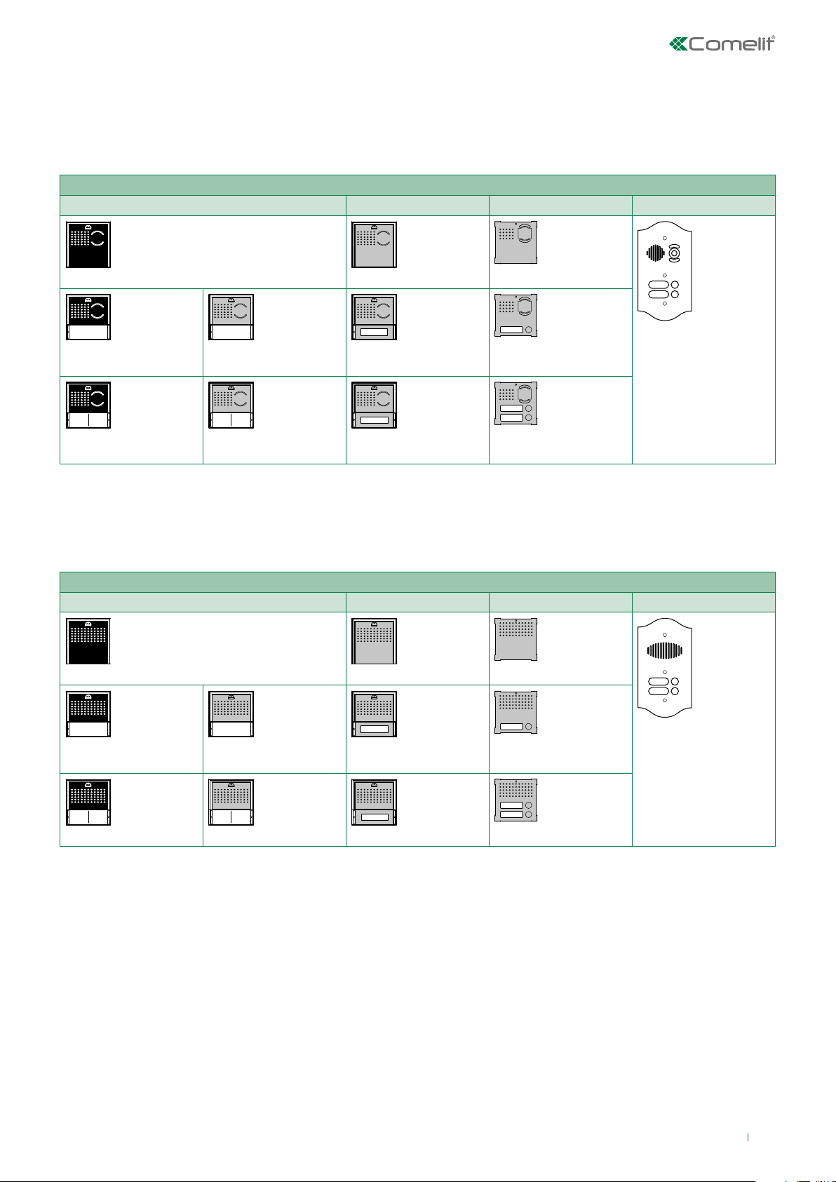
Art. 4680C - Compatibility table
Ikall Ikall Metal Vandalcom Roma
33410
33411
33412
Item 1622VC/1622VCF is an audio module allowing connection of a remote colour PAL camera. It is compatible with Comelit
“SBTOP” video entry systems, exclusively for use in conjunction with riser power supply unit Art. 4888C.
It can be installed in Ikall, Ikall Metal, Vandalcom, Roma external units and can be finished with additional modules capable of
fulfilling all system requirements.
Art. 1622VC/1622VCF - Compatibility table
Ikall Ikall Metal Vandalcom Roma
33400
33411A
33412A
33410M
33411M
33412M
33400M
3268S/0
3268S/1
3268S/2
3262S/0
32xx/RI
33401
33402
To make use of the indicator LEDs (busy, call sent, door opened, communication active), faceplates from kit 33400K are
available to purchase separately for the IKALL series.
33401A
33402A
33401M
33402M
3262S/1
3262S/2
30xx/RI
3
Page 4
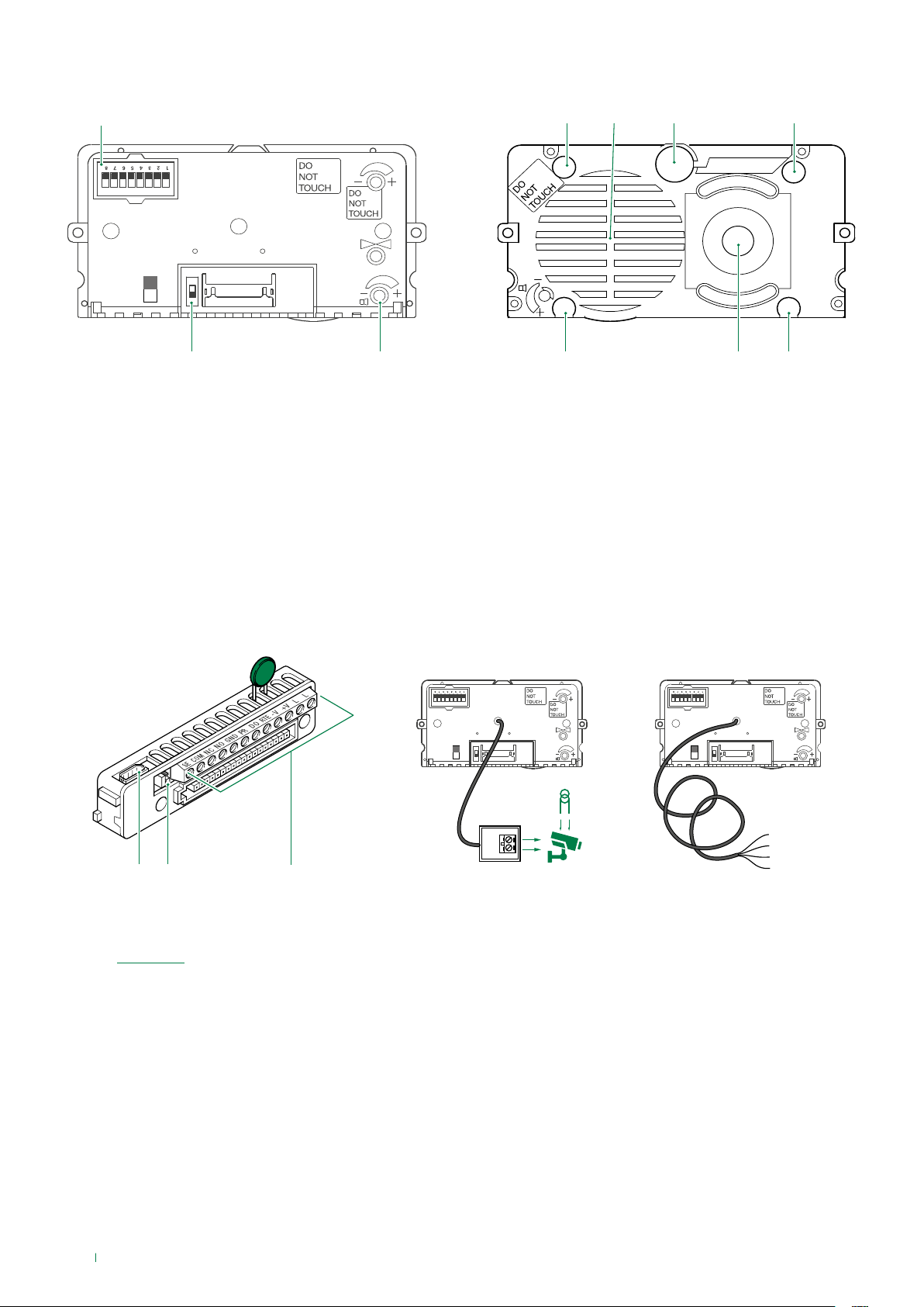
1. DIP switches for function programming and setting the
4. 7.
8.9.10.
6.5.
ON DIP
ON
OFF
1.
2. 3.
11. 12.
13.
user code.
2. Switch for confirming special programmes.
3. Loudspeaker volume control.
4. Indicator LED: call sent.
5. Loudspeaker.
6. Microphone.
7. Indicator LED: system busy.
8. Indicator LED: sound activated.
9. Colour camera (with Art. 4680C only).
10. Indicator LED: lock-release activated.
Art. 1622VCFArt. 1622VC
ON DIP ON DIP
11. 8-pole cable connector.
12. RC network control for door lock filter on relay contacts
(see “Variants”).
13. Terminal block for connection:
SE electric lock connection
COM common relay contact
NC normally closed relay contact
NO normally open relay contact
GND input reference negative for DO-RTE
PR programming input
DO door opened signal input
RTE local lock release input
V- power supply negative
V+ power supply positive
LL bus line connection
ON
OFF
S
V
ON
OFF
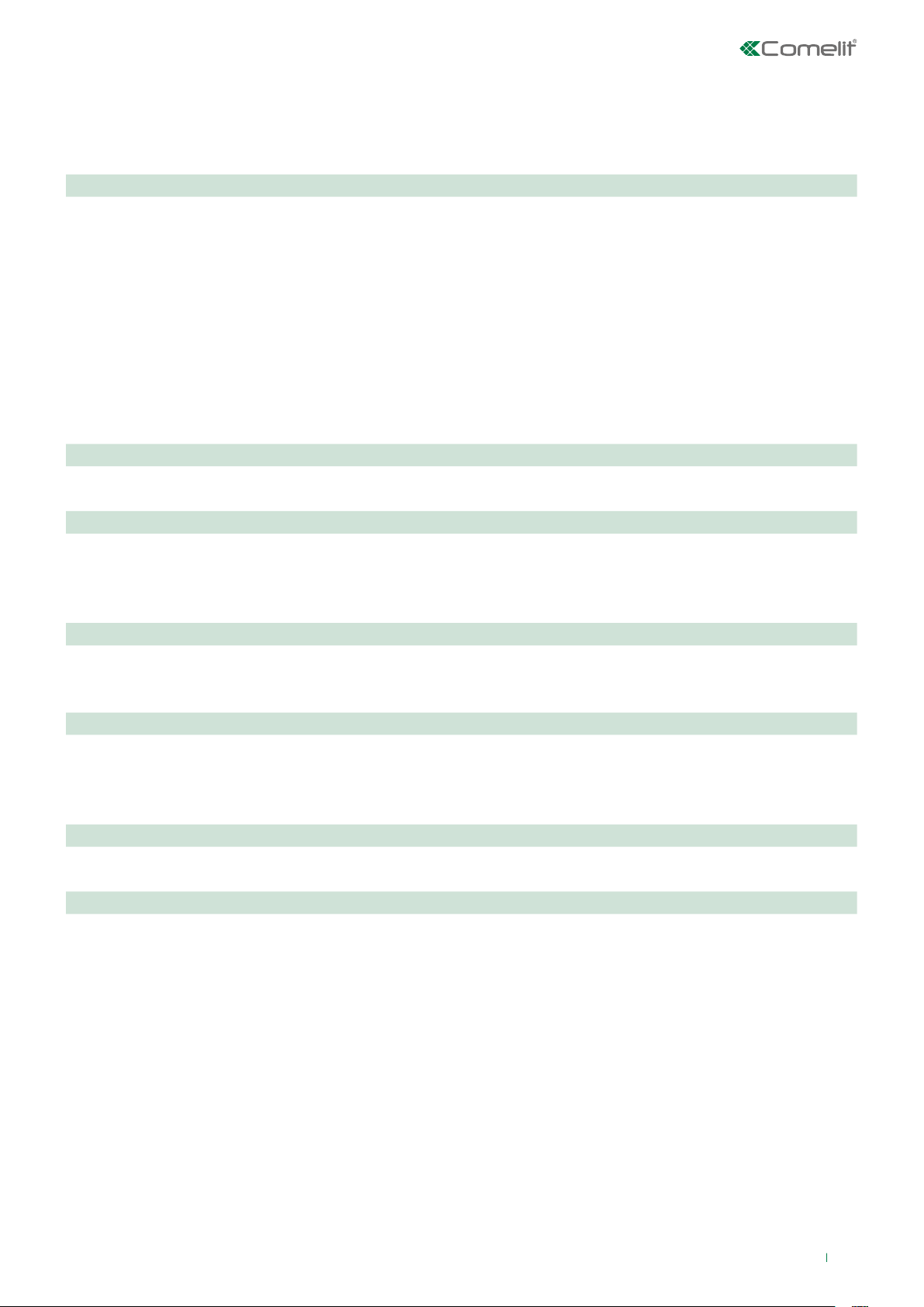
RED = +12V
BLACK = GND
WHITE = Video
BLUE = Vshield
Connecting the remote camera
Art. 1622VC is supplied with a cable for the connection of a
separately powered remote camera.
Art. 1622VCF is supplied with a cable for the connection of a
camera powered by the external unit (12 V-150 mA MAX).
4
Page 5
Technical characteristics
Art. 4680C
MAIN FEATURES
Audio/video system Yes
Horizontal resolution (TVL) 540
Minimum illumination (lux) 0.35
Lens size (mm) 3.60
Camera orientation Yes
Clamps L L V+V- RTE DO PR GND SE COM NC NO
Microphone volume control Yes
Loudspeaker volume control Yes
Operating temperature (°C) -25 ÷ 55
S/N ratio (dB) 48
FUNCTIONS
Key button function Yes
HARDWARE SPECIFICATIONS
Visual signalling Ye s
Acoustic signalling Yes
Speech synthesis Yes
SETTINGS
Loudspeaker volume control Yes
Microphone volume control Yes
GENERAL DATA
Product height (mm) 55
Product width (mm) 102
Product depth (mm) 38
COMPATIBILITY
Simplebus Top audio/video system Ye s
ELECTRICAL SPECIFICATIONS
Door release (dry contact bridge) Yes
Door release (direct current output) Yes
5
Page 6

Art. 1622VC Art. 1622 VCF
MAIN FEATURES
Audio/video system Yes Yes
Clamps
L L V+V- RTE DO PR GND SE COM NC NO L L V+V- RTE DO PR GND SE COM NC NO
Microphone volume control Yes Yes
Loudspeaker volume control Yes Yes
Operating temperature (°C) -25 ÷ 55 -25 ÷ 55
FUNCTIONS
Key button function Yes Yes
HARDWARE SPECIFICATIONS
Visual signalling Ye s Ye s
Acoustic signalling Yes Yes
Speech synthesis Yes Yes
SETTINGS
Loudspeaker volume control Yes Yes
Microphone volume control Yes Yes
GENERAL DATA
Product height (mm) 55 55
Product width (mm) 102 102
Product depth (mm) 38 38
COMPATIBILITY
Simplebus Top audio/video system Ye s Ye s
ELECTRICAL SPECIFICATIONS
Door release (dry contact bridge) Yes Yes
Door release (direct current output) Yes Ye s
6
Page 7

External unit installation
40-45 cm
59°
163 cm
130 cm
87°
1
The camera must not be installed in front of light sources, or in places where the filmed subject is against
the light.
In dim environments, we recommend additional lighting is provided.
3 42
163 cm
130 cm
Connect the module support frame to earth.
1
Art. 1622VC
3
1
Art. 1622VCF
RED = +12V
BLACK = GND
WHITE = Video
2
5
BLUE = Vshield
12 V
MAX 150 mA
7
Page 8

3
2
5
4
SOLO MT COMPLETO
LED
O
F
F
WHITE OFF
LED
O
F
F
Nameplate LED lighting
selection.
2
1
BLUE
6
Alternative microphone
position (excluding 4
module entrance panel).
3
1
3
Close
7
2
360°
Open
8
Page 9

Connections
-
4680C/1622VC/1622VCF connections
-
+
120-230 V
1595
C
S
O
NC
NO
E
M
R
G
D
VV
T
N
RPO
D
+
E
VIDEO ENTRY SYSTEM RISER
LL
4680C 1622VC
20 m max. Local lock-release button.
Active input closed for DOOR OPEN signal.
Remote camera connection (Art. 1622VC / 1622VCF only)
1622VCF
ON DIP
ON
OFF
SV
~
1622VC
ON DIP
ON
OFF
1622VCF
RED
BLACK
WHITE
BLUE
9
Page 10

Variants
-
-
Jumper
Variant for using the external unit relay
230 V
R
G
D
T
N
RPO
E
D
12V/24V
AC-DC
10A MAX
C
S
O
NC
NO
E
M
“C.NC.NO relay activation on
actuator command: 2 sec”
Set dip switches in permanent
mode as shown in figure (Dip
switch 8 ON, Dip switches
1,2,3,4,5,6,7 OFF)
(Applies to Art. 4680C with R.I.
041 or greater)
VV
LL
+
4680C 1622VC
1622VCF
Variant for using a safety lock
12/24V
AC/DC
C
S
O
NC
NO
E
M
RPO
R
D
VV
T
+
E
G
N
D
4680C 1622VC
1622VCF
LL
On C. NO. contacts On C. NC. contacts Excluded: voltage-free contact
10
Page 11

M
E
-
D
Module connection
Ikall / Ikall Metal modules
Connection of button modules 33433, 33434, 33436, 33433M, 33434M, 33436M
4680C
1622VC
1622VCF
J1
J2
J1
J2
Connection of Art.3348B, 3348BM
+
-
1595
120-230 V
C
G
S
O
N
NC
NO
E
4680C
1622VC
1622VCF
Connection of Art.3360B, 3360BM
RPO
R
D
T
VV
+
J1
J2
4680C
1622VC
1622VCF
VIDEO ENTRY SYSTEM RISER
LL
J1
J2
C
J1
J2
J1
J2
G
P
485
NDGR
D
-
485 24
S
+
D
2NO2NC2C1NO1NC1
Vac24Vac
3360B
3360BM
3 3 6
~+~
R
AL
C
D D
-
+
-
K
K
+
-
3348B
3
3348BM
987
11
Page 12

Vandalcom modules
-
-
Connection of Art.3064S
+
-
1595
VIDEO ENTRY SYSTEM RISER
120-230 V
J1
LL
J2
CV3
4680C + 3268S
1622VC / 1622VCF +3262S
C
S
O
NC
NO
E
M
R
G
D
VV
T
N
RPO
D
+
E
3064S
Use the cable supplied with Art. 3262S, 3268S
Use bulb Art. 1172B for nameplate lighting. The bulb is polarised.
J1
V
S
C
-
+
J2
S
-
J2
J1
V
C
+
3064S 3064S 3064S
1172B1172B1172B 1172B
V
S
C
-
+
Connection of Art.3188SB
+
-
120-230 V
C
G
S
O
N
NC
NO
E
M
D
4680C+3268S
1622VC+3262S
1622VCF+3262S
1595
RPO
VIDEO ENTRY SYSTEM RISER
3188SB
NO2
C2
NC2
NO1
C1
NC1
PGM
RK
-
R
D
VV
T
+
E
J1
LL
J2
CV3
J1 J1
V
S
C
-
+
J2
V
S
C
-
+
J2
N°1 N°2 N°15
J1
V
S
C
-
+
J2
MAX 15
3064S
3064S 3064S 3064S
MAX 15
1172B1172B1172B 1172B
~
~
+
-
CK
+
OUT
AC
-
AL
-
D
-
D
+
Use the cable supplied with Art. 3262S, Art. 3268S
MAX 15 modules.
Use bulb Art. 1172B for nameplate lighting. The bulb is polarised
12
Page 13

Connection of Art.3070S, 3072S
M
E
-
D
+
-
1595
VIDEO ENTRY SYSTEM RISER
120-230 V
C
S
O
NC
NO
E
R
G
D
VV
T
N
RPO
LL
+
4680C
1622VC
1622VCF
J1
12~12
J2
VV
+
S
-
~
"V-" BLUE
"S" YELLOW
"V+" BROWN
2E7T000696
Use the cable 2E7T000696 supplied with Art. 3070S, Art. 3072S
T
P
-
-
R
D
-
X
XR
+ +
-
12~12
VV
+
-
S
-
~
P
-
R X
3070S
R-T
D
DD
X
-
3072S
Modules for Single-plate external unit
Connection of Art.3063D
-
4680C
1622VC
1622VCF
+
120-230 V
1595
C
S
O
NC
NO
E
M
R
G
D
VV
T
N
RPO
D
+
-
E
VIDEO ENTRY SYSTEM RISER
J1
LL
J2
1172B
1172B
J1
J2
J1
V
S C
J2
+
P2P
1
P3P4P5P6P7P
8
-
3063D
N°1
J1
V
S C
+
P2P
1
P3P4P5P6P7P
8
-
3063D
N°X
3063D
CV2
Use the cable included in Art. 1250IV, Art. 1250IA
Use bulb Art. 1172B for nameplate lighting. The bulb is polarised
13
Page 14

Button programming
33436
1
33433
33434
2
Set the user code using the dip switches; see addressing table.
65
43
14
Page 15

Special programmes
+V
-V
GND
1
2
1 sec.
4 5
Set the dip switches for the function you wish to program, see table below
3
PR
6
GND
PR
7
15
Page 16

CODE DIP SWITCH ON FUCNTION
De-misting heating element
213 1,3,5,7,8 OFF (default)
212 3,5,7,8 ON
Audio-visual messages
210 2,5,7,8 visual messages only
211 1,2,5,7,8 Swedish
214 2,3,5,7,8 OFF (default)
215 1,2,3,5,7,8 Italian
216 4,5,7,8 French
217 1,4,5,7,8 Spanish
218 2,4,5,7,8 Dutch
219 1,2,4,5,7,8 Greek
220 3,4,5,7,8 English
221 1,3,4,5,7,8 German
222 2,3,4,5,7,8 Portuguese
202 2,4,7,8 Enables voice message (door opened warning) when the RTE contact is closed
203 1,2,4,7,8
Disables voice message (door opened warning) when the RTE contact is closed (default
setting)
Door lock
223 1,2,3,4,5,7,8 Door lock command on SE in AC (default)
224 6,7,8 Door lock command on SE in enhanced AC
225 1,6,7,8 Door lock command on SE in DC
245 1,3,5,6,7,8 Door lock time: 2 sec + deactivation tone (default)
246 2,3,5,6,7,8 Door lock time: 4 sec
247 1,2,3,5,6,7,8 Door lock time: 8 sec
248 4,5,6,7,8 Door lock confirmation tone: enabled
251 1,2,4,5,6,7,8 C.NC.NO relay in parallel with SE (default)
252 3,4,5,6,7,8 Lock-release always enabled (default)
253 1,3,4,5,6,7,8 Lock-release only enabled for user called
Actuator control management
N.B. the system should not include Art. 1256 in generic actuator mode.
229 1,3,6,7,8 Enabling C.NC.NO relay on actuator control: 2 sec
230 2,3,6,7,8 Enabling C.NC.NO relay on actuator control: 4 sec
231 1,2,3,6,7,8 Enabling C.NC.NO relay on actuator control: 8 sec
228 3,6,7,8 Actuator control on serial line S: disabled (default)
227 1,2,6,7,8 Actuator control on serial line S: enabled
System functions
232 4,6,7,8 Awaiting response time: 60 sec (default)
233 1,4,6,7,8 Awaiting response time: 120 sec
16
Page 17

234 2,4,6,7,8 Awaiting response time: 30 sec
235 1,2,4,6,7,8 Talk time: 90 sec (default)
236 3,4,6,7,8 Talk time: 180 sec
237 1,3,4,6,7,8 Self-ignition: enabled (default)
238 2,3,4,6,7,8 Self-ignition: disabled
239 1,2,3,4,6,7,8 Confirmation tone on user call: enabled (default)
240 5,6,7,8 Confirmation tone on user call: disabled
243 1,2,5,6,7,8 Reset wait time: 10 sec (default)
244 3,5,6,7,8 Reset wait time: 1 sec
208 5,7,8 Reset after lock-release in audio: enabled (default)
209 1,5,7,8 Reset after lock-release in audio: disabled
249 1,4,5,6,7,8 Call transmission: single (default)
250 2,4,5,6,7,8 Call transmission: triple
241 1,5,6,7,8 Control of internal units connected to Art. 4680C: up to 70 (default)
242 2,5,6,7,8 Control of internal units connected to Art. 4680C: from 71 to 100
System mode
000 Simplebus (default)
255 1,2,3,4,5,6,7,8 Simplebus Top
254 2,3,4,5,6,7,8 Restore default
Installation information
• The module Art. 4680C / 1622VC / 1622VCF operates by default as a main external unit (timed busy signal).
To set it as a secondary external unit (busy signal active for the whole time the riser is in use), set all the selector DIP
switches to ON.
• When a call is transmitted from the external unit, if a busy tone is heard instead of the ringtone, this means communication
with another external unit is in progress.
System performance and layouts
For further information of system performance and to view installation layouts, click on the type of system that best meets your
needs:
• SBTOP audio/video system for the creation of audio-video systems for residential complexes
17
Page 18

6ª edizione 05/2018
cod. 2G40002075
CERTIFIED MANAGEMENT SYSTEMS
www.comelitgroup.com
Via Don Arrigoni, 5 - 24020 Rovetta (BG) - Italy
 Loading...