

Page 1
INSTALLATION
& OPERATION
MANUAL
3920/25
SIREN
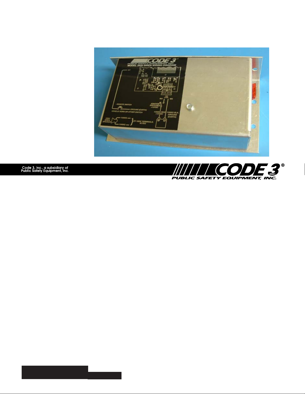
MODEL 3920/25
REMOTE COMPACT SIREN
Contents:
Introduction .............................................................. 2
Standard Features..................................................... 2
Unpacking & Pre-Installation ....................................... 3
Installation & Mounting ............................................... 3
Wiring ..................................................................... 4
Speaker Connections ............................................... 5
Operation ................................................................ 5
Specifications ........................................................... 6
Maintenance ............................................................ 7
Troubleshooting ........................................................ 7
Parts List (Replacement Parts / Exploded View) .............. 8
Notes ..................................................................9-11
Warranty ................................................................12
IMPORTANT:
Read all instructions and warnings before installing and using.
INSTALLER: This manual must be delivered to the end user of this equipment.
Page 2

Introduction
!
The Code 3® Model 3920 siren produces three distinct tones, "Wail", "Yelp"and "Hyper-Yelp". In addition, the siren
produces a momentary "Air Horn" tone. The siren features one remote input for selection/control of the siren tones
and "Air Horn" as well as Output Short Circuit Protection.
Sirens are an integral part of an effective audio/visual emergency warning system. However, sirens are only
short range secondary warning devices. The use of a siren does not insure that all drivers can or will observe
or react to an emergency warning signal, particularly at long distances or when either vehicle is traveling at a
WARNING!
SIREN PRODUCTS:
high rate of speed. Sirens should only be used in a combination with effective warning lights and never relied
upon as a sole warning signal. Never take the right of way for granted. It is your responsibility to be sure you
can proceed safely before entering an intersection, driving against traffic, or responding at a high rate of speed.
The effectiveness of this warning device is highly dependent upon correct mounting and wiring. Read and
follow the manufacturers instructions before installing or using this device. The vehicle operator should check
the equipment daily to insure that all features of the device operate correctly.
To be effective, sirens must produce high sound levels that potentially can inflict hearing damage. Installers
should be warned to wear hearing protection, clear bystanders from the area and not to operate the siren
indoors during testing. Vehicle operators and occupants should assess their exposure to siren noise and
determine what steps, such as consultation with professionals or use of hearing protection should be implemented to protect their hearing.
This equipment is intended for use by authorized personnel only. It is the user’s responsibility to understand
and obey all laws regarding emergency warning devices. The user should check all applicable city, state and
federal laws and regulations.
Code 3, Inc., assumes no liability for any loss resulting from the use of this warning device.
Proper installation is vital to the performance of the siren and the safe operation of the emergency vehicle. It is
important to recognize that the operator of the emergency vehicle is under psychological and physiological
stress caused by the emergency situation. The siren system should be installed in such a manner as to: A)
Not reduce the acoustical performance of the system, B) Limit as much as practical the noise level in the
passenger compartment of the vehicle, C) Place the controls within convenient reach of the operator so that he
can operate the system without losing eye contact with the roadway.
Emergency warning devices often require high electrical voltages and/or currents. Properly protect and use
caution around live electrical connections. Grounding or shorting of electrical connections can cause high
current arcing, which can cause personal injury and/or severe vehicle damage, including fire.
PROPER INSTALLATION COMBINED WITH OPERATOR TRAINING IN THE PROPER USE OF EMERGENCY WARNING DEVICES IS ESSENTIAL TO INSURE THE SAFETY OF EMERGENCY PERSONNEL
AND THE PUBLIC.
Standard Features
The 3920 Remote siren provides the following features:
Tones: Wail, Yelp, HyperYelp and Air Horn
Remote Siren Switching - The siren accepts a ground (earth) signal, from the vehicle's horn switch (or other
user supplied switch), and remotely activates the siren as described under the operation section.
2
Page 3
Unpacking & Pre-installation
!
After unpacking your 3920 siren, carefully inspect the unit and associated parts for any damage that may have occurred
in transit. Report any damage to the carrier immediately.
Installation & Mounting
The 3920 siren is designed to be remotely mounted in a cool dry location such as under a seat or in the trunk. The siren may
not be mounted in any location where it will be exposed to high heat or moisture. The 3920 siren is controlled by either proper
connection to the vehicle Horn Ring switch and/or by use of the optional remote switch panel. Ease of operation and
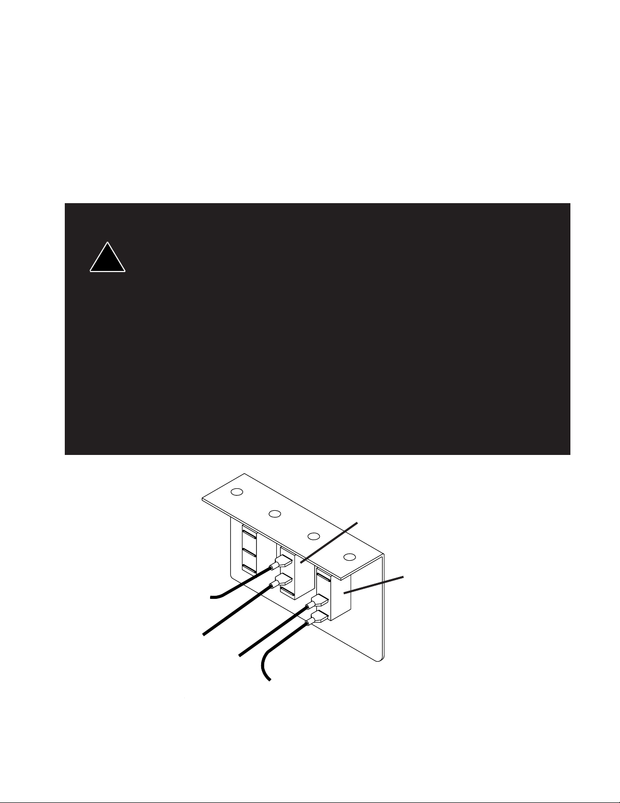
convenience to the operator should be prime consideration when mounting the siren and controls. Figure 1 shows the switch
panel.
All devices should be mounted in accordance with the manufacturer's instructions and
securely fastened to vehicle elements of sufficient strength to withstand the forces applied to
the device.
Ease of operation and convenience to the operator should be the prime consideration when
mounting the siren and controls. Adjust the mounting angle to allow maximum operator
WARNING!
visibility.
Do not mount the Control Head Module in a location that will obstruct the drivers view.
Mount the microphone clip in a convenient location to allow the operator easy access.
Devices should be mounted only in locations that conform to their SAE identification code as
described in SAE Standard J1849. For example, electronics designed for interior mounting
should not be placed underhood, etc.
Controls should be placed within convenient reach* of the driver or if intended for two person
operation the driver and/or passenger. In some vehicles, multiple control switches
and/or using methods such as "horn ring transfer" which utilizes the vehicle horn switch to
toggle between siren tones may be necessary for convenient operation from two positions.
*
Convenient reach is defined as the ability of the operator of the siren systems to manipulate
the controls from his normal driving/riding position without excessive movement way from the
seat back or loss of eye contact with the roadway.
SCROLL
SWITCH
SIREN OFF
14AWG YEL
TO
-REMOTE (W7)
14AWG BLK
GROUND
(EARTH)
14AWG RED
SIREN POWER
14AWG RED
IGNITION
SWITCHED
+12VDC
FIGURE 1
3
SWITCH
Page 4

The siren chassis should be mounted with user provided hardware appropriate for the chosen mounting
location.
NOTE: Wiring will be performed in subsequent steps that will require access to the interior of the
unit. Plan the installation accordingly.
Wiring
The 3920 siren provides six 1/4" Quickslide connections on the printed circuit board for power, control and
speaker connections. Each printed circuit board connection is clearly marked for easy identification. Wiring
connections are shown in Figure 2.
Provide a "service loop" of six to eight inches of each wire coming to the siren to allow easy removal and
access to the siren.
VEHICLE HORN
SWITCH*
100W
SIREN
SPEAKER
W7
SCROLL SWITCH*
14AWG
14AWG
GROUND
(EARTH)
14AWG RED
SWITCHED
+12VDC
100W (3920) - TERMINALS W1 / W3
FIGURE 2
10A FUSE
OFF SWITCH
IGNITION
58W (3925) - TERMINALS W2 / W 3
W4 W5
14AWG BLK
GROUND
(EARTH)
4
Page 5

CONNECTION OF A 58 WATT SPEAKER TO THE 100 WATT TERMINAL WILL CAUSE
!
!
!
THE SPEAKER TO BURN OUT, AND WILL VOID THE SPEAKER WARRANTY!
The sound projecting opening should be pointed forward, parallel to the ground, and not
WARNING!
obstructed or muffled by structural compounds of the vehicle. Concealed or underhood
mounting in some cases will result in a dramatic reduction in performance. To minimize this
reduction, mount the speaker so the sound emitted is projected directly forward and
obstruction by vehicle compounds such as hoses, brackets, grille, etc. is minimized.
Electromechanical sirens and electronic siren speakers should be mounted as far from the
occupants as possible using acoustically insulated compartments and isolation mountings to
minimize the transmission of sound into the vehicle. It may be helpful to mount the device on
the front bumper, engine cowl or fender; heavily insulate the passenger compartment; and
operate the siren only with the windows closed.
Each of these approaches may cause significant operational problems, including loss of siren
performance from road slush, increased likelihood of damage to the siren in minor collisions,
and the inability to hear the sirens on other emergency vehicles. APPROPRIATE TRAINING
OF VEHICLE OPERATORS IS RECOMMENDED TO ALERT THEM TO THESE
PROBLEMS DURING OPERATIONS.
Speaker Connections
The siren is designed with a single 100 Watt speaker. Do not connect a speaker which is not rated at
100W, 11 ohms.
IMPORTANT WARNINGS TO USERS OF SIRENS: "Wail" and "Yelp" tones are in some
cases (such as in the state of California) the only recognized siren tones for calling for the
right of way. Ancillary tones such as "Air Horn", "Hi-Lo", and "Hyperlo" in some cases do not
provide as high a sound pressure level. It is recommended that these tones be used in a
WARNING!
secondary mode to alert motorists to the presence of multiple emergency vehicles or to
momentarily shift from the primary tone as an indication of the imminent presence of an
emergency vehicle.
Siren Operation
The Model 3920 siren is remotely controlled either from the siren's control panel, SCROLL switch or (if
connected) the vehicle's horn switch. The siren tone will change each time the control switch is pressed (Wail,
Yelp, HyperYelp). The siren will change to "Air Horn" mode if the control switch is held. From the Standby
mode a short momentary push on the control switch will produce the wail siren tone. With each successive
momentary signal on the remote input line, the siren scrolls to the next tone. The normal sequence of tones
is: Wail, Yelp and HyperYelp. Holding the switch for a prolonged period will produce "Air Horn". Each push
on the vehicles horn switch will also sound vehicles horn as wired in Figure 2. It is recommended that
customers use auxiliary switch and horn transfer relay(both optional equipment).
"Instant On" Feature
As a result of the "Instant On" design, the siren is ready for operation whenever +12Vdc power is supplied.
To restrict operation of the siren when the vehicle is off, connect the siren to an ignition controlled +12Vdc
supply line.
NOTE: The "Instant On" design of the siren keeps the unit powered and ready to operate when the vehicle
When the "OFF" button is released power is restored and the siren reverts to standby mode.
WARNING!
IMPORTANT WARNINGS TO USERS OF SIRENS: "Wail" and "Yelp" tones are in some
cases (such as in the state of California) the only recognized siren tones for calling for the
right of way. Ancillary tones such as "Air Horn", "Hi-Lo", and "Hyperlo" in some cases do not
provide as high a sound pressure level. It is recommended that these tones be used in a
secondary mode to alert motorists to the presence of multiple emergency vehicles or to
momentarily shift from the primary tone as an indication of the imminent presence of an
emergency vehicle.
ignition is ON. Depressing the "OFF" button momentarily removes power from the siren.
Any electronic device may create or be affected by electromagnetic interference, After
installation of any electronic device, operate all equipment simultaneously to insure that
operation is free from interference.
5
Page 6

!
The 3920 siren is remote controlled via the -REMOTE (W7) terminal. The terminal marked +REMOTE (W6)
is not used.
The terminal marked - REMOTE (W7) requires a momentary ground (earth) signal to cause the siren to
activate or change tones.
Install the siren using the SCROLL switch provided on the siren control panel as shown in Figures 1 & 2. DO
NOT CONNECT ANY WIRE TO THE +REMOTE (W6) INPUT TERMINAL.
*The -REMOTE (W7) input is compatible with most ground switched vehicle Horn Ring switches and may,
optionally, be connected as shown in Fig 2. This allows the siren to be operated by depressing the vehicle's
horn switch. A quick, sharp tap on the horn will turn the siren on. Additional taps will scroll the siren to the
next tone. Depressing the horn for a longer period will produce "Air Horn". When using the vehicle's horn
switch to control the siren it is recommended that the vehicle's horn switch be routed through a transfer relay
(not included). This will allow the normal operation of the vehicle horn to be interrupted while the siren is in
operation.
Larger wires and tight connections will provide longer service life for components. For high
current wires it is highly recommended that terminal blocks or soldered connections be used
with shrink tubing to protect the connection. Do not use insulation displacement connections
WARNING!
(e.g. 3M Scotchlock type connections). Route wiring using gromments and sealant when
passing through compartment walls. Minimize the number of splices to reduce voltage drop.
High ambient temperatures (e.g. underhood) will significantly reduce the current carrying
capacity of wires, fuses, and circuit breakers. Use "SXL" type wire in engine compartment. All
wiring should conform to the minimum wire size and other recommendations of the
manufacturer and be protected from moving parts and hot surfaces. Looms, grommets, cable
ties, and similar installation hardware should be used to anchor and protect all wiring.
Fuses or circuit breakers should be located as close to the power takeoff points as possible
and properly sized to protect the wiring and devices.
Particular attention should be paid to the location and method of making electrical connection
and splices to protect these points from corrosion and loss of conductivity.
Ground terminations should only be made to substantial chassis components, preferably
directly to the vehicle battery.
The user should install a fuse sized to approximately 125% of the maximum Amp capacityin
the supply line to protect against short circuits. For example, a 30 Amp fuse should
carry a maximum of 24 Amps. DO NOT USE 1/4" DIAMETER GLASS FUSES AS THEY ARE
NOT SUITABLE FOR CONTINUOUS DUTY IN SIZES ABOVE 15 AMPS. Circuit
breakers are very sensitive to high temperatures and will "false trip" when mounted in hot
environments or operated close to their capacity.
Output Short Circuit Protection
The 3920 siren is equipped with output short circuit protection. This system uses electronic circuitry (instead
of fuses or circuit breakers) to protect the siren driver and wiring from damage due to short circuits. In the
event of a short circuit on the siren output lines, the siren senses the excessive current draw and shuts down
the siren output. Once the short has been removed, the siren will return to normal operation.
Specifications
Input Voltage: 10 to 16 VDC, negative ground (earth).
(Note: Operation above 15 VDC for an extended period of time may result in speaker damage.)
Operating Current: One 100 watt speaker - 8 Amps
Idle Current: 35 ma.
6
Page 7

Maintenance
Your Code 3® Remote Compact siren has been designed to provide trouble free service. In case of difficulty,
see the Troubleshooting Guide on page 7. A primary cause of failure is shorted or open wires. The majority
of the short/open circuits have been found where wiring passes through firewalls, roofs, etc. If difficulty
persists, contact the factory (using the phone numbers listed on the back of this document) for troubleshooting
advice or return instructions. CODE 3®, maintains a complete parts inventory and service facility at the factory
and will repair or replace (at the factory's discretion) any unit found to be defective under normal use and in
warranty. Any attempt to service a unit in warranty by anyone other than a factory authorized
technician without the express written consent of the factory, will void the warranty. Units out of
warranty can be repaired at the factory on either a flat rate or parts/labor basis. Contact the factory service
department for details and return instructions. CODE 3®, is not liable for any incidental charges related to the
repair or replacement of a unit unless otherwise expressly agreed to in writing by the factory.
Trouble Shooting Guide
PROBLEM CAUSE
No speaker output.
Fuse blows.
No output from speaker, tones heard
inside siren amplifier module.
Siren tones volume too low/garbled.
A. Siren not connected.
B. Fuse missing/open.
C. Speaker wires/speaker shorted.
A. Power connections reversed.
.
A. Speaker not connected, open
circuit in speaker wiring.
B. Speaker failure.
A. Low voltage to siren amplifier.
REMEDY
A. Check siren wiring and
connections.
B. Replace fuse.
C. Check siren wiring and
connections.
A. Check power connections.
A. Check speaker wiring.
B. Replace speaker.
A. Check wiring for bad connections.
Check vehicle charging system.
B. Defective speaker/high resistance
wiring.
7
B. Check speaker wiring/replace
speaker.
Page 8

Exploded View
Parts List
Ref No. Description Part No. Qty.
1 #6 Internal Tooth Star Lock Washer T00150 1
2 Machine Screw, Hex Head, 6-32 x .250 T01030 5
3 Locking Nut, 4-40 T03594 2
4 Transistor Insulating Pad T06363 2
5 Standoff, M/F, 6-32 x 1.5 T10854 1
6 Wiring Label (3920) T10856 1
Wiring Label (3925) T07255 1
7 Electronics Tray Assembly S71395 1
8 Cover T08668 1
9 Siren Amplifier PCB, Assembled and Tested T50018 1
8
Page 9

Notes
9
Page 10

WARRANTY
Code 3, Inc.'s emergency devices are tested and found to be operational at the time of
manufacture. Provided they are installed and operated in accordance with manufacturer's
recommendations, Code 3, Inc. guarantees all parts and components except the lamps to a period
of 1 year (unless otherwise expressed) from the date of purchase or delivery, whichever is later.
Units demonstrated to be defective within the warranty period will be repaired or replaced at the
factory service center at no cost.
Use of lamp or other electrical load of a wattage higher than installed or recommended by the
factory, or use of inappropriate or inadequate wiring or circuit protection causes this warranty to
become void. Failure or destruction of the product resulting from abuse or unusual use and/or
accidents is not covered by this warranty. Code 3, Inc. shall in no way be liable for other damages
including consequential, indirect or special damages whether loss is due to negligence or breach
of warranty.
CODE 3, INC. MAKES NO OTHER EXPRESS OR IMPLIED WARRANTY INCLUDING,
WITHOUT LIMITATION, WARRANTIES OF FITNESS OR MERCHANTABILITY, WITH
RESPECT TO THIS PRODUCT.
PRODUCT RETURNS
If a product must be returned for repair or replacement*, please contact our factory to
obtain a Return Goods Authorization Number (RGA number) before you ship the product to
Code 3, Inc. Write the RGA number clearly on the package near the mailing label. Be sure you
use sufficient packing materials to avoid damage to the product being returned while in transit.
*Code 3, Inc. reserves the right to repair or replace at its discretion. Code 3, Inc. assumes no responsibility or liability for expenses incurred
for the removal and /or reinstallation of products requiring service and/or repair.; nor for the packaging, handling, and shipping: nor for the handling of
products return to sender after the service has been rendered.
Problems or questions? Call our tachnical assistance hotline (314) 996-2800
www.CODE3PSE.COM
St. Louis, Missouri 63114-2029—USA
10986 N. Warson Road
Code 3, Inc.
Code 3 is a registered trademark of Code 3, Inc. a subsidiary of Public Safety Equipment, Inc.
Revision 4, 11/05- Instruction Book Part No. 10855
©2005 Code 3, Inc. Printed in USA
 Loading...