

Page 1
Installation and
Operation Instructions
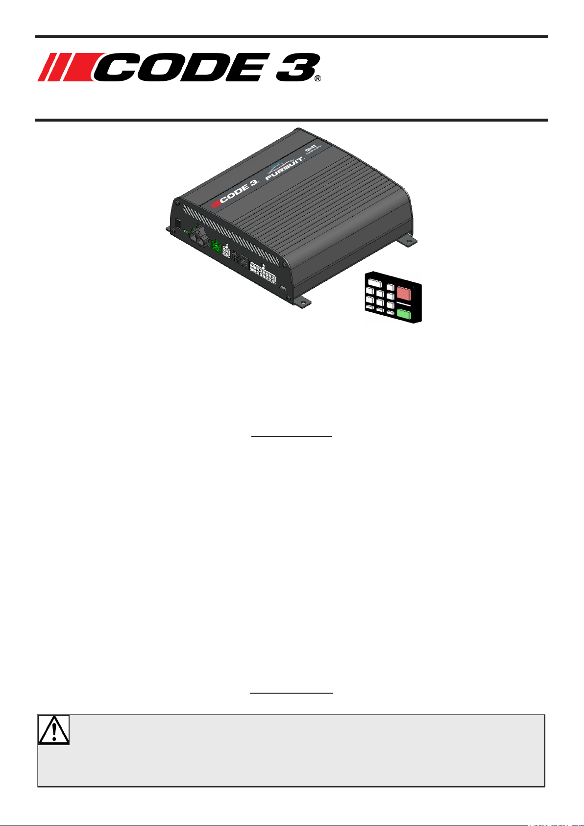
Pursuit Siren
Designed in Australia, the Code-3 Pursuit Siren sets a new benchmark in audible warning
systems. With two independent 100W speaker channels and multi-voltage operation, the
Pursuit Siren is ready for action on the full spectrum of emergency vehicles. Approved to
the highest standards in acoustics, EMC and reliability, the siren is fully network compatible
and integrates seamlessly with other network enabled products such as the Pursuit Lightbar
and Matrix Display, to provide complete vehicle warning systems with truly unique features.
SPECIFICATIONS
Input Voltage Range 10-30 VDC
Current Draw - Standby (Typ.) 10 mA
Current Draw (200W) 18A (12V) / 9A (24V)
Speaker Voltage 33Vrms
Dimensions (H x W x D mm) 65 x 121 x 37
Ambient Operating Temperature -30 to +65 °C
Features 8 congurable I/O
3 xed position inputs
Over-voltage, under-voltage, thermal shutdown
protection and reverse polarity protection (-36V)
Public Address Microphone with Adjustable Volume
Radio Rebroadcast Capability
Software Congurable with USB update.
Vehicle Horn Interface (HRT)
Output short-circuit protection
CERTIFICATIONS:
ECE R10, SAE J1849 (when paired with C3100 speaker), CISPR-25, RCM
`
WARNING!
Failure to install or use this product according to manufacturer’s recommendations may result
in property damage, serious bodily/personal injury, and/or death to you and those you are
seeking to protect!
Page 2
PURSUIT SIREN
Do not install and/or operate this safety product unless you have read and understand the
safety information contained in this manual.
1. Proper installation combined with operator training
in the use, care, and maintenance of emergency
warning devices are essential to ensure the safety
of you and those you are seeking to protect.
2. Exercise caution when working with live electrical
connections.
3. This product must be properly grounded.
Inadequate grounding and/or shorting of electrical
connections can cause high current arcing, which
can cause personal injury and/or severe vehicle
damage, including re.
4. Proper placement and installation are vital to the
performance of this warning device. Install this
product so that output performance of the system
is maximised and the controls are placed within
convenient reach of the operator so that s/he can
operate the system without losing eye contact with
the roadway.
5. It is the responsibility of the vehicle operator to
ensure during use that all features of this product
work correctly. In use, the vehicle operator should
ensure the projection of the warning signal is not
blocked by vehicle components (i.e., open trunks
or compartment doors), people, vehicles or other
obstructions.
6. The use of this or any other warning device
does not ensure all drivers can or will observe or
react to a warning signal. Never take the rightof-way for granted. It is your responsibility to be
sure you can proceed safely before entering an
intersection, driving against trac, responding at a
high rate of speed, or walking on or around trac
lanes.
7. This equipment is intended for use by authorized
personnel only. The user is responsible for
understanding and obeying all laws regarding
warning signal devices. Therefore, the user
should check all applicable city, state, and federal
laws and regulations. The manufacturer assumes
no liability for any loss resulting from the use of
this warning device.
8. Keep your attention on the road. Don’t try to
operate or focus on any device while you’re
driving.
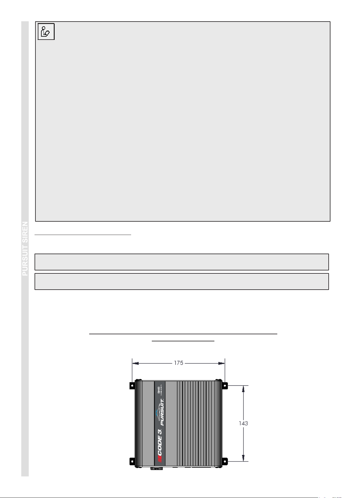
INSTALLATION & MOUNTING
Before installation, examine the equipment for transit damage. Do not use damaged or broken parts.
Important! This unit is a safety device and it must be connected to its own separate, fused power source to
assure its continued operation should any other electrical accessory fail.
Caution: When drilling into any vehicle surface, make sure the area is free from any electrical wires, fuel lines,
vehicle upholstery, etc. that could be damaged.
Before any installation work is carried out, plan where the various components will be mounted and what route
the wiring will take. The siren can be mounted by screwing it into any at surface using the 4 x supplied screws,
preferably with a drip loop so it is not possible for water to run down the cables into the unit.
Suggested mounting locations include the boot, under passenger seat or passenger footwell area.
THE SIREN IS NOT WATERPROOF, IT MUST BE MOUNTED WITHIN
THE VEHICLE CABIN.
920-0655-00 Rev B
Page 2 of 8
Page 3
PURSUIT SIREN
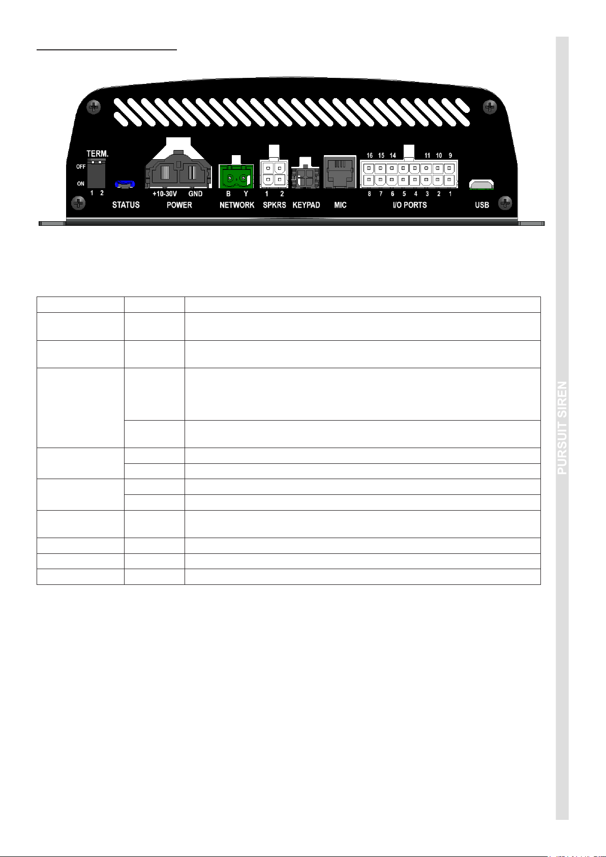
WIRING INSTRUCTIONS
Before proceeding with installation, plan all cable routing and wiring carefully.
PORT REF DESCRIPTION
TERM.
STATUS
POWER
NETWORK
SPKRS
KEYPAD
MIC Connect the microphone here.
I/O PORTS Refer wiring diagram.
USB Conguration and rmware updates via Software Graphical User Interface.
+10-30V
GND
B Connect the Blue wire from the HazCAN device(s).*
Y Connect the Yellow wire from the HazCAN device(s).*
1 Connect Speaker 1 here.
2 Connect Speaker 2 here (for 200W applications only).
Network termination setting. Default 1=ON; 2=OFF. For further details, refer
to Network Application Note.
The Status LEDs indicate various aspects of the current operation of the
siren. RED = Bootloader (programming mode / rmware update).
Connect to 4.5mm² (10 AWG) automotive wire to a fused power source,
using the shortest possible wire length. Fuses should be 15A for 100W
variants, and 25A for 200W variants. Do not connect this power wire until
all other connections have been made to the unit.
Connect to 4.5mm² (10 AWG) automotive wire to a good chassis ground
point or the battery negative terminal, using the shortest possible wire length.
Connect HazCAN compatible devices (via extension cable if required) to this
port (optional).
*Network cable requirements: Twisted pair, 30mm pitch Blue/Yellow. 0.25mm2 / 24AWG.
920-0655-00 Rev B
Page 3 of 8
Page 4

PURSUIT SIREN
1
1
2
2
3
3
4
4
5
5
6
6
7
7
8
8
D D
C C
B B
A A
DC
SM
NON DISCLO SURE AGREEMENT
THIS DRAWING AND THE DESIGN IT DISCLOSES ARE THE PRIVATE PROPERTY OF ECCO GROUP AND ARE ISSUED IN CONFIDENCE FOR
ENGINEERING INFORMATION ONLY. THE DRAWING AND/OR DESIGN MAY NOT BE USED, COPIED, REPRODUCED OR OTHERWISE
DISCLOSED IN PART OR AS A WHOLE TO OUTSIDERS OR USED FOR ANY OTHER PURPOSES WITHOUT THE PRIOR WRITTEN CONSENT OF
ECCO GROUP. THE DRAWING IS SUBJECT TO RECALL AT ANY TIME. YOUR POSSESSION OF THIS DOCUMENT CONSTITUTES
ACCEPTANCE OF THESE TERMS. © 20
18 ECCO GROUP.
Code-3 Australia | +61 (0) 3 6332 2400 | www.eccosafetygroup.com.au
APPROVAL S DATE
DESIGNER
ENG
2018-10-26
2018-10-26
2018-10-26Date Crea ted:
A3Sheet size:1 1Sheet of
C3-DNA
Project:
C3DNA SYSTEM GENERIC
Description:
A
Rev:
DNA-00001
Drawing #:
Variant:
[No Variations]
*SALES YYYY-MM-DD
Output
±In/Out
±Input
+In/Out
+Input
Sync (Legacy)
C3DNA-L
C3DNA-H
Power (10-30V)
Ground
Do Not Connect
C3-DNA CONNECTOR COLOUR KEY
HID: 500
25A
C1
HID: 400
25A
PURSUIT LIGHTBAR optional
HID: 300
White Flash OUTPUT
Alley Left OUTPUT
Park Light (+) INPUT
Sign Light OUTPUT
HRT (-) INPUT
Primary OUTPUT
C1
IO1
IO3
IO5
IO7
IN9
IN11
N/C
RAD
IO2
IO4
IO6
IO8
IN10
N/C
SYNC
RAD
1
2
3
4
5
6
7
816
15
14
13
12
11
10
9
Alley Right OUTPUT
Secondary OUTPUT
Takedown OUTPUT
Low Freq Enable (-) INPUT
Test Volume (-) INPUT
SLIC FUNCTIONS:
PRIMARY:
SIREN PRIMARY OUTPUT
SECONDARY:
SIREN SECONDARY OUTPUT
ALERT:
SIREN PRIMARY OUTPUT
SIREN SECONDARY OUTPUT
ACTIVATES THE FOLLOWING SIREN TONES:
CHANNEL 1 - WAIL
CHANNEL 2 - WAIL
PRESS ALERT AGAIN:
TOGGLES CHANNEL 1 BETWEEN WAIL AND YELP
MAN:
CHANNEL 1 - MANUAL TONE
CHANNEL 2 - MANUAL TONE
ALLEY LEFT:
SIREN ALLEY LEFT OUTPUT
ALLEY RIGHT:
SIREN ALLEY RIGHT OUTPUT
TAKEDOWN:
SIREN TAKEDOWN OUTPUT
LIGHT:
SIREN SIGN LIGHT OUTPUT
WAIL-YELP:
CHANNEL 1 - YELP
CHANNEL 2 - WAIL
SIREN-2:
CHANNEL 1 - YELP LF
CHANNEL 2 - YELP
HRT: LOW FREQUENCY NOT ENABLED
1 TAP - TONE CHANGE
HOLD
- AIRHORN
HRT: LOW FREQUENCY ENABLED
1 TAP - WHEN SIREN ACTIVE - LOW FREQUENCY BURST 8 SECONDS
HOLD - AIRHORN
CS82-00001
SLIC-00001
Optional
920-0655-00 Rev B
Page 4 of 8
Page 5

PURSUIT SIREN
TROUBLESHOOTING:
All products are thoroughly tested prior to shipment. However, should you encounter a problem during installation
or during the life of the product, follow the guide below for troubleshooting and repair information. If the problem
cannot be rectied using the solutions given below, additional information may be obtained from the manufacturer
– contact details are at the end of this document.
PROBLEM POSSIBLE CAUSE SOLUTION
Wires short circuit Check power and ground for short circuits
Fuse Blows ¹
Faulty unit
If fuse continues to blow after checking the
wiring replace the product
Unstable operation HazCAN wiring fault
¹ Note: Always replace the fuse with the same value as shown on the wiring diagram
Check wire colours match the label positions on
siren unit
920-0655-00 Rev B
Page 5 of 8
Page 6

PURSUIT SIREN
NOTES
920-0655-00 Rev B
Page 6 of 8
Page 7

PURSUIT SIREN
NOTES
920-0655-00 Rev B
Page 7 of 8
Page 8

Manufacturer Limited Warranty and Limitation of Liability:
Manufacturer warrants that on the date of purchase this product will conform to Manufacturer’s specications for this product
(which are available from the Manufacturer upon request), and Manufacturer further warrants that this product is free from
defects in materials and workmanship. This Limited Warranty extends for twelve (12) months from the date of purchase. Other
warranties may apply, call Manufacturer for details. Manufacturer will, at its discretion, repair or replace any product found by
the Manufacturer to be defective and subject to this Limited Warranty.
DAMAGE TO PARTS OR PRODUCTS RESULTING FROM TAMPERING, ACCIDENT, ABUSE, MISUSE, NEGLIGENCE,
UNAPPROVED MODIFICATIONS, FIRE OR OTHER HAZARD; IMPROPER INSTALLATION OR OPERATION; OR NOT
BEING MAINTAINED IN ACCORDANCE WITH THE MAINTENANCE PROCEDURES SET FORTH IN MANUFACTURER’S
INSTALLATION AND OPERATING INSTRUCTIONS VOIDS THIS LIMITED WARRANTY.
ORAL STATEMENTS OR REPRESENTATIONS ABOUT THE PRODUCT WHICH MAY HAVE BEEN MADE BY
SALESPEOPLE, DEALERS, AGENTS OR OTHER MANUFACTURER’S REPRESENTATIVES DO NOT CONSTITUTE
WARRANTIES. THIS LIMITED WARRANTY MAY NOT BE AMENDED, MODIFIED, OR ENLARGED EXCEPT BY A
WRITTEN AGREEMENT SIGNED BY AN AUTHORIZED OFFICIAL OF MANUFACTURER WHICH EXPRESSLY REFERS
TO THIS LIMITED WARRANTY.
Exclusion of Other Warranties: MANUFACTURER MAKES NO OTHER WARRANTIES, EXPRESS OR IMPLIED.
THE IMPLIED WARRANTIES FOR MERCHANTABILITY OR FITNESS FOR A PARTICULAR PURPOSE ARE HEREBY
EXCLUDED AND SHALL NOT APPLY TO THE PRODUCT. BUYER’S SOLE AND EXCLUSIVE REMEDY IN CONTRACT,
TORT, OR UNDER ANY OTHER THEORY AGAINST MANUFACTURER REGARDING THE PRODUCT AND ITS USE
SHALL BE THE REPLACEMENT OR REPAIR OF THE PRODUCT AS DESCRIBED ABOVE.
Limitation of Liability: IN THE EVENT OF LIABILITY FOR DAMAGES ARISING OUT OF THIS LIMITED WARRANTY OR
ANY OTHER CLAIM RELATED TO THE MANUFACTURER’S PRODUCTS, MANUFACTURER’S LIABILITY FOR DAMAGES
SHALL BE LIMITED TO THE AMOUNT PAID FOR THE PRODUCT AT THE TIME OF THE ORIGINAL PURCHASE. IN
NO EVENT SHALL MANUFACTURER BE LIABLE FOR LOST PROFITS, THE COST OF SUBSTITUTE EQUIPMENT OR
LABOR, PROPERTY DAMAGE, OR OTHER SPECIAL, CONSEQUENTIAL, OR INCIDENTAL DAMAGES BASED UPON
ANY CLAIM FOR BREACH OF CONTRACT, IMPROPER INSTALLATION, NEGLIGENCE, OR OTHER CLAIM, EVEN IF
MANUFACTURER OR A MANUFACTURER’S REPRESENTATIVE HAS BEEN ADVISED OF THE POSSIBILITY OF SUCH
DAMAGES. MANUFACTURER SHALL HAVE NO FURTHER OBLIGATION OR LIABILITY WITH RESPECT TO THE
PRODUCT OR ITS SALE, OPERATION AND USE, AND MANUFACTURER NEITHER ASSUMES NOR AUTHORIZES THE
ASSUMPTION OF ANY OTHER OBLIGATION OR LIABILITY IN CONNECTION WITH SUCH PRODUCT.
This Limited Warranty denes specic legal rights. You may have other legal rights which vary from state to state. Some states
do not allow the exclusion or limitation of incidental or consequential damages.
439 Boundary Road,
Truganina,
Victoria, 3029
Australia
Customer Service
1800 815 000 (Australia only)
+61 3 8336 0680 (International)
www.eccosafetygroup.com.au
920-0655-00 Rev B
© 2017 CODE 3 INC.
Page 8 of 8
 Loading...