

Page 1

Installation and Operation Instructions
Pursuit Lightbar
Introduction
The Pursuit™ Lightbar is a versatile, powerful, high output
warning device suitable for a range of vehicle types and
duties. There are numerous options and lengths available.
The lightbar can either be mounted permanently to the
vehicle or mounted using the vehicle roof gutters. It also
utilizes individual top lenses for easy internal access with
a provision to disconnect the lightbar cable to allow easy
removal of the lightbar.
Contents
Introduction 1
Installation & Mounting 2
Wiring Instructions 2,3
Junction Box Instructions 3,4,5
Warning Signal Modules 6
Controller Features and Functions 6,7
Exploded View 7
The unique shape of the Pursuit Lightbar ensures a sleek,
low prole body hugging t for many vehicle applications.
In addition to the long, maintenance free service life
and low current draw benets of LED technology, the
dual deck Pursuit also supports additional auxiliary
lighting options. Featuring an aluminium chassis and
clear, weatherproof, polycarbonate lenses along with
Replacement Parts 8
Maintenance 9
Troubleshooting 9
Notes 10,11
Warranty 12
encapsulated electronic control modules, the lightbar is
strong, durable and protected against the environment.
IMPORTANT! Read all instructions before installing and using. Installer: This manual must be delivered to the end user.
WARNING!
Failure to install or use this product according to manufacturers recommendations may result in property damage, serious injury,
and/or death to those you are seeking to protect!
Do not install and/or operate this safety product unless you have read and understand the safety information contained in this manual.
1. Proper installation combined with operator training in the use, care, and maintenance of emergency warning devices are essential to
ensure the safety of emergency personnel and the public.
2. Emergency warning devices often require high electrical voltages and/or currents. Exercise caution when working with live electrical
connections.
3. This product must be properly grounded. Inadequate grounding and/or shorting of electrical connections can cause high current arcing,
which can cause personal injury and/or severe vehicle damage, including re.
4. Proper placement and installation is vital to the performance of this warning device. Install this product so that output performance of the
system is maximized and the controls are placed within convenient reach of the operator so that s/he can operate the system without losing
eye contact with the roadway.
5. It is the responsibility of the vehicle operator to ensure daily that all features of this product work correctly. In use, the vehicle operator
should ensure the projection of the warning signal is not blocked by vehicle components (i.e., open trunks or compartment doors), people,
vehicles or other obstructions.
6. The use of this or any other warning device does not ensure all drivers can or will observe or react to an emergency warning signal. Never
take the right-of-way for granted. It is your responsibility to be sure you can proceed safely before entering an intersection, drive against
trafc, respond at a high rate of speed, or walk on or around trafc lanes.
7. This equipment is intended for use by authorized personnel only. The user is responsible for understanding and obeying all laws regarding
emergency warning devices. Therefore, the user should check all applicable city, state, and federal laws and regulations. The manufacturer
assumes no liability for any loss resulting from the use of this warning device.
920-0505-00 Rev. B
Page 1 of 12
Page 2
Installation and Mounting
Unpacking and Pre-installation Inspection
Carefully remove the light bar and place it on a at surface, taking care not to scratch the lenses or damage the cable coming out of the bottom. Examine the unit for transit damage, broken light heads, etc. Report any damage to the carrier and
keep the shipping carton.
Standard light bars are built to operate on 12volt and 24volt D.C. negative ground (earth) vehicles. If you have an electrical
system other than 12volt or 24volt D.C. negative ground (earth), and have not ordered a specially wired light bar, contact the
factory for instructions.
Test the unit before installation. To test, connect the Junction Box to the lightbar per the Network Junction Box Instruc-
tions section of this manual and touch the black wire to the ground (earth) and the red wire to +12volt or +24volt D.C. (an
automotive battery is preferable for this test). Then touch each of the control wires to power and check for proper operation.
If problems occur at this point, please contact the factory.
Mounting the Lightbar
All mounting hardware is packed in a small box or bag inside the main carton. Four standard kits are available: (1) Hook-On
Type, (1) Tow and Recovery and (2) Permanent Types. NOTE: Hook-on mounting for "gutterless" type vehicles will require a
special hook for mounting. Several special application hooks are available. Contact the factory for details. Refer to the instructions included with the mounting kit for installation.
CAUTION!
When drilling into any vehicle surface, make sure the area is free from any electrical wires, fuel
lines, vehicle upholstery, etc. that could be damaged.
Quick Lightbar Removal
The Pursuit lightbar has been designed with a unique cable access hole enabling the lightbar to be removed without uninstalling the lightbar cable.
1. Remove power to the lightbar/junction box. Failure to do this may damage the lightbar.
2. Remove upper lens set as described in “Lens removal and Installation” in the Maintenance section of this manual.
3. Undo the cable gland nut from the plastic housing. (The large plastic nut inside the lightbar)
4. Unplug the data connector from the LED controller.
5. Using a No.2 point Phillips screwdriver, remove the screw grounding the external harness to the chassis, and the posi-
tive feed to the LED controller.
6. At this point the cable can be pulled from the opening in the plastic housing and the lightbar removed from the vehicle.
Feed the ring terminals through the plastic nut rst then the data connector and do this for the plastic housing also.
7. When reconnecting the lightbar, connect the wiring harnesses and cable gland as originally installed.
Wiring Instructions
Before attempting to connect the lightbar wiring harness, refer to the Network Junction Box Instructions section of this
manual.
1. After the light bar has been mounted, route the wiring harness into the vehicle to the intended network junction box location.
2. Route wires from the vehicle positive (preferrably the battery) to the switch panel in the cab. The vehicle negative should
be direct from the battery negative terminal also. Use suitable high-temperature wire if it passes through the engine compartment. Install a suitable fuse as close to the point of tapped power as possible.
3. See Network Junction Box Instructions for connecting the wires from the lightbar cable and the vehicle to the junction
box. This section has instructions for connecting the input wires from the junction box to the control circuits applicable for
each option. Leave unused wires unconnected and insulated.
4. Use cable ties and grommets to secure and protect all cables and wires.
Important! This unit is a safety device and it must be connected to its own separate, fused power point to assure its
continued operation should any other electrical accessory fail. Do not wire in parallel with any other accessory.
CAUTION!
920-0505-00 Rev. B
Disconnect the battery before wiring up the light bar, to prevent accidental shorting, arcing and/
or electrical shock.
Page 2 of 12
Page 3
Notes:
1. Larger wires and tight connections will provide longer service life for components. For high current wires it
is highly recommended that terminal blocks or soldered connections be used with shrink tubing to protect
the connections. Do not use insulation displacement connectors (e.g., 3M Scotchlock type connectors).
2. Route wiring using grommets and sealant when passing through compartment walls. Minimize the
number of splices to reduce voltage drop. High ambient temperatures (e.g., under-hood) will signicantly
reduce the current carrying capacity of wires, fuses, and circuit breakers. All wiring should conform to the
minimum wire size and other recommendations of the manufacturer and be protected from moving parts
and hot surfaces. Looms, grommets, cable ties, and similar installation hardware should be used to anchor
and protect all wiring.
3. Fuses or circuit breakers should be located as close to the power takeoff points as possible and properly
sized to protect the wiring and devices.
4. Particular attention should be paid to the location and method of making electrical connections and splices
to protect these points from corrosion and loss of conductivity.
5. Ground termination should only be made to substantial chassis components, preferably directly to the
vehicle battery.
6. Circuit breakers are very sensitive to high temperatures and will “false trip” when mounted in hot
environments or operated close to their capacity.
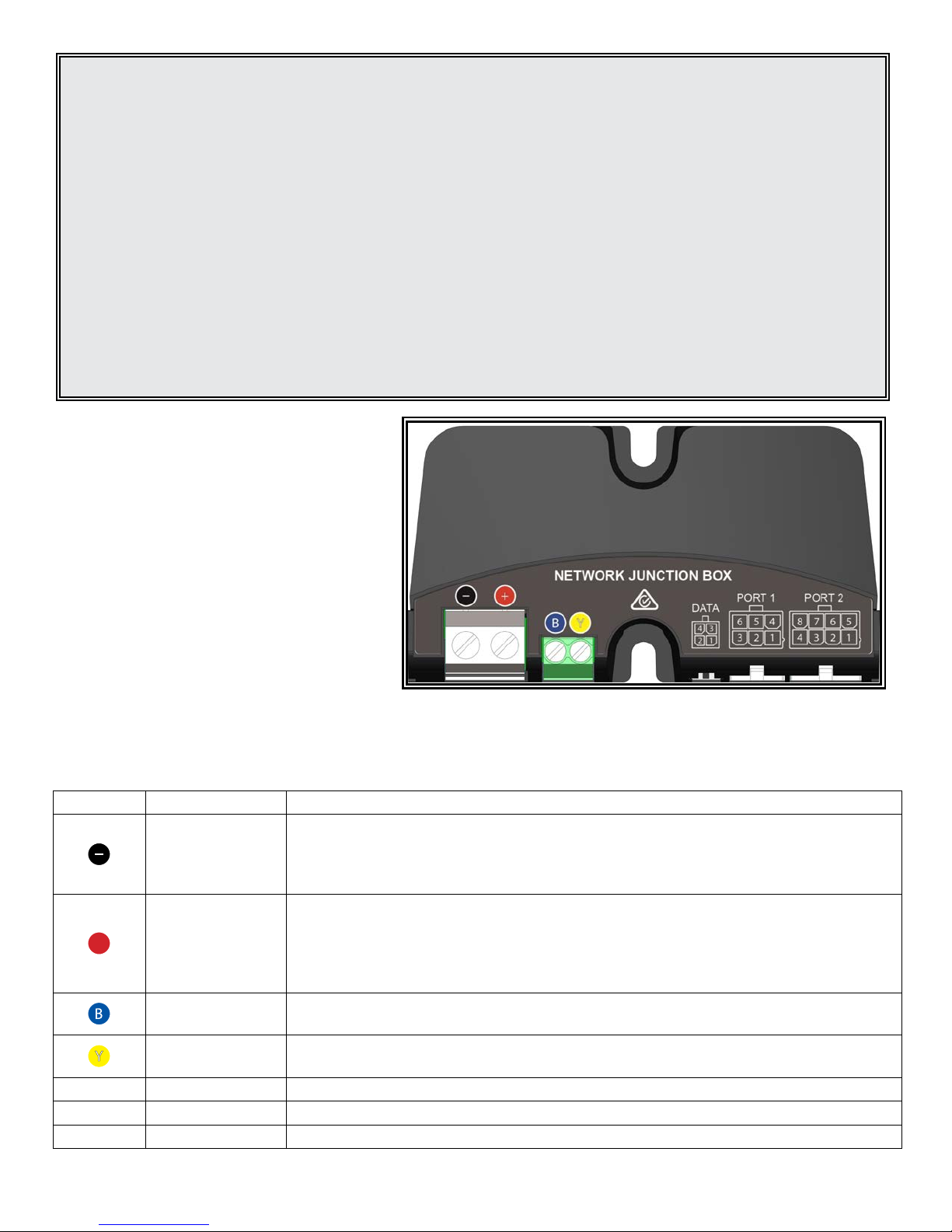
Network Junction Box Instructions
The Pursuit lightbar is controlled by the Code 3
Network Junction Box designed for multi-voltage
operation. Before proceeding with installation,
plan all cable routing and wiring carefully.
The Junction box can be mounted by screwing it
into any at surface using the 2 x
supplied screws,
preferably with a drip loop so it is not possible for
water to run down the cables into the unit.
THE JUNCTION BOX IS NOT WATERPROOF, IT
MUST BE MOUNTED WITHIN THE VEHICLE CABIN.
Specications
Input Voltage Range 10-30 VDC
Current Draw - Standby (Typ.) 14 mA
Ambient Operating Temperature -20 to +65 °C
REF PORT DESCRIPTION
Connect the Black ground wire from the Pursuit lightbar’s six conductor cable and
Black screw
terminal
vehicle ground connection, insert both into the screw terminal and tighten. Use a good
chassis ground point or the battery negative terminal, using the shortest possible wire
length with a 10 AWG (4.5mm²) automotive wire.
Connect the Red wire from the Pursuit lightbar’s six conductor cable and vehicle power
+
Red screw
terminal
connection, insert both into the screw terminal and tighten. Use a 10 AWG (4.5mm²)
automotive wire from an external fused or circuit breakered source, using the shortest
possible wire length. The recommended external fuse size is 30A. Do not connect this
power wire until all other connections have been made to the unit.
Blue screw
terminal
Yellow screw
terminal
Connect the Blue wire from the Pursuit lightbar’s cable. This wire connects directly to
the lightbar’s internal controller and should never be connected to power.
Connect the Yellow wire from the Pursuit lightbar’s cable. This wire connects directly
to the lightbar’s internal controller and should never be connected to power.
DATA 4 Way Socket Connect the C3Pro Conguration Programmer to this port when programming.
PORT 1 6 Way Socket See tables below for wire colors and functions.
PORT 2 8 Way Socket See tables below for wire colors and functions.
920-0505-00 Rev. B
Page 3 of 12
Page 4
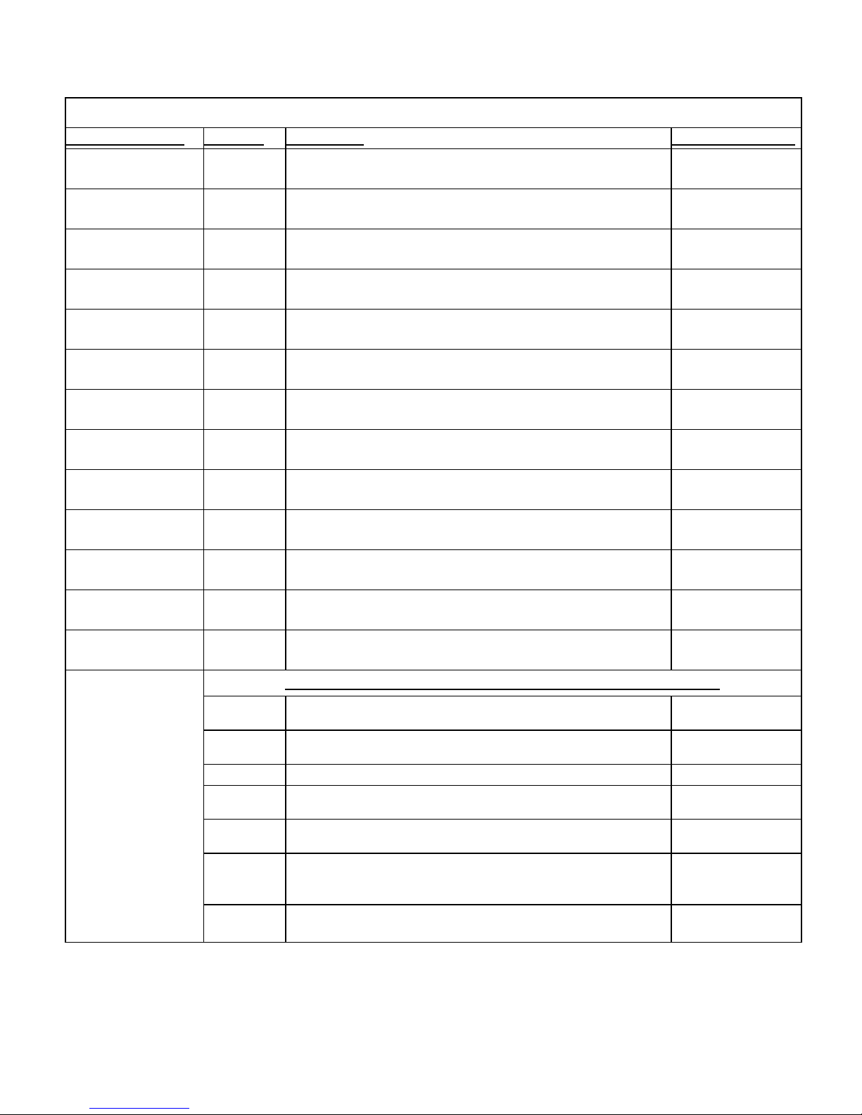
Input Wiring Functions for Network Junction Box
36 Inch and Shorter Pursuit Lightbars
Input (Wire Color) Function Description Flash Pattern/Rate
Green/Black Level 1 Level 1 Emergency Mode. Sweep Rev
White/Black Level 2 Level 2 Emergency Mode. Dual End Rotate
Red/Black Level 3 Level 3 Emergency Mode. Pursuit
Orange/Black Takedown Forward facing lower light heads steady burn. Steady
Yellow Left Alley Left facing lower light heads steady burn. Steady
Purple Right Alley Right facing lower light heads steady burn. Steady
Grey
Brown
TD/Alley
Flash
Driver Side
Cut
Forward, Left, and Right lower light heads ash. Single 150
Triggers Driver Side Corners and Alley Positions to turn off for
8 seconds.
Not Available
Blue/Black Rear Cut Triggers all rear facing and rear corners to turn off. Not Available
Pink Front Cut Triggers all front facing and front corners to turn off. Not Available
Green Cruise
Blue Dim
Orange
Arrowstik
Flash
All upper corner light heads will steady burn in a dimmed
state.
Dim can be applied to any feature and pattern except for TD
and Alley.
Cruise Low
Dim Low
Rear lower light heads ash. Single 150
Additional functions not included as part of default conguration
Alley Flash Left and Right lower light heads ash. Single 150
TD Flash Forward lower light heads ash. Single 150
Aux Customer Dened
Left Arrow Rear facing lower light heads illuminate in the left direction. Building Fast
Right Arrow Rear facing lower light heads illuminate in the right direction. Building Fast
Center Out
California
Steady
Rear facing lower light heads illuminate from the center then
outward direction.
Light head steady burns for California T13 Compliance. CA Steady
Any of the wires above not used to control the lightbar should be capped or otherwise insulated from
accidental contact with power sources.
920-0505-00 Rev. B
Building Fast
Page 4 of 12
Page 5

Input Wiring Functions for Network Junction Box Cont.
42 Inch and Longer Pursuit Lightbars
Input (Wire Color) Function Description
Flash Pattern/Rate
Green/Black Level 1 Level 1 Emergency Mode. Sweep Rev
White/Black Level 2 Level 2 Emergency Mode. Dual End Rotate
Red/Black Level 3 Level 3 Emergency Mode. Pursuit
Orange/Black Take Down Forward facing lower light heads steady burn. Steady
Yellow Left Alley Left facing lower light heads steady burn. Steady
Purple Right Alley Right facing lower light heads steady burn. Steady
Grey
Brown
TD/Alley
Flash
Driver Side
Cut
Forward, Left, and Right lower light heads ash. Single 150
Triggers Driver Side Corners and Alley Positions to turn off for
8 seconds.
Not Available
Blue/Black Rear Cut Triggers all rear facing and rear corners to turn off. Not Available
Green Cruise All upper corner light heads will steady burn in a dimmed state. Cruise Low
Blue Dim
Pink + Orange Center Out
Dim can be applied to any feature and pattern except for TD
and Alley.
Rear facing lower light heads illuminate from the center then
outward direction.
Dim Low
Building Fast
Orange Right Arrow Rear facing lower light heads illuminate in the right direction. Building Fast
Pink Left Arrow Rear facing lower light heads illuminate in the left direction. Building Fast
Additional functions not included as part of default conguration
Front Cut Triggers all front facing and front corners to turn off. Not Available
Alley Flash Left and Right lower light heads ash. Single 150
TD Flash Forward lower light heads ash. Single 150
Arrowstik
Flash
Rear lower light heads ash. Single 150
Aux Customer Dened
California
Steady
Light head steady burns for California T13 Compliance. CA Steady
Any of the wires above not used to control the lightbar should be capped or otherwise insulated from
accidental contact with power sources.
920-0505-00 Rev. B
Page 5 of 12
Page 6

Warning Signal Modules
There are many different types of light heads producing various warning signals in the lightbar as explained below.
Note: LED modules are not user serviceable. All retaining screws to be torqued to 18 IN-LB (2.0 N-M).
Upper Deck Modules
Designed for an uncompromised warning signal, the
upper level LED modules combine maximum emitting
surface area with a very high output LED optical
system to produce an effective output at all angles
around the vehicle. These multi-voltage units operate
from 10V to 30V using 100% solid-state electronics and
LEDs rated to 100,000 hours of operation.
Lower Level LED Modules
Developed primarily to provide practical illumination
over a broad area around the vehicle, the lower level
cool-white LED modules pack high output into a very
slimline optic. Options range from individual alley or
takedown lights up to full 360° scene coverage, without
impacting on upper level lightbar lens or LED color
requirements. They can also be congured to ash in
conjunction with the upper level warning patterns. In
the amber version, the lower level can be congured
as a trafc advisor, with a high resolution switching
function for an improved visual effect.
Sign Light Module
Mounted inside the lightbar and fully protected from
weathering, the LED sign light is an enclosed module
carefully specied to provide homogenous backlighting
of the sign area while minimizing stray light. The
overlaid text is available in plain white text with black,
blue or amber background, or colored text with white
background. Signs are also available in mirrored text.
Lightbar Controller
The Lightbar Controller can control up to 32 separate light
heads, each of which can be congured to perform any
supported lightbar function. Multiple controllers can work
together in a lightbar to provide virtually unlimited lighting
outputs. Operating on the HazCAN serial bus, the Controller
is also able to provide power and data to the M5 Message
Display and other compatible devices while requiring only
a compact 4-wire harness out of the lightbar, regardless
of the number of functions. The Controller electronics are
encapsulated in high-temperature silicon potting material
and housed in a rugged cast aluminium case for maximum
durability. Lightbar chassis temperatures and ambient lighting
levels are monitored by the Controller in order to maximize
lighting output in a safe and controlled manner, over a wide
range of environmental conditions throughout the life of the
product.
CAUTION!
920-0505-00 Rev. B
Lightbar Controller outputs are only compatible with Pursuit LED Modules. The warranty will be
void if unsupported products are connected to the controller.
Page 6 of 12
Page 7

Auto Dimming (when congured in C3Pro
Conguration Programmer)
The lightbar is capable of automatically dimming
the highly intense warning signals produced by
the light heads. Onboard ambient light sensors
detect the level of daylight present, and can dim
the warning signals to a predetermined output.
This reduces the chance of dazzling other road
users, creating a safer environment at night.
Default settings have this feature disabled.
Please consult the C3 Pro™ Interface
Software (Quick Install) Manual for more
programming features and settings.
Exploded View of Lightbar Assembly
See the following page for a list of the referenced
replacement parts as indicated by the balloon
numbers.
12
15
3
8 9
5 6
14
920-0505-00 Rev. B
2
10
4
11
1
13
7
Page 7 of 12
Page 8

Replacement Parts and Accessories (See previous page for exploded view of lightbar)
CAUTION!
Description Part Number
Lenses Upper
1. Upper Outboard Lens - Red 250-0340-04
Upper Outboard Lens - Blue 250-0340-22
Upper Outboard Lens - Clear 250-0340-03
Upper Outboard Lens - Amber 250-0340-02
2. Upper Center Lens Short - Red 250-0341-04
Upper Center Lens Short - Blue 250-0341-22
Upper Center Lens Short - Clear 250-0341-03
Upper Center Lens Short - Amber 250-0341-02
3. Upper Center Lens Long - Red 250-0342-04
Upper Center Lens Long - Blue 250-0342-22
Upper Center Lens Long - Clear 250-0342-03
Upper Center Lens Long - Amber 250-0342-02
Inner Panels
4. Outboard Inner Panel 220-0602-00
5. Center Long Inner Panel 220-0603-00
6. Center Short Inner Panel 220-0604-00
Lenses Lower
7. Lower Outboard Lens - (Clear only) 250-0343-03
8. Lower Center Short Lens - (Clear only) 250-0344-03
9. Lower Center Long Lens - (Clear only) 250-0345-03
LED Modules Upper
10. Upper Level Light Head - Red 155-0420-03
Upper Level Light Head - Blue 155-0420-01
Upper Level Light Head - White 155-0420-02
LED Modules Lower
11. Lower Level Light Head - White 155-0421-02
Lower Level Light Head - Red 155-0421-04
Lower Level Light Head - Blue 155-0421-22
Lower Level Light Head - Amber 155-0421-00
Sign Head
12. Illuminated sign 155-0424-00
Light Head Mtg Brkts
13. Outboard end bracket 220-0612-00
14. Lower light head bracket 220-0598-00
Controller
15. M5-LED32 controller 155-0419-00
Screws
Lens screw (M5 x 30mm socket cap - not shown) 323-0050-00
Internal screw (M5 x 10mm Phillips head - not shown) 323-0051-00
920-0505-00 Rev. B
When replacing LED modules it is important to note the output from the controller for the module
being replaced, because damage can occur from incorrect module conguration. Details regarding
conguration of a specic lightbar can be obtained from the manufacturer.
Page 8 of 12
Page 9

Maintenance
Occasional cleaning of the lenses will ensure optimum light output. Take care when cleaning lenses, although very
impact resistant, polycarbonate scratches easily. Clean the lens and base with soap and water or a lens polish
using a microber or other lint free soft cloth. Do not use solvents as they may damage the polycarbonate.
Lens Removal and Installation
1. Identify the lens(es) to be removed - not all lenses need to be removed to access the internal components.
2. Unfasten the retaining screws from the lens(es) of the lightbar - the screws can be left captive in the lens.
3. Carefully lift the lens off the seal – choose a suitable location to temporarily store the lens so as to not scratch
the surface.
4. When reinstalling, gently apply pressure around the upper lens taking care not to damage the seal around the
lower lens set. Retorque the retaining screws to 18 IN-LB (2.0 N-M).
Troubleshooting
All products are thoroughly tested prior to shipment. However, should you encounter a problem during installation
or during the life of the product, follow the guide below for troubleshooting and repair information. If the problem
cannot be rectied using the solutions given below, additional information may be obtained from the manufacturer.
Contact details are at the end of this document.
Lightbar Issues
PROBLEM POSSIBLE CAUSE SOLUTION
Lightbar does not function Poor power or ground
Check power and ground connections.
connection
Blown fuse Check wiring, replace fuse
One LED head does not
ash, but corresponding
indicator LED on control
module does ash.
Open circuit wiring from
control module to LED head
Poor ground connection at
Connect a known-good LED head to the
problem output to ensure the control module is
working correctly. Repair or replace.
Tighten or replace mounting screw.
LED head
Failed LED head Replace LED head
One LED head does not
ash, and corresponding
Wrong ash conguration Use C3Pro Conguration Programmer to correct
Failed control module Replace control module
indicator LED on control
module does not ash when
appropriate pattern selected.
Incorrect ash patterns Wrong ash conguration Use C3Pro Conguration Programmer to correct
Control Box Issues
PROBLEM POSSIBLE CAUSE SOLUTION
Fuse Blows ¹ Wires short circuit Check power and ground for short circuits
Faulty unit
Unstable operation Wiring fault Check that wire colors match the label positions
Output on Junction box is
not working
Note: Always replace the fuse with the same value as removed
¹
920-0505-00 Rev. B
Junction box fuse blown
(excessive load)
If fuse continues to blow after checking the
wiring replace the product
on Junction Box
Replace the Junction Box
Page 9 of 12
Page 10

Notes
920-0505-00 Rev. B
Page 10 of 12
Page 11

Notes
920-0505-00 Rev. B
Page 11 of 12
Page 12

Manufacturer Limited Warranty Policy:
Manufacturer warrants that on the date of purchase this product will conform to Manufacturer’s specications for this product (which are available from the Manufacturer upon request). This Limited Warranty extends for Sixty (60) months from the date of purchase.
DAMAGE TO PARTS OR PRODUCTS RESULTING FROM TAMPERING, ACCIDENT, ABUSE, MISUSE, NEGLIGENCE, UNAPPROVED MODIFICATIONS, FIRE OR OTHER HAZARD; IMPROPER INSTALLATION OR OPERATION; OR NOT BEING MAINTAINED IN ACCORDANCE WITH THE
MAINTENANCE PROCEDURES SET FORTH IN MANUFACTURER’S INSTALLATION AND OPERATING INSTRUCTIONS VOIDS THIS LIMITED WARRANTY.
Exclusion of Other Warranties:
MANUFACTURER MAKES NO OTHER WARRANTIES, EXPRESS OR IMPLIED. THE IMPLIED WARRANTIES FOR MERCHANTABILITY, QUALITY
OR FITNESS FOR A PARTICULAR PURPOSE, OR ARISING FROM A COURSE OF DEALING, USAGE OR TRADE PRACTICE ARE HEREBY EXCLUDED AND SHALL NOT APPLY TO THE PRODUCT AND ARE HEREBY DISCLAIMED, EXCEPT TO THE EXTENT PROHIBITED BY APPLICABLE
LAW. ORAL STATEMENTS OR REPRESENTATIONS ABOUT THE PRODUCT DO NOT CONSTITUTE WARRANTIES.
Remedies and Limitation of Liability:
MANUFACTURER’S SOLE LIABILITY AND BUYER’S EXCLUSIVE REMEDY IN CONTRACT, TORT (INCLUDING NEGLIGENCE), OR UNDER ANY
OTHER THEORY AGAINST MANUFACTURER REGARDING THE PRODUCT AND ITS USE SHALL BE, AT MANUFACTURER’S DISCRETION, THE
REPLACEMENT OR REPAIR OF THE PRODUCT, OR THE REFUND OF THE PURCHASE PRICE PAID BY BUYER FOR NON-CONFORMING PRODUCT. IN NO EVENT SHALL MANUFACTURER’S LIABILITY ARISING OUT OF THIS LIMITED WARRANTY OR ANY OTHER CLAIM RELATED TO
THE MANUFACTURER’S PRODUCTS EXCEED THE AMOUNT PAID FOR THE PRODUCT BY BUYER AT THE TIME OF THE ORIGINAL PURCHASE.
IN NO EVENT SHALL MANUFACTURER BE LIABLE FOR LOST PROFITS, THE COST OF SUBSTITUTE EQUIPMENT OR LABOR, PROPERTY
DAMAGE, OR OTHER SPECIAL, CONSEQUENTIAL, OR INCIDENTAL DAMAGES BASED UPON ANY CLAIM FOR BREACH OF CONTRACT, IMPROPER INSTALLATION, NEGLIGENCE, OR OTHER CLAIM, EVEN IF MANUFACTURER OR A MANUFACTURER’S REPRESENTATIVE HAS BEEN
ADVISED OF THE POSSIBILITY OF SUCH DAMAGES. MANUFACTURER SHALL HAVE NO FURTHER OBLIGATION OR LIABILITY WITH RESPECT
TO THE PRODUCT OR ITS SALE, OPERATION AND USE, AND MANUFACTURER NEITHER ASSUMES NOR AUTHORIZES THE ASSUMPTION OF
ANY OTHER OBLIGATION OR LIABILITY IN CONNECTION WITH SUCH PRODUCT.
This Limited Warranty denes specic legal rights. You may have other legal rights which vary from jurisdiction to jurisdiction. Some jurisdictions do not allow the exclusion or limitation of incidental or consequential damages.
Product Returns:
If a product must be returned for repair or replacement*, please contact our factory to obtain a Return Goods Authorization Number (RGA number)
before you ship the product to Code 3®, Inc. Write the RGA number clearly on the package near the mailing label. Be sure you use sufcient
packing materials to avoid damage to the product being returned while in transit.
*Code 3®, Inc. reserves the right to repair or replace at its discretion. Code 3®, Inc. assumes no responsibility or liability for expenses incurred for the removal and /or reinstallation of products requiring service and/or repair.; nor for the packaging, handling,
and shipping: nor for the handling of products returned to sender after the service has been rendered.
10986 North Warson Road
St. Louis, MO 63114
Technical Service:
(314) 996-2800
c3_tech_support@code3esg.com
www.code3esg.com
A Division of ESG | www.eccogroup.com
920-0505-00 Rev. B
Page 12 of 12
 Loading...