

Page 1
12 OUTPUT LED FLASHER MULTI-PATTERN
ELECTRICAL SPECIFICATION
PSELEDF12
Input Voltage Range +10 Vdc to +16 Vdc
Output Drive Current 3 Amps per Output
Operating Temperature -40 C to +85 C
Flash Patterns Quint, Quad, Triple, Double,
180 fpm Alternating Single,
120 fpm Alternating Single,
120 fpm Simultaneous Single,
90 fpm Alternating Single,
90 fpm Simultaneous Single,
75 fpm Alternating Single,
75 fpm Simultaneous Single,
Cycle Flash
Sweep (Lightbar version only)
Fast Random
Output Drive Method Low-side switched
Pattern Control Method 1 Serial Programming
input, 3 Progressive Operation
mode inputs, Front & Rear
Cutoff inputs
Standby Current <10mA @ 12.8 Vdc
Reverse Polarity Protection Yes
Short Circuit Protection Yes
Thermal Protection Yes
MECHANICAL SPECIFICATIONS
Weather resistance Potted to protect circuitry, but not
waterproof
Dimensions 6.0" x 3.6" x .75"
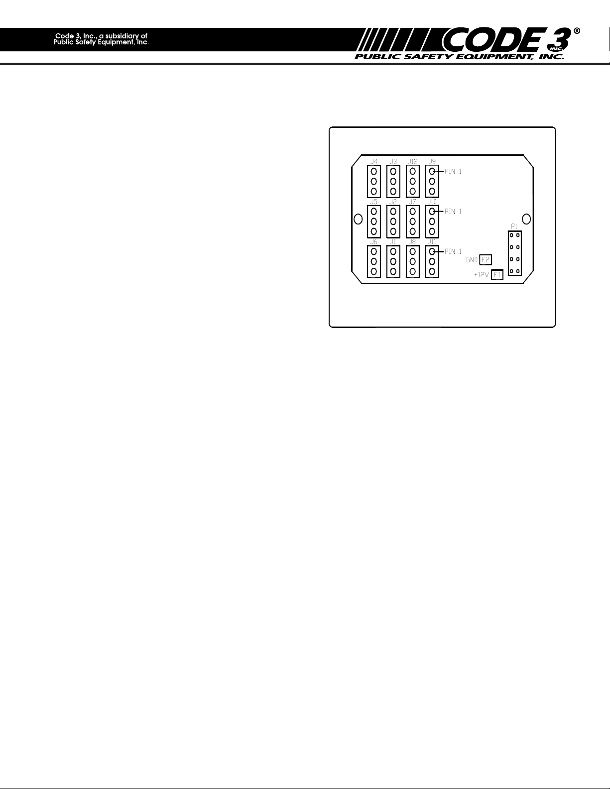
Figure1
WARNING
This Flasher is NOT waterproof!! This unit must
be installed in a location protected from the
environment.
The device is designed to flash Code 3, Inc. 12 volt
LED-EX Lights up to 3 amps load per output. DO NOT
connect more than a 3 amp load(two single LED-EX
equivalent) to the output. Doing so will shut the unit
down to prevent damage to the Flasher.
WARNING
This device is intended for use with LED Lights ONLY!! Use of this product on an Incandescent, Halogen or
any light source other than LED's may damage the unit and void the warranty.
The use of this or any warning device does not insure that all drivers can or will observe or react to an
emergency warning signal. Never take the right-of-way for granted. It is your responsibility to be sure you
can proceed safely before entering an intersection, driving against traffic, responding at a high rate of
speed, or walking on or around traffic lanes.
The effectiveness of this warning device is highly dependent upon correct mounting and wiring. Read and
follow the manufacturer's instructions before installing or using this device. The vehicle operator should
insure daily that all features of the device operate correctly. In use, the vehicle operator should insure the
projection of the warning signal is not blocked by vehicle components(i.e., open trunks or compartment
doors), people, vehicles, or other obstructions. This equipment is intended for use by authorized personnel
only. It is the user's responsibility to understand and obey all laws reguarding emergency warning devices.
The user should check all applicable city, state and federal laws and regulations.
Code 3, Inc., assumes no liability for any loss resulting from the use of this warning device. Proper
installation is vital to the performance of this warning device and the safe operation of the emergency
vehicle. It is important to recognize that the operator of the emergency vehicle is under psychological and
physiological stress caused by the emergenct situation. The warning device should be installed in such a
manner as to A) Not reduce the output performance of the system, B) Place the controls within convenient
reach of the operator so that he can operate the system without losing eye contact with the roadway.
Emergency warning devices often require high electrical voltages and/or currents. Properly protect and use
caution around live electrical connections. Grounding or shorting of electrical connections can cause high
current arcing, which can cause personal injury and/or severe vehicle damage, including fire.
PROPER INSTALLATION COMBINED WITH OPERATOR TRAINING IN THE PROPER USE OF EMERGENCY
WARNING DEVICES IS ESSENTIAL TO INSURE THE SAFETY OF EMERGENCY PERSONNEL AND THE PUBLIC.
1
Page 2

Available Versions:
This product is available in two different versions:
1. Lightbar Flasher version p/n T08111:
This version can be requested using model no. (XXXXXX). This version has AMP Mate & Lock and DUAC/PL
connectors attached to the end of 5" and 3" wire harnesses respectively. This version is designed to fit
comfortably inside the Code3® LEDX 2100 lightbar, as well as Excalibur, CODE 360 and Javelin lightbars.
Output Designation:
J4,J5 : P S Front J6 : PS Rear Corner
J2,J3 : DS Front J 1 : DS Rear Corner
J7,J12 : PS Rear J8 : PS Front Corner
J9,J10 : DS Rear J11 : DS Front Corner
Lightbar Configurations:
When using this product as a lightbar Flasher, the Flasher outputs should be connected as follows (refer
to Fig.2):
Front
Lightbar Installation:
(Refer to Figure 3 and 4)
1.) Plug the Control Harness into the Flasher.
2.) Connect the +12V and ground wires to quickslide terminals E1 & E2 respectively. Use 14Ga. wire
for the main +12V and ground connections.
Note: GND, terminal E2 can be grounded to the lightbar frame. Ensure that the power wire is
fused with a 15 Amp AUTO style fuse.
3.) Connect the white(Mode1), red/blk(Mode2), and red(Mode3) wires to three 18Ga. wires on the
lightbar cable harness. Ensure that wire colors are marked on the lightbar wire-tag sheet.
4.) Connect the yellow(Flash Pattern PGM) wire to an 18 Ga. wire on the lightbar cable harness.
Ensure that the chosen wire color is marked on the lightbar wire-tag sheet. The PGM wire can
then be connected to a momentary +12V switch and used to program the desired flash pattern for
any of the lightbar's three operating modes.
5.) Connect the green(Front Cutoff) and blue(Rear Cutoff) wires to two 18Ga. wires on the lightbar
cable harness. Ensure that the chosen wire colors are marked on the lightbar wire-tag sheet.
Rear
Figure2
2
Page 3
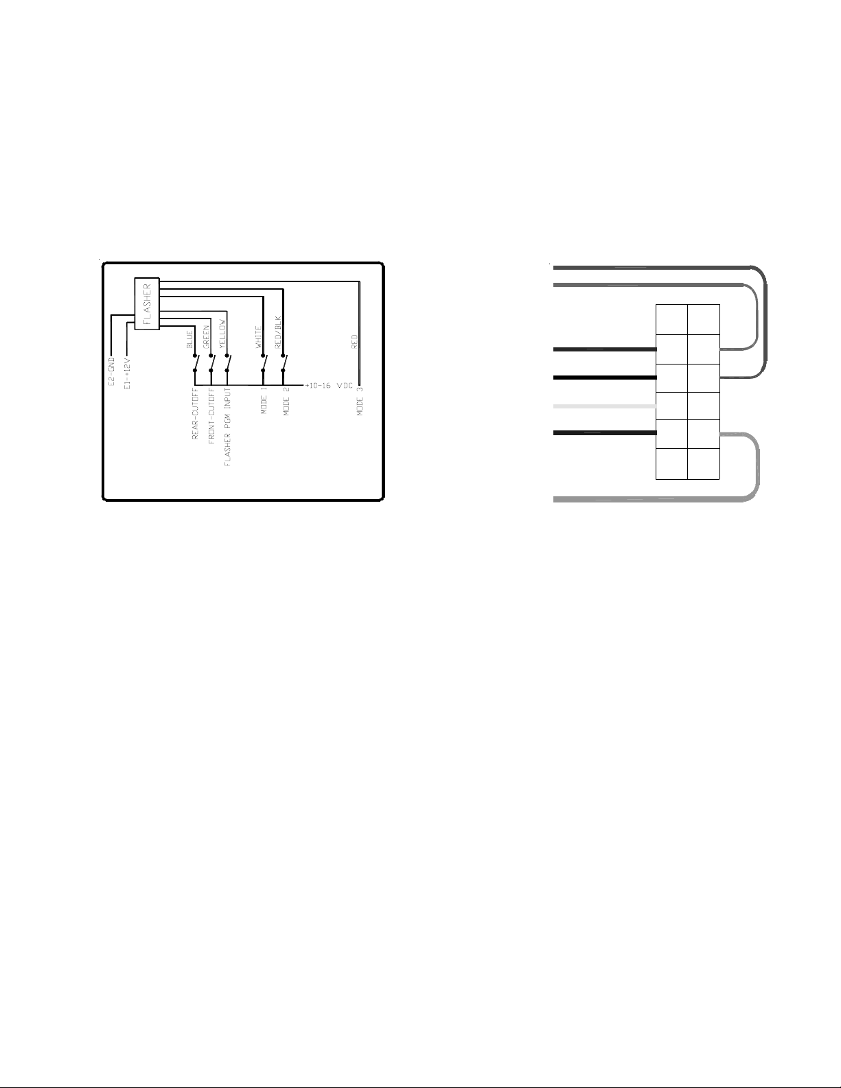
CONTROL HARNESS WIRE DESIGNATION:
2. Blue: 10-16V Rear Cutoff
3. Yellow: 10-16V Flash Pattern PGM
4. White: 10-16V Mode1
5. Brown: Not Used
8. Green: 10-16V Front Cutoff
10.Red/Blk: 10-16V Mode2
11.Red: 10-16V Mode3
12.Black: Not Used
18 AWG RED/BLACK
18 AWG RED
18 AWG BROWN
18 AWG WHITE
18 AWG YELLOW
6
12
5
11
4
10
3
9
18 AWG BLUE
2
8
7
1
Lightbar Version Wiring Diagram
18 AWG GREEN
Figure3
Figure4
2. Remote LED Flasher version p/n T08097:
This version has the same connector interface as the Low Profile version, except that this version utilizes
direct circuit board headers rather than wire harnesses. This Flasher can be used as a remote LED flasher to
drive Code 3 LED-EX and LED Perimeter lights. It can also be used as a motorcycle LED flasher.
INSTALLATION & WIRING
1. First, install the Flasher in a protected location using the flasher itself as a template. Make sure all connectors
are easily accessible. (Refer to Figure 5 and 6 for the following steps).
2. Plug in the Control Harness provided with the Flasher p/n T08115.
3. Connect the +12V and ground wires to quickslide terminals E1 & E2 respctively. Ensure that the +12V power
wire is fused with a 15 Amp Auto style fuse. Note: Use 14 Ga. wire for the main +12V and ground
connections.
4. Optional: Connect the yellow wire (flash pattern) program wire to +12V through a momentary switch. This
switch can be used to program a different flash pattern for regular and Interclear® operation. This wire can also
be taped away or permanently grounded after the flasher has been programmed with the desired patterns.
5. Optional: Connect the white (Interclear® Enable) wire to the active high interclear output on the siren if
applicable.
6. Connect the green (Group B & C Enable) wire and the blue (Group A Enable) wire to +12V through two use
supplied SPST switches. These switches could be used to activate groups A, B and C respectively.
7. Connect the brown (Photocell Input) and the black (Photocell Ground) wires to the red and black wires of the
photocell cable p/n T08086 if photocell activated Group C output dropout operation is desired. Otherwise, tie
these two wires together to disable this option.
3
Page 4

WIRE DESIGNATION:
2. Blue: 10-16V Group A Enable
3. Yellow: 10-16V Flash Pattern PGM (Momentary)
4. White: 10-16V Interclear® Enable
5. Brown: Photocell Input
7. Black: Photocell Ground
8. Green: 10-16V Group B & C Enable
10.Red/Blk: Not Used
11.Red: Not Used
18 AWG RED/BLACK
18 AWG RED
6
12
5
18 AWG BROWN
18 AWG WHITE
18 AWG YELLOW
11
4
10
9
3
18 AWG BLUE
18 AWG BLACK
18 AWG GREEN
Figure5
2
8
7
1
Remote Version Wiring Diagram
Figure6
Flash - Pattern Programming
A. Lightbar Version:
The desired flash pattern for any of the progressive operation modes 1, 2, & 3 can be programmed as follows:
1. Power one Mode-control wire at a time. Example: If the Mode1 flash pattern is to be programmed,
connect +12V to only the Mode1 control wire.
2. Connect the yellow (PGM) wire momentarily to +12V and release it to select the next available
pattern. Repeat until the desired pattern is selected. (refer to page 1 for available flash patterns)
3. Repeat steps 1 & 2 above for all three Mode-control wires one at a time. Note: Mode 3 overrides
Mode 2 and Mode 2 overrides Mode 1.
B. Remote Version:
1. Enable the blue and/or green wires first to select regular operation pattern.
2. Apply 10-16 VDC momentarily to the yellow wire, repeat until desired pattern is selected.
3. Repeat steps 1 & 2 enabling the white wire in addition to the blue and/or the green wire to select
the desired Interclear® mode flash pattern.
4. Tape or ground the yellow wire when programming is complete. Note: Interclear® Mode
overrides regular operation mode.
4
Page 5

CODE 3 LED-EX Lighthead Termination Instructions:
a) Strip coating back from wire 1/8".
b) Crimp wire into terminal at position 'A' and
crimp wire coating at position 'B' of AMP
WARNING!
socket P/N 61117-4.
c) Pull on wire to ensure a quality crimp
(soldering is recommended to ensure good
connection).
d) Insert pins into AMP connector # 1-480303-0
as shown in figure 8.
A
B
EXTENSION CABLE WIRING
MALE AMP CONNECTOR
(to terminate the LED-EX
Lighthead harness)
Insert wires with male pins into
the proper locations in the male
AMP connector:
POWER WIRE - HOLE #1
GROUND WIRE - HOLE#2
CONTROL WIRE - NOT USED
(if applicable)
Extension
Cable
IMPORTANT
For continued reliability, RTV or waterproofing grease
must be used on all terminals to prevent corrosion and
premature failure of the connections.
Install the LED light heads in the preferred locations.
String the 3 conductor cable between each individual
light and the Flasher. Make sure the cable is secure
along the chosen routing inside the vehicle to prevent
it from damage by chafing or binding. Be sure to keep
the cable away from engine hot spots.
Insert the AMP Mate & Lock pin contacts P/N 61118-4
on each end of the extension cables into the AMP
connectors P/N 1-480305-0. Each end of these cables
has a factory crimped terminal on each of the three
wires, see Figure 7.
Note: It is important to follow the correct color code
when inserting the pins into the AMP
connectors.
AMP-p/n 1-480305-0
FEMALE AMP CONNECTOR
AMP-p/n 1-480303-0
from LED
Lighthead
AMP-p/n 61117-4
Insert wires with female pins into
the proper locations in the female
AMP connector:
POWER WIRE - HOLE #1
GROUND WIRE - HOLE#2
CONTROL WIRE - HOLE #3(not connected)
Remote LED Lightheads (2 wire installation)
AMP-p/n 61118-4
Extension
Cable
Figure7
Code 3
LED-EX
Lighthead
1. Plug the extension cables to the LED light
heads.
2. Plug the other end of the cable into the light
head output socket on the flasher, see Figure 1.
RED
POWER WIRE - POSITION 1
BLACK
Self Contained LED-EX Lighthead in Steady-Burn Mode
GROUND WIRE - POSITION 2
Figure8
5
Page 6

NOTES:
6
Page 7

NOTES:
7
Page 8

WARRANTY
This product was tested and found to be operational at the time of manufacture. Provided this
product is installed and operated in accordance with the manufacturer's recommendations, Code 3,
Inc. guarantees all parts and components except the LED lamps for a period of 3 years from the
date of purchase or delivery, whichever is later. Units demonstrated to be defective within the
warranty period will be repaired or replaced at the factory service center at no cost.
Use of a load of a wattage higher than installed or recommended by the factory, or use of
inappropriate or inadequate wiring or circuit protection causes this warranty to become void. Failure
or destruction of the product resulting from abuse or unusual use and/or accidents is not covered by
this warranty.
Code 3, Inc. shall in no way be liable for other damages including consequential, indirect or
special damages whether loss is due to negligence or breach of warranty.
CODE 3, INC. MAKES NO OTHER EXPRESS OR IMPLIED WARRANTY INCLUDING,
WITHOUT LIMITATION, WARRANTIES OF FITNESS OR MERCHANTABILITY, WITH RESPECT
TO THIS PRODUCT.
PRODUCT RETURNS
If a product must be returned for repair or replacement*, please contact our factory to obtain
a Return Goods Authorization Number (RGA number) before you ship the product to Code 3, Inc.
Write the RGA number clearly on the package near the mailing label. Be sure you use sufficient
packing materials to avoid damage to the product being returned while in transit.
*Code 3, Inc. reserves the right to repair or replace at its discretion. Code 3, Inc. assumes no responsibility or liability for expenses incurred for the
removal and /or reinstallation of products requiring service and/or repair.; nor for the packaging, handling, and shipping: nor for the handling of products return to
sender after the service has been rendered.
NEED HELP? Call our Technical Assistance Hotline - (314) 996-2800
Code 3 is a registered trademarks
of Public Safety Equipment, Inc.
Public Safety Equipment, Inc.
St. Louis, Missouri 63114-2029—USA
Ph. (314) 426-2700 Fax (314) 426-1337
Revision 1, 9/06 - Instruction Book Part No. T08112
8
©2004 Public Safety Equipment, Inc. Printed in USA
10986 N. Warson Road
www.code3pse.com
Code 3,®Inc., a subsidiary of
Public Safety Equipment, Inc.
 Loading...