

Page 1

INSTALLATION
& OPERATION
MANUAL
MODEL
OLRD
OLDM
Patent Pending
IMPORTANT:
OSCILASER
TM
REAR DECK/DASH MOUNT
Contents:
Introduction..................................................................... 2
Unpacking & Pre-Installation .......................................... 2
Installation & Mounting ................................................ 2-3
Maintenance ................................................................... 4
Cleaning ......................................................................... 4
Changing Lamps ............................................................ 4
Troubleshooing............................................................... 5
Parts List (Replacement Parts / Exploded View) ............ 5
Warranty ......................................................................... 6
Read all instructions and warnings before installing and using.
INSTALLER: This manual must be delivered to the end user of this equipment.
Page 2

Introduction
The OLRD is an oscillating warning light designed to be mounted with the "L" bracket included in the rear deck
or front bumper of a vehicle. The OLDM is the same oscillating light assembly with the addition of a cord and
cigarette lighter plug, as well as an adjustable mounting bracket for use in the front windshield area of a
vehicle. Both of these highly effective warning light systems feature the OsciLaserTM light assembly with its
constant 35 watt for 12V and 32 watt for 24V Halogen signal that covers all areas within its field of illumination
at least once per second.
The use of this or any warning device does not insure that all drivers can or will observe or
react to an emergency warning signal. Never take the right-of-way for granted. It is your
responsibility to be sure you can proceed safely before entering an intersection, driving
against traffic, responding at a high rate of speed, or walking on or around traffic lanes.
The effectiveness of this warning device is highly dependent upon correct mounting and
wiring. Read and follow the manufacturer’s instructions before installing or using this
device. The vehicle operator should insure daily that all features of the device operate
!
WARNING!
correctly. In use, the vehicle operator should insure the projection of the warning signal is
not blocked by vehicle components (i.e.: open trunks or compartment doors), people,
vehicles, or other obstructions.
This equipment is intended for use by authorized personnel only. It is the user’s responsibility to understand and obey all laws regarding emergency warning devices. The user
should check all applicable city, state and federal laws and regulations.
Public Safety Equipment, Inc., assumes no liability for any loss resulting from the use of this
warning device.
Proper installation is vital to the performance of this warning device and the safe operation
of the emergency vehicle. It is important to recognize that the operator of the emergency
vehicle is under psychological and physiological stress caused by the emergency situation.
The warning device should be installed in such a manner as to: A) Not reduce the output
performance of the system, B) Place the controls within convenient reach of the operator
so that one can operate the system without losing eye contact with the roadway.
Emergency warning devices often require high electrical voltages and/or currents. Properly
protect and use caution around live electrical connections. Grounding or shorting of
electrical connections can cause high current arcing, which can cause personal injury and/
or severe vehicle damage, including fire.
PROPER INSTALLATION COMBINED WITH OPERATOR TRAINING IN THE PROPER
USE OF EMERGENCY WARNING DEVICES IS ESSENTIAL TO INSURE THE SAFETY
OF EMERGENCY PERSONNEL AND THE PUBLIC.
Unpacking and Preinstallation
Carefully unpack the unit and check the contents against the parts list on page # 5 of this booklet. Be careful
to open the proper end of the OsciLaser light carton so the lens is not damaged or cut. Test the operation of
the OsciLaser light assembly before installation by connecting the red power wire to applicable +12 or 24 volt
D.C. lead and the black wire to ground (earth).
Installation and Mounting
Larger wires and tight connections will provide longer service life for components. For high
!
WARNING!
the current carrying capacity of wires, fuses, and circuit breakers. Use "SXL" type wire in
engine compartment. All wiring should conform to the minimum wire size and other
recommendations of the manufacturer and be protected from moving parts and hot
surfaces. Looms, grommets, cable ties, and similar installation hardware should be used to
current wires it is highly recommended that terminal blocks or soldered connections be used
with shrink tubing to protect the connections. Do not use insulation displacement
connectors (e.g. 3M® Scotchlock type connectors). Route wiring using grommets and
sealant when passing through compartment walls. Minimize the number of splices to
reduce voltage drop. High ambient temperatures (e.g. underhood) will significantly reduce
2
Page 3
anchor and protect all wiring. Fuses or circuit breakers should be located as close to the
power takeoff points as possible and properly sized to protect the wiring and devices.
Particular attention should be paid to the location and method of making electrical
!
WARNING!
NOTE : All of the information listed in this
booklet must be given to the end user by
the installer.
OLRD INSTALLATION:
connections and splices to protect these points from corrosion and loss of conductivity.
Ground terminations should only be made to substantial chassis components, preferably
directly to the vehicle battery. The user should install a fuse sized to approximately 125% of
the maximum Amp capacity in the supply line to protect against short circuits. For example, a
30 Amp fuse should carry a maximum of 24 Amps.
DO NOT USE 1/4" DIAMETER GLASS FUSES AS THEY ARE NOT SUITABLE FOR
CONTINUOUS DUTY IN SIZES ABOVE 15 AMPS.
Circuit breakers are very sensitive to high temperatures and will "false trip" when mounted in
hot environments or operated close to their capacity.
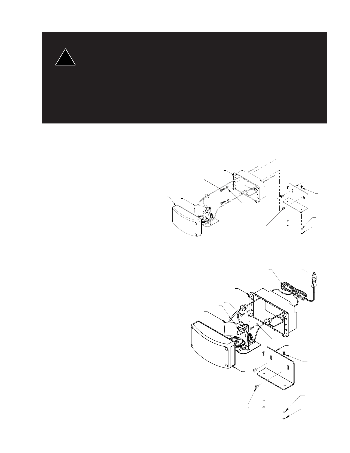
Mounting the L Bracket
1) Choose a suitable location for mounting
the Oscilaser , Using the square
mounting holes in the bottom of the
bracket as a template, mark the mounting hole positions. (NOTE: The bracket
bottom "L" can be turned either direction
based on mounting requirements.) Drill
one (5/16)" hole at each mark.
2) Using the supplied lockwashers, nuts,
and carriage bolts, mount the bracket to
the drilled holes. (See Figure 2.) Insure
that the fasteners are sufficiently tight.
Mounting the Oscilaser:
3) To install the Oscilaser to the "L"
Bracket, remove four lens screws and
pull lens from housing. Pull the Oscilaser
oscillating unit (Part #2) from housing.
4) Insert the supplied plastic inserts (Part
#7) into the back of the bracket. (Note:
push the inserts in from the side that the
light will be mounted on.)
5) Using the supplied screws and washers
(Parts #5 and #6, see Figure 1), attach
the housing to the inserts in the bracket.
Insure that the fasteners are sufficiently
tight.
6) Reassemble the Oscilaser, making sure
not to pinch the wires when tightening
the lens screws.
OLDM INSTALLATION:
The OLDM can be mounted with the "L"
Bracket in the same fashion as described above or it can be mounted using
the adjustable bracket.
TM
3
5
1
2
6
5
7
7
OLRD
FIGURE 1
11
3
5
13
2
5
3
1
OLDM
6
4
8
9
10
4
8
1) Assemble the Dash Mount bracket
according to Figure 2 or 3 per applicable
mounting.
2) Find a suitable flat mounting position for
the unit.
FIGURE 2
7
9
10
3
Page 4
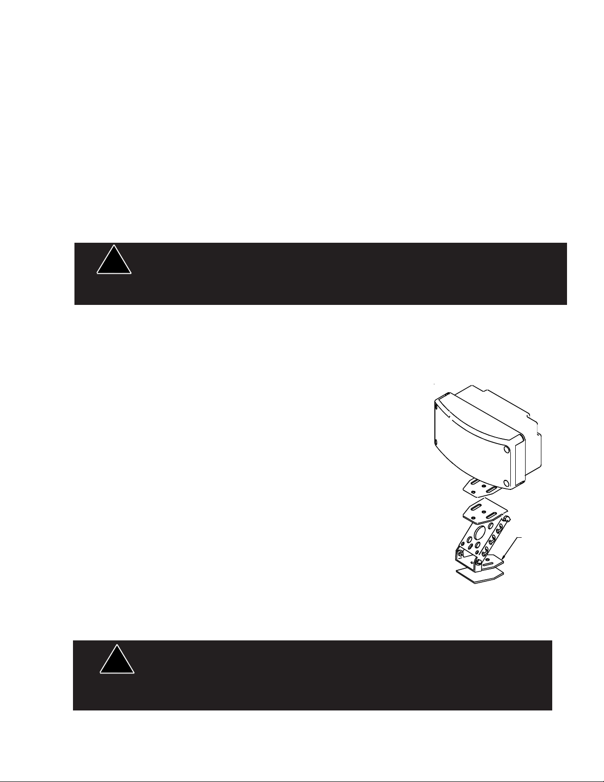
3) Peel the protective paper backing from one side of a piece of the double-sided tape and stick it to the top of
the bracket, (See Figure 3) for modes with adjustable mounting brackets.
4) Peel the remaining side of the paper and attach the bracket to the Oscilaser .
5) Peel the paper backing from one side of the other piece of double-sided tape and stick it to the bottom of
the bracket.
6) Remove the remaining side of paper and adhere it to the desired surface.
WIRING THE OSCILASER:
1) Using one of the supplied butt splices, connect the red power wire to the appropriate switched positive(+)
lead from the lighting control.
2) Using the remaining butt splice, connect the black ground (earth) wire to the vehicle chassis or a negative () wire lead.
(For fusing purposes, each Oscilaser draws approximately 4 amps.)
When mounting the OsciLaser
!
are securely fastened so that in the event of a collision they do not break free and injure the
vehicle occupants.
TM
units inside the vehicle on the rear deck, make sure they
WARNING!
Maintenance
If necessary, maintenance of your OsciLaser
involves the cleaning of the lens and the replace-ment of the lamp on the OsciLaser assembly.
Cleaning
Clean with soap and water to remove all salt, dirt or
mud. Do not use any abrasive cleaners or harsh
chemicals, because the polycarbonate lens will scratch
very easily. Polish the lens with PSE lens polish and a
soft paper cloth or towel.
Changing Lamps
To remove the lens, remove the 4 corner #8 x 5/8"
stainless steel screws. Using a glove or cloth for hand
protection, push in the defective lamp and turn counter
clockwise until the lamp can be removed. Install a new
Osram 64170 AX or equal bayonet-base lamp (non
ceramic base lamps are recommended) and replace
lens.
12
!
WARNING!
ADJUSTABLE MOUNTING BRACKET
FIGURE 3
Lamps are extremely hot! Allow to cool completely before attempting to remove. Gloves
and eye protection should be worn when handling halogen lamps as they are pressurized
and accidental breakage can result in flying glass.
4
Page 5

Troubleshooting guide
PROBLEM (OSCILASERTM LIGHT)
NO LIGHT AND NO OSCILLATION
PROBABLE CAUSE
1) OPEN CIRCUIT IN WIRING
2) LAMP AND MOTOR ARE
DEFECTIVE
3) SHORT CIRCUIT
REMEDY
1) CLOSE CIRCUIT BY CHECKING CONNECTIONS
2) RETURN OSCILASER
ASSEMBLY FOR REPAIR
3) CHECK FOR SHORTS IN LAMP
ASSEMBLY OR WIRING
OSCILLATES WITH NO LIGHT
LIGHT IS ON WITH NO OSCILLATION
LIGHT IS ON WITH SLOW OR
ERRATIC MOVEMENT OF OSCILASER
WATER IS COLLECTING IN HOUSING
UNIT BURNS FUSES/TRIPS CIRCUIT
BREAKERS
1) LAMP IS DEFECTIVE
2) WIRING TO LIGHT, IS LOOSE OR
DISCONNECTED.
1) MOTOR IS DEFECTIVE
2) WIRING TO MOTOR IS LOOSE
OR DISCONNECTED
1) OSCILASER ASSEMBLY IS
DEFECTIVE
2) LOW VEHICLE VOLTAGE
1) WIRING HOLES ARE NOT
SEALED PROPERLY
2) HOUSING GASKET IS DEFECTIVE
1) SHORT CIRCUIT
1) REPLACE LAMP
2) RECONNECT WIRE TO
OSCILASER LIGHT
1) RETURN ASSEMBLY FOR
REPAIR
2) RESOLDER WIRE TO MOTOR
1) RETURN ASSEMBLY FOR
REPAIR OR REPLACEMENT
2) CHECK VEHICLE VOLTAGE
1) RESEAL HOLES WITH CAULK
2) REPLACE HOUSING GASKET
ASSEMBLY
1) CHECK ASSEMBLY AND
WIRING FOR SHORT CIRCUIT
Parts & Exploded Views
Ref. Description Part No.
1 Green Lens T05530
2 OsciLaser Assembly S50031
3 Housing T03759
4 "L" Bracket S85897
5 Sheet Metal Screw (6 x 1/2,"B" pt) T06213
6 #6 Flat washer T10155
7 Plasti - Grommet T06521
8 C-Bolt, 5/16 - 18 x 3 1/2" T06716
9 5/16" Split Lockwashers T00245
10 Nut, Hex Head, 5/16" T00244
11 Cordset T01590
12 Adjustable Mounting Bracket S18314
13 Lamp 35 watt Halogen for 12V T01542
Clear Lens T05531
Red Lens T05532
Blue Lens T05533
Amber Lens T05534
Gasket T06512
Lamp 32 watt Halogen for 24V T05160
Parts Not Shown
Mounting Kit - Rear Deck and Dash mount T09004
HEYCO Snub bushings T06523
(2) for OLDM model only
5
Page 6

6
Page 7

7
Page 8

WARRANTY
This product was tested and found to be operational at the time of manufacture. Provided this product is installed and operated in accordance with the manufacturer's recommendations, Code 3, Inc. guarantees all parts and components except the lamps for a period
of 1 years from the date of purchase or delivery, whichever is later. Units demonstrated to be
defective within the warranty period will be repaired or replaced at the factory service center
at no cost.
Use of a lamp or other electrical load of a wattage higher than installed or recommended by the factory, or use of inappropriate or inadequate wiring or circuit protection
causes this warranty to become void. Failure or destruction of the product resulting from
abuse or unusual use and/or accidents is not covered by this warranty.
Code 3, Inc. shall in no way be liable for other damages including consequential, indirect or special damages whether loss is due to negligence or breach of warranty.
CODE 3, INC. MAKES NO OTHER EXPRESS OR IMPLIED WARRANTY INCLUDING, WITHOUT LIMITATION, WARRANTIES OF FITNESS OR MERCHANTABILITY,
WITH RESPECT TO THIS PRODUCT.
PRODUCT RETURNS
In order to provide you with significantly faster service, if you are going to return a
product for repair or replacement*, please contact our factory to obtain a Return Goods
Authorization Number (RGA number) before you mail the product to PSE. Write the RGA
number clearly on the package near the mailing label. Be sure you use sufficient packing
materials to avoid damage to the product being returned while in transit. All plastic domes
and optical lenses are NOT returnable for credit or exchange.
*PSE reserves the right to repair or replace product at its discretion. PSE assumes no responsibility or liability for
expenses incurred for the removal and/or reinstallation of products requiring service and/or repair.
NEED HELP? Call our Technical Assistance Hotline - (314) 996-2800
St. Louis, Missouri 63114-2029—USA
10986 N. Warson Road
Code 3, Inc.
www.code3pse.com
OsciLaser is a trademark and Code 3 is a registered trademark of Code 3, Inc. a subsidiary of Public Safety Equipment, Inc.
3M is a registered trademark of 3M Company
Revision 6, 02/2006 - Instruction Book Part No. T03405
©2002-6 Code 3, Inc. Printed in USA
 Loading...