

Page 1
INSTALLATION
& OPERATION
MANUAL
MODEL
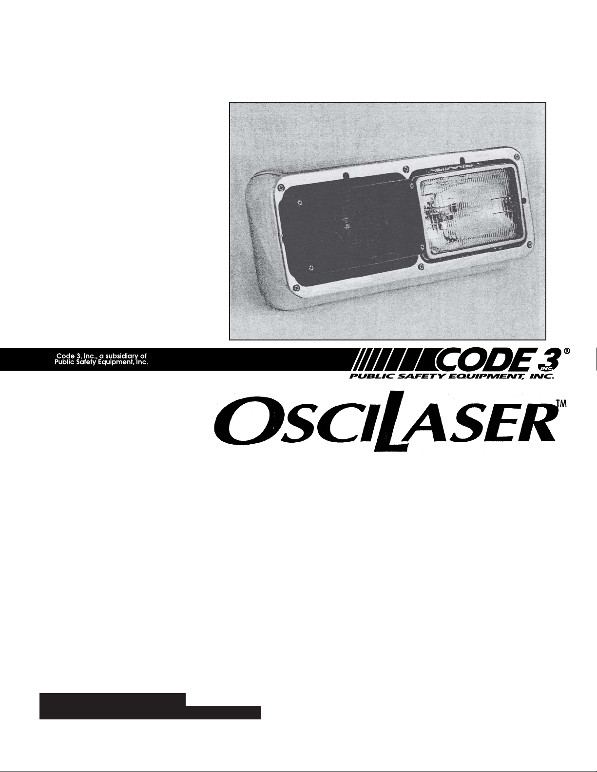
OL15F
Patent Pending
OSCILASER
IMPORTANT:
Read all instructions and warnings before installing and using.
INSTALLER:This manual must be delivered to the end user of this equipment.
TM
HEADLAMP MODULE
Contents:
Introduction.........................................................2
Unpacking & Pre-Installation .............................. 2
Installation & Mounting ....................................2-3
Maintenance.......................................................4
Cleaning ........................................................4
Changing Lamps ...........................................4
Troubleshooting............................................. 4
Parts List (Replacement Parts / Exploded View) 5
Warranty............................................................. 6
Page 2

Introduction
The OLF15 is an oscillating warning light for flush mounting into the headlamp housing of most firetrucks. This
highly effective warning light systems feature the OsciLaserTM light assembly with its constant 50 watt Halogen
signal that covers all areas within its field of illumination at least once per second.
The use of this or any warning device does not insure that all drivers can or will observe or
react to an emergency warning signal. Never take the right-of-way for granted. It is your
responsibility to be sure you can proceed safely before entering an intersection, driving
against traffic, responding at a high rate of speed, or walking on or around traffic lanes.
!
WARNING!
The effectiveness of this warning device is highly dependent upon correct mounting and
wiring. Read and follow the manufacturer’s instructions before installing or using this
device. The vehicle operator should insure daily that all features of the device operate
correctly. In use, the vehicle operator should insure the projection of the warning signal is
not blocked by vehicle components (i.e.: open trunks or compartment doors), people,
vehicles, or other obstructions.
This equipment is intended for use by authorized personnel only. It is the user’s responsibility to understand and obey all laws regarding emergency warning devices. The user
should check all applicable city, state and federal laws and regulations.
Public Safety Equipment, Inc., assumes no liability for any loss resulting from the use of this
warning device.
Proper installation is vital to the performance of this warning device and the safe operation
of the emergency vehicle. It is important to recognize that the operator of the emergency
vehicle is under psychological and physiological stress caused by the emergency situation.
The warning device should be installed in such a manner as to: A) Not reduce the output
performance of the system, B) Place the controls within convenient reach of the operator
so that one can operate the system without losing eye contact with the roadway.
Emergency warning devices often require high electrical voltages and/or currents. Properly
protect and use caution around live electrical connections. Grounding or shorting of
electrical connections can cause high current arcing, which can cause personal injury and/
or severe vehicle damage, including fire.
PROPER INSTALLATION COMBINED WITH OPERATOR TRAINING IN THE PROPER
USE OF EMERGENCY WARNING DEVICES IS ESSENTIAL TO INSURE THE SAFETY
OF EMERGENCY PERSONNEL AND THE PUBLIC.
Unpacking and Preinstallation
Carefully unpack the unit and check the contents against the parts list on page # 6 of this booklet. Be careful
to open the proper end of the OsciLaserTM light carton so the lens is not damaged or cut. Test the operation of
the OsciLaser light assembly before installation by connecting the red power wire to a +12 volt D.C. lead and
the black wire to ground (earth).
Installation and Mounting
Larger wires and tight connections will provide longer service life for components. For
high current wires it is highly recommended that terminal blocks or soldered connections be
!
WARNING!
used with shrink tubing to protect the connections. Do not use insulation displacement
connectors (e.g. 3M® Scotchlock type connectors). Route wiring using grommets and
sealant when passing through compartment walls. Minimize the number of splices to
reduce voltage drop. High ambient temperatures (e.g. underhood) will significantly reduce
the current carrying capacity of wires, fuses, and circuit breakers. Use "SXL" type wire in
engine compartment. All wiring should conform to the minimum wire size and other
recommendations of the manufacturer and be protected from moving parts and hot
surfaces. Looms, grommets, cable ties, and similar installation hardware should be used to
anchor and protect all wiring. Fuses or circuit breakers should be located as close to the
power takeoff points as possible and properly sized to protect the wiring and devices.
2
Page 3

Particular attention should be paid to the location and method of making electrical
connections and splices to protect these points from corrosion and loss of conductivity.
!
WARNING!
NOTE: All of the information listed in this booklet must be given to the end user by the installer.
The OL15F has a pair of hat shaped brackets mounted to the back of the unit. The upper bracket flanges
serve to close the gap above & below the Oscilaser when the headlamp bezel is installed. The lower
bracket is used to fasten the assembly to the headlamp housing itself.
The OL15F is intended to be mounted on the inner position of the headlamp housing.
These brackets are designed to adapt the Oscilaser to headlamp housings manufactured by either KD
LAMP or ADVANCED TECHNOLOGY. However, slightly different instructions apply depending on which
housing is used.
KD LAMP HOUSING:
This housing has an internal gusset at the end of the unit that interferes with the case of the Oscilaser as it is
lowered into the cavity. To eliminate this interference it is necessary to cut away a portion of this gusset. A
simple way to do this is to make a vertical cut, about 1/4" out from the wall of the housing. Sheet metal snips
may be used, cut down into the gusset about 3/4"-7/8". Then grasp the cut portion with a lineman’s pliers and
snap off. Remove and discard the cut away part of the gusset. Now the Oscilaser case and brackets may be
lowered into the cavity of the housing. Make the electrical wiring connection by inserting the male connector
into the female receptacle already in the wiring harness in the cavity of the housing. Next install the (2) no. 8
screws through the lower mounting bracket and through the hole in the flange of the housing. Add washers
and nuts but hand tighten only loosely. Then drop the bezel over the Oscilaser. The tight fit between the lens
on the Oscilaser and the opening in the bezel requires that the Oscilaser be positioned side to side exactly in
the center of the opening in the bezel. Move the Oscilaser by hand until the bezel can be pressed down over it
and seats against the housing bosses. Then carefully lift and remove the bezel so the Oscilaser lower
mounting bracket can be securely tightened down and fastened to the housing flange. Then the bezel can
be reinstalled and fastened down.
Ground terminations should only be made to substantial chassis components, preferably
directly to the vehicle battery. The user should install a fuse sized to approximately 125% of the
maximum Amp capacity in the supply line to protect against short circuits. For example, a 30
Amp fuse should carry a maximum of 24 Amps. DO NOT USE 1/4" DIAMETER GLASS
FUSES AS THEY ARE NOT SUITABLE FOR CONTINUOUS DUTY IN SIZES ABOVE 15
AMPS. Circuit breakers are very sensitive to high temperatures and will "false trip" when
mounted in hot environments or operated close to their capacity.
ADVANCED TECHNOLOGY HOUSING:
If this unit has been furnished with riveted in extension springs, to facilitate headlamp alignment, it will cause
an interference with the case of the Oscilaser. Only the upper portion of this spring will have to be cut off to
eliminate the interference with the Oscilaser. A heavy side cutter may be used to snip off the straight hook part
of the spring about 3/8" above the top coil. Now the Oscilaser case will fit into the cavity without interference.
First, the electrical wiring connections should be completed. The red power wire is to be connected to a
switched positive lead from a control switch. Attach the black ground (earth) wire to the vehicle chassis or an
available negative wire lead. For fusing purposes, each unit draws approximately 4 amps.
Now the Oscilaser case and brackets can be positioned in the housing cavity with holes in the lower bracket
aligned with the holes in the housing flanges. Install (2) no. 8 screws with flat & lock washers and nuts but
hand tighten only loosely. Then drop the bezel over the Oscilaser. The close fit between the Oscilaser lens
and the opening in the bezel requires that the Oscilaser be positioned side to side exactly in
3
Page 4

the center of the opening in the bezel. Move the Oscilaser by hand until the bezel can be slipped down
over it and seats against the housing bosses. Then carefully lift and remove the bezel so the Oscilaser
lower mounting bracket can be securely fastened down to the housing flanges. Then the bezel can be
reinstalled and fastened down.
Maintenance
If necessary, maintenance of your OsciLaser involves the cleaning of the lens and the replacement of the lamp on the OsciLaser assembly.
Cleaning
Clean with soap and water to remove all salt, dirt or mud. Do not use any abrasive cleaners or harsh
chemicals, because the polycarbonate lens will scratch very easily. Polish the lens with PSE lens polish and a
soft paper cloth or towel.
Changing Lamps
To remove the lens, remove the 4 corner #8 X 7/8" stainless steel screws. Using a glove or cloth for hand
protection, push in the defective lamp and turn counter clockwise until the lamp can be removed. Install a new
Osram 64170 AX or equal bayonet-base lamp (non ceramic base lamps are recommended) and replace
lens.
!
WARNING!
Lamps are extremely hot! Allow to cool completely before attempting to remove. Gloves
and eye protection should be worn when handling halogen lamps as they are pressurized
and accidental breakage can result in flying glass.
Trouble-shooting guide
PROBLEM (OSCILASER
LIGHT)
NO LIGHT AND NO OSCILLATION
OSCILLATES WITH NO LIGHT
LIGHT IS ON WITH NO OSCILLATION
LIGHT IS ON WITH SLOW OR
ERRATIC MOVEMENT OF OSCILASER
WATER IS COLLECTING IN HOUSING
TM
PROBABLE CAUSE
1) OPEN CIRCUIT IN WIRING
2) LAMP AND MOTOR ARE
3) SHORT CIRCUIT
1) LAMP IS DEFECTIVE
2) WIRING TO LIGHT, IS LOOSE OR
1) MOTOR IS DEFECTIVE
2) WIRING TO MOTOR IS LOOSE
1) OSCILASER ASSEMBLY IS
2) LOW VEHICLE VOLTAGE
1) WIRING HOLES ARE NOT
2) HOUSING GASKET IS DEFECTIVE
DEFECTIVE
DISCONNECTED.
OR DISCONNECTED
DEFECTIVE
SEALED PROPERLY
REMEDY
1) CLOSE CIRCUIT BY CHECKING CONNECTIONS
2) RETURN OSCILASER ASSEMBLY FOR
REPAIR
3) CHECK FOR SHORTS IN LAMP
ASSEMBLY OR WIRING
1) REPLACE LAMP
2) RECONNECT WIRE TO
OSCILASER LIGHT
1) RETURN ASSEMBLY FOR
REPAIR
2) RESOLDER WIRE TO MOTOR
1) RETURN ASSEMBLY FOR REPAIR
OR REPLACEMENT
2) CHECK VEHICLE VOLTAGE
2) REPLACE HOUSING GASKET
ASSEMBLY
1) RESEAL HOLES WITH CAULK
UNIT BURNS FUSES/TRIPS CIRCUIT
BREAKERS
1) SHORT CIRCUIT
1) CHECK ASSEMBLY AND WIRING
FOR SHORT CIRCUIT
4
Page 5

Lamps are extremely hot! Allow to cool completely before attempting to remove. Gloves
and eye protection should be worn when handling halogen lamps as they are pressurized
and accidental breakage can result in flying glass.
Parts & Exploded V iews
Ref Number Description Part No.
1 Lens T05530 (Green)
T05531 (Clear)
T05532 (Red)
T05533 (Blue)
T05534 (Amber)
2 OsciLaserTM Assembly S50031
3 Housing T03759
Gasket T06512
4 Lower Mounting Bracket T89856
5 Upper (Gap Closure) Bracket S89853
6 Lamp T01540 (50 watt halogenOsram 64170 AX)
7 #8-32 X 1/2" Machine Screw T02717
8 #10 Machine Screw Washer T00154
9 #8-32 Hex Head Nut T00391
5
Page 6

NOTES:
6
Page 7

NOTES:
7
Page 8

WARRANTY
This product was tested and found to be operational at the time of manufacture.
Provided this product is installed and operated in accordance with the manufacturer's
recommendations, Code 3, Inc. guarantees all parts and components except the lamps for a
period of 1 years from the date of purchase or delivery, whichever is later. Units demonstrated to be defective within the warranty period will be repaired or replaced at the factory
service center at no cost.
Use of a lamp or other electrical load of a wattage higher than installed or recommended by the factory, or use of inappropriate or inadequate wiring or circuit protection
causes this warranty to become void. Failure or destruction of the product resulting from
abuse or unusual use and/or accidents is not covered by this warranty.
Code 3, Inc. shall in no way be liable for other damages including consequential,
indirect or special damages whether loss is due to negligence or breach of warranty.
CODE 3, INC. MAKES NO OTHER EXPRESS OR IMPLIED WARRANTY INCLUDING, WITHOUT LIMITATION, WARRANTIES OF FITNESS OR MERCHANTABILITY,
WITH RESPECT TO THIS PRODUCT.
PRODUCT RETURNS
In order to provide you with faster service, if you are going to return a product for repair or replace-
ment*, please contact our factory to obtain a Return Goods Authorization Number (RGA number)
before you ship the product to Code 3. Write the RGA number clearly on the package near the mailing
label. Be sure you use sufficient packing materials to avoid damage to the product being returned while
in transit.
*Code 3, Inc. reserves the right to repair or replace product at its discretion and assumes no responsibility or liability for
expenses incurred for the removal and/or reinstallation of products requiring service and/or repair.
NEED HELP? Call our Technical Assistance Hotline - (314) 996-2800
St. Louis, Missouri 63114-2029—USA
10986 N. Warson Road
www.code3pse.com
Code 3, Inc.
OsciLaser is a trademark and Code 3 is a registered trademark of Code 3, Inc. a subsidiary of Public Safety Equipment, Inc.
3M is a registered trademark of 3M Company
Revision 1, 09/2006 - Instruction Book Part No. T09924
©1993 Public Safety Equipment, Inc. Printed in USA
 Loading...