

Page 1
INSTALLATION
&OPERATION
MANUAL
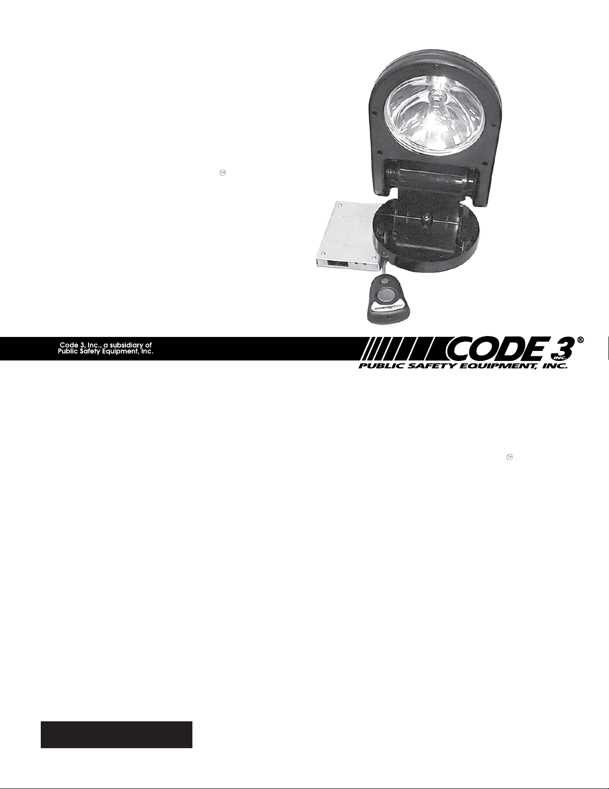
NIGHTPROBE
REMOTE CONTROLLED SPOTLIGHT
PATENT PENDING
NP 130
Contents:
NIGHTPROBE
REMOTE CONTROLLED SPOTLIGHT
Introduction (with warnings).......................................2
Unpacking & Pre-Installation.....................................2
Installation & Mounting................................................2
Controller Installation................................................3
Wiring Instructions ......................................................3
Maintenance ...................................................................4
Parts List (Replacement Parts/Exploded View) 5,6
Troubleshooting.........................................................7
Specifications .................................................................7
Warranty ........................................................................... 8
IMPORTANT:
TANT:
Read all instructions and warnings before installing and using.
INSTALLER: This manual must be delivered to the end user of this
equipment.
Page 2
The use of this or any warning device does not insure that all drivers can or will observe or
react to an emergency warning signal. Never take the right-of-way for granted. It is your
!
WARNING!
responsibility to be sure you can proceed safely before entering an intersection, driving
against traffic, responding at a high rate of speed, or walking on or around traffic lanes.
The effectiveness of this warning device is highly dependent upon correct mounting and
wiring. Read and follow the manufacturer’s instructions before installing or using this device.
The vehicle operator should insure daily that all features of the device operate correctly. In
use, the vehicle operator should insure the projection of the warning signal is not blocked by
vehicle components (i.e.: open trunks or compartment doors), people, vehicles, or other
obstructions.
This equipment is intended for use by authorized personnel only. It is the user’s responsibility to understand and obey all laws regarding emergency warning devices. The user should
check all applicable city, state and federal laws and regulations.
Code 3, assumes no liability for any loss resulting from the use of this warning device.
Note:
This device complies with Part 15 of the FCC Rules. Operation is subject to the following two
conditions: (1) This device may not cause harmful interference, and (2) this device must accept any
interference received, including interference that may cause undesired operation.
The user is cautioned that changes or modifications not expressly approved by CODE 3 for compliance
could void the user's authority to operate this equipment.
Introduction
The NightProbe , NP 130, product is a remote control spotlight that delivers more signal power and versatility
than any other spotlight product.
Its low profile aerodynamic lines reduce air drag, which results in fuel savings and stability at high speeds.
This product is made of shock-resistant high-temperature engineering thermoplastics and provides a warning
signal that exceeds SAE standards.
The NightProbe and its mounting system is designed to operate in many different locations including on the
driver side, passenger side or center of the automobile hood rear lip.
Unpacking & Pre-installation
Remove the spotlight from the box and examine the unit for transit damage. Refer to parts list to insure that all
parts are present for installation.
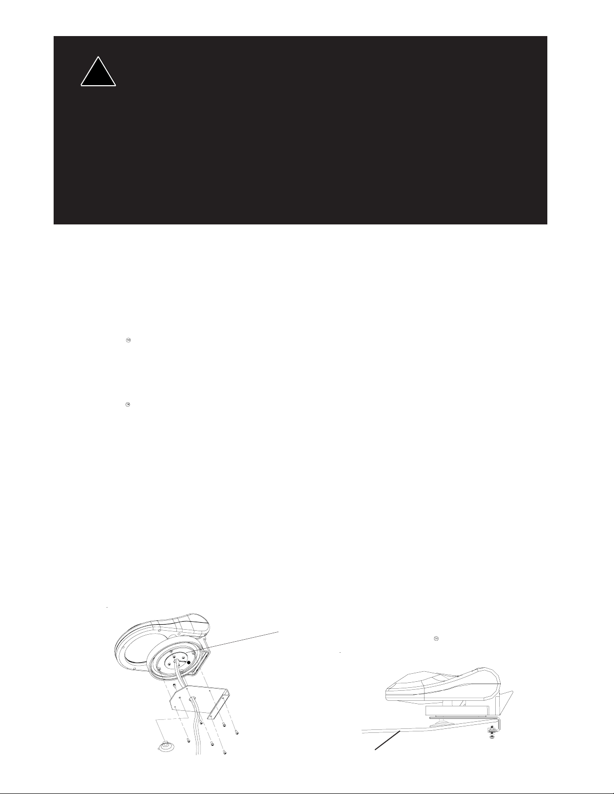
Installation & Mounting
1. Attach suction cup to bottom of mounting bracket with the #10 self tapping screw, do not over tighten.
2. Route the cables from the bottom of the spotlight through the mounting bracket as shown in Figure 1.
3. Attach bracket to spotlight with four round hd phillips 6-20 x 3/8" SS as shown in Figure 1.
4. Choose a location where the spotlight is to be mounted.
5. Lay out the cable to insure that there is an adequate amount to reach the area in which the controller is to
be mounted.
6. Fold wires into pocket of bracket in between the two mounting screws
7. Push bracket over lip of the hood and push down on suction cup
8. Tighten screws under hood until bracket is snug.
For proper bracket alignment make sure that
the mark is to rear of NightProbe as shown.
Figure 1
Vehicle
2
Page 3
Route wiring using grommets and sealant when passing through compartment walls. High
ambient temperatures (e.g. under-hood) will significantly reduce the current carrying capacity of
wires, fuses, and circuit breakers. Use "SXL" type wire in engine compartment. Minimize the
!
WARNING!
!
WARNING!
number of splices to reduce voltage drop. All wiring should conform to the minimum wire size
and other recommendations of the manufacturer and be protected from moving parts and hot
surfaces. Looms, grommets, cable ties, and similar installation hardware should be used to
anchor and protect all wiring. Particular attention should be paid to the location and method of
making electrical connections and splices to protect these points from corrosion and loss of
conductivity. Ground terminations should only be made to substantial chassis components,
preferably directly to the vehicle battery. The user should install a fuse sized to approximately
125% of the maximum amp capacity in the supply line and each switched circuit to protect
against short circuits.
Any electronic device may create or be affected by electromagnetic interference. After installation
of any electronic device, operate all equipment simultaneously to insure that operation is free of
interference.
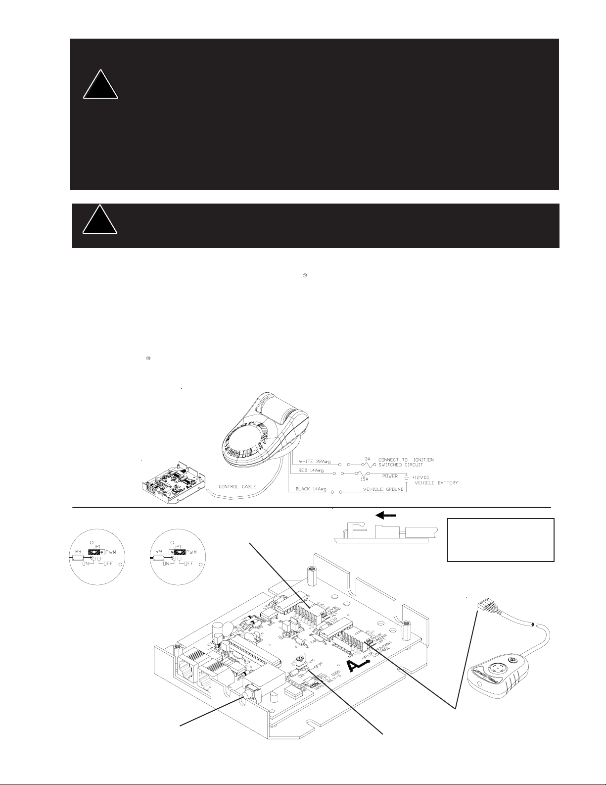
Wiring Instructions
Connect the red and black wires from the NightProbe spotlight as shown in Figure 2. Protect the circuit
with a 15 Amp fuse and use 14 awg (minimum) wire.
Connect the white wire from the unit to an ignition switched circuit protected by a fuse (3 Amp Max.). Use
a 22 awg. (minimum) wire.
IMPORTANT:
Failure to connect the wiring as stated above could cause damage to the unit.
The NightProbe spotlight must never have its lamp on when its head is in the closed position (as
shown in Figure 2). The extreme heat of the 100W lamp will damage the unit base.
Figure 2
PWM ON
NP130
Control Cable
Connector
Orientation
PWM OFF
IMPORTANT:
Make sure connector is
in the correct orientation
Figure 3
RF Remote
Training Switch
Pendant Cable
(Wired version only)
PWM Jumper
3
Page 4

Operation
The NightProbe is designed for Electro-mechanical use.
The Night Probe controller provides a four-position switch for lighthead movement and a push-on/push-off
switch for lamp control. The four-position switch provides either single-speed movement or Pulse Width
Modulated (PWM) acceleration from slowest to fastest speed. This feature is controlled by the position of
the PWM configuration jumper (JP1) which is located inside the Interface Module (see Figure 3). When
the PWM configuration jumper is set to the OFF position depressing and holding the four-position switch in
the LEFT, RIGHT, UP or DOWN direction will cause the Night Probe lighthead to rotate in the appropriate
direction in single speed mode. When the jumper is set to the ON position the Night Probe lighthead will
accelerate from it's slowest speed to full speed over a two second period and stop instantly when the
switch is released. This mode allows for very precise positioning of the light.
The NightProbe 130 RF is designed for use with an optional RF Remote Control.
The NP 130 RF Remote Control comes complete with battery installed. The NP 130 control must be
trained to recognize your remote unit. After installation, apply power to your NP130 system.
Depress and hold the training switch on the receiver located through a hole in the case near
the antenna (see Fig 3). While holding the training switch, depress and release the small
switch (Lamp ON/OFF) on the remote unit. Release the training switch and test the unit.
The RF Remote Control operation is the same as that described for the wired control.
Please note that radio transmitters and other electronic equipment can emit signals
which may interfere with the operation of the RF Remote Control and cause
temporary intermittent operation of the spotlight. This is considered normal. Warning!
CONTROLLER pendant and control module are NOT WATERPROOF
Figure 4
Maintenance
LAMPS ARE EXTREMELY HOT! ALLOW TO COOL COMPLETELY BEFORE ATTEMPT-
!
ING TO REMOVE. GLOVES AND EYE PROTECTION SHOULD BE WORN WHEN HANDLING HALOGEN LAMPS AS THEY ARE PRESSURIZED AND ACCIDENTAL BREAKAGE CAN RESULT IN FLYING GLASS.
WARNING!
Lamp Replacement
1. Insure that ignition is in off position.
2. Lift spotlight head so that it is facing up as in Figure 5.
3. Remove 7 screws in lower bulb shell and lift it off upper bulb shell.
4. Disconnect power and ground wire from lamp.
5. Replace lamp (H-3 100W) as shown in Figure 6.
6. Connect power and ground to lamp.
(IMPORTANT: FEED POWER AND GROUND WIRE BACK THROUGH
HEAT SHIELD WITH FABRIC SIDE FACING BULB AS SHOWN). Both wires must be positioned
behind the protective heatshield.
7. Be sure to align the upper and lower shells with the proper key on the vertical gear (see Figure 7)
Reattach the 7 screws. Do not overtighten.
H-3 100 watt lamp
lower shell key
Fabric side
Figure 5
Figure 6
upper shell key
Figure 7
4
Page 5

Parts & Exploded Views
10
Control Module
To Control Module
CR2032 Type Battery
11
To Control Module
5
Page 6

Parts List
Ref No. Description Part No. Qty.
1 SMS,Pan Hd Phil. #8 x 1/2"lg 'PT' screw T06828 0 7
2 Lower Bulb Shell T06878 0 1
3 H-3 100W Lamp T05379 0 1
4 Heat Shield T06881 0 1
5 Upper Bulb Shell T06877 0 1
6 Motor Housing S81832 01
7 Mounting Bracket S81835 01
8 SMS,Round Hd phil, 6-20 x 3/8", ss T01591 0 4
9 Ms, slot, Hx, Hd ,10-24 x 3/4"lg T06897 0 2
10 NP 130 Wired Control Module S71607 01
Wireless Control Module for S71607 S71613 01
11 NP 130 Wired Control Pendant S71615 01
NP 130 Wireless Control Pendent S71612 01
NOT SHOWN
Belt Clip T10974 01
Boot, vinyl-yellow T10975 01
Battery, CR2032 T10988 01
6
Page 7

Troubleshooting
PROBLEM
Product does not activate a. No power to unit a. Check wiring
Unit operates but no light a. Lamp burned out a. Replace lamp
b. Switch on controller not engaged b. Push button on controller
Light operates but unit not moving
Specifications:
PROBABLE CAUSE
b. Fuse blown b. Replace fuse
c. Ignition not on c. Turn on ignition
d. Controller cable not connected d. Check cable connection
f. Damaged or shorted cabling f. Check cables for damage
a. Motor damage a. Return to Code 3 Inc.
b. Unit hitting obstacle b. Remove obstacle
REMEDY
Mechanical Dimensions: Width: 7.25"
Rotation: 360 degrees
Electrical:
Operating Voltage: 10 - 15 VDC
Current draw:
Lamp 'on' approx. 10A @ 12.8 VDC
Lamp 'off' approx. 35mA @ 12.8 VDC
Lamp Rating 100 Watts @ 12.8 VDC
Depth: 12"
Height:
lamp down 4"
lamp raised 12"
Finishing:
To prepare the surface of the Night Probe for finishing wipe it with alcohol
or clean ultrasonically.
Mask off all bearing surfaces before finishing.
Water base and solvent paints based on aliphatic hydrocarbons (mineral
spirits, heptane, hexane and alcohols) have good compatibility with the
Night Probe material.
Chlorinated and aromatic solvents, as well as ketones should generally be
avoided.
Curing:
Paints used on the Night Probe material can be cured using either air-dry
or bake techniques. Circulating warm air ovens are the best suited and
most economical method of drying.
Curing conditions will vary depending on the coating and part design. Bake
temperatures of 250 degrees F (121degrees C) are acceptable with Night
Probe material.
7
Page 8

WARRANTY
Code 3, Inc.'s emergency devices are tested and found to be operational at the time of
manufacture. Provided they are installed and operated in accordance with manufacturer's
recommendations, Code 3, Inc. guarantees all parts and components except the lamps to a period
of 1 year (unless otherwise expressed) from the date of purchase or delivery, whichever is later.
Units demonstrated to be defective within the warranty period will be repaired or replaced at the
factory service center at no cost.
Use of lamp or other electrical load of a wattage higher than installed or recommended by the
factory, or use of inappropriate or inadequate wiring or circuit protection causes this warranty to
become void. Failure or destruction of the product resulting from abuse or unusual use and/or
accidents is not covered by this warranty. Code 3, Inc. shall in no way be liable for other damages
including consequential, indirect or special damages whether loss is due to negligence or breach of
warranty.
CODE 3, INC. MAKES NO OTHER EXPRESS OR IMPLIED WARRANTY INCLUDING,
WITHOUT LIMITATION, WARRANTIES OF FITNESS OR MERCHANTABILITY, WITH RESPECT TO THIS PRODUCT.
PRODUCT RETURNS
If a product must be returned for repair or replacement*, please contact our factory to obtain
a Return Goods Authorization Number (RGA number) before you ship the product to Code 3, Inc.
Write the RGA number clearly on the package near the mailing label. Be sure you use sufficient
packing materials to avoid damage to the product being returned while in transit.
*Code 3, Inc. reserves the right to repair or replace at its discretion. Code 3, Inc. assumes no responsibility or liability for expenses incurred for the
removal and /or reinstallation of products requiring service and/or repair; nor for the packaging, handling, and shipping; nor for the handling of products return to
sender after the service has been rendered.
PROBLEMS OR QUESTIONS? CALL OUR TECHNICAL ASSISTANCE HOTLINE (314) 996-2800
WWW.CODE3PSE.COM
St. Louis, Missouri 63114-2029—USA
Ph. (314) 426-2700 Fax (314) 426-1337
Code 3® is a registered trademark of Code 3, Inc., a subsidiary of Public Safety Equipment, Inc.
Part No. T06888 Rev. 7 5/2006
10986 N. Warson Road
Code 3®, Inc.
©2005 Code 3, Inc
8
 Loading...