

Page 1
1601 J. P. Hennessy Drive, LaVergne, TN USA 37086-3565 615/641-7533 800/688-6359 Manual Part No.: 8112596 01
HENNESSY INDUSTRIES INC. Manufacturer of AMMCO
®
, COATS®and BADA®Automotive Service Equipment and Tools. Revision: 08/99
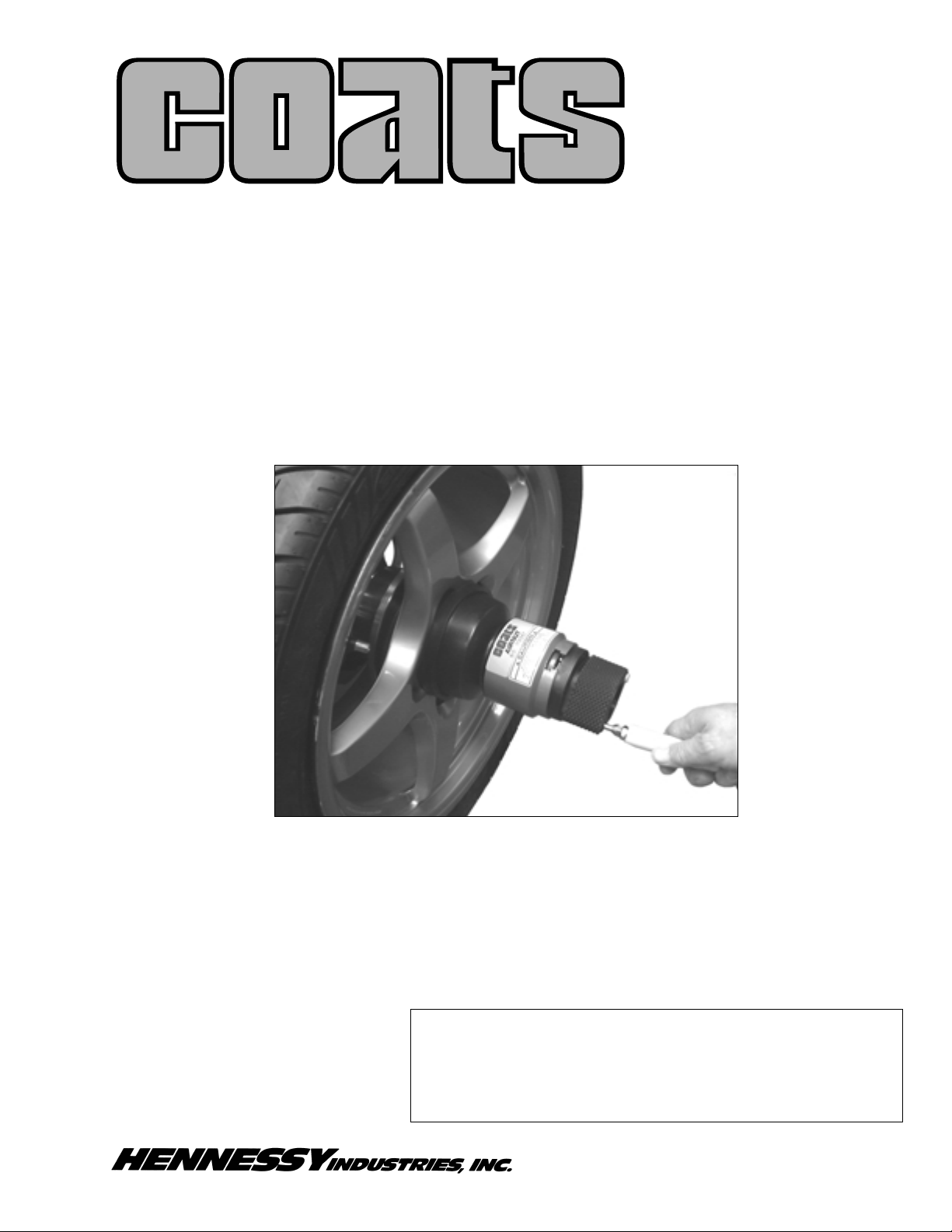
AirNut
No. 8112567 (1.1258”) ID
No. 8112568 (40mm) ID
For Use on COATS Wheel Balancers
®
Installation Instructions
Operating Instructions
Safety Instructions
Maintenance Instructions
READ these instructions before placing unit in
service KEEP these and other materials delivered
with the unit in a binder near the machine for
ease of reference by supervisors and operators.
Page 2

ii • COATS AirNut
Contents
Table of Contents
Owner’s Responsibilitiy . . . . . . . . . . . . . . .iii
Definitions of Hazard Levels . . . . . . . . . . . .iii
Important Safety Instructions . . . . . . . . . . .iv
Before You Begin
Receiving . . . . . . . . . . . . . . . . . . . . . . . . . . . . . .1
Specifications . . . . . . . . . . . . . . . . . . . . . . . . . . .1
Air Requirements . . . . . . . . . . . . . . . . . . . . . . . .1
Standard Accessories . . . . . . . . . . . . . . . . . . . . .1
Optional Accessories . . . . . . . . . . . . . . . . . . . . . .1
Assembly and Setup
Unpacking the Unit . . . . . . . . . . . . . . . . . . . . . . .2
Standard Parts List . . . . . . . . . . . . . . . . . . . . . . .2
Initial Testing of the AirNut . . . . . . . . . . . . . . . .2-3
Operating the AirNut
General Instructions . . . . . . . . . . . . . . . . . . . . . .3
AirNut Engagement . . . . . . . . . . . . . . . . . . . . . . .3
AirNut Release . . . . . . . . . . . . . . . . . . . . . . . . . .3
Maintenance and Service
Preventative Maintenance . . . . . . . . . . . . . . . . . .4
Service . . . . . . . . . . . . . . . . . . . . . . . . . . . . . . . .4
Troubleshooting . . . . . . . . . . . . . . . . . . . . . .4
Parts Identification . . . . . . . . . . . . . . . . . . . .5
Page 3
COATS AirNut • iii
Owner’s Responsibility
To maintain machine and user safety, the responsibility
of the owner is to read and follow these instructions:
• Follow all installation instructions and make sure
installation conforms to all applicable Local, State,
and Federal Codes, Rules, and Regulations; such as
State and Federal OSHA Regulations and Electrical
Codes.
• Carefully check the unit for correct initial function.
• Read and follow the safety instructions. Keep them
readily available for machine operators.
• Make certain all operators are properly trained,
know how to safely and correctly operate the unit,
and are properly supervised.
• Allow unit operation only with all parts in place and
operating safely.
• Carefully inspect the unit on a regular basis and perform all maintenance as required.
• Service and maintain the unit only with authorized
or approved replacement parts.
• Keep all instructions permanently with the unit and
all decals/labels/notices on the unit clean and visible.
Definitions of Hazard
Levels
Identify the hazard levels used in this manual with
the following definitions and signal words:
DANGER
Watch for this symbol:
It Means: Immediate hazards, which will result in
severe personal injury or death.
WARNING
Watch for this symbol:
It Means: Hazards or unsafe practices, which could
result in severe personal injury or death.
CAUTION
Watch for this symbol:
It Means: Hazards or unsafe practices, which may
result in minor personal injury or product or property
damage.
Watch for this symbol! It means BE ALERT! Your
safety, or the safety of others, is involved!
Safety
Failure to follow danger, warning, and caution
instructions may lead to serious personal
injury or death to operator or bystander or
damage to property. Do not operate this
machine until you read and understand all the
dangers, warnings and cautions in this manual. For additional copies of either, or further
information, contact:
Hennessy Industries, Inc.
1601 J.P. Hennessy Drive
LaVergne, TN 37086-3565
(615) 641-7533 or (800) 688-6359
www.ammcoats.com
DANGER
WARNING
CAUTION
WARNING
Page 4

iv • COATS AirNut
Safety
IMPORTANT SAFETY INSTRUCTIONS
SAVE THESE INSTRUCTIONS
READ ALL INSTRUCTIONS
1. Read all instructions
2. Never touch AirNut while the balancer arbor shaft
is in motion. Dismemberment and/or serious lacerations can occur.
3. Failure to push the AirNut on far enough for it to
tighten properly may result in the wheel dismounting, causing personal injury and property
damage.
4. When activating the AirNut, keep all body parts
from between the back side of the wheel’s center
and balancer face plate.
5. When activating the AirNut, keep all body parts
from between the front side of the wheel’s center
and the AirNut pressure cup/nylon spacer.
6. When de-activating the AirNut, keep all body parts
from between the back side of the pressure cup,
no mar ring and AirNut.
7. Adequate ventilation should be provided when
working on internal combustion engines.
8. Keep hair, loose clothing, fingers, and all body
parts away from moving parts.
Only use air gun for intended purpose. If air
is injected into the human body, lacerations, serious injuries, or death can occur.
9. Do not use the AirNut inflation device for any
other use than the inflation of the AirNut. Air
injected into the human body may lead to serious
injuries and often death.
10. Use only as described in this manual. Use only
manufacturer’s recommended attachments.
11. ALWAYS WEAR SAFETY GLASSES. Everyday
glasses only have impact resistant lenses, they
are NOT safety glasses.
12. Replace any damaged or missing safety decals.
They are available from COATS, (615) 641-7533.
13. Read and understand this manual before operating. Abuse and misuse will shorten functional life.
14. Keep guards and safety features in place and in
working order.
15. Wear proper clothing. Safety toe, non-slip
footwear and protective hair covering to contain
hair are recommended. Do not wear jewelry,
loose clothing, neckties, or gloves when operating
the balancer.
16. Keep work area clean and well lighted. Cluttered
and/or dark areas invite accidents.
17. Repair or replace any part that is damaged or worn
and that may cause unsafe balancer operation. Do
not operate damaged equipment until it has been
examined by a qualified service technician.
18. Do not allow untrained persons to operate
machinery.
19. Do not disable hood safety interlock system, or in
any way shortcut safety controls and operations.
WARNING
Page 5

COATS AirNut • 1
Before You Begin
Receiving
The shipment should be thoroughly inspected as
soon as it is received. The signed bill of lading is
acknowledgement by the carrier of receipt in good
condition of shipment covered by our invoice. If any of
the goods called for on this bill of lading are shorted or
damaged, do not accept them until the carrier makes
a notation on the freight bill of the shorted or damaged goods. Do this for your own protection.
NOTIFY THE CARRIER AT ONCE if any hidden loss or
damage is discovered after receipt and request the
carrier to make an inspection. If the carrier will not do
so, prepare a signed statement to the effect that you
have notified the carrier (on a specific date) and that
the carrier has failed to comply with your request.
IT IS DIFFICULT TO COLLECT FOR LOSS OR DAMAGE AFTER YOU HAVE GIVEN THE CARRIER A
CLEAR RECEIPT.
File your claim with the carrier promptly. Support
your claim with copies of the bill of lading, freight bill,
invoice, and photographs, if available. Although
COATS’ responsibility ceases upon delivery of the
shipment to the carrier, we will gladly assist in tracing
lost shipments. Our willingness to assist in every possible manner does not make COATS responsible for
collection of claims or replacement of lost or damaged
materials. Shipping damage claims will not be handled
under warranty.
Specifications
Minimum Air Pressure Required . . . . . . . .120 PSI
Maximum Air Pressure Required . . . . . . . .200 PSI
Clamping Force . . . . . . . . . . . . . . . .*Over 850 lbs.
Weight . . . . . . . . . . . . . . . . . . . . . . . . . . . .3.5 lbs.
Capacity . . . . . . . . . . . . . . . . . . . . .Extends 1.250"
*At Minimum Pressure
Air Requirements
Connect to an air supply that delivers between 120
PSI to 200 PSI.
For convenience to the user and longevity of the
AirNut…
• Run a separate air line to the balancer.
• Mount the regulator assembly and air gun to the
wheel balancer’s hood as outlined in the instructions on page 2.
• Add a water trap and oiler to the air line that will
feed the AirNut.
Standard Accessories
The following are standard accessories included with
the AirNut.
1. Pressure Cup (Part #112579)
2. Rubber Cushion (Part #112580)
3. No Mar Ring (Part #112581)
Figure 1 - Standard Accessories
Optional Accessories
There are two optional accessories available for the
AirNut.
1. Alu-Cup pressure cup (Part #112382) fits 40mm
shaft or (Part #111518) fits 1 1/8 shaft.
Figure 2 - Alu-Cup pressure cup
2. Inline water trap and oiler (Part #110495)
Figure 3 - Inline water trap and oiler
AirNut
#112581#112580#112579
Drain
Petcock
Air In
Oil Flow
Adjust
Oil Fill
Separator
Lubricator
Air Out
Page 6

2 • COATS AirNut
AirNut
Assembly and Setup
Unpacking the Unit
Remove all pieces from the container.
Lay them out and check contents against included
standard parts list on this page.
Standard Parts List
1. AirNut
2. Pressure Cup
3. Rubber Cushion
4. No Mar Ring
5. Regulator Assembly
6. Block Air Assembly with Gun Holder
7. Hose Assembly (Regulator to Block)
8. Hose Assembly (Block to Gun–Coiled Hose)
9. Air Gun
Figure 4 - AirNut standard parts
Initial Testing of the AirNut
1. Look through the center hole of the AirNut,
depress and release thumb lever; there should be
noticeable movement of the partial nut, the assembly
should work smoothly.
2. Depress the thumb lever and slide the AirNut
over the arbor shaft. Release thumb lever, pull outward to make sure it is held fast to the arbor shaft.
3. Depress the thumb lever and slide the AirNut off
the arbor shaft.
4. Temporally connect air to the Regulator/Inflator
assembly, and check to see that it will inflate the air
chamber of the AirNut. When fully inflated the piston
will have moved outward 1.250" (31.75mm).
5. Depress the yellow button to exhaust air from the
air chamber. The piston should retract.
6. The pressure cup and the No Mar Ring “snap”
into place on the front end of the AirNut.
Find the most convenient and handy spot on the
wheel balancer’s hood and mount the air gun and regulator assembly as shown in figure 5 below.
Figure 5 - Mounting on wheel balancer hood
7. Remove the rear self tapping screw and discard.
8. Drill a 1/4" hole through the hood and both sides
of the hood bar using the existing hole as a pilot.
9. Mount the block air assembly with gun holder
(item 6 in figure 4) as shown in figure 5.
10. Clean the plastic hood and apply the warning
decal as shown in figure 5.
Failure to secure the air hose as described
may result in severe personal injury if the
airline breaks.
5
6
7
8
9
1
2
3
4
WARNING
Page 7

COATS AirNut • 3
11. Route the airline from the block air assembly
around the inside of the hood and secure the air line
to the hood tube using the wire ties (supplied) as necessary.
12. Locate the regulator assembly on the rear of
the balancer and mark for the two pan head screws
(provided). Be careful to make sure the airline is positioned so that it does not interfere with hood movement as in figure 6.
13. Drill pilot holes and secure the regulator assembly.
14. Connect an airline to the regulator using a quick
coupler. Installation is now complete.
Do not apply more than 200 PSI to the regulator. If the available air supply exceeds
200 PSI, install an appropriate regulator to
reduce air pressure below 200 PSI.
Operating the AirNut
General Instructions
When the AirNut is activated it will extend 1.250"
(31.75mm)
The AirNut will slide freely over the threaded portion
of the arbor shaft when the thumb release is pressed
down. When the thumb release is released, the “partial nut” will engage the arbor shaft threads the AirNut
will be held in place.
The air chamber of the AirNut is activated by pushing
the air gun into the receiving port (opposite the yellow
button) found on the “hand end” of the AirNut. Air is
released through the inflator by pushing the air gun
towards and into the AirNut.
Air pressure is released from the AirNut by pressing
on the yellow button until all air is exhausted from the
air chamber.
AirNut Engagement
Once the cone and wheel are positioned on the balancer’s arbor shaft…
1. Depress the AirNut’s thumb nut release.
2. Slide the AirNut and pressure cup to the wheel
forcing the wheel against the balancer’s face plate.
Pinch Point
- When activating the AirNut
keep all parts of the body from between
wheel and faceplate and from between
AirNut and wheel.
3. Release the thumb nut while pushing inward
4. Remove the air gun from it’s holder.
5. Insert the air gun into the receiving end of the
AirNut to inflate.
Only use air gun for intended purpose. If air
is injected into the human body, lacerations, serious injuries, or death can occur.
Failure to properly tighten the AirNut may
result in the wheel dismounting, causing
personal injury and property damage.
AirNut Release
6. Depress the yellow button to release the air pres-
sure.
Never attempt to release a pressurized
AirNut using any method except by
depressing the yellow release button.
7. Press the thumb release to disconnect from the
arbor shaft.
8. Remove from arbor by pulling outward.
AirNut
WARNING
WARNING
WARNING
WARNING
WARNING
Page 8

4 • COATS AirNut
AirNut
Maintenance and
Service
Preventative Maintenance
For best results, an inline water trap and oiler should
be installed. To maintain it, follow the manufacturers
recommendations for servicing the water trap and
oiler.
1. Guard against rough handling of the AirNut.
2. Keep the partial nut, thumb lever assembly and
the balancer’s arbor shaft clean and free of any contaminant.
3. Avoid using strong solvents and chemicals for
cleaning. Compressed air and a light penetrating oil
such as WD 40 may be used to clean any part of the
AirNut.
4. There is a filter on the inlet to the air chamber
where the air gun is positioned for inflating. This filter
may be cleaned as described above.
Service
For any service you may require, call customer service (800) 688-6359 for an authorized service center
closest to you.
Troubleshooting
The AirNut has proved to be a very durable piece of
equipment. If maintained and handled properly, it
should give many years of good service.
Should any service be required review the following
section.
Look at the parts illustration on page 5.
1. There are four metric allen screws holding the
handle body to the main casting.
Once the four metric screws are removed and the
handle body is removed, the inlet and outlet valve
assemblies can be removed for cleaning, repair or
replacement. The correct placement of their air check
balls and springs is critical.
The partial nut, thumb release lever and spring may
be serviced when the handle body is separated from
the main casing.
If the AirNut won’t activate, check for air pressure
when the air gun is depressed.
2. Make sure there are no kinked air hoses.
3. Disconnect the air supply from the regulator and
make sure that supply of air is reaching the regulator.
4. If air pressure is present at the regulator, begin to
disconnect at each joint from the regulator and make
sure that supply of air is reaching the regulator.
5. If air pressure is present at the regulator, begin to
disconnect at each joint from the regulator to the gun
until the problem is located.
Wear safety glasses. There may be high air
pressure.
6. If air pressure is coming from the air gun but the
AirNut won’t activate, the filter is suspect. Clean with
WD 40 or equivalent.
If it still won’t inflate…
7. Inoperative inlet valve assembly.
8. If an air leak is noted in/on the AirNut, locate the
source and clean, repair or replace the component
part.
If the AirNut won’t engage with the arbor shaft
threads…
9. Arbor shaft threads are dirty and needs cleaning.
10. Partial nut is dirty and needs cleaning.
11. Partial nut thumb release is in need of disas-
sembly, cleaning or repair.
If the previous doesn’t fix the problem, call customer
service (800) 688-6359 for an authorized service center closest to you.
WARNING
Page 9

COATS AirNut • 5
Parts Identification
PART
ITEM NO. DESCRIPTION
1 8112666 Main Casing (1.125” model only)
8112667 Main Casing (40mm model only)
2 8112668 Air Release Assembly (valve body)
3 8112669 Air Supply Assembly (valve body)
4 8112579 Pressure Cup
5 8112580 Pressure Cup Cushion
6 8112581 No Mar Ring
7 8112671 Regulator Assembly
8 8112583 Air Hose Assembly (regulator to
block)
9 8112584 Air Gun
10 8112673 Air Hose Assembly (block to gun)
PART
ITEM NO. DESCRIPTION
11 8112672 Air Block Assembly
12 8112588 Holder (air gun) and Bolt Assembly
Not Shown
13 8112594 Decal (pinch point) Caution
14 8112595 Decal (air blast) Warning
15 8112590 Decal 1.125” Model
16 8112592 Decal 40mm Model
AirNut
1
2
3
5
6
7
8
9
10
11
12
4
Page 10

6 • COATS AirNut
AirNut
Notes
Page 11

COATS AirNut • 7
Notes
AirNut
Page 12

8112596 01 08/99 © Copyright 1999 Hennessy Industries and COATS, Inc. All Rights Reserved Printed in USA
 Loading...