

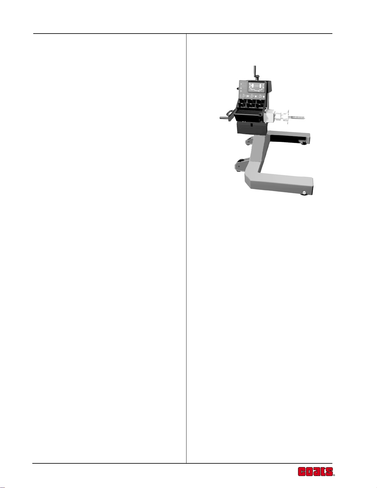
Page 1
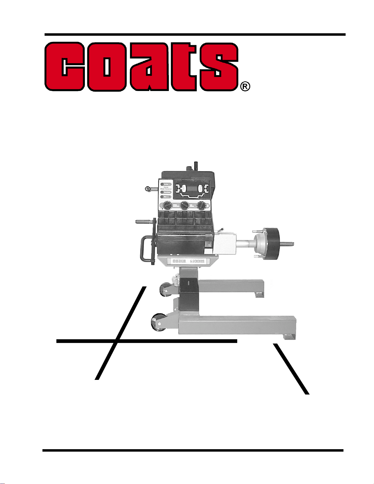
Truck Wheel Balancer
Model 6200HS
OPERA TION GUIDE
FORM 8184342
Page 2

Page 3

CONTENTS
Safety Cautions and Warnings ......................... ii
Installation ....................................................... iii
Unpacking ......................................................... iii
Assembly .......................................................... iii
Setup ................................................................ iv
Weight Increment Selection Mode ....................iv
12V Battery Operation ......................................iv
Introduction ...................................................... 1
Features .......................................................... 2
Accessories ..................................................... 3
Standard Adaptors ............................................ 3
Functional Description ..................................... 4
Balancer Display ............................................... 5
Input Panel ........................................................ 6
Offset Scale ...................................................... 7
Callipers ............................................................ 8
Accessory Storage ............................................ 8
Crank Handle .................................................... 8
Weight Storage ................................................. 8
Balancing Operation ........................................ 9
Operating Procedure ........................................ 9
Balancing Errors ............................................. 12
Weight Modes................................................ 13
Normal (clip-on) .............................................. 13
Alu/Mag ........................................................... 13
Static ............................................................... 14
Weight Location Dimensions .......................... 14
Special Applications ...................................... 15
Wheel Mounting Methods .............................. 17
Wheel Mounting Methods (Truck) .................. 17
Wheel Mounting Methods (Automobile) ......... 19
Power Sources .............................................. 23
Automatic Calibration..................................... 24
Calibration Procedure ..................................... 24
Calibration Errors ............................................ 25
Service and Maintenance .............................. 26
Operational Check .......................................... 26
Troubleshooting Guide .................................. 28
Technical Specifications ................................ 30
Operation Guide
i
Page 4

Coats Model 6200HS
SAFETY CAUTIONS AND WARNINGS
1. Read the Operators Manual before operating the
balancer for the first time. Follow all instructions
and warnings marked on the product.
2. The balancer operates from a) 110Vac, 60 Hz
wall outlet with the supplied 8.5Vac power
converter b) 12Vdc supply. Do not use any other
electrical sources. Use only an EARTHED
electrical power source. Use only a correctly rated
replacement fuse
3. Arrange the power cord so that it will not be tripped
over or pulled, and keep it clear of moving parts.
If an extension cord is used, ensure its current
rating equals that of the power cord supplied.
Immediately replace a damaged power cord.
4. Ensure the balancer rests on all three feet on a
clean, level floor with no debris under the base.
5. Do not operate the balancer: a) near fumes or
exposed flammable liquids; b) on wet surfaces.
Do not expose the balancer to rain.
.
6. Adopt the correct lifting procedures when lifting
any object. Weights in excess of 100lb (45kg)
should not be lifted unaided.
7. NEVER remove a cover or access panel on the
balancer without first disconnecting the balancer
from the electrical power source.
8. Only authorized and trained operators should use
the machine.
9. Wear approved eye protection when removing or
attaching weights. Keep hair, clothing and all parts
of the body clear of balancer moving parts.
10. Remove all stones, old weights, and other debris
from the wheel before balancing.
11. Centre and tighten the wheel on the shaft before
spinning the wheel.
12. Check that all wheel weights are properly applied
and secured.
13. The balancer will return to the normal power-up
state if the power is interrupted.
14. When the balancer is not in use, disconnect the
power cord and use the available pegs and trays
for storage of accessories.
ii
Page 5
INST ALLA TION
Your Model 6200HS Truck Balancer and accessories
will be delivered in a single carton mounted on a pallet.
Unpacking
A. Unpack the balancer and all accessories.
B. Check the contents list below and confirm that
all parts are present. Check also for the
standard wheel mounting accessories and any
optional accessories you may have ordered.
Qty Item
1 Balancer assembly.
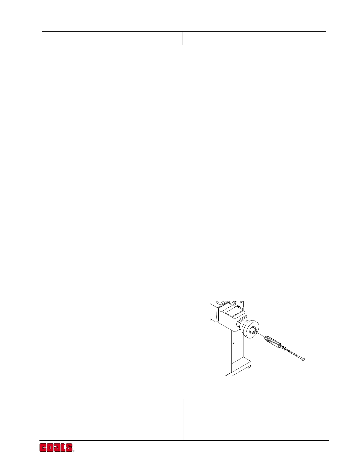
1 Stub shaft and bolt.
1 Plug-in power converter.
1 Light truck cone.
1 Medium truck cone.
1 Large truck cone.
1 Rim width Callipers.
1 Spacer Ring.
1 Hub nut assembly.
1 Operators manual.
Operation Guide
Assembly
Tools required : 10mm and ½” spanner
Philips screwdriver
9/16 thin wall socket
1. Place the balancer on a firm solid floor.
2. Fix the stub shaft to the spindle, by inserting the
bolt and 2 washers then tightening to a torque of
30Nm (110Ibsin -130Ibsin) using a 9/16 thin wall
socket.
3. Verify the correct voltage is shown on the product
serial label and the power converter supplied. Plug
the power converter into the mains outlet. Connect
the power converter cord to the input connector at
the rear of the balancer measuring head. The
balancer beeps and is switched on.
Your balancer is now ready for use!
iii
Page 6
Coats Model 6200HS
Setup
The balancer is programmed before leaving the factory
to display weight imbalance in grams. To change this
setting to ounce units, press oz/gram button, a decimal
point appears in the Display Window (0.00). Repeating
these steps will change the units back to grams (000).
Weight Increment Selection Mode
Machine is shipped in 25g (1oz) Increments to switch
to 50g (2oz) Increments, follow this procurdure.
1. With the machine powered off press and hold the
mode button.
2. Turn the power back on while still holding down
the mode button, wait about 7 seconds for the
machine to beep, machine is now in 50g (2oz)
increments.
Maintenance
1. Clean mounting accessories, mounting surface,
and spindle of balancer regularly. Grease and oil
accumulate dirt which can cause incorrect balance
results, and also act as a grinding compound
resulting in premature wear.
2. A light coating of grease should be maintained on
the sliding contact faces of the lifting section.
3. Remove wheel weights and rubbish from under
the balancer.
4. Do not lean any tyres, rims, tools or other parts
against the balancer.
5. Clean the Control Panel and Display Window with
window cleaner.
iv
Page 7
INTRODUCTION
The Coats Truck Balancer combines advanced, highperformance technology , robustness, reliability and
simplicity of operation.
The features of the Coats Truck Balancer cater for all
wheel service facilities. It is designed for use under a
wide range of conditions, and will maintain perfect
operation under the most demanding usage.
Low-speed rotation of the wheel by hand-spinning
ensures that the Coats Truck Balancer is one of the
safest machines available.
The Coats Truck Balancer offers complete portability
and features an easy-to-use Display and Input Panel,
ensuring quick and intuitive operation. Operator time
and effort are reduced to a minimum, while maintaining
wheel balancing accuracy and repeatability.
Operation Guide
Take a few minutes to study this manual and become
acquainted with the features and capabilities of your
new Coats Truck Balancer before operating the balancer
for the first time.
1
Page 8
Coats Model 6200HS
FEA TURES
The COATS computerized wheel balancer combines
state-of-the-art electronic accuracy with ease of use and
simplicity of design. Your COATS product will give you
years of reliable operation and wheel balancing profits.
The Balancer represent today ’s most advanced
concepts in wheel balancing with these high-precision
features:
Safe, accurate, low-speed operation
Balance Truck wheels to 5 gram accuracy
(Automobile wheels to 2 gram) at an operating
speed of only 70 rpm.
Fast and simple
-
With a single spin cycle of between 10 and 20
seconds (depending on wheel size) and a large
display that shows the exact weight requirement
and location, your balancer will promote
productivity and profits.
-
Electronic simplicity
-
All major components can be replaced in the
field, and the automatic self calibration program
allows the balancer to calibrate itself with little
or no downtime.
Six balancing modes-
Normal for standard clip-on weights on the
inner and outer rim flanges.
Static (single plane) for some specialty wheels.
Four Custom modes for combinations of clipon and stick-on weights, including hidden-weight
balancing.
Lightweight and Portable
-
The patented hand operated wheel lifting
mechanism (no pneumatics) and built in battery,
allow the balancer to be taken to the Truck. The
battery automatically recharges when the unit
is connected to the mains supply.
Economical
-
The balancer conserves energy by powering
down when not in use. Mounting a wheel
automatically powers up the unit again.
2
Page 9
ACCESSORIES
Standard Adaptors
Standard Wing Nut (P/N 8112103)
40 x 4 Shaft
Cone ( 3.25"-5.25") (P/N 8112101)
Operation Guide
Lt Truck Cone Kit (cone and backplate)
(P/N 8113277C)
Hub Centered Truck Cone Kit (cone and backplate)
(P/N 8111853C)
Not shown:
Rim Width Caliper (P/N 8309011)
Not shown:
AC Power Convertor 120V (P/N 6605-000101)
3
Page 10

Coats Model 6200HS
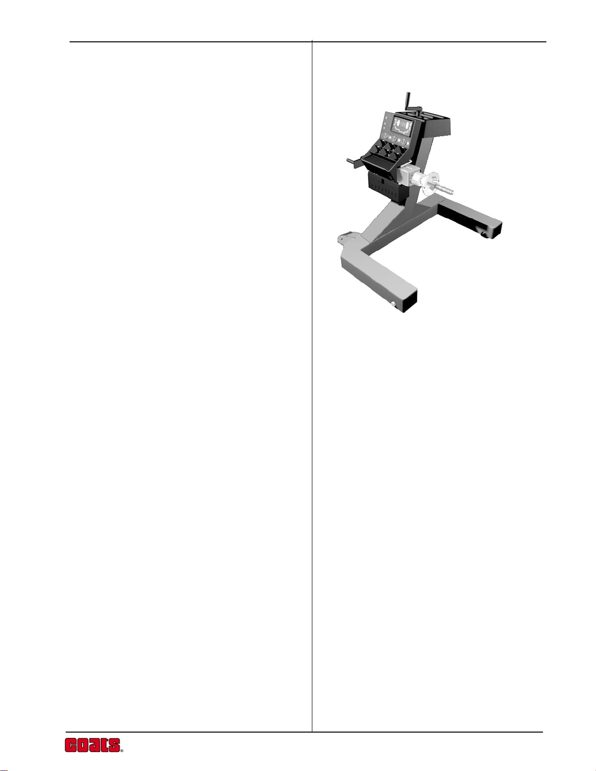
FUNCTIONAL DESCRIPTION
The following diagram shows a view from the front of the
complete assembled Truck Wheel Balancer.
1. Input Panel
2. Display Panel
3. Weights Storage
4. Offset Scale
2458
1
10
5. Stub Shaft
6. Flange
7. Hammer Holster
8. Accessory Storage
9. Crank Handle
10.Lift Handle
73 6
9
4
Page 11
Balancer Display
The display combines solid-state electronics and
graphical design to provide powerful visual presentation
and durability.
The display indicates the amount and position of
weights, wheel dimensions, operating modes and error
conditions.
1. Numeric Display
Operation Guide
Displays weights in grams or ounces after a spin cycle,
when the wheel is rotated to the inner or outer TopDead-Center position. Displays wheel dimensions
(diameter, width, offset) in inches or millimeters during
wheel data entry. Displays ‘EEE’ to report an error.
2. Decimal Point
Illuminated constantly when ounces are selected as
weight units.
3. Weight Position Indicators
Illuminated sequentially as the wheel is rotated and the
correct position for weight placement is approached.
This applies to both inner (3a) and outer (3b) weight
positions.
4. Top-Dead-Center Indicators
Illuminated when the correct position for attaching the
weight at Top-Dead-Center (TDC) is reached. There are
separate indicators for the inner (4a) and outer (4b) TDC
positions.
2
4a
3a 3b
6
7
1
5
4b
6
5. Rim Profile
Graphical rim profile to illustrate the Weight Mode in
operation.
6. Weight Mode Indicators
Illuminated Clip-On Weight (green, circular) and StickOn Weight (yellow, rectangular) indicators to
correspond to the Weight Mode selected.
7. Car Indicator
When the rim diameter is set at 17" or less the Car
Indicator will light. This allows wheels to be Fine
balanced to an accuracy of 2 grams (0.10 ounce). Refer
also to the
Calibration
Weight Location Modes
and
Automatic
sections of this manual for further details.
5
Page 12
Coats Model 6200HS
Input Panel
The input panel combines controls and indicators,
positioned for convenience, with graphical symbols
clearly defining each function.
The input panel is used to select and indicate specific
operating states and to enter data for the wheel to be
balanced and the weights to be used.
1. Ounce/Grams Button
This button is used to select Ounce/Grams and
Calibration. To change from ounces to grams or viseversa, hold the Ounce/Grams button while pressing the
"Fine" mode button.
2. Mode Select Button and Weight Location LED
Indicators.
The Mode Select Button works in conjunction with
the Weight Location LED Indicators on the Display, to
select the correct balance weight location. Weight
requirements are automatically recalculated when the
Mode is changed.
For easy and accurate custom mode operation, do the
balancing operation in the NORMAL (clip-on) Mode.
Then press the Mode Select Button for the desired
custom weight location. The balancer will automatically
recalculate the amount of weight required for the
selected weight location.
3. Fine Button.
Switches the balancer between Standard and Fine
resolution. The Fine LED Indicator lights when the
balancer is in Fine resolution.
4. Rim Diameter Knob.
1
2
3
Turn the Rim Diameter Knob to set rim diameter as
shown on the tire sidewall. Read the selection in the
Display Window.
5. MM Indicator.
Turning the Rim Diameter Knob fully counter clockwise
allows the rim diameter to be set in millimeters. When
the MM LED is lit the Display Window will show the
diameter in millimeters.
6
5
4
Page 13

6. Rim Width Knob.
Turn the Rim Width Knob to set rim width as measured
with the callipers. Read the selection in the Display
Window.
7. Offset Knob.
Turn the Offset Knob to set rim offset, or distance. Read
the selection in the Display Window.
Offset Scale
Offset, or rim distance, is a measurement of where the
wheel is mounted relative to the body of the balancer.
The offset scale measures this distance. The offset
scale is located at the top rear of the head. The offset
value is read at the point where the scale arm enters
into the housing. This value is input with the Rim Offset
dial on the input panel. The scale is spring-loaded and
will return to its resting position when released.
Operation Guide
6
7
Calipers
The calipers are used to measure the width of the rim
of the wheel being balanced. The width is then
programmed with the Rim Width dial on the input panel.
7
Page 14

Coats Model 6200HS
Accessory Storage (1)
The accessories can be stored on the protective shelving
at the back of the machine or on the moulded top tray.
Crank Handle (2)
The crank handle is fixed to the balancer and is used
to spin wheels mounted on the measuring head, in
cases where it is impossible to spin the wheel using
the standard hub nut (typically in the case of closedcenter wheels).
2
3
1
Weights Storage (3)
The moulded tray on the front and top of the balancer
contains compartments for weights and storage areas
for weight pliers and accessories.
8
Page 15

BALANCING OPERA TION
Operation of your Coats Truck Balancer is based on
LED indicators on the control panel, two soft-touch
buttons and three control knobs allow you to enter all
information needed for precision balancing. The display
indicates dimensions as they are entered.
Operating Procedure
The following Procedure covers the main steps for fast,
accurate wheel balancing with your Coats Truck
Balancer. Later sections of this manual contain detailed
information on weight location modes and wheel
mounting methods for your balancer.
1. Mount the wheel.
Operation Guide
Most original equipment and aftermarket wheels can
be mounted using some combination of the standard
mounting adapters. Refer to the
Methods
instructions.
2. Select the required Weight Locations.
Depress the Mode Select Button repeatedly until the
Weight Location Indicators display the chosen
locations.
3. Set the Rim Diameter Knob to the Diameter
section of this manual for more detailed
shown on the tire sidewall.
Wheel Mounting
Note: For tube type wheels with removable rim
flanges the diameter should be set to greater
than the nominal tire diameter. To display the
diameter in millimeters, turn the Diameter
Knob fully counter clockwise. The MM
Indicator will light and the diameter will be
shown in millimeters in the Display W indow.
When Diameter Knob is set at 17"(430mm) or
below the balancer automatically lights the Car
Indicator.
22.5
Rim
Diameter
9
Page 16

Coats Model 6200HS
4. Set the Rim Width Knob as measured with the
Calliper.
Note: If the tire is too wide to accept the callipers,
then measure over the thread width.
5. Set the Rim Offset Knob as follows.
a. Pull the rim offset scale arm out and position the
tip against the rim flange surface (regardless of
where the inner weight will be placed).
b. Read the rim distance value off the scale arm at
the point where it enters into the housing.
c. Set the Offset Knob to the rim distance value.
6. Spin the wheel.
7.00
6.50
a. Raise wheel using lift crank handle at top of
balancer. Wheel should clear the floor by
approximately 1/2"(13mm). Greater clearance is
unnecessary and would require additional cranking
to lower and stop the wheel.
b. Turn the spindle crank handle until a beep is heard.
Release handle immediately. Do not interfere with
the machine or wheel during the measuring cycle
or wrong readings can occur. Normal balance
speed is between 70 and 84 rpm. If spun too fast,
the buzzer will sound continuously until the wheel
slows to proper measurement speed. The balancer
will function normally even when a wheel is spun
too fast, however balancer cycle time will increase.
A second buzzing sound will indicate that the
measuring cycle is complete.
c. Stop the wheel by using the lift crank handle to
lower the wheel until it touches the ground. Car/
Light Truck Wheels can be stopped by using the
weight hammer against the tire side-wall.
10
Note: Do not use your hand to stop
the wheel.
Page 17

7. Attach the Weight.
a. Starting with either side of the wheel, rotate the
wheel in the direction of the lit arrow until all 6
Arrow Indicators and the Top Dead-Center Indicator
are lit. The correct balance weight will now be
displayed.
b. Securely apply the displayed weight at the top-
dead-center location on the indicated side of the
wheel.
c. Repeat steps 7a and 7b for the other side of the
wheel.
8. Do a Check Spin
Operation Guide
Repeat the spin cycle (step 6). Zero weight readings
should appear for both sides of the rim.
Optional:
If desired wheels may also be Fine Balanced
to 2 gram (Car/Light Truck) or 5 gram (Truck) accuracy.
Press the Fine Button on the left side of the Control
Panel. It is necessary to spin the wheel again when
the Car LED is lit, as the balancer calculates the fine
balancing requirements from the previous
measurements, and the Display will show the weight
requirements. When balancing Truck wheels, it is
necessary to re-spin the wheel after switching to Fine.
If a repeatable balance can not be achieved, there is a
possibility of foreign material moving around inside of
the tire causing a different imbalance every time. This
material must first be removed before the wheel can
be balanced.
11
Page 18

Coats Model 6200HS
Balancing Errors.
The crank handle has a one-way clutch for operator
safety, which also ensures that the wheel is spun in
the correct direction. It is however possible to spin the
wheel in the wrong direction (counter clockwise) when
using the Hub Nut. If this error occurs it will be identified
by an ‘EEE’ appearing in the Display Window.
If the wheel is intentionally (manually aborted) or
accidentally (wheel touches floor or operator) slowed
or stopped during the measuring cycle, ‘EEE’ will also
appear in the Display Window.
Spinning the wheel in the proper direction up to
balancing speed will remove this error and allow the
balancer to function normally.
In some cases when a very light wheel (i.e. a 13"
automobile wheel) is being balanced, ‘EEE’ may
appear. Re-spinning at a higher speed will prevent this
occurring and allow such wheels to be balanced.
12
Page 19

WEIGHT MODES
The COATS balancer features one Normal (clip-on) and
four Custom (Alu/Mag) Modes for combinations of clipon and stick-on weight s. A st atic balancing mode is
also included.
As the Mode Select Button on the control panel is
pressed, the Weight Location LED Indicators on the
Display Panel indicate the desired weight location.
When placing the weights for any of the Alu/Mag
modes, observe the location dimensions shown
opposite. Note also that these dimensions differ for Car/
Light Truck (diameter set below 17") and Truck wheels.
The balancer is programmed for these dimensions,
other placement locations will require different weights.
Normal: LED’s 1 and 5 light to indicate standard clip-
on weights on the inner and outer rim flanges.
1
2 3 4 5
Operation Guide
Alu/Mag 1: LED’s 1 and 4 light to indicate a standard
clip-on weight on the inner flange and a stick-on weight
on the outer bead seat of the rim.
Alu/Mag 2: LED’s 2 and 4 light to indicate stick-on
weights on the inner and outer bead seat areas of the
rim.
Alu/Mag 3: For this hidden weight method, LED ’s 1
and 3 light to indicate a standard clip-on weight on the
inner flange and a stick-on weight towards the center
area of the rim.
Alu/Mag 4: For this hidden weight method, LED ’s 2
and 3 light to indicate a stick-on weight on the inner
bead seat area and a stick-on weight towards the center
area of the rim.
When using the Alu/Mag 3 or Alu/Mag 4 Modes, the
inner and outer weights MUST be placed the correct
distance apart longitudinally (dimension “D”). The
balancer is programmed for this distance when using
these Modes. If it is necessary to use weight placements
not catered for in the section, refer to the
Applications
section of the manual.
Special
A = 0.5”/1.25cm /
Weight Location Dimensions for Car / Light Truck
B = 0.75”/2cm / C = 1.5”/4cm / D = 4.0”/10cm
13
Page 20

Coats Model 6200HS
Static Balancing: For this method, only LED 3 lights
to indicate a single clip-on or stick-on weight. The weight
can be positioned on the inner or outer rim flange, or
towards the center of the rim. If the imbalance is large,
the amount of weight required can be divided equally
between the inner and outer rim flanges.
For static balancing, the rim width and offset dimensions
do not need to be entered into the balancer, simply
enter the wheel diameter. After the measuring cycle,
the inner arrow LED’s and TDC indicators will light to
show the required weight amount and position.
For simple and accurate balancing, the Normal mode
can be used for all balancing measurements. After the
balancing cycle, press the Mode Select Button
repeatedly until the LED indicators light for the desired
weight locations. The balancer will automatically
recalculate the weight required for each mode.
A = 1.0"/2.5cm /
Weight Location Dimensions for Truck
B = 1.5"/4cm / D = 6.0 ”/15cm
14
Page 21

SPECIAL APPLICATIONS
Occasionally it may be necessary to use weight
locations which are different than those catered for in
the standard Alu/Mag programs. This will usually only
occur for hidden weight methods, where the distance
between the weights of 10 cm (4") for car/light truck or
15 cm (6") for truck is not suitable. If you encounter any
situation where special weight locations are required
proceed as follows:
1. Select Normal (clip-on) Mode.
Press the Mode Select Button repeatedly until Weight
Location LED Indicators 1 and 5 are lit.
2. Set the Rim Diameter Knob.
Operation Guide
When using stick-on weights set the knob diameter to
less than that indicated on the tire sidewall. Typically
on a 14" rim the diameter would be set to 12.5" and a
22.5" rim to 19.5". For thicker rims the diameter may
need to be set lower.
3. Set the Rim Width Knob.
Measure the distance between the two weight locations
A and B. If weight B is a hidden weight use a tape
measure or rule. If weight B is on the outer the calipers
can be used. Set the Width Knob as measured.
4. Set the Rim Offset Knob.
Pull the rim offset scale out and position the tip at the
point where the inner weight is to be located. Set the
Rim Offset Knob to the distance measured.
I D
O D
15
Page 22

Coats Model 6200HS
5. Spin the Wheel.
Complete normal balance routine.
6. Attach the Weight.
Starting with either weight location, rotate the wheel
until the TDC position is found. Attach the weight as
indicated in the Display Panel. N.B. If the weight is not
attached at the correct locations (as measured),
accurate balance results will not be achieved. Repeat
this step for the other weight location.
7. Do a Check Spin.
Repeat the normal balance routine. Zero weight
readings should appear for both weight locations.
16
Page 23

WHEEL MOUNTING
Careful wheel mounting is essential, as the wheel is
balanced relative to how it is mounted on the balancer.
If the wheel is not well centered and sitting squarely
against the balancer flange plate, accurate balance
results will not be achieved.
Most stud-centered wheels have concentric center holes,
which allow fast and easy cone mounting. Adapters
should be used only in problem situations and on some
aftermarket specialty wheels.
The Standard Accessories and Optional Accessories
supplied with your COATS balancer allow the following
wheels mounting methods.
Operation Guide
Wheel Mounting Methods (Truck Wheels)
Cone Mounting
Hub piloted wheels must be cone mounted. Hub piloted
wheels can be identified by the lack of stud hole
countersinks.
Install the Spacer Ring / Distance Ring against the back
flange of the balancer. The Ring is required for large and
medium truck cones, and is optional for use with light
truck cone.
Choose a cone that fits best when placed into the wheel
center hole. With the tire on the ground, slide the
balancer so that the spindle extends through the wheel
center hole as shown. Mount the cone on the protruding
spindle and slide into the wheel center hole. Raise or
lower the spindle with the lift handle as needed for
optimum alignment. Thread the Spindle Nut or Hub Nut,
whichever is appropriate, onto the spindle and hand
tighten. Raise the wheel slightly so that it clears the
ground and securely tighten the Spindle or Hub Nut.
17
Page 24

Coats Model 6200HS
Combination / Bolt Plate Adapters
Stud piloted wheels must be mounted using the
combination adapter or a bolt plate adapter. Stud piloted
wheels can be identified as those with stud hole
countersinks.
For the combination adapter, clean the balancer flange
and attach the adapter flange plate. Select the relevant
clamping plate (4 or 5 star), and position the studs on
the correct P.C.D. With the tire on the ground, slide the
balancer so that the spindle extends through the wheel
center hole. Mount the clamping plate on the protruding
spindle and slide into the wheel stud holes. Raise or
lower the spindle with the lift handle as needed for
optimum alignment. Thread the Spindle Nut onto the
spindle and hand tighten. Raise the wheel slightly so
that it clears the ground and securely tighten the Spindle
Nut.
If using a bolt plate adapter, first install spacer ring
(P/N 1489) to the balancer flange. Select the correct
bolt plate, and facing outwards, slide onto the stub shaft,
ensuring that the location pins engage in the relevant
holes. Secure the adapter in place by tightening the
spindle nut to approximately 50 Nm (184Ibsin203Ibsin). With the tire on the ground, slide the balancer
so that the spindle extends through the wheel center
hole, and the studs align in the stud holes. This may
require slight height adjustments using the lift handle.
Hand tighten the wheel nuts until snug, then using a
crisscross sequence tighten securely to a torque of
approximately 50Nm (184Ibsin-203Ibsin).
18
Page 25

WHEEL MOUNTING METHODS
(AUTOMOBILE WHEELS)
Back Cone Mounting
Back cone mounting is the most common way to mount
automobile wheels. Choose the cone that fits best
when placed through the wheel center hole from the
rear. Slide the cone spring and cone on the shaft. Place
the wheel on the cone and be sure that the cone center
the wheel when you tighten the handle.
The pressure drum should contact the wheel on a flat
surface. Do not center the wheel with the pressure drum.
Tighten the wheel firmly against the mounting flange.
Hold the handle in place and rotate the wheel when
tightening. Be sure that the wheel is firmly against the
mounting flange and the handle threads engage at least
three turns on the shaft.
Operation Guide
Front Cone Mounting
Front cone mounting is required when using light truck
wheels and is also an acceptable alternative for many
automobile wheels. The wheel center hole must be
true on the outside of the wheel to use the front cone
mounting method.
Choose the cone that fits best when placed through
the wheel center hole from the front. Slide the wheel on
the balancer shaft without a back cone or spring on the
shaft. Place a cone on the shaft, through the front of
the wheel. Be sure the cone center the wheel and that
the wheel is squarely against the mounting flange when
you tighten the handle.
19
Page 26

Coats Model 6200HS
Back Cone Mounting without Pressure
Drum
Ensure the handle does not contact the cone, or the
wheel will not be centered and mounted securely. Attach
the spacer ring to the hub nut if this situation occurs.
On some extended-center wheels with
small hub diameters, the pressure drum
cannot contact the front face of the wheel
properly. Such wheels can be mounted
using the standard back cone method
without a pressure drum. Check that the
handle contacts the wheel center evenly
and that the wheel is centered on the cone.
Double Cone Mounting
The cones must not touch each other. If the cones
touch, the wheel will not be centered and mounted
securely.
Double cone mounting can be used for
some specialty wheels, such as those on
a Porsche 928. The back cone centers on
the formed part of the wheel, and the front
cone centers on the hole.
20
Page 27

Front Cone Mounting with an Extension
Adaptor
The extension adaptor may be required for some light
truck wheels and reverse-offset wheels that must be
moved away from the balancer mounting flange. The
extension adaptor is often used with the 5-1/2-inch
diameter light truck cone.
Install the extension adaptor on the mounting flange
with the knurled thumbnuts provided. Then mount the
wheel, using the normal front cone method.
Universal Wheel Adaptor
Operation Guide
This adaptor is used on wheels with untrue center holes
and wheels with closed center or for any application
where automotive mounting cones can not be used.
Instructions for use are supplied with the adaptor.
Metric Bolt Plate Adaptor
The metric bolt plate adaptor is an alternative to the
universal wheel adaptor. The adaptor is used on wheels
with untrue center holes, wheels with closed center
holes as found on many French vehicles, or where the
wheel is centered on the wheel mounting studs rather
than by conical wheel mounting nuts. Instructions for
use are supplied with the adaptor.
21
Page 28

Coats Model 6200HS
Wheel Mounting Errors
Regardless of the mounting method used, the wheel
must be centered before balancing. A wheel should be
mounted on the appropriate cone or adaptor and
tightened carefully to ensure proper centering and mating
against the balancer flange.
The wheel must be clean and free of large burrs or
nicks, especially where it mates with the cone or
adaptor and the balancer flange. Any dirt between the
flange and the mating surface of the wheel will cause
misalignment on the shaft. A misalignment of the
thickness of a matchbook cover will cause an
unbalance of 15 grams (0.50 ounce) or more on
automobile wheels and 30 grams (1 ounce) on light
truck wheels.
The wheel must also be tightened securely to prevent
it from slipping in relation to the flange. If the wheel
slips on the balancer, accurate weight measurement
and location are impossible.
Wheel Rotational Errors
When a wheel is mounted on the balancer, whether
using a cone or an adaptor, it is fixed in a particular
position in relation to the balancer shaft. If the wheel is
rotated 180 degrees from the initial position and
retightening, a different balance reading may result. Such
differences are called rotational errors.
When checking balance with the wheel in one position
and then rotating it 180 degrees and re-spinning it, the
difference between the two readings could be as much
as 15 grams (0.50 ounce) for cone-mounted automobile
wheels, and 60 grams (2 ounces) for light truck wheels.
The actual balance error is one-half of the displayed
amount because the reading is the sum of the error
and the weight required to counterbalance the error.
To do a rotational test, first fine-balance the wheel.
Then loosen the wheel on the shaft, rotate it 180
degrees, and retighten the handle. Spin the wheel in
the normal mode to check for rotational errors.
22
Page 29

POWER SOURCES
The balancer may be powered in three different ways.
1. Power Converter/Charger.
The normal power method is to use the power converter
supplied with the equipment. This converter furnishes
8.5 VAC ,with sufficient power to operate the equipment
and charge the battery.
2. Battery.
The balancer is equipped with an 8 volt, 8.5 AmpereHour lead-acid, maintenance free, gel-cell battery (2
each Technacell 4 volt, 8.5 Amp-hour, Model EP485
or equivalent) to allow operation when normal power
is not available. The normal power converter should
be used to keep the battery charged whenever the
balancer is not in operation. There is no need to unplug
the converter since the battery can not be overcharged.
It requires a minimum of 12 hours to fully charge the
battery.
Operation Guide
In cases where the battery is allowed to become fully
discharged, the balancer will still operate normally from
the power converter or an external 12 volt battery.
If the balancer is not used for approximately 10 minutes,
the computer puts the equipment into a standby mode.
This reduces the power consumption to less than one
watt, except for the power required to charge the
battery. If the balancer is being operated from the
battery, the standby mode will continue to discharge
the battery but at a very reduced rate.
Battery life can be expected to be approximately 5
years. Life can be extended by maintaining a full charge
and avoiding excessive vibration and temperature
variations. If the battery is replaced, care must be taken
to reconnect with the correct polarity. If the polarity is
reversed the 3 Amp fuse (type 3AG/AGC or equivalent)
located in the battery compartment will blow. Should it
be necessary to replace the fuse, DO NOT use a slow-
blow type or any other rated battery.
Note: Black lead connects to the (-) terminal; Red
lead with fuse connects to the (+) terminal.
3. 12v Battery Operation.
The balancer may be powered by any 12 volt battery.
Connection is made to the same input connector as
the normal power converter. In this case either polarity
may be used, as the computer can operate from either
a +12 volt or -12 volt DC source.
23
Page 30

Coats Model 6200HS
AUTOMA TIC CALIBRATION
The Coats Truck Balancer is calibrated by computer
before shipment and should not require recalibration in
normal service. If the P.C.B. assembly or the back panel
assembly is replaced, the balancer should be
recalibrated. Additionally, if balancing results appear to
be irregular, the balancer may require recalibration. The
balancer contains a program for automatic selfcalibration, which can be performed in about the same
time that it takes to balance a single wheel.
Calibration Procedure
Follow this procedure to calibrate your balancer:
1. Fine balance a Wheel.
Balance a wheel in Fine resolution to "000" "000" as
explained in the
wheel of the kind and size normally balanced on the
balancer. The wheel must be balanced in the NORMAL
(two-plane clip-on) mode. If the balancer is in the STATIC
mode or any of the ALU/MAG modes, the calibration
program will not operate and will display "EEE".
Balancing Operation
section. Use a
HINT: Use balancing putty or tape to fine balance.
Accurately set the knobs to the dimensions of the wheel.
2. Attaching Calibration Weight.
Rotate the wheel until both outer position arrows and
the top-dead-center indicator light. Attach the Weight
indicated below to the
Car/Light Truck 100grams (3.00 ounces)
outer wheel rim
at TDC.
(Diameter set at or below 17")
Truck 400grams (12ounces)
(Diameter set above 17")
3. Enter the Calibration Program.
Press and hold the Fine button. While holding the Fine
button down, press and hold the Mode Select Button
for 3 to 4 seconds. When the balancer enters the
calibration program, the display will show a flashing
‘ccc’. If the machine displays "eee" then the machine
is not seeing a balance low enough to function. In this
case continue balancing until the reading is "000" "000".
24
Page 31

4. Spin the Wheel at Least Four Times.
Spin the wheel up to the normal balancing speed.
After the measuring cycle, a beep will sound and the
flashing ‘ccc’ message will reappear on the display.
Brake the wheel and re-spin again. Calibration usually
requires four consecutive, accurate spins.
After the final accurate spin, the calibration weight will
appear on the display for the outer rim flange, and zero
will appear for the inner flange at TDC. Calibration is
now complete.
5. Remove the Calibration Weight.
After successful calibration, the balancer stores the new
calibration values in memory. Remove the calibration
weight from the wheel and proceed with normal
operation of your balancer.
Operation Guide
If calibration is abandoned before completion, the
original (previous) calibration values are retained.
Calibration Error
If an error occurs during any of the spin cycles, the
‘EEE’ error message appears on the display. The
calibration program is aborted, and the balancer retains
the previous calibration values.
The ‘EEE’ error message may result from using an
incorrect calibration weight. Accidentally bumping the
balancer during calibration also could cause an error
message. To correct a calibration error, remove the
calibration weight and spin the wheel to remove the
‘EEE’. Then verify that the wheel is still Fine balanced
and repeat the calibration procedure.
If calibration fails, try the calibration program again from
the beginning. Changing the wheel and the calibration
weight may correct a calibration failure. If the balancer
repeatedly fails the calibration program, contact your
distributer for assistance.
25
Page 32

Coats Model 6200HS
SERVICE AND MAINTENANCE
The Truck Wheel Balancer can be maintained with a
few simple actions performed at regular intervals.
Wheel mounting accessories and the mounting surfaces
of the flange and shaft of the balancer need to be cleaned
regularly. Grease and oil will accumulate dirt which can
cause incorrect balancing readings, and can also act
as a grinding compound resulting in premature wear.
Old wheel weights and other material must be removed
from under the balancer.
Ensure that tires, rims, tools or other parts are not left
leaning against the balancer body.
Clean the display and input panels with a dry cloth.
If the balancer gets physically damaged or broken,
Contact your COATS distributor.
Operational Check
1.
Connect the power cord.
Press Mode several times. The Weight Mode
indicators should light corresponding to each
weight mode selected. Return to the Normal weight
mode. Press Fine to set Fine Mode. The Fine
indicator should light.
2. Mount a wheel on the balancer and program the
wheel dimensions (diameter, width, offset), ensuring
that the numeric display shows the values when
the dials are moved.
3. Hand-spin the wheel up to speed.
4. Wait for the measuring cycle to complete (10-20
seconds). The inner and outer weights should be
displayed when the wheel is rotated to the respective
TDC positions.
5. Fine-balance the wheel to zero.
Switch on the balancer.
Attach a 100-gram (3-ounce) weight to the outer
rim at the 12 o’clock position when the outer TDC
indicator is lit. Spin the wheel and note the readings.
Repeat with the weight moved to the light spot on
the inner rim. The balancer is within calibration
limits if the display shows 90 - 1 10 grams (2.75 -
3.25 ounces) for the side with the weight attached
26
Page 33

and shows 0 - 10 grams (0 - 0.25 ounces) for the
side without the weight. If the readings are not within
these limits, verify that the wheel dimensions are
set correctly and perform the CALIBRA TION
procedure, before proceeding to the next step.
6. Remove the 100-gram (3-ounce) weight and verify
that the wheel is balanced in Fine Mode.
7. Rotate the wheel 180o in relation to the mounting
flange and re-spin. The sum of the inner and outer
readings should be a maximum of 15 grams (0.50
ounces) for a 14" or smaller wheel. If the sum is
higher, make sure the wheel is properly centered
when tightening the hub nut. Clean the mounting
surface, spindle, cones and wheel, and then repeat
the check. If the new sum is also too high, repeat
the check with a new wheel.
Operation Guide
If the balancer fails any of the above
steps, contact your service representative
for assistance in correcting the problem.
27
Page 34

Coats Model 6200HS
TROUBLESHOOTING GUIDE
The following tips will help to identify and correct problems
which may be encountered when using the Truck wheel
balancer.
A. No indicators on the display panel are lit.
There may be no power supplied to the balancer
or a cable may be loose.
Ensure the power converter lead is inserted
properly into the power input connector at the
rear of the machine.
Unplug the power converter. Remove the weight
pockets and check all cable connections.
B. Display appears to freeze or lock up.
The power to the balancer may have been
interrupted.
Remove the battery and remove the power
C. Balancing results are inconsistent.
The balancer may not be resting on a solid and
level surface, the mounting accessories or stub
shaft may be worn or damaged, or the electronics
assembly or sensors may have been replaced.
Ensure that the balancer is fixed in position.
Inspect the mounting accessories and stub
shaft; replace if necessary.
Perform the Calibration procedure.
Move the balancer to a new location and try
again (note that the balancer is heavy - do not
move the balancer without assistance).
28
Page 35

F. Spinning wheel by hand - ‘EEE’ is reported.
The wheel may have been spun in the wrong direction
(anti-clockwise when facing the outer rim), or the wheel
has been spun up to measuring speed (the balancer
beeps once) and then slowed, or stopped, before the
balancing cycle is completed.
Re-spin the wheel, spinning it in the correct
direction (clockwise when facing the outer rim).
Ensure that the wheel is mounted properly and
that the Hub Nut is securely tightening the wheel
against the flange; the wheel must not slip on
the shaft.
Check that wheel movement is not being
impeded.
Operation Guide
When only a wheel rim is mounted, the rim may
be too light to maintain speed; try spinning the
rim a little faster.
G. Balancer beeps continuously.
The wheel has been spun too fast by hand and is
spinning above the measurement speed range, or
there may be a fault in the electronics assembly.
Wait until the wheel slows to a speed within the
required range or carefully slow the wheel. The
balancer will no longer beep when the wheel
spins at the correct measuring speed, and will
continue with the balancing cycle.
If the balancer continues to beep even when
the wheel is slowed or stopped, then the
balancer should be switched off. Wait a few
seconds and then turn on the power again.
H. The decimal point is constantly displayed.
The balancer is set to display weight units in ounces,
or the display electronics are faulty.
To change weight units, press Hidden button and
then press Fine on the input panel. Hold both
pressed for 3 seconds. The balancer will beep
and the decimal point will be turned off.
If this does not work, the electronics assembly
should be replaced.
29
Page 36

Coats Model 6200HS
30
Page 37

TECHNICAL SPECIFICA TIONS
Operation Guide
Rim diameter range: 330-660mm (13-26")
Rim width range: 101-457mm (4-18")
Rim offset range: 76-297mm (3-11")
Maximum wheel diameter: 1300mm (50.5")
Maximum wheel weight: 227kg (500lbs)
Using standard mounting accessories. The Coats is
additionally capable of handling wheel weights of 500lbs
(227Kg) using special mounting techniques at very large
offsets. (ie. wheel and brake drum assemblies).
Power requirements:
Operates from 100/110/220/240 volt 50/60 Hz mains
supply depending on power converter supplied or from
its own built in rechargeable battery. Optional cable to
connect to any 12 volt car battery.
Balancer weight: 104kg (229lbs)
Shipping dimensions:
(L x W x H) (B920) 110"x100"x125"
Balancing modes:
Truck: Normal (clip-on), 4 Alu/Mag, and static.
Automobile: Normal (clip-on), 4 Alu/Mag, and
static.
Balancing accuracy:
Standard resolution: 25 grams (1 ounce) for
truck wheels - 5 grams (0.25 ounce) for
automobile wheels.
Fine resolution: 5 grams (0.25 ounce) for truck
wheels - 2 grams (0.10 ounce) for automobile
wheels.
Balancing cycle: 8 t o 2 0 seconds depending
on wheel size.
Calibration: Automatic self calibrating.
Balancer dimensions:
Height (H) 1145mm (45").
Floor area (L x W) 980x915mm.
(42"x36").
Shipping weight: (B920) 176kg (387lbs)
31
Page 38

Coats Model 6200HS
The information and specifications in this
manual are based on the latest information
available at the time of publication. The product
manufacturer reserves the right to change the
specifications at any time without notice.
This product is protected under the following Patents,
and Patent Applications Pending:
U.S.A. 4,435,982
4,489,608
4,507,964
4,741,211
5,189,912
5,419,193
U.K. GB 2 131 561 B
GB 2 153 095 B
Canada 1,217,661
1,230,758
France 2 536 857
2 558 591
Japan 733740
06-065975
07-015423
Australia 574053
575371
625,780
661,552
Europe 0,358,496 (DE P689 21 271.2-08,
GB, FR, ES, IT, NL)
Germany DE 35 01 577 C2
Ireland S 58405
Italy 1,182,123
32
Page 39

Page 40

USA
HENNESSY INDUSTRIES, INC
1601 J.P. Hennessy Dr., LaVergne, TN 37086-3564 (800) 688-6496
CANADA
HENNESSY CANADA
2430 Lucknow Dr.,Unit #9, Mississauga, Ontario L5S 1V3 (416) 672-9440
HENNESSY INDUSTRIES, INC. Manufacturer of AMMCO,
Service Equipment and Tools.
®
COATS,
®
and BADA
®
Automotive
is a registered trademark of Hennessey Coats Industries
Form 8184342...5840-3...10/15/10...copyright 2002...wdc Printed in the USA
 Loading...