

CM-ET Hurricane 360 User Manual [en, es, fr]
Manuel d'Entretien, d'Opèration et de Pièces
®
Rated Loads
1/2, 1, 2, 3, 5 & 10 Tons
500, 1000, 2000, 3000, 5000
& 10000 Kg.
Cargas Nominales
1/2, 1, 2, 3, 5 y 10 Tm.
500, 1000, 2000, 3000, 5000
y 10000 Kg.
Charges Nominales
1/2, 1, 2, 3, 5 et 10 Tonnes
500, 1000, 2000, 3000, 5000
et 10000 Kg.
Operating,Maintenance & Parts Manual
Manual de Funcionamiento,
Mantenimiento y Piezas
Before installing hoist, fill in the
information below.
Antes de instaar el polipasto, rellene
los datos siguientes.
Enregistrez les informations suivantes
avant de faire l'installation
Rated Load/
Carga nominal/Charge nominale
Serial No./
Nº de serie/No. de Ser.
Purchase Date/
Fecha de compra/Date d'achat
Chain Hoist
Follow all instructions and warnings for
inspecting, maintaining and operating
this hoist.
The use of any hoist presents some risk of
personal injury or property damage. That risk
is greatly increased if proper instructions and
warnings are not followed. Before using this
hoist, each operator should become thoroughly
familiar with all warnings, instructions and
recommendations in this manual. Retain this
manual for future reference and use.
Forward this manual to operator.
Failure to operate equipment as directed in
manual may cause injury.
Siga todas las instrucciones y advertencias para inspeccionar, mantener
y operar éste polipasto.
El uso de cualquier polipasto entraña riesgos para personas u objetos. Este riesgo
se incrementa si no se siguen correctamente las instrucciones y advertencias.
Antes de usar el polipasto el operario
debería estar familiarizado con todas las
advertencias, instrucciones y recomendaciones de éste manual. Guarde éste
manual para futuras consultas.
Entregue éste manual al operario Si no se
siguen las instrucciones de funcionamiento es posible que se produzcan daños.
Suivez toutes les instructions et avertissements pour l'inspection, l'entretien et
l'opération de ce palan.
L'utilisation de tout palan représente des risques
de blessures ou de dommage à la propriété. Ces
risques sont grandement accrus si des directives
et avis adéquats ne sont pas suivis. Chaque
opérateur devrait se familiariser rigoureusement
avec toutes les instructions et avertissements
de ce manuel avant d'utiliser ce palan.
Conservez ce manuel pour utilisation
et référence future.
Remettez ce manuel à l'opérateur. L'opération
de cet équipement de façon autre que celle
décrite d manuel peut causer des blessures.
56812 656-G

CM HOIST PARTS AND SERVICES ARE AVAILABLE
IN THE UNITED STATES AND IN CANADA
As a CM Hoist and Trolley user you are assured of reliable repair and parts services through
a network of Master Parts Depots and Service Centers that are strategically located
in the United States and Canada. These facilities have been selected on the basis of their
demonstrated ability to handle all parts and repair requirements promptly and efficiently.
To quickly obtain the name of the Master Parts Depot or Service Center located nearest you,
call (800) 888-0985. Fax: (716) 689-5644.
LAS PIEZAS Y REPARACIONES DE LOS POLIPASTOS DE CM
ESTÁN ASEGURADAS EN ESTADOS UNIDOS Y CANADÁ
Como usuario de un polipasto y carro de CM le aseguramos cualquier reparación o la disponibilidad de cualquier pieza de repuesto a través de una red de almacenes de piezas
de repuesto y centros de servicio situados estratégicamente en Estados Unidos y Canadá.
Estas instalaciones se han seleccionado en base a su capacidad demostrada en la reparación
de equipos y suminstro de piezas de repuesto de forma rápida y eficaz. Para obtener la
dirección del almacén de piezas de repuesto o del centro de servicio más cercano, llame al
teléfono (800) 888-0985. Fax: (716) 689-5644 (sólo en Estados Unidos y Canadá).
LE SERVICE DE RÉPARATION ET DE PIÈCES POUR PALANS CM EST
DISPONIBLE AUX ÉTATS-UNIS ET AU CANADA
Soyez assurés qu'en temps d'utilisateur de palan et treuil CM, d'un service de réparation
et de pièces fiable par l'entremise d'un réseau de Centres de service et de Dépôts
de pièces maîtresses qui sont stratégiquement situés aux États-Unis et au Canada.
Ces établissements ont été sélectionnés sur une base de leur habileté démontrée
à s'occuper promptement et efficacement des besoins de réparation de pièces. Appelez
le (800) 888-0985, Fax: (716) 689-5644 pour obtenir rapidement le nom du dépôt
de pièces maîtresses ou du centre de service situé le plus près.
2
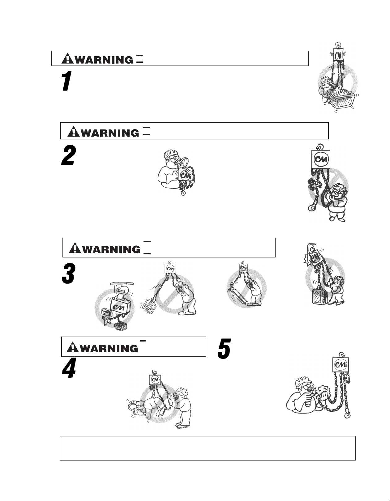
Hoist safety is up to you...
DO NOT LIFT MORE THAN RATED LOAD.
DO OPERATE WITH MANUAL POWER ONLY (ONE OPERATOR).
CHOOSE THE RIGHT
HOIST FOR THE JOB...
hoose a hoist with the capacity for the job. Know the
C
capacities of your hoists and the weight of your loads.
hen match them.
T
INSPECT
All hoists should be visually inspected
before use, in addition to regular, periodic
aintenance inspections.
m
Inspect hoists for operations warning
notices and legibility.
Deficiencies should be noted and brought
to the attention of supervisors. Be sure
efective hoists are tagged and taken out
d
of service until repairs are made.
Under no circumstances should you
perate a malfunctioning hoist.
o
Check for gouged, twisted, distorted
links and foreign material. Do not operate
hoists with twisted, kinked, or damaged
chain links.
The application, the size and type of
oad, the attachments to be used
l
nd the period of use must also be
a
taken into consideration in selecting
the right hoist for the job.
DO NOT OPERATE DAMAGED OR MALFUNCTIONING HOIST.
DO NOT OPERATE WITH TWISTED, KINKED, OR DAMAGED CHAIN.
oad chain should be properly lubricated.
L
ooks that are bent, worn, or whose
H
openings are enlarged beyond normal
hroat opening should not be used. If
t
latch does not engage throat opening of
hook, hoist should be taken out of service.
Chains should be checked for deposits of
foreign material which may be carried into
he hoist mechanism.
t
Check brake for evidence of slippage
under load.
DO NOT PULL AT AN ANGLE. BE SURE HOIST
AND LOAD ARE IN A STRAIGHT LINE.
DO NOT USE LOAD CHAIN AS A SLING.
Remember, the hoist was designed to
ease our burden and carelessness not
nly endangers the operator, but in
o
many cases, a valuable load.
USE HOIST
PROPERLY
Be sure hoist is
solidly held in the
uppermost part of
the support hook arc.
PRACTICE CAUTION ALWAYS
Do not lift co-workers with
a hoist.
Make sure everyone is clear
of the load when you lift.
Do not remove or obscure
operational warning notices.
Be sure hoist and load are in a
straight line. Do not pull at an angle.
DO NOT LIFT PEOPLE
OR LOADS OVER
PEOPLE
Be sure load is hooked securely. Do not
tip load the hook. Do not load hook latch.
Hook latch is to prevent detachment of
load under slack chain conditions only.
OPERATOR
SERVICE
CLEANING
Hoists should be kept clean and free
of dust, dirt, moisture, etc., which will
in any way affect the operation or
safety of the equipment.
LUBRICATION
Chain should be properly lubricated.
AFTER REPAIRS
Carefully operate the hoist before
returning it to full service.
Do not operate with hoist head
resting against any object. Lift the
load gently. Do not jerk it.
VIOLATIONS OF ANY OF THE WARNINGS LISTED MAY RESULT IN SERIOUS PERSONAL INJURY
TO THE OPERATOR OR NEARBY PERSONNEL BY NATURE OF RELEASED LOAD OR BROKEN
HOIST COMPONENTS.
3 i
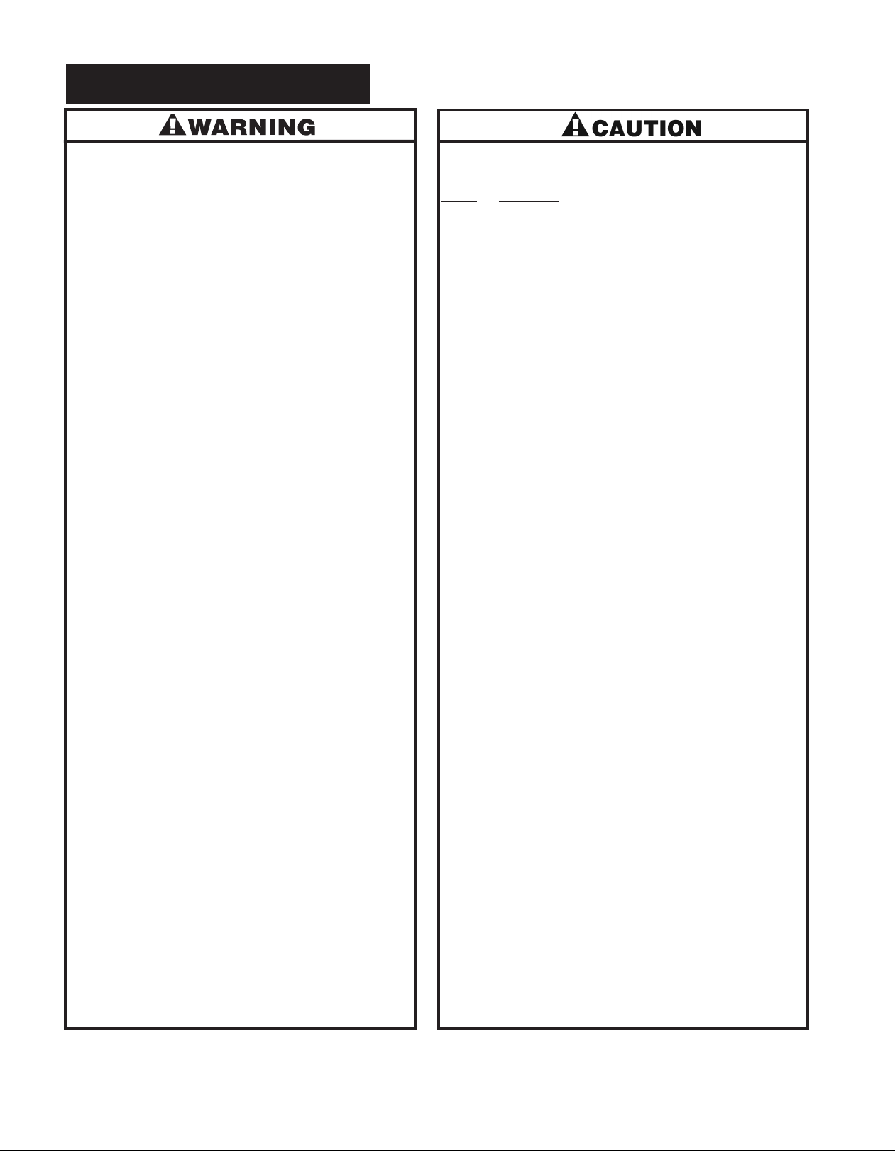
GENERAL SAFETY INFORMATION
!!
Improper operation of a hoist can create a potentially
hazardous situation which, if not avoided, could result
in death, or serious injury. To avoid such a potentially
azardous situation, the operator shall:
h
1. NOT operate a malfunctioning or unusually performing hoist.
. NOT operate the hoist until you have thoroughly read
2
and understood this manual.
3. NOT operate a hoist which has been modified.
4. NOT lift or pull more than rated load for the hoist.
5. NOT use damaged hoist or hoist that is Not working properly.
6. NOT use hoist with twisted, kinked, damaged, or worn
load chain.
7. NOT use the hoist to lift, support, or transport people.
8. NOT lift loads over people and make sure all personnel
remain clear of the supported load.
9. NOT attempt to lengthen the load chain or repair damaged
load chain.
10. Protect the hoists load chain from weld splatter or other
damaging contaminants.
11. NOT use load chain as a sling or wrap load chain around load.
12. NOT apply the load to the tip of the hook or to the
hook latch.
13. NOT apply load unless load chain is properly seated in
the chain wheel(s) or sproket(s).
14. NOT apply load if bearing prevents equal loading on all
load supporting chains.
15. NOT operate beyond the limits of the load chain travel.
16. NOT leave load supported by the hoist unattended
unless specific precautions have been taken.
17. NOT allow the chain or hook to be used as an electrical
or welding ground.
18. NOT allow the chain or hook to be touched by a live
welding electrode.
19. NOT remove or obscure the warnings on the hoist.
20. NOT operate a hoist which has Not been securely
attached to a suitable support.
21. NOT operate a hoist unless load slings or other approved
single attachments are properly sized and seated in the
hook saddle.
22. NOT operate a hoist when it is restricted from forming a
straight line from hook to hook in the direction of loading.
23. NOT lift loads that are Not balanced and that the holding
action is Not secure, taking up slack carefully.
24. NOT operate a hoist unless all persons are and remain
clear of the supported load.
25. Report malfunctions or unusual performances of a hoist,
after it has been shut down until repaired.
26. NOT operate a hoist on which the safety placards or
decals are missing or illegible.
27. Be familiar with operating controls, procedures and warnings.
!! !
Improper operation of a hoist can create a potentially
hazardous situation which, if not avoided, could result in
minor or moderate injury. To avoid such a potentially
hazardous situation, the operator shall:
1. Maintain a firm footing or be otherwise secured when
operating the hoist.
2. Check brake function by tensioning the hoist prior to each
lift or pulling operation.
3. Use hook latches. Latches are to retain slings, chains, etc.
under slack conditions only.
4. Make sure the hook latches are closed and not supporting
any parts of the load.
5. Make sure the load is free to move and will clear all
obstructions.
6. Avoid swinging the load or hook.
7. Inspect the hoist regularly, replace damaged or worn parts,
and keep appropriate records of maintenance.
8. Use only Columbus McKinnon parts when repairing the unit.
9. Lubricate load chain as recommended in this manual.
10. NOT operate except with manual power.
11. NOT permit more than one operator to pull on a single
hand chain at the same time. More than one operator is
likely to cause hoist overload.
12. NOT allow your attention to be diverted from operating
the hoist.
13. NOT allow the hoist to be subjected to sharp contact with
other hoists, structures, or objects through misuse.
14. NOT adjust or repair the hoist unless qualified to perform
such adjustments or repairs.
he hoists are intended for general industrial use for
T
moving loads within their load ratings. Prior to installation
and operation, the user should review the application for
abnormal environmental or handling conditions.
ADVERSE ENVIRONMENTAL CONDITIONS
Do not use the hoists in areas containing flammable vapors,
liquids, gasses or any combustible dust or fibers. Do not use
the hoist in highly corrosive, abrasive, wet environments
or in applications involving exposure to temperatures below
-10 or above 130
MOVING HAZARDOUS LOADS
The hoists are not recommended for lifting materials that could
cause widespread damage if dropped. The lifting or moving
of materials that could explode or cause chemical or radioactive
contamination requires fail-safe, redundant supporting devices
that are not incorporated into these hoists.
o
F.
ii
4
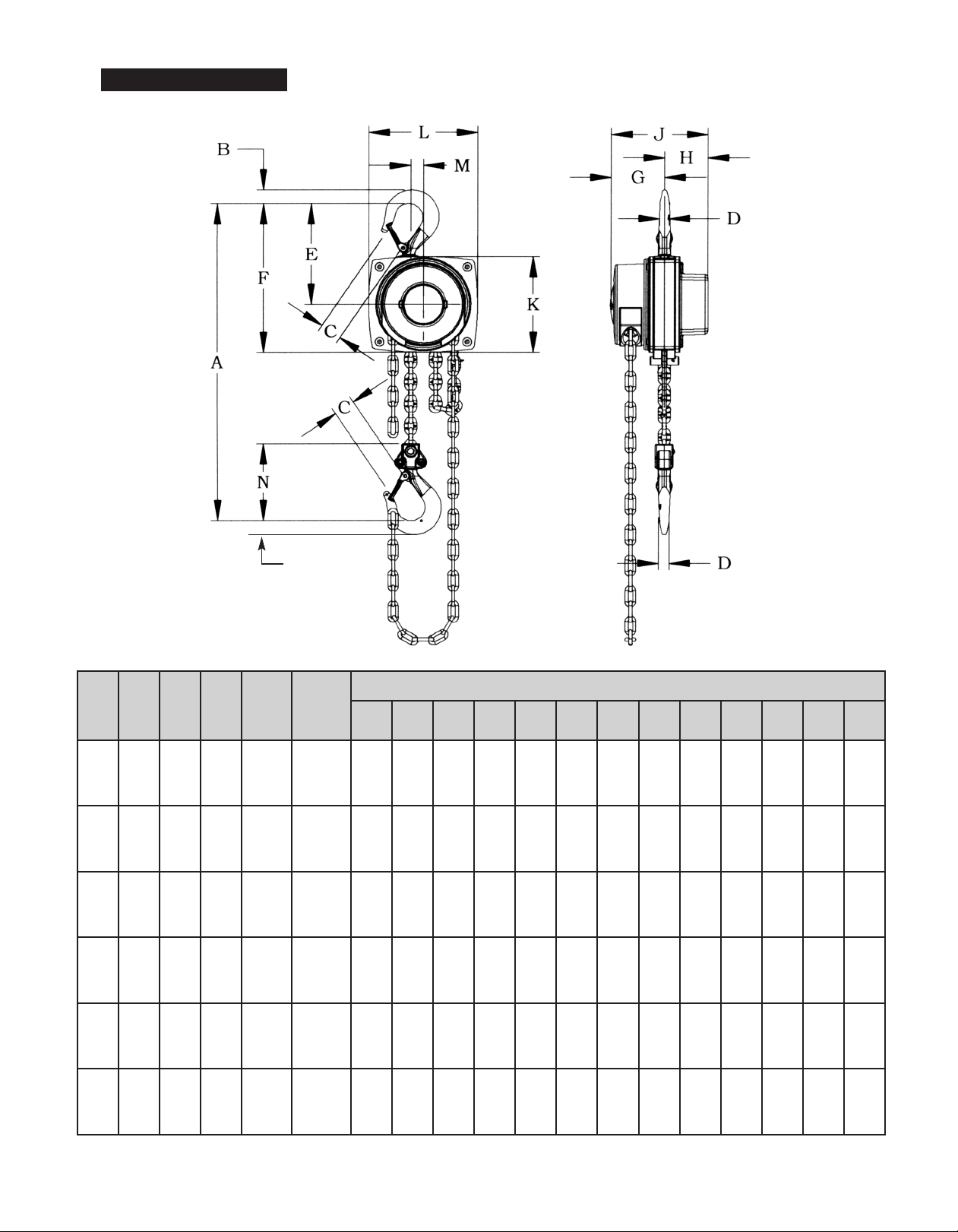
SPECIFICATIONS
Product
Code
5623A
5624A
5625A
5626A
5627A
5628A
5629A
5630A
5631A
5635A
5636A
5637A
Load
Rating
(Tonne)
1/21015
1
2
3
Lift
(ft.)
20
10
15
20
10
15
20
10
15
20
Net
Weight
(lbs.)
20
21
23
29
31
34
44
49
53
64
71
78
B
Hand
Chain Pull
Hand Chain
Overhauled
to Lift
to Lift Load
Rated
One Foot
Load
(lbs.)
44 30 11 13/16 11/16 15/16 9/16 5 1/2 8 1/8 3 3/8 2 3/8 5 13/16 5 1/4 5 13/16 15/16 4 5/16
54 49 13 3/16 7/8 1 1/8 3/4 6 7/16 9 1/2 3 7/8 2 3/4 6 5/8 6 1/8 6 7/8 15/16 4 15/16
74 71 15 9/16 1 3/16 1 3/8 7/8 7 9/16 11 1/8 4 3/8 3 1/4 7 5/8 7 3/16 8 1 1/4 6 1/8
92 87 20 1/2 1 1/2 1 9/16 1 3/16 8 7/8 13 3/16 4 7/8 3 3/4 8 5/8 8 11/16 9 13/16 1 5/16 7
(ft.)
A B C D E F G H J K L M N
Dimensions (in)
5639A
5640A
5641A
5643A
5644A
5645A
10
5
10
84
15
98
20
113
10
157
15
178
20
200
76 174 25 3/4 1 3/4 1 7/8 1 7/16 9 1/2 13 7/8 4 7/8 3 3/4 8 5/8 8 11/16 9 13/16 13/16 11 1/4
102 261 32 1/2 2 11/16 2 11/16 1 15/16 12 13/16 17 3/16 4 7/8 3 3/4 8 5/8 8 11/16 15 1/16 5 3/8 15 13/16
Figure 1 - Specifications
5
1
GENERAL INFORMATION
CM®Hurricane 360 hand operated chain hoists are highly
versatile materials handling equipment that can be used
to effectively lift loads. The frame and covers are made from steel
stampings. Internal gears are made of high grade, heat treated
steel. Shielded ball bearings or bushings support the heat
treated steel liftwheel. Latch type, forged steel upper and
lower hooks are standard. A dry type friction brake that
oes not include pawls and ratchet found in similar hoists
d
provides positive load control and will suspend the load
at any point.
Hoists with load ratings of 1/2, 1, 2, 3, 5 and 10 ton are available
and this manual applies to all of these units. Standard lifts
are 10, 15 and 20 feet and hoists with longer lifts are available
on a special, per order basis. Plated steel hand chain is provided with a drop that is 2 feet less than the lift of the hoist.
®
Hurricane 360 hand operated hoists are built in accor-
CM
dance with the specifications contained herein and at the time
of manufacture complies with our interpretation of the American
Society of Mechanical Engineers (ASME) Standard B30.16,
“Overhead Hoists.” Copies of this standard can be obtained
from ASME Order Department,
22 Law Drive, Box 2300, Fairfield, NJ 07007-2300, USA.
This manual contains important information to help you properly
install, operate and maintain your CM
for maximum performance, economy and safety.
Please study its contents thoroughly before putting your hoist
into operation. By practicing correct operating procedures
and by carrying out the recommended preventive maintenance
suggestions, you will be assured of long, dependable
and safe service.
®
Hurricane 360 Hoist
UNPACKING
After opening the carton, the hoist should be carefully inspected
for damage which may have occurred during shipment
or handling. Check the hoist frame for dents or cracks
and inspect the load chain for nicks and gouges. If shipping
damage has occurred, refer to the packing list envelope
on the carton for claim procedure.
Operating a unit with obvious external damage may cause
load to drop and that may result in personal injury and/or
property damage.
TO AVOID INJURY:
Carefully check unit for external damage prior to installation.
INSTALLATION
Before installing the hoist:
1. Determine the weight of the load that is to be lifted
or moved and make sure it does not exceed the rated load
of the hoist.
2. Make sure the support or sling to which the upper hook
is attached is strong enough to hold several times the weight
of the load to be lifted or moved. Be sure the hoist is solidly
held in the uppermost part of the upper hook and the latch
is closed and not in contact with the support or sling.
After you have completely familiarized yourself with the contents
of this manual, we recommend that you carefully file
it for future reference.
CM®REPAIR/REPLACEMENT POLICY
All Columbus McKinnon (CM®) Hurricane 360 Hoists are inspected
and performance tested prior to shipment. If any properly
maintained hoist develops a performance problem, within one
one year of shipment, due to a material or workmanship defect,
as verified by CM, repair or replacement of the unit will be made
to the original purchaser without charge. This repair/ replacement
policy applies only to CM
maintained and operated as outlined in this manual, and specifically excludes hoists subject to normal wear, abuse, improper
installation, improper or inadequate maintenance, hostile
environmental effects and unauthorized repairs/modifications.
We reserve the right to change materials or design if, in our
opinion, such changes will improve our product. Abuse, repair
by an unauthorized person, or use of non-CM
parts voids the guarantee and could lead to dangerous operation. For full Terms of Sale, see Sales Order Acknowledgement.
Also, refer to the back cover for Limitations of Warranties,
Remedies and Damages, and Indemnification and Safe
Operation.
®
Hurricane 360 Hoists installed,
®
replacement
Attaching the hoist to an inadequate support may allow the
hoist and load to fall and cause injury and/or property damage.
TO AVOID INJURY:
Make sure the structure has sufficient strength to hold
several times the hoist and its rated load.
3. The area in which the hoist is installed must provide
sufficient room for:
-The operator to operate the hand chain.
-The operator and other personnel to stand clear
of the load at all times.
- Firm footing for the operator.
- Clearance between the hoist frame and any object.
-The frame to be free to swivel on the upper hook.
62
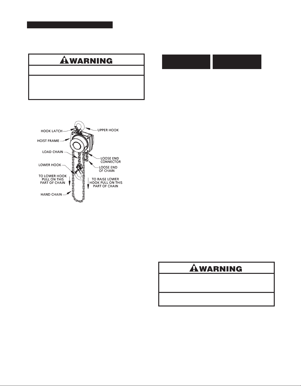
OPERATING INSTRUCTIONS
After mounting and before placing in service, check the hoist
or proper operation. To operate the hoist, pull on the hand
f
chain as indicated below.
If not used as directed, hoist may cause injury.
TO AVOID INJURY:
se only as directed below. Read all instructions before
U
operating the CM
®
Hurricane 360 Hoist.
4. Do not load beyond the rated capacity of the hoist.
ated capacity can be achieved with the following
R
hand chain pulls:
Hoist
Rated Load
(Tons)
/2
1
1
2
3
5
10
Hand Chain Pull
To Lift Rated Load
(Lbs.)
4
4
4
5
74
92
6
7
02
1
Since these hand chain pulls can easily be applied by one person,
under no circumstances should more than one person operate
the hoist hand chain.
This hoist is equipped with a load limiting device. The presence
of this device does not authorize the application of overloads.
Always select a hoist whose load rating is in excess of the load
to be handled. If the handwheel slips while operating, reduce
load or use correct capacity hoist.
NOTE:
The load limiting device incorporated in this hoist is effective
only when the overload is being lifted or pulled through
the operation of the handwheel. It will not protect against
externally applied overloads.
5. Do not wrap load chain around the load or bring the
load in contact with the hoist. Doing this will result
in the loss of the swivel effect of the hook which could
mean twisted chain and a jammed liftwheel. The chain
could be damaged at the hook.
Figure 2 - Main Parts of Hurricane 360 Hoist
Operate the hoist with no load and then a light load of approximately 50 pounds to make sure it operates properly and the
brake holds the load when the hand chain is released, then
6. Stand clear of all loads and avoid moving a load over
the heads of other personnel. Warn personnel of your
intention to move a load in their area.
7. Do not leave the load in the air unattended.
operate with a rated load as shown on the nameplate.
8. Do not lower the hook to a point where the chain
GENERAL
1. The hoist must always be rigged to lift in a straight
becomes taut between the liftwheel and loose end
connector.
line from hook to hook. The hoist must always be free
to swivel on the upper hook. Under no condition should
the hoist frame be allowed to bear on any support when
in use, as this would cause bending of the hook or frame
and damage the unit.
2. When preparing to lift or move a load, be sure that
the attachments to both hooks are firmly seated
in the saddles of the hooks. Avoid off center loading
of any kind especially loading on the tip of the hook.
Also, observe that the chain hangs straight (without twist)
from hoist to lower hook.
3. When lifting, raise the load only enough to clear the floor
or support, and check to be sure brake will hold load
and that attachments to the load are firmly seated.
Continue the lift only after you are assured the load
is free of all obstructions.
Power operation may result in structural damage or premature wear that may cause a part to break and allow the
load to fall.
TO AVOID INJURY:
Operate CM
®
Hurricane 360 Hoists using hand power only.
9. Do not run the lower hook block into the hoist frame.
Frame and/or chain guide damage may result.
10. The hoist has been designed for manual operation only.
11. Do not use this or any other overhead materials handling
equipment for lifting persons.
12. Do not allow the load to bear against the hook latch.
The latch is to help maintain the hook in position while
the chain is slack before taking up slack chain.
7 3
llowing the load to bear against the hook latch
A
and/or hook tip can result in loss of load.
TO AVOID INJURY:
Do not allow the load to bear against the hook latch
and/or hook tip. Apply load to hook bowl or saddle only.
13. Never operate the hoist when flammable materials
or vapors are present. Sharp contact between metal parts
can produce sparks that can cause a fire or explosion.
14. STAY ALERT! Watch what you are doing and use common
sense. Do not use the hoist when you are tired, distracted
or under the influence of drugs, alcohol or medication
causing diminished control.
MAINTENANCE
INSPECTION
To maintain continuous and satisfactory operation, a regular
inspection procedure must be initiated so that worn or damaged
parts can be replaced before they become unsafe. The intervals
of inspection must be determined by the individual application
and are based upon the type of service to which the hoist will
be subjected. The inspection of hoists is divided into two general
classifications designated as “frequent” and “periodic.”
Frequent Inspections:
These inspections are visual examinations by the operator
or other designated personnel. The frequent inspections
are to be performed daily and shall include the following items:
a. Braking mechanisms for evidence of slippage daily.
b. Load Chain for lubricant, wear, damaged links
or foreign material-daily (See LOAD CHAIN, page 5).
Any deficiencies noted are to be corrected before the hoist
is returned to service.
e. Inspect brake components for worn, glazed or con-
taminated brake disc and scoring of the brake hub
and brake plate. If the thickness of the friction
washer is less than 1/32 inch, it should be replaced.
. Replace missing or damaged warning labels.
f
. Corroded, stretched or broken brake spring.
g
h. Hooks-dye penetrant, magnetic particle or other
suitable crack-detecting inspections should be performed at least once a year, if external conditions
indicate there has been unusual usage.
Any deficiencies noted are to be corrected before the hoist
is returned to service. Also, the external conditions may show
the need for more detailed inspection which, in turn, may require
the use of nondestructive-type testing.
Any parts that are deemed unserviceable are to be replaced
®
with new CM
parts before the unit is returned to service.
It is very important that the unserviceable parts be destroyed
to prevent possible future use as a repair item and properly
disposed of.
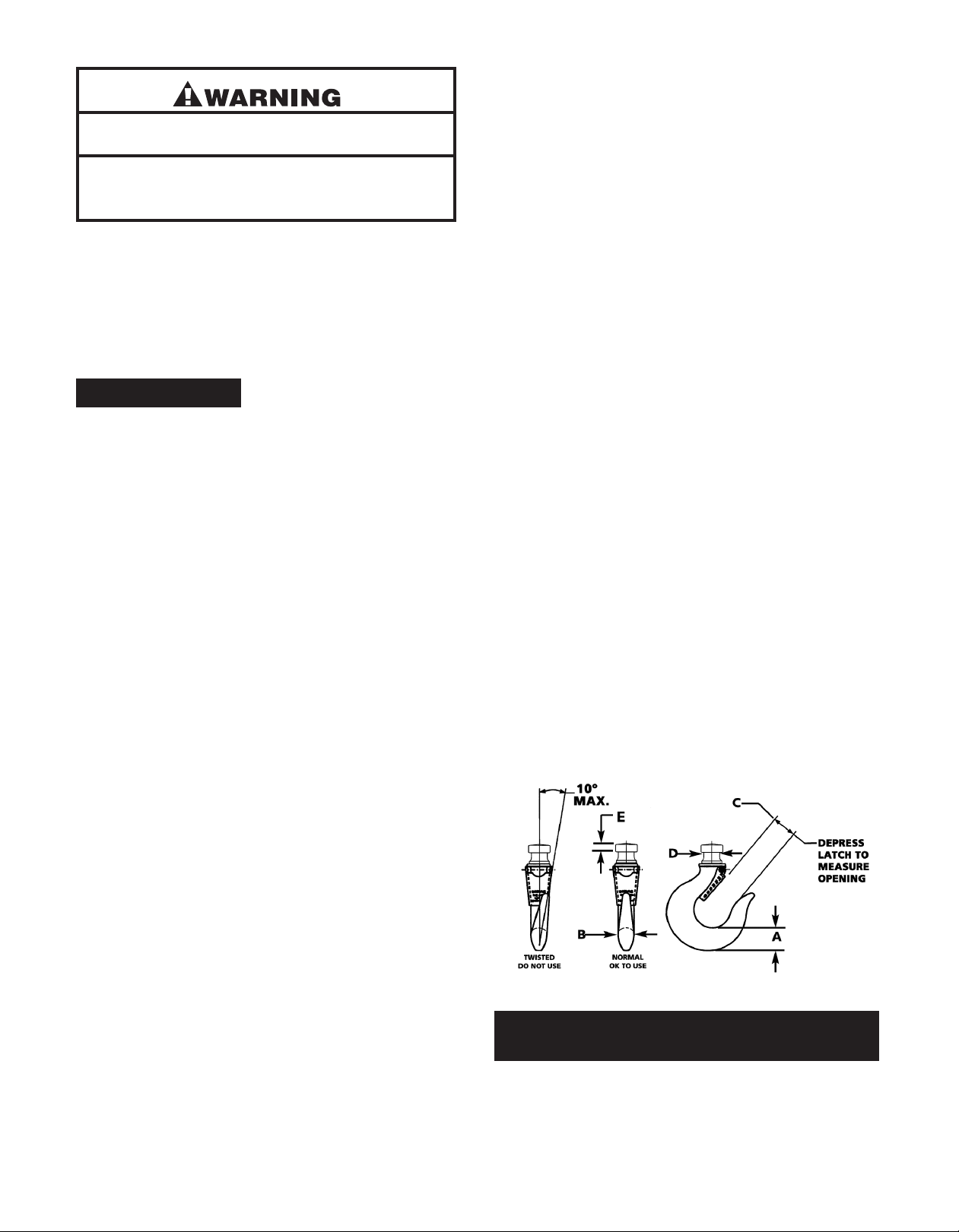
Hook Inspection
Hooks damaged from chemicals, deformation or cracks,
or that have more than a 10otwist from the plane of the
unbent hook, excessive opening or seat wear, must be
replaced. Also, hooks that are opened to the extent that
the latch does not engage the tip must be replaced.
Any hook that is twisted or has excessive throat opening
indicated abuse or overloading of the hoist. Other load
sustaining parts should be inspected for damage.
Check to assure the latch is not damaged or bent and that
it operates properly. It should have sufficient spring pressure
to keep it tightly against the tip of the hook and allow
it to spring back to the tip when released. If the latch does
4not operate properly, replace the latch.
Replace hook if opening is greater than “C” or if the thickness
Periodic Inspections:
These are inspections by an appointed person who makes
records of apparent external conditions to provide the basis
for a continuing evaluation. For normal service, the periodic
inspections are to be performed yearly and for heavy service,
the periodic inspections are to be performed semi-annually.
Due to the construction of the hoist, it will be necessary
to partially disassemble the unit to perform the periodic
inspections. The periodic inspections are to include those items
listed under frequent inspections as well as the following:
a. Chain for excessive wear or stretch (See page 5).
b. Worn, cracked or distorted parts such as hook
blocks, hand chain guides, chain guide, stripper,
loose end connector, shafts, gears, bushings
and bearings.
c. Inspect for wear on the tip of the driver, stops on
handwheel and pockets of the liftwheel and handwheel.
d. Loose or missing screws, nuts, pins or cotter pins.
Figure 3 - Hook Inspection
Hoist Critical Hook Dimensions (in.)
Capacity
(tons) ABCD E
1/2 0.602 0.496 1.039 0.390 0.213
1 0.780 0.673 1.256 0.531 0.230
2 1.063 0.780 1.516 0.670 0.319
3 1.346 1.063 1.732 0.769 0.349
5 1.594 1.311 2.035 1.102 0.472
10 2.409 1.772 2.945 1.378 0.669
84
at “A”, “B”, “D”, or “E” is less than the dimensions listed
in the chart (see Figure 3, page 4).
LOAD CHAIN
Chain should feed smoothly into and away from the hoist.
If chain binds, jumps or is noisy, first clean and lubricate it (See
below). If trouble persists, inspect chain and mating parts
or wear, distortion or other damage.
f
Chain Inspection
Using other than CM®supplied load chain may cause the
chain to jam in the hoist and/or allow the chain
to break and the load to drop.
TO AVOID INJURY:
Due to size requirements and physical properties, use
only CM
®
supplied load chain in the the CM®Hurricane
360 Hoist.
First clean chain with a non-caustic/non-acid type solvent and
make a link by link inspection for nicks, gouges, twisted links,
weld spatter, corrosion pits, striations (minute parallel lines),
cracks in weld areas, wear and stretching. Chain with any one
of these defects must be replaced.
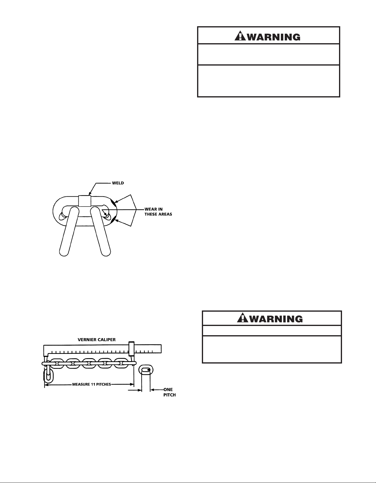
Figure 4 - Chain Inspection
Slack the portion of the chain that normally passes over the liftwheel. Examine the interlink area for the point of maximum wear
(polishing). Measure and record the stock diameter at this point
of the link. Then measure stock diameter in the same area on the
link that does not pass over the liftwheel (use the link adjacent
to the loose end connector for this purpose). Compare these
two measurements. If the stock diameter of the worn link
is 0.010 inch, or more, less than the stock diameter of the unworn
link, the chain must be replaced.
Figure 5 - Chain Inspection
Also check chain for stretch and wear using a vernier caliper
as shown in Figure 5. Select an unused, unstretched section
Worn chain can be an indication of worn hoist components.
For this reason, the hoist’s chain guide, stripper and liftwheel
should be examined for wear and replaced as necessary when
replacing worn chain (See DISASSEMBLY and ASSEMBLY,
page 6).
Also, the load chain is specially heat treated and hardened
and should never be repaired.
IMPORTANT: Do not use replaced chain for other purposes
such as lifting or pulling. Load chain may break suddenly without visual deformation. For this reason, cut replaced chain into
short lengths to prevent use and then dispose of it.
NOTE: The above method of inspecting load chain can also
be used to inspect the hand chain for stretch and wear.
Chain Lubrication
A small amount of lubricant will greatly increase the life of load
chain. Do not allow the chain to run dry. Keep it clean and
lubricate at regular intervals with Lubriplate
10-R (Fiske Bros. Refining Co.) or equal lubricant. Normally,
weekly lubrication and cleaning is satisfactory,
but under hot and dirty conditions, it may be necessary
to clean the chain at least once a day and lubricate it several
times between cleanings .
When lubricating the chain, apply sufficient lubricant to obtain
natural run-off and full coverage, especially in the interlink area.
Used motor oils contain known carcinogenic materials.
®
Bar and Chain Oil
Never use used motor oils as a chain lubricant. Only use
Lubriplate
®
Bar and Chain Oil 10-R as a lubricant for the load
chain.
LUBRICATION
TO AVOID INJURY:
Hoist normally requires no additional lubrication except when
it had been disassembled for cleaning or repairs.
of chain (usually at the loose end) and measure and record the
length over 11 chain links (pitches). Measure and record the
same length on a worn section of chain. If the result (amount
of stretch and wear) is greater than 0.145 inch, the chain must
be replaced.
Use only a “Knife-Edge” caliper to eliminate the possibility
IMPORTANT: Brake is designed to operate dry. Do not use
any grease or lubricant on the braking surfaces.
When lubricating parts adjacent to the brake, do not use
an excessive amount of lubricant which could seep onto
the brake surfaces.
of a false reading by not measuring full pitch length.
9 5

Using any grease or lubricant on the braking surfaces
will cause brake slippage and loss of load control
which may result in injury and/or property damage.
TO AVOID INJURY:
Do not use any grease or lubricant on braking surfaces.
The brake is designed to operate dry.
handwheel brake hub (626-22) and replace it if the friction
surface is excessively scored (see Section 3, HANDWHEEL
OVERLOAD CLUTCH ASSEMBLY). Slide front brake disc
(656-26), ratchet disc assembly (656-21) and rear brake disc
(656-26) from pressure disk (656-20). Remove retaining ring
(656-41) and remove pressure disc (656-20) by turning
counter clockwise. Inspect both brake discs (656-26)
nd replace if excessive wear, scoring, glazing
a
or contamination is found. If brake discs are worn down
to the following thickness, replacement is required:
If hoist is disassembled for service, repair or inspection,
remove and clean existing grease from unit and replace with
approximately 1 oz. of Poliplex 2 (Century Lubricants Co.)
grease or equal lubricant to the exterior surface of the drive
shaft, gears, internal thread of brake hub, surface of liftwheel bushings (1/2 ton unit), bushings in the gear side plate
and gear cover, internal and external surfaces of handwheel
bushings and rim of handwheel cover.
IMPORTANT: To assure long life and top performance,
be sure to lubricate the various parts of the hoist using the
lubricants specified above. If desired, these lubricants can
be purchased from CM
®
(See Figure 8, page 8).
REPLACING LOAD CHAIN
To replace the load chain, remove the lower hook block
(656-17) from the chain. Disconnect the chain from the
loose end connector (656-7) and operate the hoist in the
lowering direction to run the chain out of the hoist.
Feed a length of soft wire up and over the liftwheel.
Attach the wire to the new load chain so that the chain will
be entering the center of the hoist frame. Position the chain
so that the first link to engage the liftwheel is an upstanding
link and the weld on all upstanding links will be away from
the liftwheel. Pull on the wire until the chain engages the liftwheel. Rotate the handwheel until the chain comes out
on the loose side of the hoist. Attach the chain to the loose
end connector and attach the lower hook block assembly
to the chain so that the lower hook is directly below the
upper hook.
Capacity Thickness Min. (in)
1/2 –Ton, 1-Ton & 2-Ton .043
3-Ton, 5-Ton & 10-Ton .063
Inspect ratchet disc assembly (656-21) and pressure disc
(656-20) friction surfaces, replace if excessively scored.
After the brake discs are inspected or replaced, reassemble
the hoist in reverse to the order given above.
2. To inspect or replace the liftwheel, chain guide or stripper,
it is necessary to disassemble the hoist. Remove the load
chain (See REPLACING LOAD CHAIN, above) and then
remove the handwheel cap (656-36) and the handwheel cover
support (656-35). Lift off the handwheel cover (656-34A) and
slide it down the hand chain (656-31). Lift the hand chain out
of the hand wheel (656-27) pockets. Remove cotter pin (656-
33), castle nut (656-30) and washer (656-29) from the drive
shaft (656-10). Remove handwheel overload clutch assembly
by turning handwheel (656-27) counter clockwise. Slide front
brake disc (656-26), ratchet disc assembly (656-21) and rear
brake disc (656-26) from pressure disk (656-20). Remove
retaining ring (656-41) and then remove pressure disc (656-20)
by turning counter clockwise. Remove the handwheel side
plate (656-9), by sliding it over drive shaft (656-10). Remove
the stripper (656-6) and chain guide (656-5). Examine the
stripper, chain guide, liftwheel (656-8) and loose end connector
(656-7) for wear and damage.
DISASSEMBLY AND ASSEMBLY
The parts list and exploded view on pages 12 and 13
show the general arrangement and name of the parts
of the CM
when disassembling and reassembling the hoists so that
all parts are properly installed.
1. To inspect or replace the load brake disc, it is necessary
®
Hurricane 360 Hand Hoist. These should be used
to partially disassemble the hoist. Remove the handwheel
cap (656-36) and the handwheel cover support (656-35).
Lift off the handwheel cover (656-34A) and slide it down
the hand chain (656-31). Lift the hand chain out of the
handwheel (656-27) pockets. Remove cotter pin (656-33),
castle nut (656-30) and washer (656-29) from the drive shaft
(656-10). Remove handwheel overload clutch assembly
by turning handwheel (656-27) counter clockwise. Inspect
If the stripper, chain guide and/or loose end connector are
worn or damaged they should be replaced. If the liftwheel
is not worn or damaged, reassemble the hoist in reverse to
the order given above. If the liftwheel is to be replaced,
continue to disassemble the hoist.
NOTE: Two points of caution to be observed in disassembly and assembly of the gears:
a Loose rollers are used in various locations in some
units. Care must be taken so as to not lose or misplace
these.
b For proper operation, the correct number of rollers
must be installed at the rotating points. Applying
grease to the rollers will help hold them in position during
assembly.
Remove the gear cover (656-1), end covers (656-4) and
gears (656-12A and 656-12B). Remove drive shaft (656-
106

10) by sliding it out and remove locking ring (656-11B).
Remove washer (656-11A) and liftwheel gear (656-11).
Remove the liftwheel (656-8) and replace it. The liftwheel
(656-8) may require pressing out of liftwheel bearings.
Check the gears and other parts for excessive wear, cracks
and distortion. Replace parts as necessary and then
reassemble the unit in reverse to the order in which it was
isassembled. Install the load chain per manual section
d
“REPLACING LOAD CHAIN”, above. After the hoist is completely reassembled, it must be tested for proper operation
(See TESTING, page 8).
3. HANDWHEEL OVERLOAD CLUTCH ASSEMBLY: To inspect
or replace handwheel overload clutch assembly, it is necessary
to partially disassemble the hoist. Remove the handwheel
cap (656-36) and the handwheel cover support (656-35).
Lift off the handwheel cover (656-34A) and slide it down the
hand chain (656-31). Lift the hand chain out of the handwheel
(656-27) pockets. Remove cotter pin (656-33), castle nut (656-
30) and washer (656-29) from the drive shaft (656-10).
Remove handwheel overload clutch assembly by turning
handwheel (656-27) counter clockwise. Use spanner socket
tool (656-45, available from CM Corp.) to remove groove nut
(656-25) from handwheel brake hub (626-22). Slide Belleville
spring washer (656-24), pressure plate (656-23), front brake
disc (656-26), handwheel (656-27) and rear brake disc (656-
26) from handwheel brake hub (626-22). Inspect both brake
discs (656-26) and replace if excessive wear, scoring, glazing
or contamination is found. If brake disc is worn down to the
following thickness, replacement is required:
Capacity Thickness Min. (in)
1/2 –Ton, 1-Ton & 2-Ton .043
3-Ton, 5-Ton & 10-Ton .063
Inspect pressure plate (656-23), handwheel (656-27) and
handwheel brake hub (626-22) friction surfaces, replace
if excessively scored.
Replace parts as necessary and then reassemble the unit
in reverse to the order in which it was disassembled.
Once the handwheel overload clutch is assembled, tighten
the groove nut (656-25) with the spanner socket tool (656-45,
available from CM Corp.) to the following torque specification.
Capacity Torque (in-lb)
1/2 –Ton 31
1-Ton 71
2-Ton 106
3-Ton 128
5-Ton 106
10-Ton 142
These torque value will set the handwheel overload clutch
at approximately 125% of rated capacity. This setting must
be checked with the handwheel overload clutch assembled
into the hoist (See ADJUSTMENT OF LOAD LIMITER).
4. To inspect or replace the pawl or pawl spring, it is necessary
to partially disassemble the hoist. Remove the handwheel cap
(656-36) and the handwheel cover support (656-35). Lift off the
handwheel cover (656-34A) and slide it down the hand chain
(656-31). Lift the hand chain out of the handwheel (656-27)
pockets. Remove cotter pin (656-33), castle nut (656-30) and
washer (656-29) from the drive shaft (656-10). Remove handwheel overload clutch assembly by turning handwheel (656-27)
counter clockwise. Remove retaining ring (656-42), pawl (656-
43), and pawl spring (656-44) from handwheel side plate
assembly (656-9). Inspect pawl (656-43) and pawl spring (656-
43) for wear, replace if worn. Replace parts as necessary and
then reassemble the unit in reverse to the order in which it was
disassembled. After the hoist is completely reassembled,
it must be tested for proper operation (See TESTING, page 8).
5. To replace hook latch, grind off head of rivet and drive it out.
Remove and discard the latch and spring. Attach the new
latch and spring using the roll pin provided in the latch kit.
ADJUSTMENT OF LOAD LIMITER
To adjust the load limiter:
1. Remove the hoist from the supporting structure and lay
it on a flat working surface with the handwheel facing up.
2. Remove the three screws securing the plastic center cap and
remove the cap (656-36) from the handwheel cover (656-34A).
3. Block the load chain by inserting a screwdriver or pin through
the load chain just below the hoist frame. Operate the handwheel in the up direction to remove the slack from the load
chain, closing and locking the brake.
4. Change the adjustment of the load limiter by tightening the
groove nut (656-25) with the spanner socket tool (656-45,
available from CM Corp.) to increase the setting or by loosening
the groove nut (656-25) to decrease the setting.
5. Perform required load tests after adjustment. (See TESTING,
page 8). Revise the adjustment if necessary.
NOTE: The hoist should not be able to lift 150% of the
rated capacity load if the load limiter has been properly
adjusted.
6. Replace the center cap (656-36) in the handwheel cover (656-34A).
LUBRICATION
If hoist is disassembled for service, repair or inspection,
remove and clean existing grease from unit and replace
with approximately 1 oz. of Poliplex 2 (Century Lubricants Co.)
grease or equal lubricant to the exterior surface of the drive
shaft, gears, internal thread of brake hub, surface of liftwheel
bushings (1/2 ton unit), bushings in the gear side plate and gear
cover, internal and external surfaces of handwheel bushings and
rim of handwheel cover.
11 7

Maintenance (Continued)
GEARS
The gears (656-12A and 656-12B)
do not have to be timed and as a result,
they do not have to be oriented
n a certain position during assembly.
i
owever, for proper operation of the
H
1/2, 1, 3, 5 and 10 ton units, one gear
marked “A” and one gear marked “B”
must be used.
PREVENTIVE MAINTENANCE
In addition to the inspection procedures,
a preventative maintenance program
should be established to prolong the
useful life of the hoist and maintain
its dependability and continued safe use.
The program should include the periodic
ITEM REMARKS (LIST DEFICIENCIES AND RECOMMENDED ACTION)
inspections with particular attention
being paid to the lubrication of various
components using the recommended
lubricants (See Figure 8).
TESTING
Prior to initial use, all repaired or used
hoists that have not been operated for
the previous 12 months shall be tested
by the user for proper operation.
Test the unit first in the unloaded state
and then with a light load of 100 lbs.
times the number of load supporting
arts of load chains to be sure it oper-
p
ates properly and the brake holds the
load when the hand chain is released;
then test with a load of 125% of its
rated capacity.
INSPECTOR’S REPORT
In addition, hoists in which load
sustaining parts have been replaced
must be tested with 125% of rated
capacity by or under the direction
of a designated person and a written
report prepared for record purposes.
NOTE: Because this hoist is equipped
with a load limiting device occasional
slipping of the handchain wheel may
occur when testing with 125 percent
of rated load.
NOTE: For additional information
on Inspection and Testing refer to
ASME B30.16,”Overhead Hoists”,
obtainable from ASME Order
Department,
22 Law Drive, Box 2300, Fairfield, NJ
07007-2300, U.S.A.
Inspector’s Date
Signature Inspected Approved by Date
Figure 7 - Recommended Inspector’s Report
RECOMMENDED LUBRICATION SCHEDULE*
KEY NO. COMPONENT TYPE OF LUBRICANT ** ORDER TYPE OF SERVICE AND
(SEE PAGES PART NO. FREQUENCY OF LUBRICATION
(12 & 13) HEAVY NORMAL INFREQUENT
656-28 Load Chain Lubriplate
656-11 Gears and
656-12 Bearing Surfaces 28629 When hoist is disassembled for cleaning
656-13 of Upper Poliplex 2 (1 lb. can) or repairs
656-17 and Lower
Hook Knobs
* This lubrication schedule is based on a hoist operating in normal environment conditions. Hoists operating in adverse
atmospheres containing excessive heat, corrosive fumes or vapors, abrasive dust, etc., should be lubricated more frequently.
** See page 12 for ORDERING INSTRUCTIONS.
®
HURRICANE 360 HAND HOIST
CM
®
Bar and 28619 Daily Weekly Monthly
Chain Oil 10-R (1 gal. can)
Figure 8 - Recommended Lubrication Schedule
128

Maintenance (Continued)
INSPECTION AND MAINTENANCE CHECK LIST
HAND OPERATED HOIST
Type of Hoist ___________________________________________
Location _______________________________________________
Manufacturer __________________________________________
Capacity (Tons) __________________________________________
Original Installation Date ________________________________
Manufacturer’s Serial No. ________________________________
Item Frequency of Inspection Possible Deficiencies OK Action
Frequent Periodic Required
Daily
Every 3 Months
Brake Mechanism **Slippage or excessive drift.
Worn, glazed or contaminated brake discs.
Thickness of friction washer less than 1/32 inch.
Handwheel **Binding and does not move freely.
Load Chain **Inadequate lubrication, excessive wear or stretch,
cracked, damaged or twisted links, corroded or
clogged with foreign material.
Hooks **Excessive throat opening, twisted more than 10°,
damaged or non-operating hook latch, chemical
damage. Cracks (Use dye penetrant, magnetic or
other suitable detection method at least once a year).
Lower Hook Block,Upper Hook * Cracks, distortion, excessive wear, corrosion
Block, Upper Hook Pin, or build-up of foreign material.
Chain Guide, Bushings, Gears,
Drive Shaft, Brake Hub and
Brake Plate
Tip of Driver, Inboard and * Cracks, distortion, excessive wear, corrosion
Outboard Stops on Handwheel or build-up of foreign material.
and Outboard LugsonBrake Hub.
Pockets of Liftwheel, Stripper * Cracks, distortion, excessive wear, corrosion
and Side Plates or build-up of foreign material.
Nuts, Screws, Pins and Cotter Pin * Cracks, bending, loose, stripped threads.
Brake Spring * Corrosion, stretched or broken.
Loose End Connector * Missing, cracked, not secured to chain, not
properly positioned.
Nameplate, Warning Labels * Missing, damagedor illegible.
and Warning Tube
NOTE: Refer to Maintenance and Inspection Sections of this manual for further details.
FREQUENCY OF INSPECTION
Frequent - Indicates items requiring inspection daily or before each use. These inspections may be performed by the operator if properly designated.
Periodic - Indicates items requiring inspection every three months. Inspections to be performed by or under the direction of a properly designated person.
NOTE: This inspection and maintenance check list is in accordance with our interpretation of the requirements of the Safety Standard
applicable requirements of this safety standard.
Figure 9 - Recommended Inspection and Maintenance Check List
The exact period of inspection will depend on frequency and type of usage. Determination of this period will be based on the user’s experience. It
is recommended that the user begin with a quarterly inspection and extend the periods to semi-annually or annually based on the user’s quarterly
experience.
for Overhead Hoists ASME B30.16. It is, however, the ultimate responsibility of the employer/user to interpret and adhere to the
13 9

Troubleshooting Chart
ymptom Possible Cause(s) Corrective Action
S
1. Hoist is hard to
operate in either
direction.
2. Hoist is hard to
operate in the
lowering direction.
A) Load chain worn long to gage, thus binding
between liftwheel and chain guide.
B) Load chain rusty, corroded or clogged with
foreign matter such as cement or mud.
C) Load chain damaged.
D) Liftwheel clogged with foreign matter or worn
excessively, causing binding between the lift-
heel and chain guide.
w
E) Hand chain worn long to gage, thus binding
between handwheel and cover.
F) Handwheel clogged with foreign matter
or worn excessively, causing binding of chain
between the handwheel and cover.
G) Liftwheel or gear teeth deformed.
A) Brake parts corroded or coated with foreign
matter.
B) Brake not properly adjusted.
C) Chain binding.
A) Check gage of chain (See page 5). Replace
if worn excessively.
B) Clean by tumble polishing or using a non-
caustic type solvent. Lubricate with
Lubriplate® Bar and Chain Oil 10-R (Fiske
Bros. Refining Co.) or equal lubricant.
C) Check chain for gouges, nicks, bent
or twisted links. Replace if damaged.
) Clean out pockets. Replace if worn
D
excessively.
E) Check gage of chain (See page 5).
F) Clean out pockets. Replace if worn
excessively.
G) Excessive overload has been applied.
Replace damaged parts.
A) Disassemble brake and clean thoroughly.(By
wiping with a cloth- not by washing in a solvent). Replace brake disc if gummy, visibly
worn or coated with a foreign matter. Keep
brake disc and brake surfaces clean and dry.
B) Readjust Brake (See page 7).
C) See Items 1A, 1B and 1C.
3. Hoist is hard to
operate in the
hoisting direction.
4. Hoist will not operate in
either direction.
5. Hoist will not
operate in the
lowering direction
6. Hoist will not operate in
the hoisting direction.
7. Hoist will not hold load
in suspension.
A) Chain binding.
A) Driver or stops on handwheel broken.
B) Gears jammed.
A) Locked brake due to a suddenly applied load,
shock load, or load removed by means other
than by operating unit in the
lowering direction.
B) Chain binding.
C) Lower hook all the way out. Load Chain fully
extended.
A) Chain binding
B) Overload
A) Lower hook or load side of chain on wrong
side of liftwheel.
B) Brake not properly adjusted.
C) Driver or stops on handwheel broken.
D) Worn brake parts.
E) Oily, dirty or corroded brake friction surfaces.
A) See Items 1A, 1B and 1C.
A) Replace damaged part.
B) Inspect for foreign matter in gear teeth.
A) With hoist under load keep chain taut,
pull sharply on hand chain in the lowering
direction to loosen brake.
B) See Items 1A, 1B and 1C.
C) Chain taut between the liftwheel and loose
end connector. Operate unit in hoisting
direction only.
A) See Items 1A, 1B and 1C.
B) If handwheel slips while operating, reduce
load or use correct capacity hoist.
A) Lower hook must be on same side of liftwheel
as upper hook.
B) Readjust Brake (See page 7).
C) See Item 4A.
D) Replace brake parts which are worn.
E) See Item 2A.
1410

NOTES:
15 11
 Loading...