

Page 1
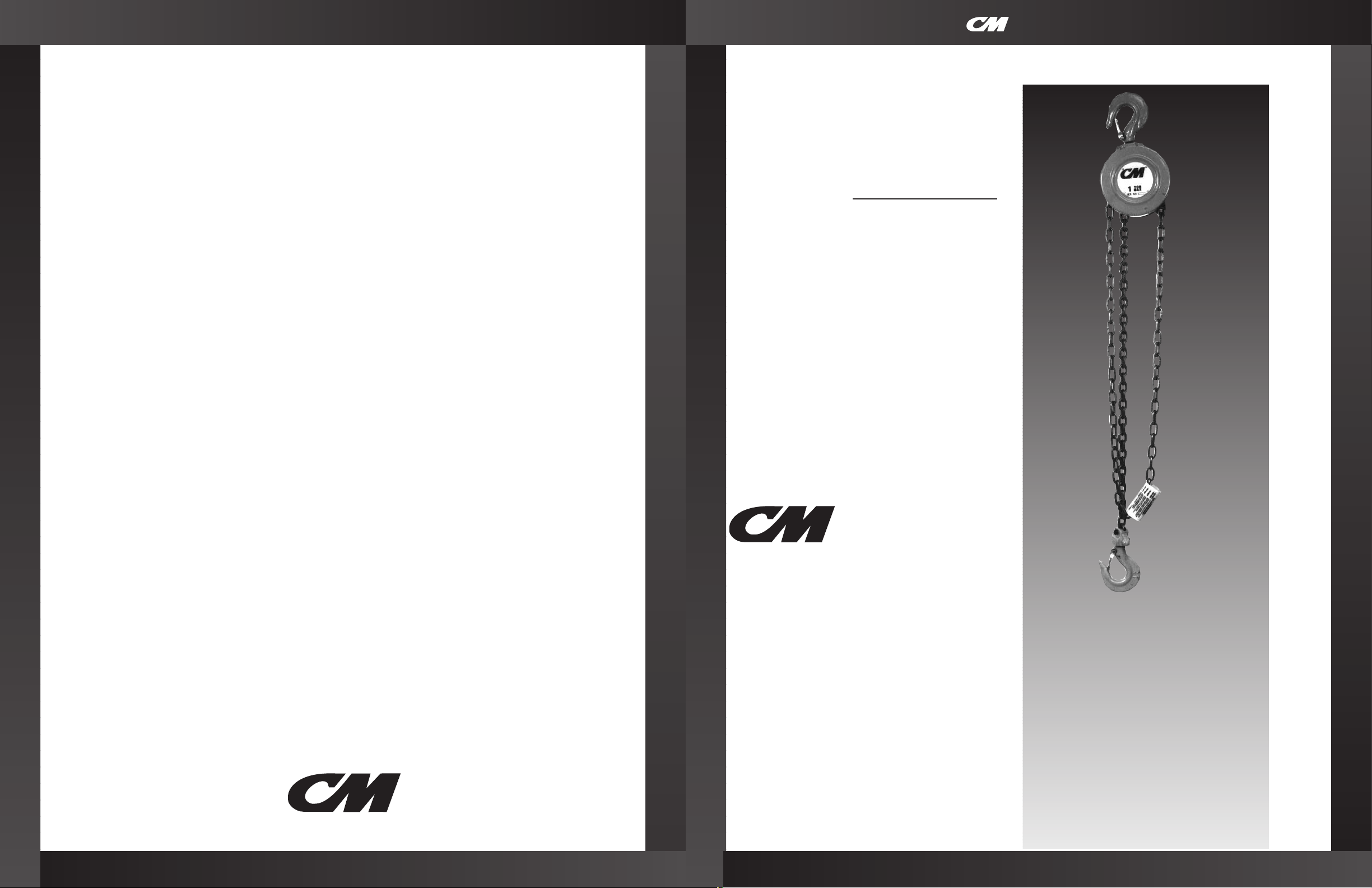
© 1996 Columbus McKinnon Corp. Printed in USA
Note: When ordering parts, always furnish rated load and serial number of hoist on
which the parts are to be used.
For the location of the nearest CM Master Parts Depot, see the list located on the
inside front cover.
Columbus McKinnon Corporation • Industrial Products Division • 140 John James Audubon Parkway
Amherst, New York 14228-1197 • 1-800-888-0985 • Fax 716-689-5644
LIMITATION OF WARRANTIES, REMEDIES AND DAMAGES
THE WARRANTY STATED BELOW IS GIVEN IN PLACE OF ALL
OTHER WARRANTIES, EXPRESS OR IMPLIED, OF
MERCHANTABILITY, FITNESS FOR A PARTICULAR PURPOSE,
OR OTHERWISE, NO PROMISE OR AFFIRMATION OF FACT
MADE BY ANY AGENT OR REPRESENTATIVE OF SELLER
SHALL CONSTITUTE A WARRANTY BY SELLER OR GIVE RISE
TO ANY LIABILITY OR OBLIGATION.
Seller warrants that on the date of delivery to carrier the goods
are free from defects in workmanship and materials.
SELLER’S SOLE OBLIGATION IN THE EVENT OF BREACH OF
WARRANTY OR CONTRACT OR FOR NEGLIGENCE OR
OTHERWISE WITH RESPECT TO GOODS SOLD SHALL BE
EXCLUSIVELY LIMITED TO REPAIR OR REPLACEMENT, F.O.B.
SELLER’S POINT OF SHIPMENT, OF ANY PARTS WHICH
SELLER DETERMINES TO HAVE BEEN DEFECTIVE or if Seller
determines that such repair or replacement is not feasible, to a
refund of the purchase price upon return of the goods to Seller.
Any action against Seller for breach of warranty, negligence or
otherwise, must be commenced within one year after such
cause of action occurs.
NO CLAIM AGAINST SELLER FOR ANY DEFECT IN THE
GOODS SHALL BE VALID OR ENFORCEABLE UNLESS
BUYER’S WRITTEN NOTICE THEREOF IS RECEIVED BY
SELLER WITHIN ONE YEAR FROM THE DATE OF SHIPMENT.
Seller shall not be liable for any damage, injury or loss arising
out of the use of the goods if, prior to such damage, injury or
loss, such goods are (1) damaged or misused following Seller’s
delivery to carrier; (2) not maintained, inspected, or used in
compliance with applicable law and Seller’s written
instructions and recommendations; or (3) installed, repaired,
altered or modified without compliance with such law,
instructions or recommendations.
UNDER NO CIRCUMSTANCES SHALL SELLER BE LIABLE
FOR INCIDENTAL OR CONSEQUENTIAL DAMAGES AS THOSE
TERMS ARE DEFINED IN SECTION 2-715 OF THE UNIFORM
COMMERCIAL CODE.
INDEMNIFICATION AND SAFE OPERATION
Buyer shall comply with and require its employees to comply
with directions set forth in instructions and manuals furnished
by Seller and shall use and require its employees to follow
such instructions and manuals and to use reasonable care in
the use and maintenance of the goods. Buyer shall not remove
or permit anyone to remove any warning or instruction signs
on the goods. In the event of personal injury or damage to
property or business arising from the use of the goods, Buyer
shall within 48 hours thereafter give Seller written notice of
such injury or damage. Buyer shall cooperate with Seller in
investigating any such injury or damage and in the defense of
any claims arising therefrom.
If Buyer fails to comply with this section or if any injury or
damage is caused, in whole or in part, by Buyer’s failure to
comply with applicable federal or state safety requirements,
Buyer shall indemnify and hold Seller harmless against any
claims, loss or expense for injury or damage arising from the
use of the goods.
®
SOLUTIONS
OPERATING,
MAINTENANCE &
PARTS MANUAL
HAND OPERATED
CHAIN HOIST
Price: $5.00 Manual No. B622-B
Before installing hoist, fill in the
information below.
Rated Load __________________
Serial No. ____________________
Purchase Date _______________
22950
®
Rated Loads:
1/2, 1, 2, 3, 5 and 10 tons
(500,1000, 2000, 3000, 5000,
and 10,000kg.)
Follow all instructions and warnings for
inspecting, maintaining and operating this hoist.
The use of any hoist presents some risk of personal
injury or property damage. That risk is greatly
increased if proper instructions and warnings are not
followed. Before using this hoist, each operator
should become thoroughly familiar with all warnings,
instructions and recommendations in this manual.
Retain this manual for future reference and use.
Forward this manual to operator.
Failure to operate equipment as directed
in manual may cause injury.
SERIES 622
SS 1/00
S
eries
622
Page 2

CM HOIST PARTS AND SERVICES ARE AVAILABLE IN THE UNITED STATES AND IN CANADA
As a CM Hoist user, you are assured of reliable repair and parts services through a network of Master Parts Depots and
Service Centers that are strategically located in the United States and Canada. These facilities have been selected on the
basis of their demonstrated ability to handle all parts and repair requirements promptly and efficiently.
Below is a list of the Master Parts Depots in the United States and Canada. To quickly obtain the name of the U.S. Service
Center located nearest you, call (800) 888-0985. Fax: (716) 689-5644. In the following list, the Canadian Service Centers
are indicated.
UNITED STATES
MASTER PARTS DEPOT
ALABAMA
ABB POWER SERVICES
612 32nd Street, South
Birmingham, AL 35233
205/328-5952
Fax 205/251-6759
CALIFORNIA
OTTO SYSTEMS, INC.
12010 Bloomfield Ave.
Santa Fe Springs, CA 90670
310/462-1612
Fax 310/462-1617
or
2439 Verna Court
San Leandro, CA 94577
510/667-3730
Fax 510/667-3726
COLORADO
MATERIALS HANDLING EQUIPMENT CO.
1740 W. 13th Ave.
Denver, CO 80204
303/573-5333
Fax 303/893-3854
FLORIDA
TAMPA ARMATURE WORKS, INC.
440 South 78th Street
Tampa, FL 33619
813/621-5661
Fax 813/622-7040
GEORGIA
ACE INDUSTRIES, INC.
6295 McDonough Drive
Norcross, GA 30093
770/441-0898
Fax 770/441-0326
ILLINOIS
SERVICE ELEVATOR & ELEC. CO.
5819 West Irving Park Rd.
Chicago, IL 60634
312/545-5848
Fax 312/545-8610
TORRANCE ELECTRIC COMPANY
415-31st. Ave.
Rock Island, IL 61204-6008
309/786-7777
Fax 309/786-8705
INDIANA
HORNER ELECTRIC COMPANY, INC.
1521 East Washington St.
Indianapolis, IN 46201
317/ 639-4261
Fax 317/639-4269
LOUISIANA
BEERMAN PRECISION, INC.
4206 Howard Avenue
New Orleans, LA 70125
504/486-9391
Fax 504/486-7482
MASSACHUSETTS
ABEL DISTRIBUTORS, INC.
70 Flagship Drive
N. Andover, MA 01845
508/975-8234
Fax 508/683-7025
MICHIGAN
GAYLORD HOIST SALES & SERVICE
34471 Industrial Road
Livonia, MI 48150
313/261-1910
Fax 313/261-1788
MISSOURI
INDEPENDENT ELECTRIC MACHINERY
310 West 20th Street
Kansas City, MO 64108
816/471-2610
Fax 816/421-3054
NEW JERSEY
LIVELY AND COMPANY
10 Merry Lane
East Hanover, NJ 07936
201/887-6440
Fax 201/887-9586
NEW YORK
VOLLAND ELECTRIC EQUIPMENT CO.
75 Innsbruck Drive
Buffalo, NY 14227
716/656-9900
Fax 716/656-8898, 8899
NORTH CAROLINA
SOUTHERN ELECTRIC SERVICE CO., INC.
2225 Freedom Drive
Charlotte, NC 28208
704/372-4832
Fax 704/342-2604
OHIO
MAZZELLA WIRE ROPE & SLING COMPANY
14600 Brookpark Road
Cleveland, OH 44135
216/362-4600
Fax 216/362-4952
PENNSYLVANIA
AMICK ASSOCIATES, INC.
11 Sycamore Street
Carnegie, PA 15106-0529
412/429-1212
Fax 412/429-0191
RAM INDUSTRIES, INC.
70 Pitney Rd.
Lancaster, PA 17602
717/392-2128
Fax 717/392-2788
TEXAS
ABEL EQUIPMENT CO., INC.
3710 Cavalier Drive
Garland, TX 75042
214/272-7706
Fax 214/272-6955
HYDRAULIC EQUIPMENT SERVICE, INC.
1021 North San Jacinto St.
Houston, TX 77002
713/228-9601
Fax 713/228-0931
WASHINGTON
UNITED ELECTRIC MOTORS
308 9th Ave. North
Seattle, WA 98109
206/624-0044
Fax 206/622-4894
WISCONSIN
TRESTER HOIST & EQUIPMENT, INC.
4465 North 124th St.,Unit B
Brookfield, WI 53005
414/790-0700
Fax 414/790-1009
CANADIAN
SERVICE CENTERS
ALBERTA
**COLUMBUS McKINNON, LTD.
10311-174th Street
Edmonton, Alberta T8H 1N3
NOVA SCOTIA
*W & A MOIR
95 Ilsley Ave.
Dartmouth, Nova Scotia B3B 1L5
902/468-7720
Fax 902/468-3777
ONTARIO
*R & W HOIST REPAIR, LTD.
790 Redwood Square
Units 5, 6, & 7
Oakville, Ontario L6L 6N3
905/825-5500
Fax 905/825-5315
*TORONTO ELECTRIC HOIST
SALES & SERVICE
72 Crockford Blvd.
Scarborough, Ontario M1R 3C4
416/755-7716
Fax 800/461-0290
*MASLACK SUPPLY, LTD.
488 Falconbridge Road
Sudbury, Ontario P3A 4S4
705/566-1270
Fax 705/566-4208
*COLUMBUS MCKINNON, LTD.
P.O. Box 1106
10 Brook Road, North
Cobourg, Ontario K9A 4W5
905/372-0153
Fax 905/372-3078
QUEBEC
*HERCULES SLING & CABLE
2525 Louis A. Amos
Lachine, Quebec H8T 1C3
514/631-5511
Fax 514/636-1084
*LEGER HOIST EQUIPMENT CO.
7995-17th Ave.
Montreal, Quebec H1Z 3R2
514/376-3050
Fax 514/376-0657
* ARE ALSO MASTER PARTS DEPOTS
** MASTER PARTS DEPOT ONLY
1
Page 3
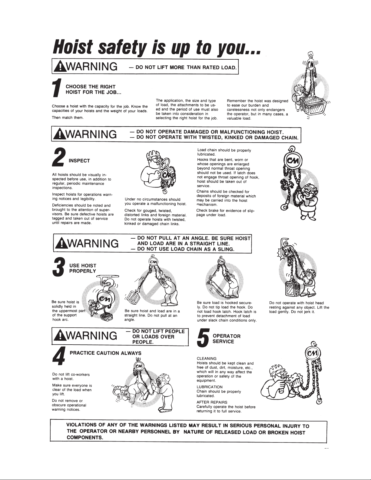
2
Page 4
3
SAFETY PRECAUTIONS
Each Series 622 Hand Hoist is built in accordance with the specifications contained herein and at the time of
manufacture complies with our interpretation of applicable sections of the * American Society of Mechanical
Engineers Code B30.16 “Overhead Hoist” and the Occupation Safety and Health Act.
The safety laws for elevators and for dumbwaiters may specify construction details that are not necessarily
incorporated in CM industrial hoists. We recommend the use of equipment that meets state and national safety
codes. Columbus McKinnon Corporation cannot be responsible for applications other than those for which CM
equipment is recommended.
THIS SYMBOL POINTS OUT IMPORTANT SAFETY INSTRUCTIONS WHICH IF NOT FOLLOWED
COULD ENDANGER THE PERSONAL SAFETY AND/OR PROPERTY OF YOURSELF AND OTHERS. READ AND FOLLOW ALL INSTRUCTIONS IN THIS MANUAL AND ANY PROVIDED WITH
THE EQUIPMENT BEFORE ATTEMPTING TO OPERATE YOUR SERIES 622 HOIST.
Consult Columbus McKinnon Corporation for any usage of Series 622 Hoists that do not involve raising of the load on the lower hook, or
usage of Series 622 Hoists in the inverted position. Using hoists, without special precautions, in such applications may cause an accident
that could result in injury and/or property damage.
* Copies of this standard can be obtained from ASME Order Department, 22 Law Drive, Box 2300, Fairfield, NJ 07007-2300, U.S.A.
DO’S AND DO NOT’S
Safe Operation of Hoists
The following are Do’s and Do Not’s for safe operation of overhead hoists. Taking precedence over
any specific rule listed here, however, is the most
important rule of all, USE COMMON SENSE. A few
minutes spent reading these rules can make an
operator aware of dangerous practices to avoid and
precautions to take for his own safety and the safety of others. Frequent examinations and periodic
inspections of the equipment as well as a conscientious observance of safety rules may save lives as
well as time and money.
WARNING
- To Avoid Injury:
!
13. DO inspect hoist regularly, replace damaged or
worn parts, and keep appropriate records of
maintenance.
14. DO use CM parts when repairing a hoist.
15. DO use hook latches wherever possible.
16. DO apply lubricant to the load chain as recom-
mended in this manual.
17. DO replace damaged or malfunctioning hook
latch.
18. DO NOT lift more than rated load.
19. DO NOT use damaged hoist or hoist that is not
working correctly.
20. DO NOT use the hoist with twisted, kinked,
damaged or worn chain.
21. DO NOT lift a load unless chain is properly
seated in chain wheel(s).
22. DO NOT use load chain as a sling or wrap
chain around the load.
23. DO NOT lift a load if any binding prevents equal
loading on all supporting chains.
24. DO NOT apply the load to the tip of the hook.
25. DO NOT operate unless load is centered under
hoist.
26. DO NOT operate hoist with other than manual
power.
27. DO NOT permit more than one operator to pull
on a single hand chain at one time.
28. DO NOT allow your attention to be diverted
from operating the hoist.
29. DO NOT operate the hoist beyond limits of load
chain travel.
30. DO NOT use hoist to lift, support or transport
people.
31. DO NOT lift loads over people.
32. DO NOT leave a suspended load unattended
unless specific precautions have been taken.
33. DO NOT allow sharp contact between two
hoists or between hoist and obstructions.
34. DO NOT allow the chain or hook to be used as
a ground for welding.
35. DO NOT allow the chain or hook to be touched
by a live welding electrode.
36. DO NOT remove or obscure the warnings on
the hoist.
37. DO NOT adjust or repair a hoist unless qualified
to perform hoist maintenance.
38. DO NOT attempt to lengthen the load chain or
repair damaged load chain.
1. DO read ASME B30.16 Safety Standard for
Overhead Hoists and this manual thoroughly.
2. DO be familiar with hoist operating controls,
procedures and warnings.
3. DO make sure the hoist suspension hook is
securely attached to a suitable support.
4. DO maintain firm footing or be otherwise
secured when operating hoist.
5. DO make sure that load slings or other
approved single attachments are properly sized
and seated in the hook saddle.
6. DO make sure that the hook latch, if used, is
closed and not supporting any part of the load.
7. DO make sure that load is free to move and will
clear all obstructions.
8. DO take up slack chain carefully, check load
balance, lift a few inches (centimeters) and
check load holding action before continuing.
9. DO make sure that all persons stay clear of the
suspended load.
10. DO avoid swinging of load or load hook.
11. DO protect load chain from weld spatter or
other damaging contaminants.
12. DO promptly report any malfunction, unusual
performance, or damage of the hoist.
!
!
Page 5
OPERATING INSTRUCTIONS
4
This manual contains important information to help you properly install, operate and
maintain your Series 622 Hoist for maximum performance, economy and safety.
Please study its contents thoroughly before putting your hoist into operation. By
practicing correct operating procedures and by carrying out the recommended preventive maintenance suggestions, you will be assured of long, dependable and safe
service.
After you have completely familiarized yourself with the contents of this manual, we
recommend that you carefully file it for future reference.
The information herein is directed to the proper use, care and maintenance of the
Series 622 Hoist and does not comprise a handbook on the broad subject of rigging.
Rigging can be defined as the process of lifting and moving heavy loads using hoists
and other mechanical equipment. Skill acquired through specialized experience and
study is essential to safe rigging operations. For rigging information, we recommend
consulting a standard textbook on the subject.
CM REPAIR/REPLACEMENT POLICY
All Columbus McKinnon (CM) Series 622 Hoists are inspected and performance tested prior to shipment. If any properly maintained hoist develops a performance problem, within one year of shipment, due to a material or workmanship defect, as verified
by CM, repair or replacement of the unit will be made to the original purchaser without charge. This repair/replacement policy applies only to Series 622 Hoists installed,
maintained and operated as outlined in this manual, and specifically excludes hoists
subject to normal wear, abuse, improper installation, improper or inadequate maintenance, hostile environmental effects and unauthorized repairs/modifications.
We reserve the right to change materials or design if, in our opinion, such changes
will improve our product. Abuse, repair by an unauthorized person, or use of non-CM
replacement parts voids the guarantee and could lead to dangerous operation. For
full Terms of Sale, see Sales Order Acknowledg-ment. Also, refer to the back cover
for Limitations of Warranties, Remedies and Damages, and Indemnification and Safe
Operation.
UNPACKING
After opening the carton, the hoist should be carefully inspected for damage which
may have occurred during shipment or handling. Check the hoist frame for dents or
cracks and inspect the load chain for nicks and gouges. If shipping damage has
occurred, refer to the packing list envelope on the carton for claim procedure.
WARNING
Operating a unit with obvious external damage may cause load to drop and
that may result in personal injury and/or property damage.
TO AVOID INJURY:
Carefully check unit for external damage prior to installation.
SAFETY PROCEDURES
1. The hoist must always be rigged to lift in a straight line from hook to hook. The
hoist must always be free to swivel on the upper hook. Under no condition
should the hoist frame be allowed to bear on any support when in use as this
would cause bending of the hook or frame and damage the unit.
2. When preparing to lift or move a load, be sure that the attachments to both
hooks are firmly seated in the saddles of the hooks. Avoid off center loading of
any kind especially loading on the tip of the hook. Also observe that the chain
hangs straight (without twist) from hoist to lower hook.
3. When lifting, raise the load only enough to clear the floor or support, and check
to be sure brake will hold load and that attachments to the load are firmly
seated. Continue the lift only after you are assured the load is free of all
obstructions.
4. Do not load beyond the rated capacity of the hoist. Rated capacity can be
achieved with the following hand chain pulls:
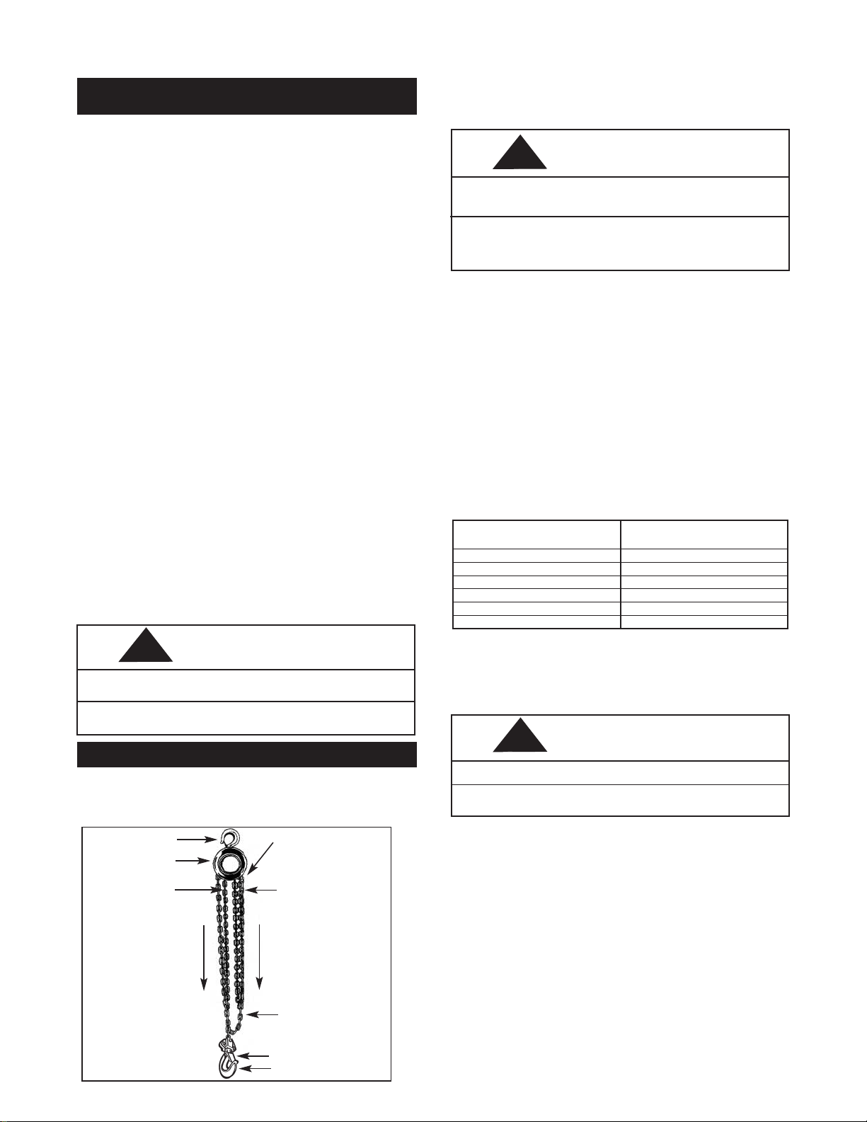
Loose End
Pin
Upper Hook
Hoist Frame
Load Chain
Hand Chain
Loose End
of Chain
Hook Latch
Lower Hook
To Raise Hook
Pull On This
Part of
Hand Chain
To Lower
Hook
Pull On This
Part of
Hand Chain
After mounting and before placing in service, check the hoist for proper operation.
Before operating the 3, 5, and 10 ton units, make sure that all strands of chain are
straight and have no twists (due to capsized hook). If the chain is twisted, reverse
capsize. To operate the hoist, pull on the hand chain as indicated below.
WARNING
Exceeding the rated capacity of the hoist may cause load to fall.
TO AVOID INJURY:
Do not exceed the hand chain pulls specified in 4 above.
GENERAL INFORMATION
WARNING
Operating the 3, 5, and 10 ton hoists in the lifting direction with the hook block
in contact with the frame and/or hoist hanger may break the chain and allow
the load to drop.
TO AVOID INJURY:
Stop operating in the lifting direction when the hook block contacts the hoist
frame and/or hanger, as noted by sudden increase in hand chain pull or tipping
of the hook block.
Operate the hoist with no load and then a light load of approximately 50 pounds (23
Kg.) times the number of load supporting chains to make sure it operates properly
and the brake holds the load when the hand chain is released; then operate with a
rated load as shown on the capacity plate.
5. Do not wrap load chain around the load or bring the load in contact with the
hoist. Doing this will result in the loss of the swivel effect of the hook which
could mean twisted chain and a jammed liftwheel. The chain could be
damaged at the hook.
6. Stand clear of all loads and avoid moving a load over the heads of other
personnel. Warn personnel of your intention to move a load in their area.
7. Do not leave the load in the air unattended.
8. Do not lower the hook to a point where the chain becomes taut between the
liftwheel and loose end pin.
9. Do not run the lower hook block into the hoist frame. Frame and/or chain guide
damage may result.
10. The hoist has been designed for manual operation only.
Hoist
Rated Load
Tons(Kg.)
1⁄2 (500)
1 (1000)
2 (2000)
3 (3000)
5 (5000)
10 (10,000)
Hand Chain Pull
To Lift Rated Load
Pounds (Kg.)
53 (25)
77 (35)
82 (37)
65 (30)
105 (48)
109 (50)
Since these hand chain pulls can easily be applied by one person, under no circumstances should more than one person operate the hoist hand chain. Overloading
can cause immediate failure of some load carrying parts or result in damage causing future failure at less than rated capacity. When in doubt, use the next larger
capacity CM hoist.
!
!
!
Page 6
WARNING
Allowing the load to bear against the hook latch and/or hook tip can result in
loss of load.
TO AVOID INJURY:
Do not allow the load to bear against the hook latch and/or hook tip. Apply
load to hook bowl or saddle only.
INSPECTION
To maintain continuous and satisfactory operation, a regular inspection procedure
must be initiated so that worn or damaged parts can be replaced before they
become unsafe. The intervals of inspection must be determined by the individual
application and are based upon the type of service to which the hoist will be subjected. The inspection of hoists is divided into two general classifications designated as
“frequent” and “periodic”.
Frequent Inspections:
These inspections are usually visual examinations by the operator or other designated personnel. The frequent inspections are to be performed daily or monthly and
shall include the following items:
a. Braking mechanisms for evidence of slippage — daily.
b. Load Chain for lubricant, wear, damaged links or foreign
material — daily. See below.
c. Hooks for damage, cracks, twists, latch engagement and latch operation —
monthly. See below.
Any deficiencies noted are to be corrected before the hoist is returned to service.
Periodic Inspections:
These are visual inspections by an appointed person who makes records of apparent external conditions to provide the basis for a continuing evaluation. For normal
service, the periodic inspections are to be performed yearly and for heavy service,
the periodic inspections are to be performed semi-annually.
Due to the construction of the hoist, it will be necessary to partially disassemble the
unit to perform the periodic inspections. The periodic inspections are to include
those items listed under frequent inspections as well as the following:
a. Chain for excessive wear or stretch. See below.
b. Worn, cracked or distorted parts such as hook blocks, hoist hanger, chain
guide, stripper, loose end pin, shafts, gears, hook collar and bearings.
c. Inspect for wear on the tip of the pawl, teeth of the ratchet and pockets of the
liftwheel and handwheel.
d. Loose or missing bolts, nuts, pins or rivets.
e. Inspect brake components for worn, glazed or contaminated friction discs and
scoring of the handwheel hub, ratchet and friction hub. Replace friction discs
if the thickness is less than 0.044 in. (1.12 mm) on 1/2 & 1 ton units and 0.059
in. (1.50 mm) on 2, 3, 5 and 10 ton units.
f. Corroded, stretched or broken pawl spring.
g. Free movement of the pawl on the pawl stud. Also, apply a thin coat of
lubricant to the pawl stud (see page 6) before reassembling the unit.
5
MAINTENANCE
HOOK INSPECTION
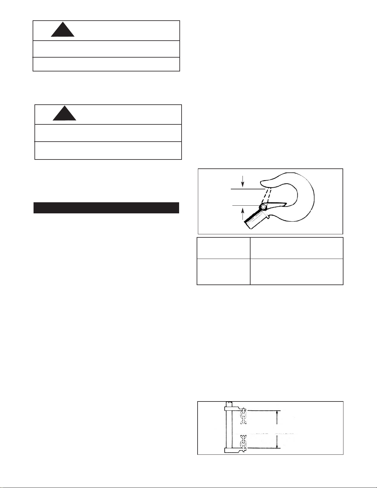
Hooks damaged from chemicals, deformations or cracks or that have more than a
10° twist from the plane of the unbent hook or excessive opening or seat wear must
be replaced.
Also, hooks that are opened and those that allow the latch to disengage the tip, must
be replaced.
Any hook that is twisted or has excessive throat opening indicates abuse or overloading of the unit. Other load-sustaining components of the hoist should be
inspected for damage.
The chart below should be used to determine when the hook must be replaced. To
measure throat opening, depress the latch against the hook body as shown below.
Hoist
Rated Load
Tons (Kg.)
1
⁄2(500)
1 (1000)
2 (2000)
3 (3000)
5 (5000)
10 (10000)
Replace Hook When
Opening Is Greater Than:
Inches mm
1.00 25.3
1.20 30.5
1.43 36.8
1.65 41.8
2.10 53.2
2.58 65.5
MEASURE
OPENING
HOOK THROAT OPENING
Also, check to make sure that the latch is not damaged or bent and that it operates
properly with sufficient spring pressure to keep the latch tightly against the tip of the
hook and allow the latch to spring back to the tip when released. If the latch does
not operate properly, it should be replaced.
LOAD CHAIN
Cleaning and Inspection
First clean the load chain with a non-acid or non-caustic type solvent then slack the
chain and make a link-by-link inspection for nicks, gouges, twisted links and excessive wear or stretching. Worn chain should be gaged throughout its entire length
and replaced if beyond serviceable limits.
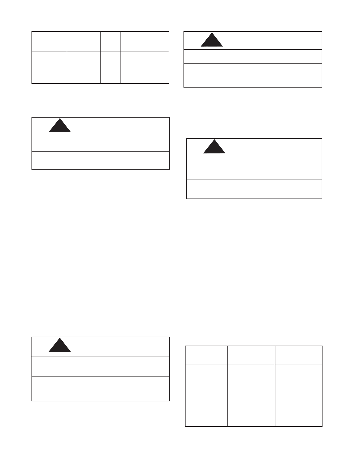
To determine if load chain should be continued in service, check gage lengths as
indicated in figure below. Chain worn beyond length indicated, nicked, gouged or
twisted should be replaced before returning hoist to service. Chain should be clean,
free of twists and pulled taut before measuring. In cases where the wear is localized
and not beyond serviceable limits, it is sometimes possible to reverse the load chain,
end for end, and allow a new section to take the wear. Proper installation of the load
chain is covered in section on Reeving Load Chain (page 7).
13. Never operate the hoist when flammable materials or vapors are present.
Sharp contact between metal parts can produce sparks that can cause a fire
or explosion.
14.STAY ALERT! Watch what you are doing and use common sense. Do not use
the hoist when you are tired, distracted or under the influence of drugs,
alcohol or medication causing diminished control.
11. Do not use this or any other overhead materials handling equipment for lifting
persons.
12. Do not allow the load to bear against the hook latch. The latch is to help
maintain the hook in position while the chain is slack before taking up slack
chain.
NUMBER OF
LINKS IN GAGE
GAGE
LENGTH
WARNING
Power operation may result in structural damage or premature wear that may
cause a part to break and allow the load to fall.
TO AVOID INJURY:
Operate Series 622 Hoists using hand power only.
h. Hooks — dye penetrant, magnetic particle or other suitable crack-detecting
inspections should be performed at least once a year, if external conditions
indicate there has been unusual usage.
Any deficiencies noted are to be corrected before the hoist is returned to service.
Also, the external conditions may show the need for more detailed inspection which,
in turn, may require the use of nondestructive-type testing.
Any parts that are deemed unserviceable are to be replaced with new parts before
the unit is returned to service. It is very important that the unserviceable parts be
destroyed to prevent possible future use as a repair item and properly disposed of.
!
!
Page 7
6
Hoist
Rated Load
Tons (Kg.)
1
⁄
2
(500)
1 (1000)
2-10
(2000-10000)
Hand Chain
Chain Stock
Diameter
In. (mm)
0.197 (5)
0.236 (6)
0.394 (10)
0.194 (4.9)
No. of
Links
to
Gage
11
11
11
15
Max. Length
Allowable for
Used Chain
In. (mm)
7.031 (178.6)
8.531 (216.7)
14.125 (358.7)
14.812(376.2)
IMPORTANT: Do not use replaced chain for other purposes such as lifting or pulling. Load chain may
break suddenly without visual deformation. For this
reason, cut replaced chain into short lengths to prevent use after disposal.
Note that worn chain can be an indication of worn hoist components. For this reason, the hoist’s chain guide roller and liftwheel should be examined for wear and
replaced as necessary when replacing worn chain.
Also, load chains are specially heat treated and hardened and should never be
repaired.
WARNING
Using other than CM-supplied load chain may cause the chain to jam in the
hoist and/or allow the chain to break and the load to drop.
TO AVOID INJURY:
Due to the size requirements and physical properties, use only CM Hoistaloy®
load chain in the Series 622 Hand Hois
t.
Before returning chain to service or after replacing a load chain, lubricate liberally
with Lubriplate Bar and Chain Oil 10-R (Fiske Bros. Refining Co.) or equal lubricant.
Remove excess lubricant from the chain by wiping with a cloth.
HAND CHAIN
Hand chain should be cleaned, inspected and gaged in the same manner as load
chain.
As received from the factory, the hand chain contains an unwelded link. This link can
be placed in a vise and twisted open to facilitate changing chain length. Please note
that opening and closing of the connecting link more than twice is not recommended.
Also, connecting links must not be made by cutting the weld side of a standard hand
chain link.
Hand chain should be assembled to handwheel free from twists with weld on vertical
link facing inwards towards handwheel and weld on horizontal link facing towards the
handwheel side plate.
Care must be taken to assure that there is no twist in the hand chain loop.
LUBRICATION
WARNING
The Lubricants used in and recommended for the Series 622 Hand Hoist may
contain hazardous materials that mandate specified handling and diposal procedures.
AVOID CONTACT AND CONTAMINATION:
Handle and dispose of lubricants only as directed in applicable material safety
data sheets and in accordance with applicable local, state and federal regulations.
Lubricate load chain with a light coat of Lubriplate Bar and Chain Oil 10-R (Fiske
Bros. Refining Co.) or equal lubricant. Be sure the lubricant reaches the bearing surfaces between the links. Remove excess oil from the chain.
WARNING
Used motor oils contain unknown carcinogenic materials.
TO AVOID HEALTH PROBLEMS:
Never use used motor oils as a chain lubricant. Only use Lubriplate
Bar and Chain Oil 10-R as a lubricant for the load chain.
The hoist normally requires no additional lubrication, except for periodically
lubricating the load chain as indicated above or when the unit is disassembled for periodic inspections, cleaning or repairs.
The brake is designed to operate dry. Do not use any
grease or lubricant on the braking surfaces. When
lubricating parts adjacent to the brake, do not use an
excessive amount of lubricant which could seep onto
the brake surfaces.
WARNING
Using any grease or lubricant on the braking surfaces will cause brake slippage and loss of load control which may result in injury and/or property damage.
TO AVOID INJURY:
Do not use any grease or lubricant on braking surfaces. The brake is designed
to operate dry.
When the hoist is disassembled for periodic inspections, check the pawl for
free movement and apply a light coat of WD-40 (WD-40 Co.) lubricant to the
pawl stud.
When the hoist is disassembled for cleaning or repairs, the following locations should be lubricated using approximately 1 oz. (29.5mL) per hoist of
Molykote BR-2-S (Dow Corning Corp.) grease or equivalent—threads of
handwheel; gears; liftwheel rollers; gear bearing rollers; journals of chain
guide and dead end pin; sheave wheel rollers (3, 5 and 10 ton); hook ball
bearings (3 and 5 ton); hook collar journals (3 and 5 ton); dead end stud (3,
5 and 10 ton); bearing surface of hook knob (10 ton); hook block pin (10
ton); and hanger pin (10 ton).
NOTE: To assure extra long life and top performance,
be sure to lubricate the various parts of the hoist using
the lubricants specified above. If desired, these lubricants may be purchased from CM. Refer to pages 8
and 10 for information on ordering the lubricants.
DISASSEMBLY
Two points of caution to be observed in disassembly are:
1. Loose rollers and bearing balls are used in various locations in the
units. Care must be taken so as to not lose or misplace these since
they may drop from the unit as the various parts are disassembled.
The number of rollers or bearing balls used are:
Hoist Rated
Load
Tons (Kg.)
1 (1000)
2-10
(2000-10000)
1/2 (500)
1 (1000)
2-10
(2000-10000)
3 -5
(3000-5000)
3 (3000)
5 (5000)
10 (10000)
Location
Intermed. Gear
Intermed. Gear
Liftwheel
Liftwheel
Liftwheel
Sheave Wheel
Hook
Hook
Sheave Wheel
Rollers
Required
12 Each End
11 Each End
33 Each End
30 Each End
35 Each End
29
*15
*16
36
*Bearing Balls
!
!
!
!
Page 8
7
2. The latch is secured to the hook (upper and lower) by a rivet. To
remove the latch, it is necessary to remove the head of the rivet by
grinding or drilling. For replacement of the latch, refer to paragraph 4
of the Assembly Instructions.
ASSEMBLY
Consideration must be given to the following when assembling the hoist:
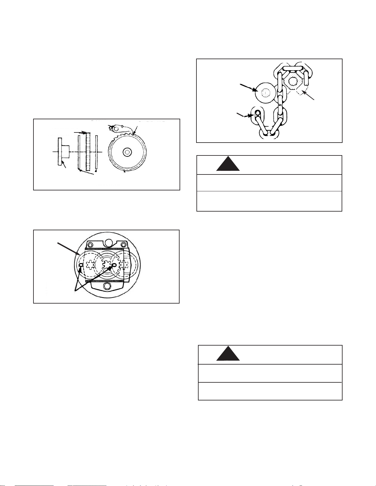
1. Assemble the brake components as shown below. The ratchet teeth
must face as shown and engage the pawl. Do not lubricate the brake
surfaces. The brake operates dry. Assemble handwheel to pinion
shaft and turn handwheel to seat brake components. Assemble the
pinion shaft nut to the shaft until the nut bottoms. Then back nut off at
least one but not more than two flats. Insert cotter pin and bend ends
to secure same.
* 1/2 ton hoist has two pawls 180° apart.
* PAWL
RATCHET
RATCHET
FRICTION
HUB
FRICTION
WASHER
INTERMEDIATE
GEAR
TIMING
MARKS
2. The intermediate gears (622-8) have timing marks (letter “O” stamped
on one tooth). The gears must be assembled with these marks orientated as shown below.
3. For proper operation, the correct number of rollers must be installed at the
rotating points of the liftwheel, intermediate gears, hook block sheave (3, 5 and
10 ton) and hoist hanger sheave (10 ton). Also, on the 3 and 5 ton units, the
correct number of bearing balls must be installed in the hook collar to retain the
hook and insure proper loading. Refer to Disassembly Instructions above for
the number of rollers at these locations. Applying grease, Molykote BR - 2 - S
(Dow Corning Corp.) or equal EP grease, to the rollers or bearing balls will
help hold them in position during assembly.
4. When assembling the latch to the hook, the end of the rivet must be peened
over. When peening over the rivet, only apply enough force to form the head
and retain the rivet. Excessive force will deform the latch and make the latch
inoperable.
REEVING LOAD CHAIN
A. 1/2, 1, 2, 3, 5 and 10 Ton Hoists
Attach approximately 20”(508mm) of soft wire to the loose end of the chain. Pass
the wire over the top of the liftwheel (622-13) and down between the liftwheel and the
chain guide (622-16). Position the chain so that the first, as well as the third, link
stands on edge with the weld away from the liftwheel and the second link lays flat on
the liftwheel. After the chain has been started, pull hand chain in the hoisting direction until about 2 feet (0.6M) of chain has passed over the liftwheel. The wire should
now be removed from the chain. Remove the cotter pin from the loose end pin (622-
15) and slide the loose end pin to the side into the gear housing, leaving approximately 1/2”(12.7mm) of the pin protruding from the geared side plate (622-5). Loop
the chain, making sure there are no twists, up to the loose end pin and slide the pin
B. 3 and 5 Ton Hoists
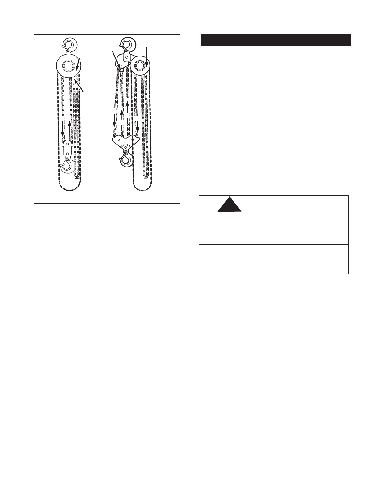
The load chain must have an odd number of links. After attaching the chain to the
loose end pin per above, operate in the hoisting direction until the load end of the
chain is approximately 5 feet (1.5M ) long. Run chain thru the hook block (first link
around the sheave must stand on edge) and up to the dead end block (622-26).
Secure chain to dead end block using the stud, nut and cotter pin. Refer to illustration below.
through the last link of the chain. Slide the loose end pin into hole in the handwheel side
plate (622-4). until the cotter pin hole is visible. Secure the loose end pin by reinstalling
the cotter pin and spreading the legs of the cotter pin.
LIFTWHEEL
622-13
CHAIN GUIDE
622-16
LOOSE END
PIN 622-15
WARNING
Failure to properly install the load chain between chain guide and liftwheel may
cause the chain to lift out of the liftwheel pockets and allow the load to drop.
TO AVOID INJURY:
Feed load chain between liftwheel and chain guide, as shown above, before
attaching it to the loose end pin.
10 Ton Hoist
The load chain must have an odd number of links. After attaching the chain to the
loose end pin per above, operate in the hoisting direction until the load end of the
chain is approximately 20 feet (6M) long. Run the chain thru the hook block (first
link around the sheave must stand on edge) around the first hook block sheave, up
around the hanger sheave, down around the second hook block sheave and up to
the hoist hanger. Secure the chain to the hoist hanger using the dead end stud, nut
and cotter pin (622-38). Refer to Illustration below.
WARNING
TO AVOID INJURY:
Check each stage of reeving the chain to be sure it has no twists.
On the 3, 5 and 10 ton units, twisted load chain will cause the chain to jam in
the liftwheel or sheave wheels and this may break the chain and allow the load
to drop.
!
!
Page 9
8
REEVING
3 and 5-Ton Hoist
DEAD
END
BLOCK
1
1
3
4
2
2
DEAD
END
BLOCK
LOOSE
END
PIN
LOOSE
END
PIN
REEVING
10-Ton Hoist
EXTERIOR FINISH
The exterior surfaces of the hoists have a durable, scratch resistant finish. Normally,
the exterior surfaces can be cleaned by wiping with a cloth. However, if the finish is
damaged, compatible touch-up paint can be purchased from CM. Order one case
(12-12 oz.-354mL aerosol cans) of orange touch-up paint Part Number 84190.
Touch-up paint is only available in case quantities. See below for ordering information.
RECOMMENDED SPARE PARTS
To insure continued operation, it is recommended that two friction washers for each
Series 622 Hand Hoist in service, Key No. 622-39, be kept on hand at all times to
replace friction washers that are worn, contaminated or glazed. See below for
ordering information.
PREVENTIVE MAINTENANCE
In addition to the periodic inspection procedure, a preventive maintenance program
should be established to prolong the useful life of the hoist and maintain its dependability and continued safe use. The program should include the periodic inspections with particular attention being paid to the lubrication of various components
using the recommended lubricants.
TESTING
Before using, all altered, repaired or used hoists that have not been operated for the
previous 12 months should be tested by the user for proper operation. First, test the
unit without a load and then with a light load of 50 pounds (23Kg.) times the number
of load supporting chains to be sure that the hoist operates properly and that the
brake holds the load when the hand chain is released. Next test with a load of
125% of rated capacity. In addition, hoists in which load sustaining parts have been
replaced should be tested with 125% of rated capacity by or under the direction of
an appointed person and written report prepared for record purposes.
NOTE: For additional information on inspection and
testing, refer to Code B30.16 “Overhead Hoists”
obtainable from ASME Order Department, 22 Law
The following information must accompany all correspondence or repair parts
orders.
1. Hoist Capacity
2. Serial Number -- stamped on the capacity label.
For parts orders also specify:
1. Quantity desired
2. Key Number of Part
3. Part Name
4. Part Number
When ordering replacement parts, consideration should be given to the need to
replace other items, (springs, fasteners, etc.) and items that may be damaged or
lost during disassembly or just unfit for future use because of deterioration from age
or service.
Parts should be ordered from CM’s Master Parts Depots conveniently located
throughout the United States and Canada. Refer to the inside of the front cover of
this manual to locate the Master Parts Depot nearest you.
ORDERING INFORMATION
WARNING
Using “commercial” or other manufacturer’s parts to repair the CM Series 622
Hoist may cause load loss.
TO AVOID INJURY:
Use only CM supplied replacement parts. Parts may look alike but CM parts
are made of specific materials or processed to achieve specific properties.
!
Page 10
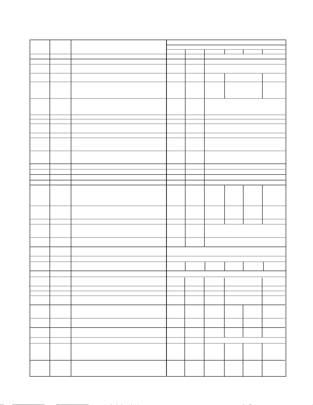
9
SERIES 622 HAND HOIST
PARTS LIST
Handwheel Cover with Studs
622-1
622-2
622-3
622-4
622-5
622-6
622-7
622-8
622-9
622-10
622-11
622-12
622-13
622-14
622-15
622-16
622-17
622-18
622-19
622-20
622-21
622-22
622-23
622-24
622-25
1
1
1
1
1
1
1
1
1
1
1
1
1
1
1
1
1
1
2
1
-
-
1
1
1
Handwheel
Brake Set (2 Friction Washers, Ratchet
and Hub)
Handwheel Side Plate (includes
Bearing Race, Pawl and Pawl Spring)
Geared Side Plate (includes Bearing
Race, 2 Bushings and 3 Studs. 2
Roller Shield Washers also provided
for 2, 3, 5 and 10 Ton)
Main Hardware Set (2 Gear Cover
Nuts, 3 Handwheel Cover Nuts and
Lockwashers, 6 Side Plate Nuts and
Lockwashers)
Gear Cover with Studs
Gear Set
Gear Set Roller Kit (48 Rollers for 1Ton, 44 Rollers for 2, 3, 5 and 10 Ton)
Pinion Shaft
Pinion and Liftwheel Hardware Kit
(Pinion Shaft Nut, Cotter Pin and
Liftwheel Snap Ring)
Liftwheel Roller Kit (66 Rollers for 1/2
Ton, 60 Rollers for 1 Ton, 70 Rollers for
2, 3, 5 and 10 Ton)
Liftwheel (includes 2 Bearing Races)
Stripper
Chain Guide Roller
Upper Hook Assembly (includes Hook
with Latch, Hook Block, Clevis Pin and
Cotter Pin for 1/2, 1 and 2 Ton; Hook
with Latch, Hook Block, Bearing Balls
and Set Screw for 3 and 5 Ton)
Lower Hook Assembly (includes
Hook with Latch, Hook Block, Screw,
Nut and Cotter Pin)
Latch Kit (Latch, Spring and Rivet)
Gear Cage with Bushings (includes 2
Roller Shield Washers for 2, 3, 5 and
10 Ton)
Load Chain (Specify Lift or Length
Required.)
Hand Chain (Specify Lift or Length
Required.)
Warning Tube
Label Set (Capacity and Warning
Labels and 8 Drive Screws)
Hand Chain Connecting Link
Loose End Pin (includes 2 Cotter Pins)
KEY
NO.
NO.
REQ’D
PART NUMBER
10 (10000)3 (3000) 5 (5000)
Rated Load—Tons (Kg.)
PART NUMBER
22910 22791 22812
22911 22792 22813
22912 22793 22814
22915 22797 22818
22917 22800 22821
22918 22801 22822
22781 22802 22823
22919 22803 22824
22920 22804 22825
22921 22805 22927
22922 22806 22827
22923 22807 22830 22836 22847 —
22787 22808 22831 — — —
22928 22929 22930 22933 22934 22937
22924 22810 22829
85834 85959 85960
946735
22603 22604 22608 22609 22610 22611
661019
85832
22913 22794 22925 22931 22935
22914 22795 22926 22932 22936
22775 22796 22817
22916 22798 22819
— 22799 22820
1/2 (500) 1 (1000) 2 (2000)
622-26
622-28
1
1
Dead End Kit (includes 2 Anchor
Plates, Stud, Nut and Cotter Pin)
— — — 22841 —Sheave Shaft
622-29
1
— — — 22842 —Sheave Wheel
622-30
1
— — — 22843 —
Sheave Shaft Hardware Kit (29
Rollers and 2 Snap Rings)
622-31
1
— — — 22844 22850 —
Lower Hook Assembly (includes Hook
Block, Hook with Latch, Bearing Balls,
Set Screw and 2 Snap Rings)
622-36
1
— — — — — 22864
Hoist Hanger Kit (Hanger Pin and 2
Cotter Pins)
622-38
1 — — — — — 22866
Dead End Kit (Stud, Nut and Cotter
Pin)
622-39
2
22867 22868 22869
Friction Washer
622-40 1
— — — — — 22938
Hoist Hanger Assembly (includes
Hanger, Sheave Wheel, Hook with
Latch, Hook Block, Dead End
Anchor, Shafts and Snap Rings)
622-41
1
— — — — — 22939
Lower Hook Block Assembly
(includes Hook Block, Hook with
Latch, Sheave Wheels, Shafts and
Snap Rings)
— — — 22839 —
——— —
Page 11
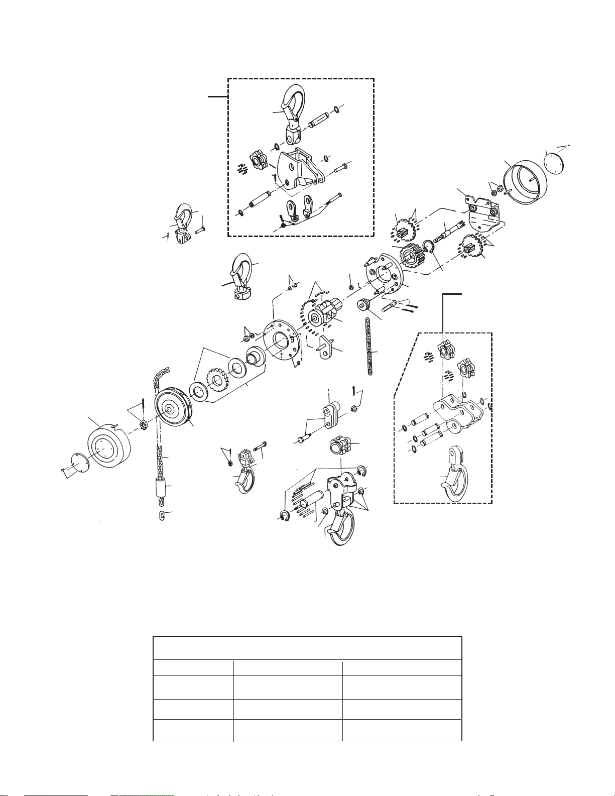
10
PART NUMBERS FOR PACKAGED LUBRICANTS
Used in the Series 622 Hand Hoists
(Refer to page 6 for Lubrication Instructions)
Lubricant
Usage
Gears, Rollers of
Liftwheel and
Gear Bearings
Pawl Stud
Load Chain
Type of
Lubricant
Grease (Molykote BR-2-S
or Equal)
Oil (WD-40 or Equal)
Oil (Lubriplate Bar and
Chain Oil 10-R or Equal)
Part Numbers and Packaged
Quantities of Lubricants
28606 - 1/2 lb.(.23Kg.) can
28618 - 1 lb.(.46Kg.) can
Obtain locally—not stocked
by CM
28608 - 1 pint (.5L) can
28619 - 1 gal.(3.8L) can
Series 622 Hand Hoist
Exploded View
NOTE: Metric Tools Required
for Fasteners.
622-40, 10 Ton Hoist Hanger
Assembly. Except for Latch
Kit, Hoist Hanger Kit and Dead
End Kit, individual parts are
not available for repairs.
627-41, 10 Ton Lower Hook
Block Assembly. Except for
Hook Latch, individual parts
are not available for repairs.
1/2, 1 and 2
Ton
1/2, 1 and 2
Ton
3 & 5 Ton Lower
Hook Block
3 & 5 Ton
Upper Hooks
622-19
622-19
622-17
622-17
622-17
622-24
622-1
622-11
622-22
622-23
622-25
622-19
622-18
622-18
622-2
622-3
622-39
622-6
622-6
622-12
622-13
622-6
622-16
622-15
622-5
622-11
622-8
622-8
622-19
622-36
622-38
622-36
622-9
622-10
622-20
622-6
622-7
622-24
622-9
622-8
622-16
622-4
622-26
622-26
622-29
622-30
622-28
622-31
622-19
622-31
622-19
622-14
622-19
 Loading...