


Columbus McKinnon Entertainment Division
PROSTAR
Operating, Maintenance &
Parts Manual
Follow all instructions and warnings for inspecting, maintaining and operating
this hoist.
The use of any hoist presents some risk of personal injury or property damage. That risk is greatly increased if proper instructions and warnings are not followed. Before using this hoist, each operator should become thoroughly familiar with all warnings, instructions, and recommendations in this manual. Retain this manual for future reference and use.
Forward this manual to the hoist operator. Failure to operate the equipment as directed in the manual may cause injury.
Before using the hoist, fill in the information below:
Capacity
Serial No.
Voltage
Purchase Date
Capacities
250 lb (113 Kg) |
300 lb (136 Kg) |
500 lb (226 Kg) |
550 lb (250 Kg) |
600 lb (272 Kg) |
1,000 lb (453 Kg) |
1,100 lb (500 Kg)
20875
Revision P620-AB
SAFETY PRECAUTIONS
Each Prostar Electric Hoist is built in accordance with the specifications contained herein and at the time of manufacture complied with our interpretation of applicable sections of the National Electrical Code (ANSI/NFPA 70). Installers are required to provide current overload protection and grounding in keeping with the code. Check each installation for compliance with the applicable sections of the code as well as the National, State and Local Codes that may apply to the installation. In addition, safety code requirements associated with the operation of a hoist in the inverted (theatrical) position (chain port up), as with any mechanical equipment, vary depending upon locality. Therefore, before installing the hoist, the user should consult his insurance company and/or local authority to see if a deviation is required to permit the use of the hoist in this particular application.
The safety laws for elevators, lifting of people and for dumbwaiters specify construction details that are not incorporated into the hoists. For such applications, refer to the requirements of applicable state and local codes, and the American National Safety Code for elevators, dumbwaiters, escalators and moving walks (ASME A17.1). We cannot be responsible for applications other than those for which the equipment is intended.
THIS SYMBOLPOINTSOUTIMPORTANTSAFETYINSTRUCTIONSWHICHIFNOT
FOLLOWEDCOULDENDANGER THEPERSONALSAFETYAND/OR PROPERTYOF
YOURSELFAND OTHERS. READANDFOLLOW ALLINSTRUCTIONSINTHIS
MANUALANDANYPROVIDED WITHTHE EQUIPMENTBEFORE ATTEMPTINGTO
OPERATEYOURPROSTARHOIST.
 WAR NING
Improper operation of a hoist can create a potentiallyhazardous situation which, if not avoided, could result in death or serious injury. To avoid such a potentiallyhazardous situation,the operator shall:
1. |
NOT operate a damaged, malfunctioning or unusually |
|
performing hoist. |
2. |
NOT operate the hoist until you have thoroughly read |
|
and understood this Operating, Maintenance and Parts |
|
Manual. |
3. |
NOT operate a hoist which has been modified. |
4. |
NOT lift more than rated load for the hoist. |
5. |
NOT use hoist with twisted, kinked, damaged, or worn |
|
load chain. |
6. |
NOT use the hoist to lift, support, or transport people. |
7. |
NOT lift loads over people. |
8. |
NOT operate a hoist unless all persons are and remain |
|
clear of the supported load. |
9. |
NOT operate unless load is centered under hoist. |
10. |
NOT attempt to lengthen the load chain or repair |
|
damaged load chain. |
11. |
Protect the hoist’s load chain from weld splatter or other |
|
damaging contaminants. |
12. |
NOT operate hoist when it is restricted from forming a |
|
straight line from hook to hook in the direction of loading. |
13. |
NOT use load chain as a sling, or wrap load chain |
|
around load. |
14. |
NOT apply load to the tip of the hook or to the hook latch. |
15. |
NOT apply the load unless load chain is properly |
|
seated in the chain wheel(s) or sprocket(s). |
16. |
NOT apply load if bearing prevents equal loading on all |
|
load supporting chains. |
17. |
NOT operate beyond the limits of the load chain travel. |
18. |
NOT leave load supported by the hoist unattended |
|
unless specific precautions have been taken. |
19. |
NOT allow the load chain or hook to be used as an |
|
electrical or welding ground. |
20. |
NOT allow the load chain or hook to be touched by a |
|
live welding electrode. |
21. |
NOT remove or obscure the warnings on the hoist. |
22. |
NOT operate a hoist on which the safety placards or |
|
decals are missing or illegible. |
23. |
NOT operate a hoist unless it has been securely |
|
attached to a suitable support. |
24. |
NOT operate a hoist unless load slings or other |
|
approved single attachments are properly sized and |
|
seated in the hook saddle. |
25. |
Take up slack carefully - make sure load is balanced |
|
and load holding action is secure before continuing. |
26. |
Shut down a hoist that malfunctions or performs |
|
unusually and report such malfunction. |
1 |
|
27.Make sure hoist limit devices function properly.
28.Warn personnel of an approaching load.
 CAUTION
Improper operation of a hoist can create a potentiallyhazardous situation which, if not avoided, could result in death or serious injury. To avoid such a potentiallyhazardous situation,the operator shall:
1.Maintain a firm footing or be otherwise secured when operating the hoist.
2.Check brake function by tensioning the hoist prior to each lift operation.
3.Use hook latches. Latches are to retain slings, chains, etc. under slack conditions only.
4.Make sure the hook latches are closed and not supporting any parts of the load.
5.Make sure the load is free to move and will clear all obstructions.
6.Avoid swinging the load or hook.
7.Make sure hook travel is in the same direction as shown on the controls.
8.Inspect the hoist regularly, replace damaged or worn parts, and keep appropriate records of maintenance.
9.Use factory parts when repairing the unit.
10.Lubricate load chain per instructions in this manual.
11.NOT use the hoist load limiting or warning device to measure load.
12.NOT use limit devices as routine operating stops unless allowed by manufacturer. They are emergency devices only.
13.NOT allow your attention to be diverted from operating the hoist.
14.NOT allow the hoist to be subjected to sharp contact with other hoists, structures, or objects through misuse.
15.NOT adjust or repair the hoist unless qualified to perform such adjustments or repairs.
TABLE OF CONTENTS
Safety Precautions ............................................................. |
1 |
Specifications ..................................................................... |
2 |
Installation .......................................................................... |
3 |
Operating Instructions ........................................................ |
5 |
Maintenance....................................................................... |
6 |
Trouble Shooting .............................................................. |
10 |
Electrical Data .................................................................. |
11 |
Disassembly-Assembly .................................................... |
13 |
Repair Parts ..................................................................... |
14 |
Exploded View.................................................................. |
16 |
Replacement Parts List.................................................... |
18 |
Warranty ............................................................ |
Back Cover |
|
|
|
|
|
|
|
|
|
|
|
Figure 1A |
|
Figure 1B |
|
|
|
|
|
|
SPECIFICATIONS
The Prostar Electric Chain Hoist is a highly versatile materials handling device that can be used to lift loads that are within its rated load capacity. It is available in six load ratings.
Standard features of the Prostar Electric Chain Hoist include:
•Alloy steel, oblique lay liftwheel that provides constant chain speed and reduces chain wear.
•Hoistaloy® load chain for long and dependable service.
•Grease lubricated, hardened spur gears provide smooth and quiet operation.
•Thermally protected, hoist duty motor.
•Forged steel upper and lower hooks with latch.
•Protector™ that prevents lifting dangerous overloads.
•D.C. disc type motor brake plus regenerative braking.
•Standard Less Chain Unit. Longer lifts can be supplied on a per order basis.
•3 foot (.9 M) power cord with provisions for grounding is standard on 115-50/60, 220-1-50 and three phase units.
•3 foot (.9M) is standard for all control cords. Longer cords can be provided on a per order basis.
•Lightweight die cast aluminum frames and covers.
•Ball or needle bearings at all rotating points.
•Compact, yet rugged, design provides minimum headroom and long, trouble-free service.
•6 fpm (1.8 m/min) lift speed available on 1000 lbs (453 kg) units.
•8 fpm (2.4 m/min) lift speed available on 500-600-1000 lbs (226, 272 and 453 kg) units.
•12 fpm (3.6 m/min) lift speeds available on 500-600- 1000 lbs (226, 272 and 453 kg) units.
•16 fpm (4.9 m/min) lift speeds available on 250-300- 500 lbs (113, 136 and 226 kg) units.
•20 fpm (6.1 m/min) lift speeds available on 500-600 lbs (226 and 272 kg) units.
•24 fpm (7.3 m/min) lift speeds available on 250-300- 500 lbs (113, 136 and 226 kg) units.
•40 fpm (12.2 m/min) lift speeds available on 250-300 lbs (113 and 136 kg) units.
•220-1-50, 380 to 460-3-50/60, 220 to 240-3-50/60 and 575-3-60 units available. Lift speeds are based on 60 hertz power supply. For 50 hertz power supply lift speeds will be 5/6 of those indicated.
•13.3fpm (4.0m/min) lift speed available
on 550lbs (250Kg) units.
•UL and cUL listed.
•Lifetime Warranty.
REPAIR/REPLACEMENT POLICY
All Prostar Electric Chain Hoists are inspected and performance tested prior to shipment. If any properly maintained hoist develops a performance problem, due to a material or workmanship defect, as verified by the factory, repair or replacement of the unit will be made to the original purchaser without charge. This repair/replacement policy applies only to Prostar Hoists installed, maintained and operated as outlined in this manual, and specifically excludes hoists subject to normal wear, abuse, improper installation, improper or inadequate maintenance, hostile environmental effects and unauthorized repairs/modifications.
We reserve the right to change materials or design if, in our opinion, such changes will improve our product. Abuse, repair by an unauthorized person, or use of non-factory replacement parts voids the guarantee and could lead to dangerous operation. All Prostar Electric Chain Hoists are backed with a lifetime warranty. Refer to the back cover for details and limitations.
Alterationsor modificationof hoist and use of non-factoryrepair parts can lead to dangerous operation and injury.
TO AVOID INJURY:
•Do not alter or modify equipment.
•Do use only factory replacementparts.
ACCESSORIES
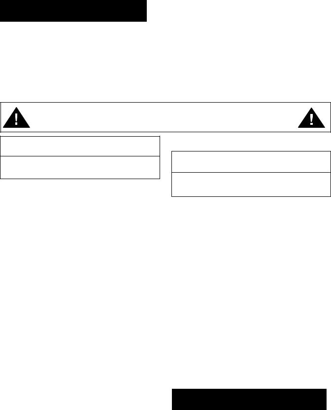
Chain Container
This accessory item (Figure 1A) is used to hold the slack chain and it is supplied with mounting hardware and instructions. Chain containers are recommended for those applications where slack chain will interfere with the load or drag on the floor as may more often be the case with the Double-reeved units. Chain containers are shipped separately and can be furnished for units already in service.
Latchlok® Hooks
Latchlok Hooks (Figure 1B) are available to replace the standard lower latch type hooks. The unique design of the Latchlok Hook assures that it will stay locked until the operator releases it by depressing the release button. It will not open accidentally–even if the load chain goes slack. Once opened, it can be shut with one hand or the weight of the load when it is lifted. Latchlok Hooks can be supplied with the hoist or they can be provided in kit form for hoists already in service.
2

Figure 2A
BC Series Beam Clamps
The beam clamps are ideal as anchors for rigging applications (Figure 2A). The BC series clamps can be adjusted to fit a wide range of beam sizes. The lightweight and compact design makes the beam clamps ideal for repeated set-ups and tear-downs.
Entertainment Rigging Products
Refer to sales Bulletin No. EPD-10B for additional rigging products that can be used in the entertainment industry.
INSTALLATION
UNPACKING
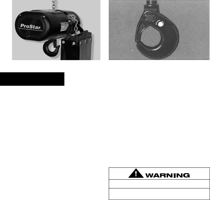
After opening the carton (Figure 2B) , carefully inspect the hoist frame, cords, hooks, chain and control station for damage that may have occurred during shipment. If there is damage, refer to the packing slip envelope.
Make sure that the power supply (Figure 3A) to which the hoist is to be connected is the same as that shown on the identification plate located on bottom of hoist.
Operating a unit with obvious external damage may cause load to drop and that may result in personal injury and/or property damage.
TO AVOID INJURY:
Carefully check unit for external damage prior to installation.
MOUNTING THE HOIST
Attach the hoist to the truss/structureto be lifted using the mounting hook (Figure 3B) . Be sure that the attachment point is held in the lowermost part of the hook arc and the latch is tightly against the hook tip. Also, the attachment point must have sufficient strength to withstand several times the load imposed. If in doubt, consult a registered engineer and local building codes.
An inadequateattachmentpoint may allow the hoist and load to fall and cause injury and/or property damage.
TO AVOID INJURY:
Make sure the attachmentpoint has sufficientstrength to hold several times the hoist and its rated load.
Claim Procedure
Figure 2B
POWER SUPPLY SYSTEM
(Refer to Figure 4A or 4B on page 5). To insure proper operation, to avoid damage to hoist and electrical system and to reduce the risk of electric shock or fire, the branch circuit supplying power to the hoist must:
1.Have ample capacity to prevent excessive voltage drop during starting and operation (refer to “Checking for Adequate Voltage at Hoist” on page 4). When determining the size of branch circuit components and conductors, special consideration should be given to the starting current-amps (approximately three times that shown on the hoist identification plate) and the length of the conductors. As a minimum, the system should be rated for 15 amps and it should have #16 AWG, or larger, wiring.
2.Be in accordance with the National Electrical Code (ANSI/NFPA-70) and applicable National, State and Local Codes.
3.Effectively ground the hoist in accordance with National Electrical Code and other applicable codes. Proper grounding provides a path of least resistance for electric current to reduce the risk of electric shock. The power cord of the hoist includes a green-yellow wire for grounding the hoist to the external power supply system. Be sure that the receptacle opening that receives the longest prong is properly grounded. If grounding is to be through the trolley trackwheels, each section of the runway must be grounded to the building ground system using metal to metal connections.
4.Include slow blow type fuses or inverse trip time circuit breakers to permit the hoist to start and accelerate load.
Failure to properly ground the hoist presents the danger of electric shock.
TO AVOID INJURY:
Permanentlyground the hoist as instructedin this manual.
5.Include a disconnecting means capable of being locked in the “open” position.
3
Same |
Name |
|
plate |
||
|
Power supply |
|
Making sure the hoist will operate on |
|
|
|
the power supply system |
|
|
|
|
|
|
|
|
|
Figure 3A |
|
|
|
NOTE: IN THIS MANUAL, NOMINAL VOLTAGES ARE |
||
USED WHEN REFERRING TO POWER SUPPLY |
||
SYSTEMS. HOWEVER, WITH NO MODIFICATION, THE |
||
PROSTAR HOIST WILL OPERATE ON A RANGE OF |
||
VOLTAGES AS INDICATED BELOW: |
|
|
|
|
|
NOMINAL |
VOLTAGE |
HERTZ |
VOLTAGE |
RANGE |
|
230 |
208-240 |
60 |
460 |
440-480 |
60 |
220 |
200-240 |
50 |
380 |
365-395 |
50 |
415 |
400-430 |
50 |
575 |
550-600 |
60 |
Three Phase Hoists
Since the motor in a three phase hoist can rotate in either direction, depending on the manner in which it is connected to the power supply, the direction of hook movement must be checked during the original installation and each time hoist is moved to a new location as follows:
1.Move the manual disconnect switch handle to the “OFF” position.
2.Connect the BROWN, GREY AND BLACK wires of hoist power cord to load side of disconnect switch. Connect the GREEN-YELLOW wire of hoist power cord to power supply ground.
3.Move the manual disconnect switch handle to the “ON” position.
4. Depress the (up) control. If the hook moves in the up direction, the hoist is ready for operation. If the hook lowers, move the disconnect switch handle to the “OFF” position and interchange the BLACK and BROWN leads at the disconnect switch. Move the disconnect switch handle to the “ON” position and the hoist is now ready for operation.
Checking for Adequate Voltage at Hoist
The hoist must be supplied with adequate electrical power for proper operation and to reduce problems that may result from insufficient power (low voltage). These include:
•Noisy hoist operation due to brake and/or contactor chatter.
•Heating of the hoist motor and other internal components as well as heating of wires and connectors in the circuit feeding the hoist.
•Failure of the hoist to lift the load due to motor stalling.
•Blowing fuses or tripping circuit breakers.
•Dimming of lights or slowing of motors connected to the same circuit.
Load Hook
Chain
Stop
Loose
End of
Chain Control
Power Station
Cord
Mounting Hook
Figure 3B
For proper operation and to avoid these low voltage problems, voltage (measured at end of the power cord while
lifting rated load) should be as the following chart indicates. |
||
|
|
|
NOMINAL |
MINIMUM |
* MIN. VOLTAGE |
POWER |
OPERATING |
AT INSTANT |
SUPPLY |
VOLTAGE |
OF START |
115-1-50/60 |
108 |
103 |
220-1-50 |
198 |
182 |
208-3-60 |
187 |
172 |
220-3-50 |
198 |
182 |
230-3-60 |
207 |
190 |
380-3-50 |
365 |
336 |
415-3-50 |
399 |
367 |
460-3-60 |
414 |
380 |
575-3-60 |
518 |
506 |
*The drop in voltage upon energizing the hoist should not be below the value listed.
Low voltage can also be caused by using an undersize extension cord to supply power to the hoist. The following charts should be used to determine the size wires in the extension cord in order to minimize the voltage drop between the power source and the hoist.
115-1-50/60 units with contactor, 220-1-50 units and three |
||
phase units (hoists with black control station) |
||
|
||
MAXIMUM LENGTH OF EXTENSION CORD |
||
Wire Size |
Single |
Three |
|
Phase Hoist |
Phase Hoist |
#16 A.W.G. |
135 feet(40 M) |
245 feet(73 M) |
#14 A.W.G. |
220 feet(66 M) |
395 feet(120 M) |
#12 A.W.G. |
354 feet(107 M) |
630 feet(192 M) |
After the hoist is suspended from its support and you have made sure the power supply complies with the above, the hoist is ready for operation.
On the Double units, cut and discard the ties used to hold the two strands of chain together. With no load on the lower hook, depress the UP button in the control station and raise the lower hook until it is about 2 feet below the bottom of the hoist. Check both strands of chains for twists. Twists occur if the lower hook block has been capsized between the strands of chain during packing, shipment and/or handling. Reverse the capsize to remove twists.
4
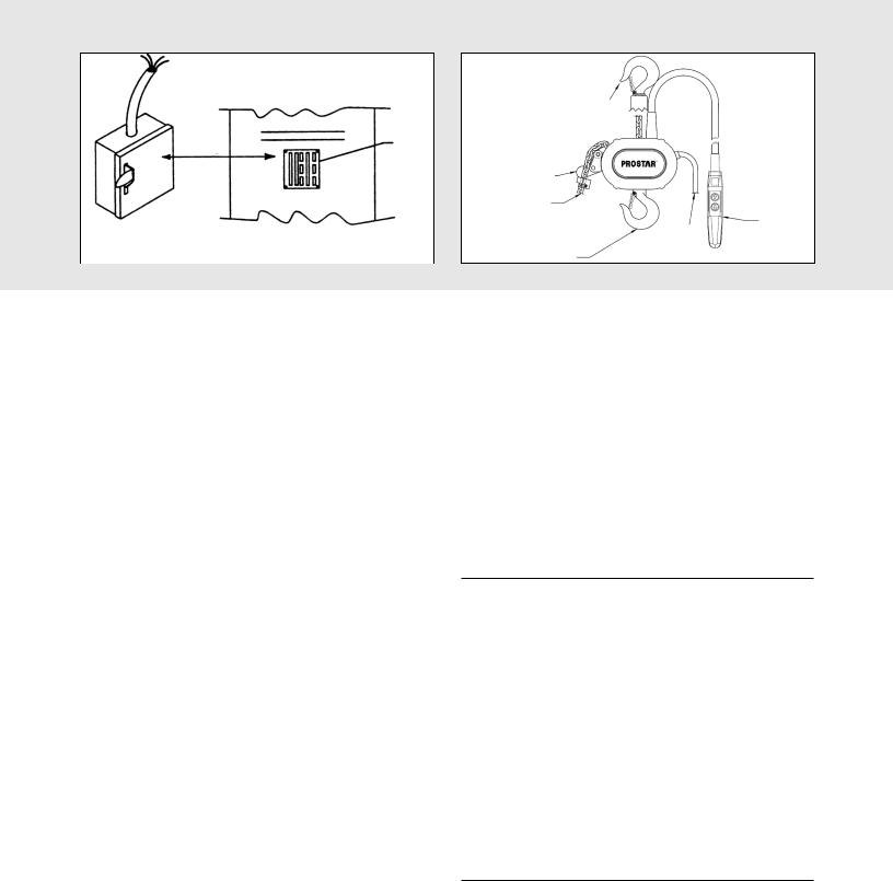
Single Phase Systems
* Manual |
*Slow Blow Fuses |
|
Disconnect |
or Inverse Time |
|
Switch |
Circuit Breakers |
|
Black |
|
Hoist Power |
|
|
Cord |
White |
|
|
Ground |
Blue |
Brown |
|
|
|
*Thermal Overload
Relay
Green-Yellow
*Receptacle Rated for 15 Amps Minimum (220-1-50 units do not include Power Cord Plug). Wire Blue and Brown Wires to Fuses or Circuit Breakers and Green-Yellow Wire to Ground.
Figure 4A
CHAIN CONTAINER
If the chain container is to be used, attach it to the hoist per the instructions provided.
OPERATING INSTRUCTION
The hoist is equipped with a Protector™ that is designed to allow the first gear to slip on an excessive overload. An overload is indicated when the hoist speed slows down, it raises the load in a jerky manner or it will not lift the load at all. Also, some clutching noise may be heard if the hoist is loaded beyond rated capacity. Should this occur, immediately release the UP button to stop the operation of the hoist. At this point, the load should be reduced to the rated capacity or the hoist should be replaced with one of the proper capacity. When the excessive load is removed, normal hoist operation is automatically restored.
CAUTION: The Protector™ is susceptible to overheating and wear when slipped for extended periods. Under no circumstance should the Protector be allowed to slip for more than a few seconds.
Due to the above, the hoist is not recommended for use in any application where there is a possibility of adding to an already suspended load to the point of overload. This includes dumbwaiter installations, containers that areloaded in mid-air, etc. Also, if the hoist is used at unusual extremes of ambient temperatures, above 150º F (65ºC). or below 15ºF (-9ºC)., changes in lubricant properties may permit the hoist to raise larger loads than under normal operating conditions and present possibility of damage or injury.
On units without contactor (hoists with orange control station) it is necessary to stop the hoist before changing direction. Therefore, when lowering a load, the push button in the control station must be released momentarily before the UP button is depressed to raise the load. If this is not done, the hoist will continue to operate in the down direction while the UP push button is depressed, and it will continue to lower the load until the control push button is released. As a result, the direction must not be reversed quickly (plug reversed).
There are no electrical switches to stop the operation of the hoist at the upper and lower limits of lift. As a result, it is necessary to release the push button in the control station to stop the hoist before the hook block or chain stop contacts the bottom of the hoist frame. If the hook block or chain stop contacts the hoist frame, the Protector will function to stop the hoisting or lowering operation and protect the hoist
Three Phase Systems
L1
Incoming Power |
L2 |
|
|
|
L3 |
|
Ground |
*Manual Disconnect Switch
*Must be per National Electrical Code and These Devices are to be Supplied by the User.
Black
Grey
Brown
Green-Yellow
Hoist Power Cord
*Slow Blow Fuses
or Inverse Time
Circuit Breakers
Figure 4B
components from damage. However, continued, prolonged or repeated slipping of the Protector will damage the Protector and cause overheating of the internal hoist components.
Allowing the hook block to run into the hoist when raising a load or allowing the chain stop to run into the hoist when lowering a load may break the chain and allow the load to drop.
TO AVOID INJURY:
Do not allow the hook block or the chain stop to contact the hoist frame.
Hoist operation is controlled by depressing the control station push buttons (Refer to Figure 5A, pg 6). Depressing the UP push button will move the load hook toward the hoist head; depressing the DOWN push button will move the load hook away from the hoist head.
The UP and DOWN buttons are momentary type and the hoist will operate in the selected direction as long as the button is held in the depressed position. Release the push button and the hoist will stop.
It is preferred that the load always be tied off with auxiliary chains or cables before access to the area beneath the load is permitted. As an alternative, the system may be designed such that malfunction or failure of one hoist’s load bearing components does not cause load loss and/or overloading of any other hoists in the system. Note that in such a system, hoist performance and function must be monitored visually or with the use of load cells. Check the supporting structure to which the load hook is to be attached. Make sure the attachment point as well as the structure have sufficient strength to withstand several times the load imposed. If in doubt, consult a registered engineer and local building codes.
5

Black Station for Hoists With Contactor
Control Station 
Depress to Move 
Load Hook Towards
Hoist Head
Depress to Move
Load Hook Away
From Hoist Head
Figure 5A
Attaching the load hook to an inadequate support may allow the hoist and load to fall and cause injury and/or property damage.
TO AVOID INJURY:
Make sure the structure and the load hook attachment point have sufficient strength to hold several times the hoist and rated load.
1.When preparing to lift a load, be sure that the attachments to the load hook are firmly seated in hook saddle. Avoid off center loading of any kind, especially loading on the point of the hook.
2.When lifting, raise the load only enough to clear the floor or support and check to be sure that the attachments to the hook and load are firmly seated. Continue lift only after you are assured the load is free of all obstructions.
3.Do not load the hoist beyond the rated capacity shown on the brake end cover. Overloading can cause immediate failure of some load-carrying part or create a defect causing subsequent failure at less than rated capacity. When in doubt, use the next larger capacity of hoist.
4.Do not use this or any other overhead materials handling equipment for lifting persons or allow people on unsecured load.
5.Stand clear of all loads and avoid moving a load over heads of other personnel. Warn personnel of your intention to move a load in their area. Do not leave unsecured load over people.
6.Do not leave the load suspended in the air unattended.
7.Permit only qualified personnel to operate unit.
8.Do not wrap the load chain around the supporting structure and hook onto itself as a choker chain. Doing this will result in:
a.The loss of the swivel effect of the load hook which could mean twisted chain and a jammed liftwheel.
b.The chain could be damaged at the load hook.
9.After positioning, secure load by using auxiliary cables and/or chains.
10.On the Double-reeved hoists, check for twists in the load chain. A twist can occur if the lower block has been capsized between the strands of chain. Reverse the capsize to remove twist.
11.Do not allow a load to bear against the hook latch. The latch is to help maintain the hook in position while the chain is slack before taking up the slack chain.
12.Take up a slack load chain carefully and start load easily to avoid shock and jerking of hoist chain. If there is any evidence of overloading, immediately lower the load and remove the excess load.
10°
MAX.
Replace
Hook When
Opening is
Greater
Than 1-1/8”
(28.5mm)
Twisted |
Normal |
Do Not Use |
Ok To Use |
Figure 5B
Allowing a load to bear against the hook latch and/or hook tip can result in loss of load.
TO AVOID INJURY:
Do not allow a load to bear against the hook latch and/or hook tip. Apply load to hook bowl or saddle only.
13.Do not allow the load to swing or twist while hoisting.
14.Never operate the hoist when flammable materials or vapors are present. Electrical devices produce arcs or sparks that can cause a fire or explosion.
15.STAY ALERT! Watch what you are doing and use common sense. Do not use the hoist when you are tired, distracted or under the influence of drugs, alcohol or medication causing diminished control.
|
|
|
|
|
|
|
|
|
|
|
|
|
TO AVOID INJURY: |
||
-DO NOT |
Lift more than rated load. |
||
-DO NOT |
Operate with twisted, kinked or damaged chain. |
||
-DO NOT |
Operate damaged or malfunctioning hoist. |
||
-DO NOT |
Lift people, loads over people, allow people on |
||
|
unsecured load or leave unsecured load over people. |
||
-DO NOT |
Operate hoist when load hook is not centered over |
||
|
hoist. |
||
-DO NOT |
Permit load hook block to contact hoist frame or chain |
||
|
container. |
||
-DO |
Replace damaged or malfunctioning hook latch. |
||
-DO |
Keep load chain well oiled. |
||
|
|
|
|
MAINTENANCE
INSPECTION
To maintain continuous and satisfactory operation, a regular inspection procedure must be initiated so that worn or damaged parts can be replaced before they become unsafe. The intervals of inspection must be determined by the individual application and are based upon the type of service to which the hoist will be subjected. The inspection of hoists is divided into two general classifications designated as “frequent” and “periodic”.
6
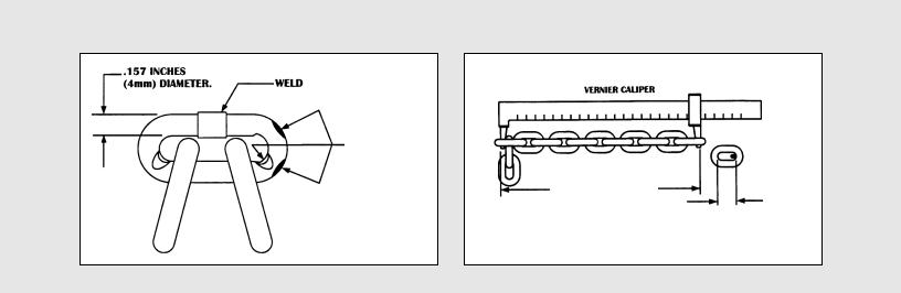
.157 Inches |
|
|
|
Vernier Caliper |
|
||||
(4 mm) Diameter |
|
Weld |
|
|
|
|
|
|
|
|
|
|
|
|
|
|
|
|
|
Wear in These
Areas
Measure 11 Pitches
One
Pitch
Figure 6A
Frequent Inspections
These inspections are usually visual examinations by the operator or other designated personnel. Frequent inspections are to be performed daily or monthly and shall include the following items:
a.Operate the hoist, with no load, and check for visual signs or abnormal noises which could indicate a potential problem - daily.
b.Brake for evidence of slippage - daily.
c.Chain for lubricant, wear, damaged links or foreign material - daily (see below).
d.Hooks for damage, cracks, twist, latch engagement and latch operation - daily (see below).
Any deficiencies must be corrected before the hoist is returned to service.
Periodic Inspections
There are visual inspections by an appointed person who records apparent external conditions to provide a basis for continuing evaluation. Periodic inspections are to be performed semi-annually and they should include the following:
a.All items listed under frequent inspections.
b.External evidence of loose screws.
c.External evidence of worn, corroded, cracked or distorted hook block, gears, bearings, chain stop and hook retainer.
d.External evidence of damage or excessive wear of the liftwheel or sheave (double-reeved unit). Widening and deepening of pockets may cause chain to lift-up in the pockets and cause binding between liftwheel and chain guide or between lower sheave and hook block. Check chain guide for wear or burring where the chain enters the hoist. Severely worn or damaged parts should be replaced.
e.External evidence of excessive wear of brake parts - see page 9.
f.Check the control station push buttons to make sure they operate freely and spring back when released.
g.Check power cord, control cord and control station for damaged insulation.
h.Check for pitting and any deterioration of contactor contacts (hoists with black control station).
i.Check the chain pin or dead end pin and chain stop for wear and cracks.
j.Check for lubricant leaks at gasket between main frame and gear housing. Tighten gear housing screws to stop leak. If leak persists, replace gasket.
k.Inspect splines on first pinion shaft and motor coupling for
7 |
signs of wear or deterioration. Replace splined parts if |
|
worn or damaged. |
||
|
Figure 6B
NOTE: To perform some of the periodic inspections, it is necessary to partially disassemble the hoist. Refer to Disassembly - Assembly starting on page 13.
Any deficiencies noted must be corrected before the hoist is returned to service. Also, the external conditions mayshow the need for more detailed inspection which, in turn, may require the use of nondestructive-type testing.
Any parts that are deemed unserviceable are to be replaced with new parts before the unit is returned to service. It is very important that the unserviceableparts be destroyed to prevent possible future use as a repair item and properly disposed of.
Hook Inspection
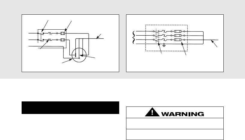
Hooks damaged from chemicals, deformations or cracks or that have more than a 10° twist from the plane of the unbent hook or excessive opening must be replaced.
Any hook that is twisted or has excessive throat opening indicates abuse or overloading of the unit. Other loadsustaining components of the hoist should be inspected for damage.
On latch type hooks, check to make sure thatthe latch is not damaged or bent and that it operates properly with sufficient spring pressure to keep the latch tightly against the tip of the hook and allow the latch to spring back to the tip when released. If the latch does not operate properly. It should be replaced. See Figure 5B, Pg. 6 to determine when the hook must be replaced.
LOAD CHAIN
Chain should feed smoothly into and away from the hoist or hook block Double-reeved. If chain binds, jumps or is noisy, first clean and lubricate it (see below). If trouble persists, inspect chain and mating parts for wear, distortion or
other damage.
Chain Inspection
First clean chain with a non-caustic/non-acidtype solvent and make a link by link inspection for nicks, gouges, twisted links, weld spatter, corrosion pits, striations (minute parallel lines), cracks in weld areas, wear and stretching. Chain with any one of these defects must be replaced.
Slack the portion of the chain that normally passes over the liftwheel. Examine the interlink area for the point of maximum wear (polishing see Figure 6A). Measure and record the stock diameter at this point of the link. Then measure stock diameter in the same area on a link that does not pass over the liftwheel (use the link adjacent to the loose end link for this purpose). Compare these two measurements.
 Loading...