

Page 1
LQ™ Series User Guide
PN: 399G116 Rev D 09/08/15
Page 2

2
399G116 Rev D
Document Reference
Clear-Com LQ Series User Guide
Part Number: 399G116 Revision: D
Legal Disclaimers
Copyright © 2015 HME Clear-Com Ltd.
All rights reserved.
Clear-Com, the Clear-Com logo, Encore, HelixNet and LQ are registered
trademarks of HM Electronics, Inc.
The software described in this document is furnished under a license agreement
and may be used only in accordance with the terms of the agreement.
The product described in this document is distributed under licenses restricting its
use, copying, distribution, and decompilation/reverse engineering. No part of this
document may be reproduced in any form by any means without prior written
authorization of Clear-Com, an HME Company.
Clear-Com Offices are located in California, USA; Cambridge, UK; Montreal,
Canada; and Beijing, China. Specific addresses and contact information can be
found on Clear-Com’s corporate website:
www.clearcom.com
Clear-Com Contacts
Americas and Asia-Pacific Headquarters
California, United States
Tel: +1.510.337.6600
Email: CustomerServicesUS@clearcom.com
Europe, Middle East, and Africa Headquarters
Cambridge, United Kingdom
Tel: +44 1223 815000
Email: SalesSupportEMEA@clearcom.com
China Office
Beijing Representative Office
Beijing, P.R.China
Tel: +8610 65811360 / 65815577
Page 3

3
399G116 Rev D
Important Safety instructions
Read these instructions.
Keep these instructions.
Heed all warnings.
Follow all instructions.
Do not use this apparatus near water.
Clean only with dry cloth.
Install in accordance with the manufacturer’s instructions.
Do not install near any heat sources such as radiators, heat registers, stoves, or
other apparatus (including amplifiers) that produce heat.
Do not defeat the safety purpose of the polarized or grounding-type plug. A
polarized plug has two blades and a third grounding prong. The wide blade or the
third prong is provided for your safety. If the provided plug does not fit into your
outlet, consult an electrician for replacement of the obsolete outlet.
Protect the power cord from being walked on or pinched particularly at plugs,
convenience receptacles, and the point where they exit from the apparatus.
Only use attachments/accessories specified by the manufacturer.
Unplug this apparatus during lightning storms or when unused for long periods of
time.
Refer all servicing to qualified service personnel. Servicing is required when the
apparatus has been damaged in any way such as; power-cord supply or plug is
damaged, liquid has been spilled, objects have fallen into the apparatus, the
apparatus has been exposed to heavy rain, the apparatus does not operate
normally.
Page 4

4
399G116 Rev D
1 Overview .......................................................................... 7
1.1 LQ and LQ-R models ............................................................... 8
1.2 Basic example applications....................................................... 9
1.3 Link-Group ........................................................................... 11
1.4 Example advanced application ................................................ 12
2 Basic setup (LAN) .......................................................... 13
2.1 Setting up your LQ environment ............................................. 13
2.2 Accessing the Core Configuration Manager (CCM) ..................... 14
2.3 Create a Link-Group .............................................................. 15
2.4 Assigning ports to a channel .................................................. 18
3 Powering your LQ™ ........................................................ 20
3.1 Using the power supply unit (PSU) .......................................... 20
3.2 Using power over Ethernet (PoE) with 2-port units .................... 22
3.3 Re-boot system .................................................................... 22
4 Core Configuration Manager (CCM) walk-through .......... 23
4.1 Minimum requirements for the CCM ........................................ 23
4.2 Overview page ..................................................................... 24
4.3 Device configuration.............................................................. 24
4.4 Assignments page ................................................................. 29
5 Linking ........................................................................... 32
5.1 A Link-Group ........................................................................ 32
5.2 The Link-Master role ............................................................. 32
5.3 The Link-Member role ........................................................... 33
5.4 Linking units ........................................................................ 33
5.5 Linking over a LAN ................................................................ 33
5.6 Linking over Internet or WAN ................................................. 34
5.7 How to remove a device from a Link-Group .............................. 35
6 Front panel interface walk-through ................................ 37
6.1 Administration ...................................................................... 39
6.2 Audio .................................................................................. 39
6.3 Device ................................................................................. 40
6.4 Networking (information display only) ..................................... 40
7 Internet connectivity ..................................................... 41
Page 5

5
399G116 Rev D
7.1 Getting an external IP address ............................................... 41
7.2 Port-forwarding .................................................................... 41
7.3 How to configure the Link-Master to be externally
reachable............................................................................. 42
7.4 How to configure Link-Members to be externally
reachable............................................................................. 43
8 Link-local environments ................................................. 45
8.1 What is link-local? ................................................................. 45
8.2 Accessing an LQ unit when in link-local mode ........................... 45
9 Network configuration ................................................... 46
9.1 Dynamic host configuration protocol (DHCP) configuration ......... 46
9.2 Static configuration ............................................................... 46
9.3 Configuring an external IP address .......................................... 47
10 Interface port configuration ........................................... 48
10.1 Maximize bandwidth efficiency and audio quality ...................... 48
10.2 Call signaling and Remote Mic Kill (RMK) ................................. 48
10.3 2-wire port options ............................................................... 48
10.4 4-wire port options ............................................................... 50
11 Assignments .................................................................. 52
11.1 Channels ............................................................................. 52
11.2 Audio configuration for a 4-wire direct/panel connection ............ 54
11.3 Modifying a channel/4-wire direct label .................................... 56
11.4 Example audio assignment via a Pico matrix ............................ 57
12 Using LQ™ to interconnect equipment ............................ 58
12.1 Connecting 2-wire equipment ................................................. 60
12.2 Connecting to 4-wire equipment ............................................. 61
12.3 Connecting an Eclipse Pico or MVX card to an Encore
device using LQ .................................................................... 62
12.4 Connecting an Eclipse Pico or MVX card to a panel using
LQ ...................................................................................... 63
13 Upgrading your device ................................................... 64
14 FAQs............................................................................... 65
14.1 How can I find the IP address or name of my LQ unit?............... 65
14.2 What does a solid red light on the front panel keypad
indicate? .............................................................................. 65
Page 6

6
399G116 Rev D
14.3 What does a flashing red light on the front panel keypad
indicate? .............................................................................. 65
14.4 What does a persistent flashing green light (more than 2
minutes) on the front panel keypad indicate? ........................... 66
14.5 What types of 2-wire intercom do LQ Series units
support? .............................................................................. 66
14.6 Can I connect Clear-Com intercom panels to LQ 4-wire
devices? .............................................................................. 66
14.7 How are LQ Series devices powered?....................................... 67
14.8 How do I update the software in the LQ units? ......................... 67
14.9 How do I eliminate choppy audio being received by
another LQ unit? ................................................................... 67
14.10 How do I set the system up if I have to cross one or more
firewalls? ............................................................................. 68
14.11 Why does the Link-Master need to have a static IP
address? .............................................................................. 69
14.12 What are the consequences if connection to the Link-
Master is lost? ...................................................................... 69
14.13 Does the LQ-4W2 pass call signaling? ...................................... 70
14.14 Can I link LQ-2W to an LQ-4W? .............................................. 70
14.15 Connectivity, including Web access to my LQ unit is
intermittent, even though I am accessing it from within
the same LAN. ...................................................................... 70
15 Technical specifications ................................................. 71
16 Terminology/glossary .................................................... 74
17 Compliance .................................................................... 76
Page 7

7
399G116 Rev D
1 Overview
LQ™ allows you to connect 4-wire and partyline audio with call signaling over IP
networks quickly and easily.
The product line provides a unique combination of low latency with exceptional
audio quality and an intuitive, easy to use design.
The LQ product is available in 5 models; the LQ-2W2 and LQ-4W2 devices are
small, robust 2-port throw-down boxes for fast and convenient installation. These
devices operate on Power over Ethernet (PoE) for situations where a power supply
is not easily available. The LQ-R devices (LQ-R4W8, LQ-R2W4-4W4, LQR-2W4) are
single rack units providing 4 or 8 ports in a combination of 4-wire and 2-wire
options for more extensive installations.
The LQ product line offers:
• LAN, WAN and Internet connectivity
• Up to 48 ports of audio can be routed through the system using
customizable Virtual Partylines
• Up to six units can be linked together
• 5 different LQ models.
• Web based Core Configuration Manager (CCM)
• Per-port adjustment of network/audio quality settings
• Low latency OPUS CODEC
• LQ units: External power supply or Power over Ethernet (PoE)
• LQ-R units: Dual redundant external power supply
• 2-wire
o 2-wire line termination,
o Auto nulling,
o Clear-Com/RTS modes with both RMK/Call signaling pass-through
• 4-wire
o 4-wire To Panel/To Matrix interface switch
o Panel data can be transmitted, allowing panels to connect over LAN,
WAN and Internet.
o Call signaling
Page 8
8
399G116 Rev D
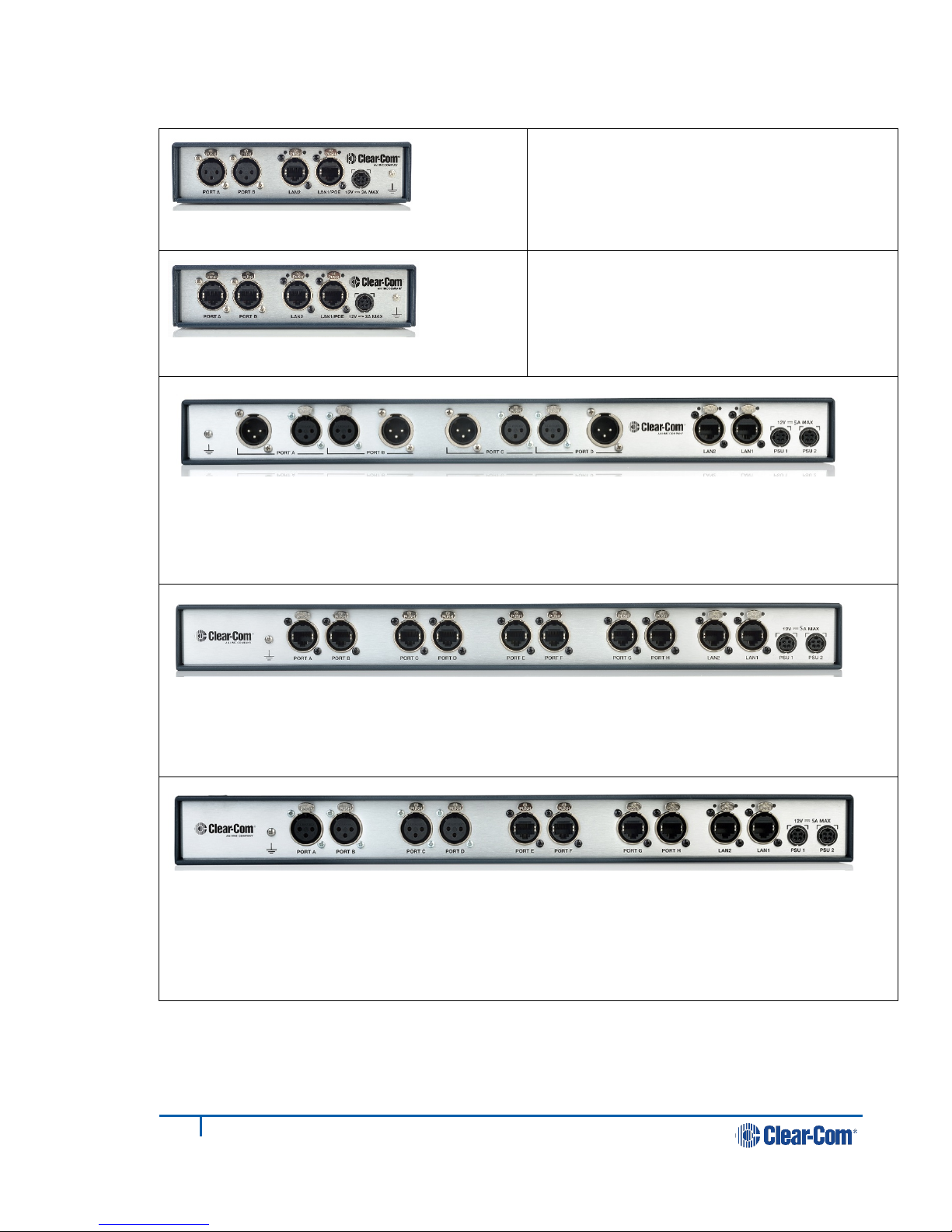
1.1 LQ and LQ-R models
LQ-2W2
Throw-down unit
Two 2-wire partyline connectors (XLR F)
LQ-4W2
Throw-down unit
Two 4-wire connectors (RJ45, etherCON)
LQ-R2W4 1 RU unit
Four 2-wire ports, each with a male and female connector. (XLR)
Dual redundant power supply connectors
LQ-R4W8 1 RU unit
Eight 4-wire connectors, (RJ45, etherCON)
Dual redundant power supply connectors
LQ-R2W4-4W4 1 RU unit
Four 2-wire connectors (XLR F)
Four 4-wire connectors (RJ45, etherCON)
Dual redundant power supply connectors
Page 9
9
399G116 Rev D
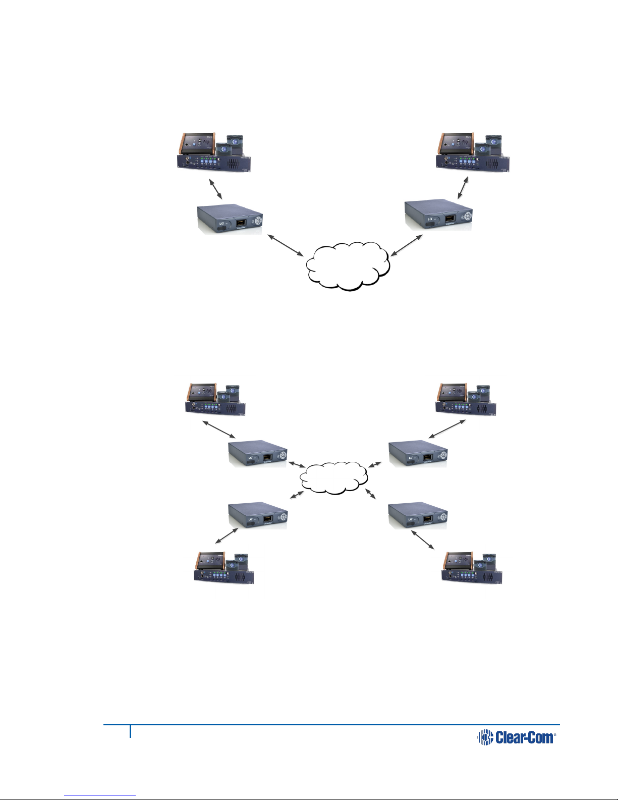
1.2 Basic example applications
LAN, WAN ,
Internet
LAN, WAN ,
Internet
Figure 1-1 Partyline to partyline (2-wire connection)
Figure 1-2 Partyline to partyline (2-wire connection). 8 ports,
2 per LQ unit
Page 10
10
399G116 Rev D
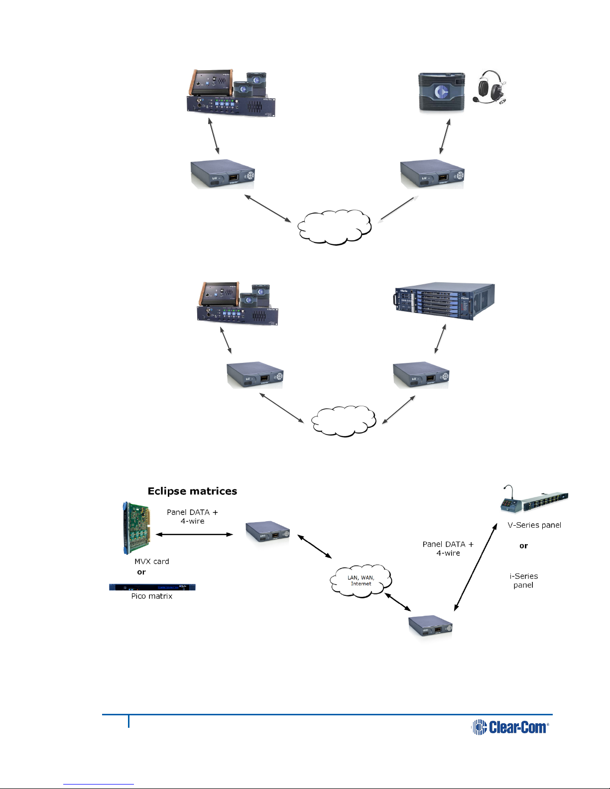
LAN, WAN ,
Internet
PoE or local
power
LAN, WAN ,
Internet
LQ 2W
LQ 4W
Figure 1-3 Partyline to beltpack
Figure 1-4 Partyline to matrix (2-wire to 4-wire)
Figure 1-5 Panel data over 4-wire connection. Replaces VoICE 2.0 product.
Note: Panel data is passed between a pair of LQ devices, providing a 4-wire direct
connection between two ports.
Page 11
11
399G116 Rev D
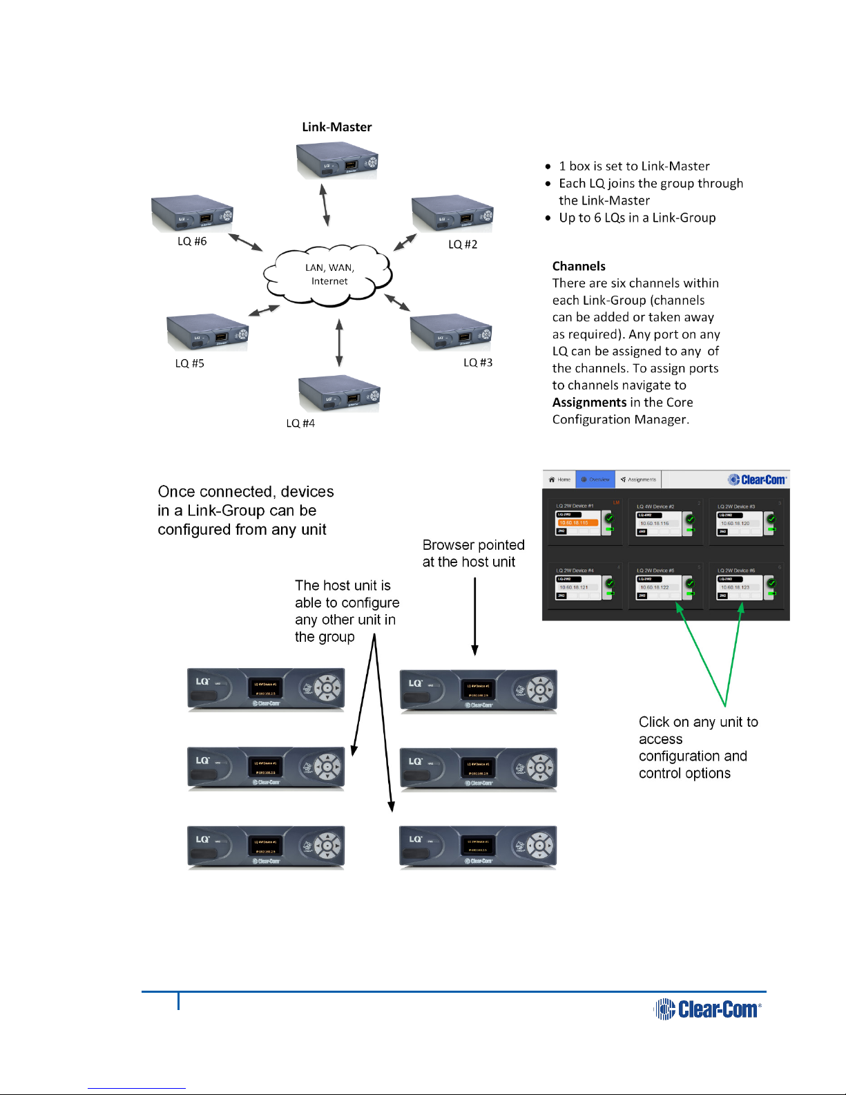
1.3 Link-Group
Figure 1-6 A Link-Group
Figure 1-7 Configuring a Link-Group from any device
Note: The Core Configuration Manager (the Web-based management interface) for any
unit can be reached either directly, by entering the IP address (displayed on the
front of the unit) into a browser address field or via the Overview page of any unit
in the Link-Group.
Page 12
12
399G116 Rev D
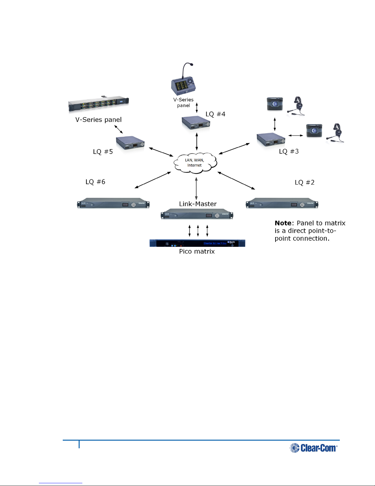
1.4 Example advanced application
Figure 1-8 Example application, partyline and 4-wire direct (panel data)
See 11.4 Example audio assignment via a Pico matrix for example audio
routes for this setup.
Page 13
13
399G116 Rev D
2 Basic setup (LAN)
LAN,WAN,
Internet
4-wire
2-wire
2.1 Setting up your LQ environment
Prepare your environment by gathering the following equipment:
• LQ units (LQ #1 and LQ #2)
• (2) provided power supply units (PSUs)
• (2) Straight-through Ethernet cables
• (1) Network connection with dynamic host control protocol (DHCP) server
present
• (2) 2-wire or 4-wire devices to provide an audio connection to each LQ
1) Using the Ethernet cable, connect LQ #1 to LQ #2 using either using either
LAN port on the rear of the unit.
2) Using another Ethernet cable, connect LQ #1 to your DHCP enabled network.
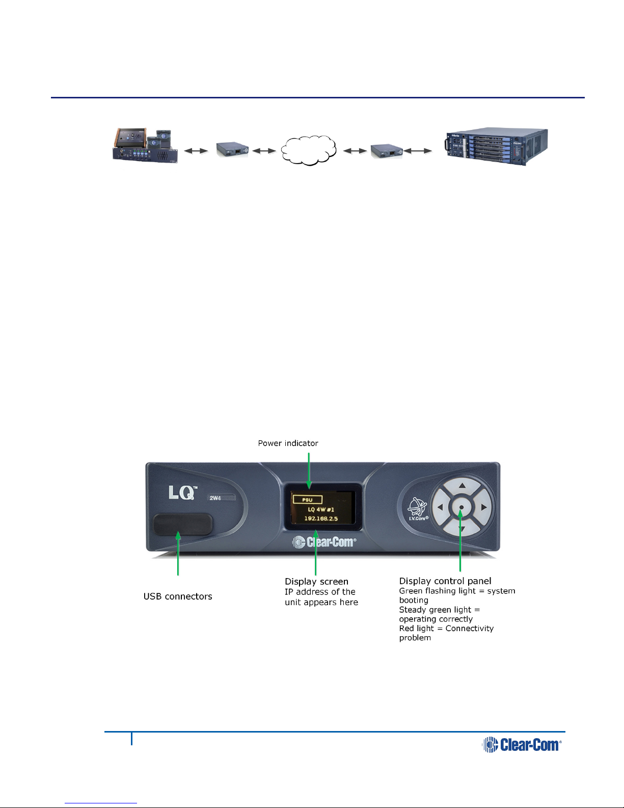
Figure 2-1 LQ device front panel display (4-Wire)
Note: The IP address will be allocated by DHCP (default mode). In the event
that the network does not serve DHCP or there is no network
connection, the IP address will revert to a link-local address. See 8
Link-local environments for more information.
Page 14

14
399G116 Rev D
3) Connect the provided PSU to each LQ device. Each device will display an IP
1. Connect LQ #1 to
LQ #2 using either
LAN port
LQ #1
LQ #2
2. Connect DHCP
enabled server to
either LAN port
3. Connect
power supply
4. Connect audio
equipment
address on the front panel display.
4) Connect audio equipment to Port A of each LQ device.
2.2 Accessing the Core Configuration Manager (CCM)
Note: Default username and password for the CCM: admin, admin.
Figure 2-2 Basic setup
From a computer, open a Web browser. Enter the IP Address as displayed on the
LQ #2 device in the address field of the Web browser (Chrome, Safari, Firefox, IE,
Opera). This takes you to the Core Configuration Manager.
Page 15
15
399G116 Rev D
Figure 2-3 Core Configuration Manager
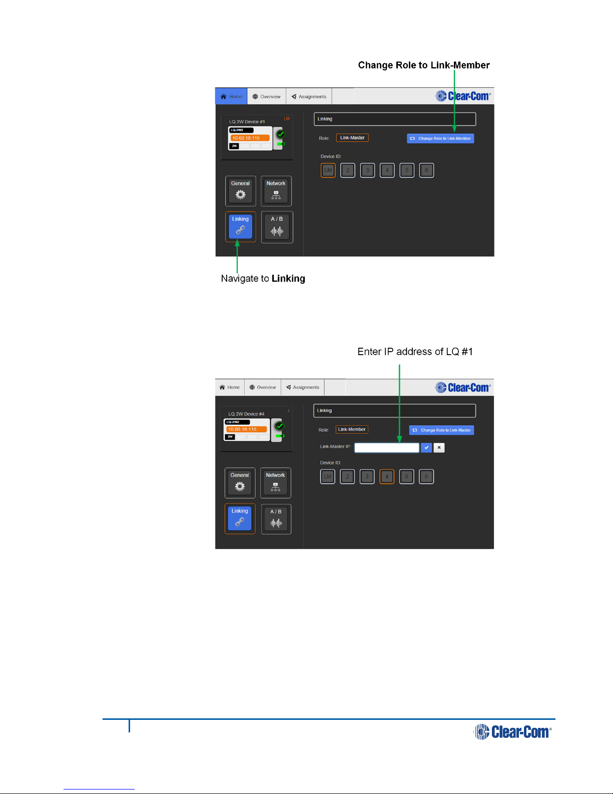
2.3 Create a Link-Group
Before linking units together, one LQ device must first be designated as the LinkMaster. This is accomplished by setting that device's role to Link-Master. Every
other LQ device within the Link-Group will then be set into a Link-Member role
which allows the linking of those units directly to the Link-Master.
In this example, LQ #1 will be left as Link-Master (default configuration) and LQ
#2 will be linked to it.
1) Navigate to Home > Linking on the CCM of LQ #2.
2) Click Change Role to Link-Member.
Page 16
16
399G116 Rev D
3) Within the Master IP address field, enter the IP address as displayed on the
LQ #1 device. Click on blue check mark or <ENTER> key to submit.
Page 17
17
399G116 Rev D
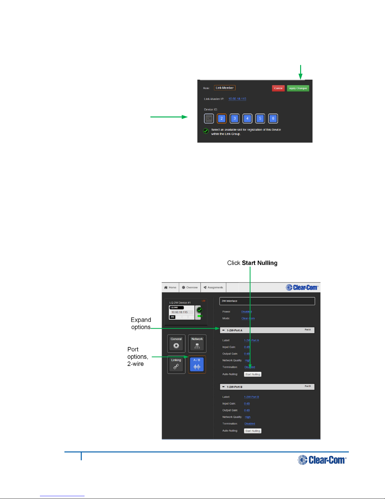
4) Select an available device ID (highlighted in blue).
Select an available device
ID (highlighted in blue)
Apply Changes
5) Click Apply changes.
LQ #1 and LQ #2 will now be linked.
6) Navigate to the Overview page (top navigation bar). Both LQ devices should
be displayed on this page.
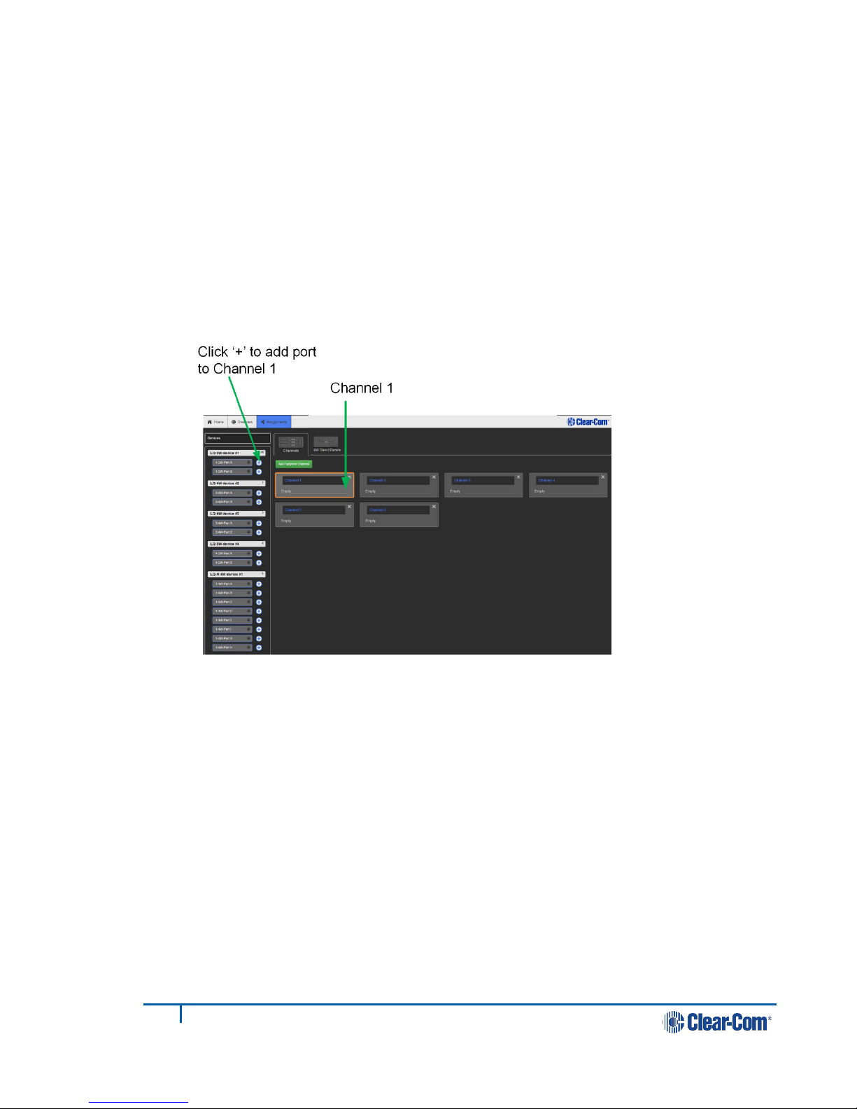
7) Before continuing, if either LQ device is a LQ-2W2 model, auto-null both
ports. For each device: within the General page, navigate to A/B.
8) Expand port sections (A and B) and click on the Auto-Nulling button for each
port.
Page 18
18
399G116 Rev D
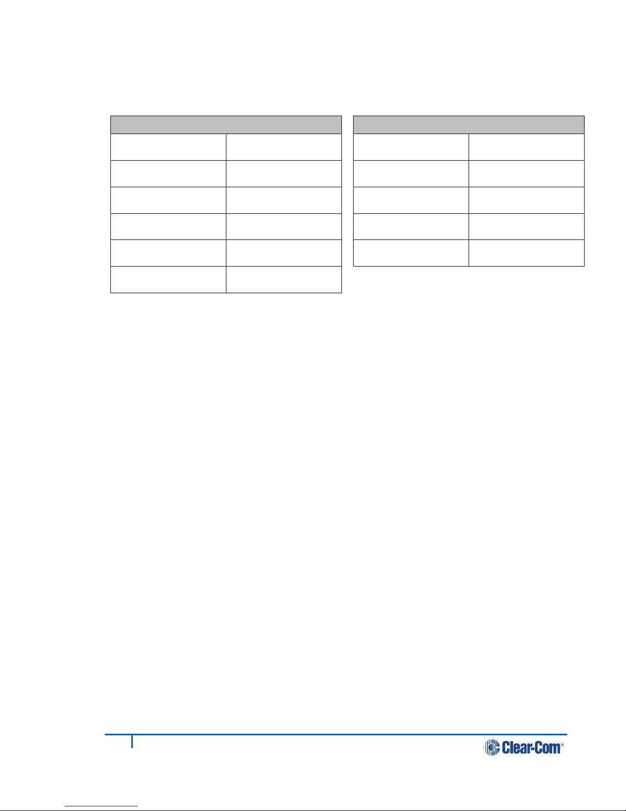
2.4 Assigning ports to a channel
1) Click on the Assignments button within the navigation bar.
2) Select the Channel tab.
3) Add Port A on each device to Channel 1 by clicking on the + symbol to the
right of each port.
You should now be able to pass audio and call/RMK signaling to/from Port A
on each device.
Note: Channel 1 must be selected before audio can be assigned to it. This is
shown by an orange highlight.
Page 19
19
399G116 Rev D
2.4.1 Interface port settings
From the LQ Core Configuration Manager go to Overview > A/B. The LQ factory
default settings are shown below.
2W
Power Disabled
Mode Clear-Com
Input/Output gain 0dB
VOX mode Disabled
Network quality High
Termination Disabled
4W
Input/Output gain 0dB
Network quality High
VOX mode Disabled
Port function To Matrix
Baud rate 19200 (Eclipse)
Page 20

20
399G116 Rev D
3 Powering your LQ™
Audio ports (2W or 4W)
LAN2 connector
LAN1/PoE connector
Sleeve-locking
power connector
Grounding screw
Figure 3-1 LQ unit rear panel (2-wire device)
3.1 Using the power supply unit (PSU)
• LQ units are supplied with a 24 watt sleeve-locking power connector.
• LQ-R 1RU units are supplied with two 60 watt sleeve-locking power
connectors. Use either power connector, or both to guard against one
power supply failing.
Note: When connecting the sleeve-locking power cable, be sure to push until the
connector locks into the device.
3.1.1 Understanding power display icons
You will be able to see the power status of your device is from:
• The front panel of the unit
• The device icon in the web based configuration tool (the CCM).
These indicators will show if the unit is using PoE or the PSU (LQ throw-down
units), and which of the two power supplies (or both) are in use for the LQ-R units.
Page 21
21
399G116 Rev D
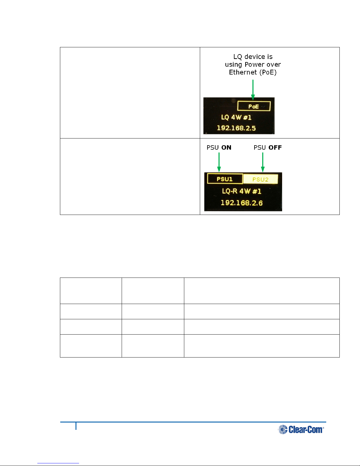
3.1.2 LQ Series front panel power display
LQ throw-down units
If the device is using the PSU, this will
be lit up instead of the PoE indicator.
LQ-R 1 RU units
3.1.3 Power 2-wire beltpacks from the partyline
2-wire partyline beltpacks take power from the partyline. The maximum numbers
are shown in the table below.
LQ series unit Power supply mA supplied to the 2-wire interface
(number of beltpacks powered by the
partyline)
LQ 24 watts 150 mA (~5 beltpacks)
LQ PoE 70 mA (~2 beltpack)
LQ-R 60 watts 250 mA (~10 beltpacks per pair of ports,
max 20 per device)
Page 22
22
399G116 Rev D
3.2 Using power over Ethernet (PoE) with 2-port units
The 2-port units will receive power from the LAN1/PoE connector if required (this is
not the case for the larger LQ-R units).
When using PoE the LQ-2W2 supplies approximately 70 mA of power to the 2-wire
interface.
Note: If you are powering more than two LQ devices from one PoE switch, please consult
the power output of the PoE switch, as you may reach the limits of its power
capacity with more than two boxes.
If this happens, the device(s) will show a persistent flashing green light, and not
move beyond the Clear-Com splash screen. This indicates that the device is
continually booting and needs more power than the PoE switch or network is
providing. In this case, consider using the supplied sleeve-locking power connector
cable to power the device.
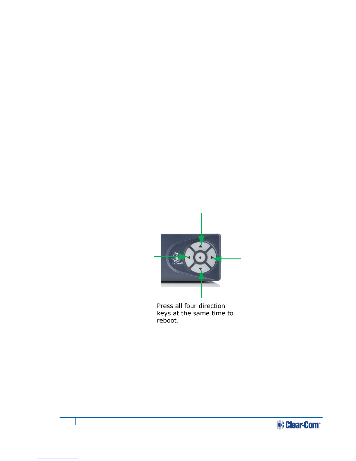
3.3 Re-boot system
The system will start its boot sequence immediately when power is applied. If you
need to reboot for any reason, either cycle the power or press all four direction
keys on the control panel on the front of the LQ unit at the same time.
Page 23

23
399G116 Rev D
4 Core Configuration Manager (CCM) walk-
through
LQ units can be configured and controlled from the Web-based Core Configuration
Manager. This includes all main functions:
• Linking units
• Network settings
• Port configuration
• Configuring of audio and signalization routing throughout the LQ-Group
• Adjusting network quality settings on a per port basis
• System monitoring and control
• Upgrading LQ units.
To access the Core Configuration Manager, enter the IP address of the LQ, as
displayed on the front panel, into the URL field of your browser. If the unit is
reachable over your network, this will take you to the Overview page of the CCM
that is served by the unit.
Note: Default username and password for the CCM: admin, admin.
4.1 Minimum requirements for the CCM
Supported on the latest versions of all major web browsers (i.e. Google Chrome,
Safari, Firefox, Internet Explorer).
Page 24
24
399G116 Rev D
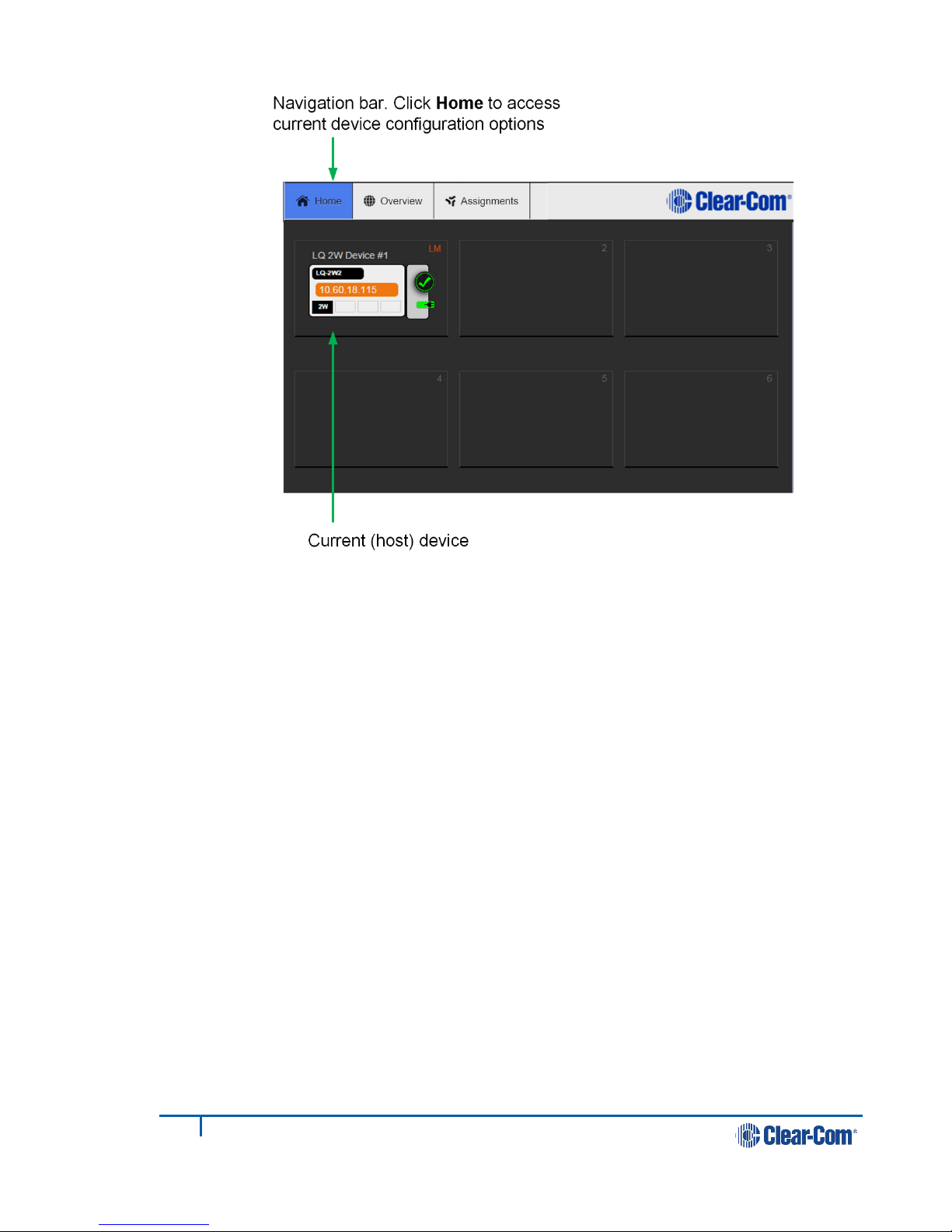
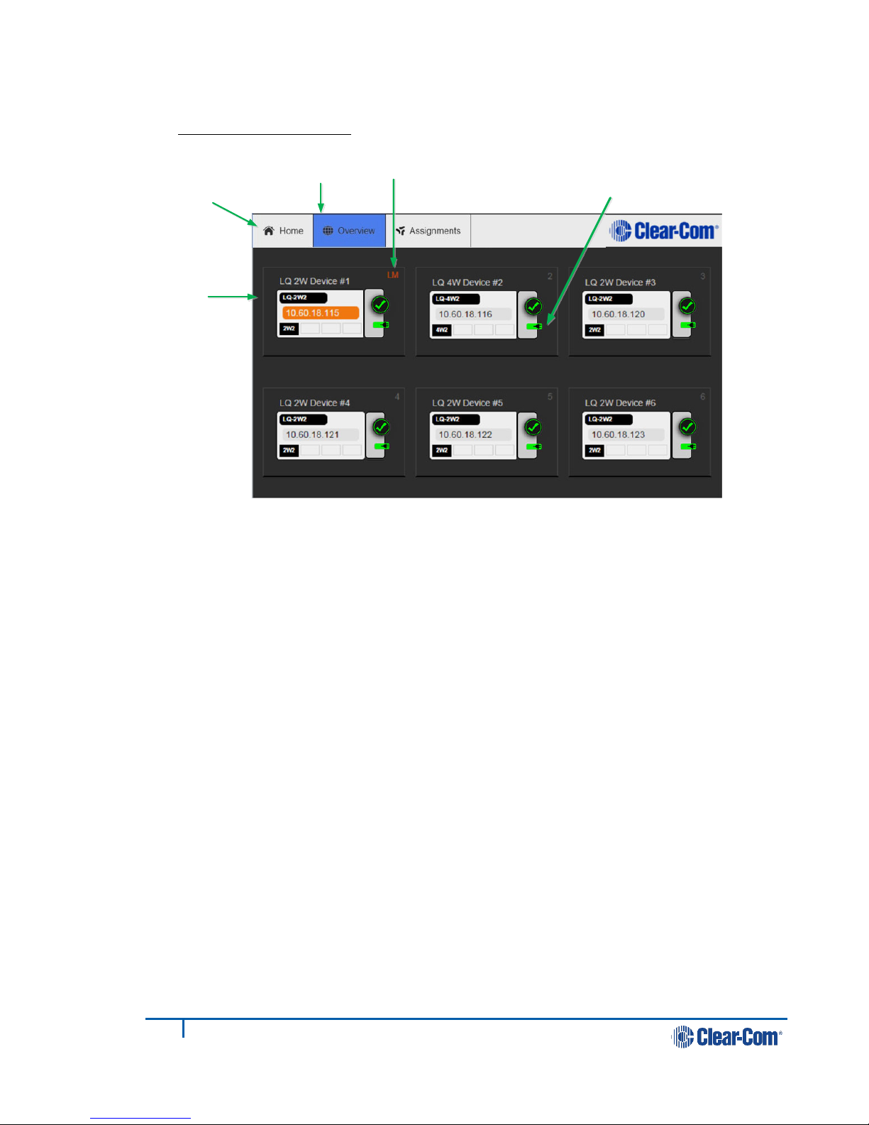
4.2 Overview page
Host device
(orange highlight)
Overview button
Note: The orange
highlight shows
which device the
browser is
currently
connected to.
Linked units appear in this screen
Navigation
bar
Link-Master
Power indicator
Figure 4-1 Overview page
Note: The Home button takes you to the General page of the device your browser is
Note: There is a navigation bar at the top of the page: Home, Overview,
Note: Please note that the device icon has a power indicator. See 3. Powering your LQ™
4.3 Device configuration
As LQ devices are added to the group, they will appear in this screen. To access
the configuration and control options for any one of the units in the group, click on
the device object.
connected to (the host device).
Assignments.
for more information on powering your device.
Once the units have joined a Link-Group, the devices can be configured either
directly or by proxy, meaning that the configuration operations for a unit are
routed through the host device. The host device is the unit which a browser is
currently directed to (see Figure 1-7 Configuring a Link-Group from any
device in Overview).
• The Home button will always take you to the host device’s configuration
page.
• Proxy configuration can be accomplished by clicking on any device within
the Devices page.
Page 25

25
399G116 Rev D
4.3.1 General page
From this page you can: re-name the device, identify the device’s model name and
software version, and access Upgrade, Change password and Maintenance
sections.
There are four buttons in the left margin, below the device image. These are:
General, Network, Linking and Port options, A/B. Port options will display
settings for 2-wire or 4-wire connections depending on the type of device you are
using. Click on a button to access a configuration page.
Figure 4-2 General page
4.3.1.1 Changing a device name from the General page
To change a device name, click on the existing name and enter a new one. Either
press the <ENTER> key or click the blue check mark to apply changes.
4.3.1.2 Upgrade
To upgrade your device, see 13 Upgrading your device.
4.3.1.3 Change password
Change the password to the Core Configuration Manager local to that device.
4.3.1.4 Maintenance
Reset the unit to factory settings, reboot the system or create a support archive in
this section.
Page 26

26
399G116 Rev D
Support Info provides a ‘snapshot’ of the device’s operational information for
troubleshooting purposes.
4.3.2 Network information page
The LQ unit’s network information is configured on this page.
4.3.2.1 DHCP or static IP allocation
DHCP is set by default and allows the device to automatically configure its network
information.
Figure 4-3 Network: DHCP mode
In some cases you may have to allocate the network information statically. See
Fig. 4-4 below.
Page 27

27
399G116 Rev D
For more information on external connectivity see 9 Network configuration.
For more information on static IP allocation see 9 Network configuration and 5
Linking.
4.3.3 Linking page
This is where the role of the LQ device is set to either Link-Master or, if connecting
to a Link-Group, Link-Member.
Each group must have a Link-Master, which is the default mode of operation.
Each Link-Member in the group must be linked to the Link-Master here.
To join a Link-Group:
1) Configure Link-Member role.
Figure 4-4 Network: static IP allocation
Page 28

28
399G116 Rev D
Figure 4-5 Linking: assign role to device
Note: The Change Role button toggles between Link-Member and Link-Master.
2) Query Link-Master for list of available Device IDs within the Link-Group.
Figure 4-6 Linking
3) Select one of the available Device IDs and click Apply Changes.
For more detail on the linking process see 2.3 Create a Link-Group.
For more on the Link-Master role and its effects see 5 Linking.
4.3.4 Port configuration
This is where you will configure the audio interface.
For more detail on port settings see 10 Interface port configuration.
Page 29

29
399G116 Rev D
Figure 4-7 Four-wire interface port settings
Click on a blue
option to
select it
4.4 Assignments page
Click Assignments on the top menu bar.
All devices joined to the Link-Group, along with their associated ports, appear in
the left margin of this page. You will also see two page tabs on the centre right of
the page; Partyline and 4-wire direct. Choose either tab, depending on whether
you wish to configure a virtual partyline channel or a 4-wire direct (panel)
connection.
4.4.1 Configuring a partyline channel
1) Select the Partyline tab.
The six customizable channels are shown in the main area of the page.
To associate a port to a channel:
2) Select the channel by clicking on it
3) Go to the devices in the left hand margin of the screen and add ports to a
channel by clicking ‘+’. See Figure 4-8.
You will see the assigned sources appear inside the allocated channel.
4) To remove a port from a channel click ‘-‘.
Note: A port can only be assigned to one channel at a time.
Page 30

30
399G116 Rev D
Port assignment status is represented by the following three colors:
• White: connected, audio is being transmitted
• Yellow: connection pending, connection status unknown
• Red: device is unreachable.
Note: If required, more channels can be added using the green ‘Add Channel’ button.
Figure 4-8 Assignments page
4.4.2 Configuring a 4-wire direct/panel
1) Select the 4W Direct/panel tab.
2) Click the green Add Direct Connection button. A direct connection box
appears on the page with an orange highlight to indicate that it is actively
selected.
To associate a port to a direct connection:
3) Make sure the direct connection box is selected (orange highlight). Click the
box to select if necessary.
Page 31

31
399G116 Rev D
4) Go to the devices in the left hand margin of the screen and add a port to a
direct connection by clicking ‘+’.
Note: You can only add a 4-wire source in this context.
5) Select the second source from the devices in the left margin and click ‘+’. This
source will also appear in the direct connection box and a connection will be
created between the two ports.
6) To remove a port from a direct connection click ‘-‘.
4.4.3 Changing channel/4-wire direct labels in the Assignments
page
To change the name of a channel or 4-wire direct connection:
1) Click on a blue channel/4-wire direct name.
2) Enter a new name into the white dialogue box and click the blue check mark
to apply changes.
Note: Channel and 4-wire direct names can only be modified when the Link-Master is
operational.
Page 32

32
399G116 Rev D
5 Linking
A Mesh Network
Link-Master
LQ #1
LQ #2
LQ #3
LQ #4
LQ #5
Once joined to the Link-Group, all devices attempt to connect to
all other devices within the group.
• Configuration and control of any device is possible through any
other unit in the group
• Configuration information is both distributed and persisted within
every node of the group
• Significantly reduces loss of service
5.1 A Link-Group
• A Link-Group can contain up to 6 LQ devices
• A Link-Group must have one unit designated as Link-Master
• The Link-Group performs a “best effort” approach to creating a mesh
network between all the devices within the group.
5.2 The Link-Master role
The Link-Master role serves three main purposes:
1) It facilitates Link-Group membership.
2) It is the owner of channel names, meaning that channel names will only
persist (be maintained consistently) if the Link-Master is operational.
3) It is responsible for the synchronization and distribution of both configuration
and device availability status throughout the Link-Group.
Figure 5-1 A mesh network
Page 33

33
399G116 Rev D
Note: The Link-Master must be reachable on TCP port 80 by all devices within the Link-
Link-Master
LQ #1
LQ #2LQ #3
Linking over a LAN
Link-Members #1,2,3
connect to the Link-Master.
The Link-Master IP is
entered in their Linking page
within the CCM.
Group. Reachability of the Link-Master on TCP/UDP port 655 facilitates the routing
of audio to/from the Link-Master but is not mandatory when setting up a LinkGroup.
Note: It is recommended that the IP address of the Link-Master is allocated statically.
When allocated by DHCP the IP address can change. If this happens the LQ devices
will no longer be able to reach the Link-Master device.
Note: Any device can be set to Link-Master mode which is the factory default setting.
5.3 The Link-Member role
LQ devices that are not designated master will have the role of Link-Member.
Joining a device to a Link-Group requires that device to be set to Link-Member role
which will prompt the user to enter the address of the Link-Master.
If a Link-Member device loses connection to its Link-Master, the front panel LED
will turn red until that connection is restored.
5.4 Linking units
The only way to join devices to a Link-Group is through the Linking page of the
CCM. Only the IP address of the Link-Master is required during this set up.
See 2.3 Create a Link-Group for detailed instructions.
5.5 Linking over a LAN
This is the simplest way to link devices together. This type of environment enables
the highest potential level of communication quality and the best availability of
resources.
Figure 5-2 Linking over a LAN
Page 34

34
399G116 Rev D
5.6 Linking over Internet or WAN
WAN or Internet
Link-Master internal IP: 192.168.1.100
Link-Master external IP: 34.50.16.7
Link-Master
LQ #1
LQ #2
External (public)
IP: 34.50.16.7
Link-Members are configured to
join the Link-Group using the
Link-Master's external IP and
management port.
You might have to use port-forwarding. See
7. Internet Connectivity for more
information.
Example port-forwarding at firewall:
Port 80 forwarded to 6300
Port 655 forwarded to 6301
When linking over Internet or WAN, the IP addressing of the units becomes more
complicated because the units use external addressing and port-forwarding to
navigate firewalls. The LQ units must be able to reach the Link-Master.
The Link-Master uses TCP port 80 for management and TCP/UDP port 655 for
audio. You will need to create port-forwarding rules within your firewall to make
these ports externally accessible to the Link-Master device.
The Link-Master’s external IP and port will need to be configured within the
Network page of the CCM.
Figure 5-4 External IP addressing of the Link-Master
Figure 5-3 Linking over WAN or Internet
Page 35

35
399G116 Rev D
Figure 5-5 Linking: external Link-Master IP address entered in Linking page of
member units
For more information on linking over the Internet, see 7 Internet connectivity.
5.7 How to remove a device from a Link-Group
5.7.1 Remove an on-line Link-Member from a group
1) Access the Core Configuration Manager for any device within the Link-Group.
2) In the Overview page, click on the device image of the unit that you wish to
remove from the group.
Page 36

36
399G116 Rev D
3) Navigate to Linking for that device.
4) Click Change Role to Link-Member.
5) Apply Changes.
The device will be reconfigured as a Link-Master and removed from the group.
5.7.2 Remove an off-line Link-Member from a group
1) Access the Core Configuration Manager for any device within the Link-Group.
2) In the Overview page, the off-line unit will show a red ‘X’. Click on this
device.
3) You will be asked if you want to remove this unreachable device. Click
Delete.
The device will be removed from the Link-Group. It will not be reconfigured as a
Link-Master.
Page 37

37
399G116 Rev D
6 Front panel interface walk-through
From the front panel of the LQ you can:
• Set audio configuration
o input gain
o output gain
• Set VOX configuration
o VOX
o Threshold
o Delay
• Set 2-wire specific settings
o Powering of the line
o Clear-Com/RTS mode
o Auto-nulling
o Termination
• Set 4-wire specific settings
o Port Function: set port function of Ethernet cable ‘to Matrix’ or ‘to
Panel’,
o Vox levels
o Baud rate
• Set device settings
o Brightness of OLED
o Screensaver time-out
o Reboot
o Reset-to-default
• Display only
o Networking: mode, IP, MAC.
Page 38

38
399G116 Rev D
Figure 6-1 Front panel menu
Page 39

39
399G116 Rev D
6.1 Administration
• Version
• Reboot
• Reset to factory default
6.2 Audio
Note: The parameters in bold are defaults.
2-wire port A/B 4-wire port A/B
• Auto-null > Start
• Line termination
o Enabled/Disabled
• Input gain
o -3 to +3 dB
• Output gain
o -3 to +3 dB
• Vox
o Disabled/Threshold/Adaptive
• Vox threshold
o -18 to -60 dB (default -40
dB)
• Vox delay
o 0.5 to 4 seconds
• Power of line
o Enabled/Disabled
• Port Function
o to Matrix/to Panel
• Input gain
o 12 to +12dB
• Output gain
o 12 to +12 dB
• Vox
o Disabled/Threshold/Adaptive
• Vox threshold
o 0 to -42 dB (default -22 dB)
• Vox delay
o 0.5 to 4 seconds
• Baud rate
o 9600 (Drake 4000)/19200
(Eclipse)
• Mode
o Clear-Com/RTS
Page 40

40
399G116 Rev D
6.3 Device
Note: The parameters in bold are defaults.
• OLED brightness
o Bright/Normal/Dim/Very Dim
• Screensaver
o 15/30/60/90/120 seconds
6.4 Networking (information display only)
• Mode > Static/DHCP
• IP address
• MAC address
Page 41

41
399G116 Rev D
7 Internet connectivity
External (public) IP
Link-Master
Link-Member
LAN,WAN,
Internet
All devices within a Link-Group must have connectivity to the Link-Master on TCP
port 80. When linking devices over the Internet, make sure that this connectivity is
stable. Internet connection to an LQ device requires special configuration within
your firewall (port-forwarding).
7.1 Getting an external IP address
When networking LQ devices over the Internet, an external IP address is required
as a first step in making sure Link-Members can reach the Link-Master. The
external (public) IP address must be static and non-changing. Normally an Internet
Service Provider (ISP) will provide external addressing in Dynamic Host
Configuration Protocol (DHCP) mode. This is not guaranteed to remain static but
instead will change periodically. This will cause linking issues as the LQ devices
will not be able to reach the master if the IP address changes. Therefore, it is
suggested that you purchase a static address from your ISP. Failure to do this
could result in a loss of service.
Note: Another alternative is to maintain DHCP addressing but use the Address
7.2 Port-forwarding
Reservation feature available in most managed routers. This will instruct the router
to allocate a specific DHCP address to an LQ device identified by its MAC address.
The unit’s MAC address can be retrieved through the LQ's front panel menu
.
In order to facilitate connectivity to an LQ unit that is behind a firewall, certain
ports need to be mapped from your firewall to the LQ device. This mapping will
forward traffic received on those ports from the Internet directly to the LQ unit.
• The Link-Group uses TCP port 80 for link initiation and Web management.
• All the units use port 655 (TCP and UDP) for group connectivity and audio
transmission.
Page 42

42
399G116 Rev D
7.3 How to configure the Link-Master to be externally
reachable
Both the external IP address and the audio port forwarded within the firewall will
need to be configured within the Link-Masters device configuration page.
7.3.1 Set Link-Master external IP address
1) Navigate to the Link-Master's network configuration page by clicking on the
Link-Master device in the Overview page and then the Network button.
2) Enter the external IP address which the Link-Master will be reachable from.
3) Enter the Port configured within the firewall that maps to the LQ device's
audio port (TCP/UDP: 655).
7.3.2 Link devices to the remote Link-Master
1) Join an LQ device to the Link-Group by entering the IP address of the device,
as displayed on the front panel, into your browser.
2) Navigate to the Linking page for that device and click Change Role to Link-
Member (if currently in Link-Master mode).
3) Enter the Link-Master's external IP address and management port using the
format [IP:Port].
Note: This must be the port that is mapped to port 80 within the firewall
Page 43

43
399G116 Rev D
34.50.16.7: 6300
Link-Master IP and
external port if
required.
4) If the Link-Master is reachable on its management port, the available device
IDs will be highlighted. Select one of the blue highlighted IDs and click Apply
Settings.
5) Once the devices are successfully linked, all Link-Members will appear within
the Overview page.
7.4 How to configure Link-Members to be externally
reachable
Clear-Com recommends that all units in a Link-Group are reachable over the
Internet. In some cases this will mean external (public) addressing of the LinkMembers in a group as well as the Link-Master. This prevents a loss of service if
the master is unobtainable for any reason and creates more efficient audio routing.
Setting an external IP and interface port on individual Link-Members will reduce
the risk of loss of connection if the Link-Master is unavailable.
Perform the following steps if connecting Link devices across more than two
firewalls:
1) Navigate to the Networking page on each Link unit and input the external IP
address and port number. See below for example IP addresses and portforwarding.
Page 44

44
399G116 Rev D
External IP:
34.50.63.7
External IP:
39.56.12.8
External IP:
36.40.16.3
Link-Master
LQ #2
LQ #3
Networking page
Internal IP:
192.168.10.4
External IP: 34.50.63.7
External port: 6301
Networking page
Internal IP: 192.168.0.1
External IP:36.40.16.3
External port: 6301
Linking page
Link-Master IP:
34.50.63.7:6300
Example port forwarding rules:
Port 6300 forwarded to port 80
Port 6301 forwarded to port 655
Networking page
Internal IP: 192.168.0.4
External IP:39.56.12.8
External port: 6301
Linking page
Link-Master IP:
34.50.63.7:6300
Note: The external port set on the Networking page is the interface port (655), in this
example port-forwarded to 6301.
Note: The external port set on the Linking page is the management port (80), in this
example port- forwarded to 6300.
Page 45

45
399G116 Rev D
8 Link-local environments
Ethernet cable
Link-local mode
• Any networked device will enter link-local mode if it is set
to DHCP and no DHCP server is detected on the network.
• If both the laptop and the LQ device are in DHCP mode,
they will revert to link-local when connected. This means
they can communicate with one another as they are both
on the same subnet (169.254.xx.xx).
8.1 What is link-local?
A link-local address is an IP address within the local segment of any network.
Routers do not pass information to these as link-local addresses are not
guaranteed to be unique beyond a single network segment. When first connected
to a network, your LQ device will attempt to get an IP address via Dynamic Host
Configuration Protocol (DHCP). If no DHCP server is available the unit will
automatically enter link-local IP mode. A link-local IP address will take the form:
169.254.xxx.xxx.
8.2 Accessing an LQ unit when in link-local mode
Note: The units will operate in link-local, but for optimum performance it is
To access the CCM of an LQ unit in link-local, you must connect to it from a PC that
is also in link-local mode.
Devices will revert to link-local mode if they are configured to DHCP and fail to find
a DHCP address on the network or device they are attempting to connect to. A PC
can be put into link-local mode by ensuring it is in DHCP mode and connecting it to
the LQ unit that is in link-local with a standard Ethernet cable. The PC will look for
a dynamically generated IP address (DHCP), and when it does not find one will
enter link-local mode automatically.
Once the PC is connected to the LQ and in link-local mode, you can connect to your
LQ unit by opening a browser window on the computer and inputting the unit’s IP
address (from the front panel display) into the address field. This takes you to the
Core Configuration Manager where you can configure the device as usual.
recommended that they are used with either static or DHCP network settings.
Page 46

46
399G116 Rev D
9 Network configuration
9.1 Dynamic host configuration protocol (DHCP)
configuration
The default method for LQ devices to obtain an IP address is DHCP and this is the
preferred method when setting up a Link-Group over a LAN.
Most networks allocate IP addresses using DHCP. The addresses provided are
dynamic and will change from time to time.
9.2 Static configuration
DHCP is not recommended for the Link-Master and is not recommended for units
linked to the master in some situations. An example of this is when the Link-Group
has to navigate 2 or more firewalls.
In these cases you will allocate the network settings statically. To do this, navigate
to: Device > Network in the Core Configuration Manager. See Fig. 9-1 below.
Figure 9-1 Core Configuration Manager, networking page
9.2.1 Netmask or subnet
The netmask or subnet divides the network into sectors for more efficient routing
and is required when allocating a static IP address to an LQ device.
Page 47

47
399G116 Rev D
9.2.2 Gateway
Entry of this setting is optional. You will use it if setting up a Link-Group to
navigate across subnets. If it is not explicitly stated, the system will revert to the
device IP address.
9.3 Configuring an external IP address
You will use an external or public IP address when routing LQ devices over firewalls
(this will almost always be the case when connecting over the Internet). A LinkMaster connected to devices beyond a firewall will always use an external IP
address and an external port. Link-Members will use external addressing and ports
if connecting over firewalls also. See 7 Internet connectivity for more detail on
external IP addresses and ports.
Page 48

48
399G116 Rev D
10 Interface port configuration
10.1 Maximize bandwidth efficiency and audio quality
In the port-settings page of the CCM (configuration manager) you can adjust
settings for each audio interface port within the Link-Group (up to 48 ports) on a
per-port basis. This allows you to take network quality into account and maximize
both audio quality and bandwidth efficiency.
Note: To minimize noise, use screened (shielded) cable when connecting 4-wire ports.
10.2 Call signaling and Remote Mic Kill (RMK)
Call signaling is automatic on all audio routes so a call signal can be routed to any
destination (2-wire or 4-wire).
rd
Note: Call signaling will be passed to some 3
be recognized.
RMK is supported and passed through to 2-wire participants only.
10.3 2-wire port options
Note: Default option is in bold.
party intercom equipment, but it may not
• Power: Disabled/Enabled
Enable power if you wish to power partyline beltpacks. See 3.1.3 Power 2wire beltpacks from the partyline
Note: Enabling power will enable termination by default.
• Mode: Clear-Com/RTS (default is Clear-Com)
Note: For specific pin-outs see 15 Technical specifications.
• Label: Clicking on a blue label header will allow you to change the name of
the port. Enter the new name and click the blue check mark to apply
changes.
• Input/Output gain: -3 to +3 dB
• Network Quality: Very Low/Low/Balanced/High/Very High/Custom
Note: The jitter buffer setting is designed to buffer audio received to prevent loss if there
is network jitter. Please note that the jitter buffer selection will directly affect the
latency. This is because the lower number in the jitter range represents the
amount of time the LQ unit will buffer audio before delivering it to the port. A
bigger jitter buffer setting will increase latency in milliseconds.
The Custom option within the Network Quality setting allows adjustment of the
jitter buffer setting independent of bit rate and packet size.
Page 49

49
399G116 Rev D
o Bitrate: 16, 32, 48, 64, 128 kbps
o Packet size: 5ms, 10ms, 20ms, 40ms, 60ms
o Jitter: (min – max) 200 – 1000ms, 100 – 500ms, 60 – 200ms, 40 -
100ms, 20 – 60ms, 5 – 60ms, to 3 – 60ms
• Vox: This setting maximises bandwidth efficiency by detecting when the
line is silent and not transmitting at those times. Choose from 3 different
settings:
o Disabled (default)
o Fixed Threshold (user specified)
Delay: 0.5 to 4.0 seconds
Threshold: -18 to -60 dB. Default -40 dB
o Adaptive threshold. This is the Opus Codec’s own silence suppression
(Discontinuous Transmission or DTX) mechanism. This option will
implement comfort noise when silence is detected.
• Termination: Disabled/Enabled
• Auto nulling option
Figure 10-1 2-wire port options
Page 50

50
399G116 Rev D
10.4 4-wire port options
Note: To minimize noise, use screened (shielded) cable when connecting 4-wire ports.
Note: Default option is in bold.
• Label: Clicking on a blue label header will allow you to change the name of
the port. Enter the new name and either press the <ENTER> key or click
the blue check mark to apply changes.
• Input/Output gain: -12 to +12 dB
• Network Quality: Very Low/Low/Balanced/High/Very High/Custom
Note: The jitter buffer setting is designed to buffer audio received to prevent loss if there
is network jitter. Please note that the jitter buffer selection will directly affect the
latency. This is because the lower number in the jitter range represents the
amount of time the LQ unit will buffer audio before delivering it to the port. A
bigger jitter buffer setting will increase latency in milliseconds.
The Custom option within the Network Quality setting allows adjustment of the
jitter buffer setting independent of bit rate and packet size.
o Bitrate: 16, 32, 48, 64, 128 kbps
o Packet size: 5ms, 10ms, 20ms, 40ms, 60ms
o Jitter: (min – max) 200 – 1000ms, 100 – 500ms, 60 – 200ms, 40 -
100ms, 20 – 60ms, 5 – 60ms, to 3 – 60ms
• Vox: This setting maximises bandwidth efficiency by detecting when the
line is silent and not transmitting at those times. Choose from 3 different
settings:
o Disabled
o Fixed Threshold (user specified)
Delay: 0.5 to 4.0 seconds
Threshold: 0 to -42 dB. Default -22 dB
o Adaptive Threshold. This is the Opus Codec’s own silence suppression
(Discontinuous Transmission or DTX) mechanism. This option will
implement comfort noise when silence is detected.
• Port Function (sets pin polarity of Ethernet cable): to Panel /to Matrix
• Baud rate
9600 (Drake 4000)/19200 (Eclipse)
Page 51

51
399G116 Rev D
Expand port
options
Click blue
option to
change
settings
Figure 10-2 4-wire port options
Page 52

52
399G116 Rev D
11 Assignments
Channel 1
LQ #1, Port A
LQ #2, Port A
Channels 1-6
• Point-to-multipoint routing of both audio and call
signaling
• Ability to mix 2W and 4W in one channel
• Channel operates as a virtual partyline
Link-Master
Channel 2
LQ #1, Port B
LQ #2, Port B
Link-Master, Port A
Link-Master, Port B
LQ #1
LQ #2
Audio can be assigned to either channels or 4-wire direct connections.
11.1 Channels
Note: A channel can be made up of multiple audio sources and routed anywhere
within a Link-Group.
Once connected to the units, audio from the input/output ports on the back of the
LQ devices can be assigned to any of the six available channels. The channels
operate as virtual partylines. When an audio route from a port is assigned to a
channel it will be able to talk and listen to any other ports assigned to that
channel.
11.1.1 How many channels can I use?
LQ series units can provide more than 6 channels. Use the green ‘Add Channel’
button on the Channel tab in the Assignments page of the Core Configuration
Manager (CCM) to add more channels. ‘
Figure 11-1 Audio channels in a Link-Group
Page 53

53
399G116 Rev D
11.1.2 Connecting ports
Click ‘+’ to
assign port to a
channel
1) Ensure that the ports are connected to the rear of the LQ unit.
2) From the Core Configuration Manager, navigate to Assignments.
3) Select the Channel tab on the Assignments page.
4) Click on the channel you want to assign a port to.
5) Navigate to Devices in the left hand margin of the screen.
6) Assign the required port to the channel by clicking ‘+’.
7) You will see the interface port appear inside the channel.
Page 54

54
399G116 Rev D
8) To unassign the port from the channel click ‘-‘ within the channel.
Figure 11-2 Assignments page
Note: A channel must be selected before ports can be assigned to it.
Note: A port cannot be assigned to a channel twice so it must be unassigned from a
channel as necessary before assignment.
11.1.3 Port availability status
Port assignment status is represented by the following three colors:
• White: connected, audio is being transmitted
• Yellow: connection pending, connection status unknown
• Red: device is unreachable
11.1.4 Audio indicator
On the Assignments page you will see an audio indicator on ports and channels.
This will light green when audio is flowing.
11.2 Audio configuration for a 4-wire direct/panel
connection
Note: Unlike an LQ channel, which can contain multiple audio sources, a 4-wire
direct/panel connection is between two ports. A 4-wire direct connection
cannot be included in a channel and is configured separately.
1) Ensure that the ports are connected to the rear of the LQ unit.
Page 55

55
399G116 Rev D
2) From the Core Configuration Manager, navigate to Assignments.
Click ‘+’ to
assign port to
Direct 1
Direct 1 has an orange
highlight. This shows
that it has been clicked
and is ‘selected’.
3) Select the 4-Wire Direct tab in the Assignments page.
4) Click on the Add Direct Connection button to create a new direct connection
box or select an existing direct connection box. Make sure the connection box
you wish to add a port to has an orange highlight to indicate that it is
selected.
5) Navigate to Devices in the left hand margin of the screen.
6) Assign the required port to the direct connection by clicking ‘+’.
7) You will see the interface port appear inside the direct box.
8) Repeat steps 5 and 6 to add a second port to the direct box, connecting the
ports within it.
9) To unassign the port from the direct connection click ‘-‘ within the direct box
icon.
Page 56

56
399G116 Rev D
Click ‘-‘ to
remove port
from Direct 1
Note: A 4-Wire Direct must be selected before ports can be assigned to it.
Note: A 4-Wire Direct cannot be assigned to a route twice so it must be unassigned from
a direct box as necessary before assignment.
11.2.1 Port availability status
Port assignment status is represented by the following three colors:
• White: connected, audio is being transmitted
• Yellow: connection pending, connection status unknown
• Red: device is unreachable
• If one of the devices is displaying three yellow dots, the connection is
pending.
11.3 Modifying a channel/4-wire direct label
Clicking on a blue channel/4-wire direct header will allow you to change the name
of the channel or direct. Enter the new channel/direct name and press <ENTER>
key or click the blue check mark to apply changes.
Figure 11-3 Modifying a channel/direct label
Page 57

57
399G116 Rev D
11.4 Example audio assignment via a Pico matrix
Figure 11-4 Example audio assignment
Note: A 4-wire direct connection is between two points. A channel can accommodate
many audio routes in a partyline.
Page 58

58
399G116 Rev D
12 Using LQ™ to interconnect equipment
When connecting LQ units to other Clear-Com products and third party intercom
systems please use the following guidelines:
Device type Which LQ
unit?
HelixNet HLI-4W2 LQ-4W2
LQ-R4W8
LQ-R2W4-4W4
HelixNet HLI-2W2
(Note: this
connection is not
preferred for
LQ-2W2
LQ-R2W4
LQ-R2W4-4W4
optimum audio
quality)
MVX-A16/Eclipse
Pico
LQ-4W2
LQ-R4W8
LQ-R2W4-4W4
Other matrices
rd
(3
party)
LQ-4W2
LQ-R4W8
LQ-R2W4-4W4
Port Function Supports
call
Panel
data?
signaling?
To panel Yes No
N/A Yes No
To matrix
Yes Yes
(Identified as a
CCI-22 see 12.3
below.)
To panel No No
Encore MS-702/4 LQ-2W2
Encore RS
Beltpack 1/2/3
LQ-R2W4
LQ-R2W4-4W4
LQ-2W2
LQ-R2W4
LQ-R2W4-4W4
N/A Yes No
N/A Yes No
Page 59

59
399G116 Rev D
Device type Which LQ
unit?
Port Function Supports
call
signaling?
Panel
data?
RTS 2-wire
equipment
LQ-2W2
LQ-R2W4
LQ-R2W4-4W4
HME DX210 LQ-4W2
LQ-R4W8
LQ-R2W4-4W4
LQ-2W2*
LQ-R2W4*
Tempest 2400 LQ-4W2
LQ-R4W8
LQ-R2W4-4W4
LQ-2W2*
LQ-R2W4*
N/A Yes, but
does not
pass call
signaling to
4-wire audio
routes.
To panel
Yes No
N/A
To panel
Yes No
N/A
No
FreeSpeak LQ-4W2
LQ-R4W8
LQ-R2W4-4W4
To panel
N/A
Yes** No
LQ-2W2*
LQ-R2W4*
V-Series panel
i-Series panel
LQ-4W2
LQ-R4W8
LQ-R2W4-4W4
To panel Yes Yes
• *This connection is not preferred for optimum audio quality. LQ-4W2 is
recommended.
• ** On a FreeSpeak Base station, only ports 3 and 4 pass call signaling.
Table 1 Interconnection guidelines
Page 60

60
399G116 Rev D
12.1 Connecting 2-wire equipment
Navigate to
Device > A/B
Enable/disable
power
Termination
Auto-null
Click ‘+’ to
expand port
options
When connecting 2-wire equipment the following functions should be taken into
consideration:
• Auto-null
Note: Every time equipment is changed on a 2-wire port you should auto-
null.
• Enable/Disable the partyline power
• Line Termination.
These functions can be found in the 2-wire port settings page of the CCM. Navigate
to Device > A/B on any unit in the Link-Group and click ‘+’ to expand options.
Equipment Port settings
Encore RS beltpack 701/2/3 Power: Enabled
Encore MS-702/4
Encore PK-7
Encore PS-702/4
Table 2 Interconnectivity port settings guidelines
Figure 12-1 2-wire port options
Termination: Enabled
Auto-nulling: Start auto-nulling
Power: Disabled
Termination: Disabled
Auto-nulling: Start auto-nulling
Page 61

61
399G116 Rev D
12.2 Connecting to 4-wire equipment
Note: To minimize noise, use screened (shielded) cable when connecting 4-wire ports.
12.2.1.1 Pin-out configuration
Pin-out configuration can be set on all LQ Series 4-wire interfaces. This is a
software switch that switches the configuration of the pins on the RJ45 etherCON
connectors, according to the device you are connecting to. See Table 1 above.
Pin-out configuration is set ‘to Matrix’ by default. To set the pin configuration of a
device:
1) Access the CCM for any unit in the Link-Group.
2) Navigate to Device > A/B and click ‘+’ to expand options.
3) Select either ‘to Matrix’ or ‘to Panel’ and either press the <ENTER> key or
click the blue check mark to submit changes.
Page 62

62
399G116 Rev D
12.3 Connecting an Eclipse Pico or MVX card to an
Encore device using LQ
Figure 12-2 Connecting an Encore device to a matrix over IP
When setting up this connection, care must be taken to configure the port in the
EHX software correctly. This is because, in this case, the port must be declared as
a CCI-22 device as the port detection device on the LQ will recognise it as such.
1) From the EHX software, navigate to EHX/System/Cards and Ports.
2) Select the MVX card port.
3) Select a CCI-22 device from the list.
4) It is advisable to label the port as an LQ 4-wire device to avoid confusion.
Page 63

63
399G116 Rev D
Note: The connection between the MVX or Pico and the LQ device is a 4-wire connection,
even though it is declared as a 2-wire connection.
See 5.16 Port Function in the Eclipse 8.5.1 EHX Software User Guide for more
information on port function.
12.4 Connecting an Eclipse Pico or MVX card to a panel
using LQ
When setting up this connection, the MVX port to the LQ should be declared as a
panel in the EHX software.
See 5.16 Port Function in the Eclipse 8.5.1 EHX Software User Guide for more
information on port function.
12.4.1 Setting pin configuration 4-wire ports
See 15 Technical specifications for pin-outs.
Page 64

64
399G116 Rev D
13 Upgrading your device
Expand Upgrade
option (click on ‘+’)
Click Choose File
and navigate to
upgrade file (.gz
extension)
When upgrade file is
loaded, Start Upgrade
will light up. When this
happens, click on it to
upgrade
Upgrades for your device will be available from the Clear-Com website.
http://www.clearcom.com
In order to upgrade your device, you will need to import the upgrade file provided
by Clear-Com into the device via the unit’s CCM (Core Configuration Manager). An
LQ unit must be upgraded from the host device (the device that the browser is
currently addressing). The units cannot be upgraded by proxy.
Note: All devices in a Link-Group MUST be running the same version of the software.
13.1.1 Import the upgrade file
1) Open a browser window and input the IP address of the device into the URL
field to access the CCM. The device IP can be found on the front display of the
unit when it is powered and booted.
2) Navigate to Home > General in the CCM.
3) Expand the Upgrade option (click on ‘+’).
4) Click Select File and navigate to the upgrade file (.gz extension). Select the
upgrade file to upload it.
5) When the upgrade file is loaded, Upgrade will light up. When this happens,
click on it to upgrade. When the upgrade is finished, the unit will reboot by
itself.
Note: If you downgrade an LQ unit from Version 2 to Version 1, you will see a red light
flashing on the front panel after the first reboot. Power cycle the unit one more
time to reset the status.
Figure 13-1 Upgrade your device
Page 65

65
399G116 Rev D
14 FAQs
14.1 How can I find the IP address or name of my LQ
unit?
The name and IP address of an LQ device can be found on the front panel display
of the units and also in the Web GUI. The IP address and name of a unit can only
be changed via the CCM (Web-based Core Configuration Manager).
14.2 What does a solid red light on the front panel
keypad indicate?
A solid red light on the keypad shows that the unit has lost its IP connection to the
Link-Master.
1) Make sure that the Link-Master’s IP address is reachable from the network
point where the Link-Member is connected.
14.3 What does a flashing red light on the front panel
keypad indicate?
A flashing red light shows that there is an ID conflict within the LQ-Group, meaning
that two LQ units are trying to connect to a Link-Group using the same link ID.
To resolve this you will need to undo the unit’s link to the Link-Master and then reapply the linking process to an available ID:
1) Within a Web browser, enter the IP address of the LQ device which is showing
the flashing red LED. This takes you to the Core Configuration Manager (CCM)
for that unit.
2) Navigate to the device’s Linking page (Home > Linking).
3) Click the Change Role to Link-Master button and click Apply Changes.
4) Now reconfigure the link and the link ID. To do this, click the Change Role to
Link-Member button, and enter the Link-Master IP. Click the blue check
mark or <Enter>.
5) Select an available ID slot (available IDs will be highlighted in blue) and click
Apply Changes.
Page 66

66
399G116 Rev D
14.4 What does a persistent flashing green light (more
than 2 minutes) on the front panel keypad
indicate?
The devices boot automatically when power is supplied and show a flashing green
light on the front panel keypad while the system is booting.
If the device is booting (the flashing green light does not turn into a solid green
light) for more than 2 minutes, and the display screen does not move beyond the
Clear-Com splash screen, the most likely explanation is that the unit does not have
enough power. This can happen if too many LQ devices are drawing power from
the same PoE switch or network.
Please check the power supply provided by PoE to see if this is the case and
consider using the supplied power connector cable to power the devices.
14.5 What types of 2-wire intercom do LQ Series units
support?
• Clear-Com
• RTS TW
14.6 Can I connect Clear-Com intercom panels to LQ 4wire devices?
Yes, Version 2 firmware and later supports Clear-Com Eclipse ECS/EHX matrix to
panel connections.
Matrix+3 connections are not supported.
Page 67

67
399G116 Rev D
14.7 How are LQ Series devices powered?
• LQ throw-down units use local power (24 watt sleeve-locking PSU) or
Power over Ethernet (PoE).
• LQ-R 1RU rack units use local power only (2 x 60 watt sleeve-locking
PSUs).
14.8 How do I update the software in the LQ units?
Connect a Web browser to the LQ unit and navigate to the Upgrade section within
the device configuration page (Home > General).
For more detailed information see 13 Upgrading your device.
14.9 How do I eliminate choppy audio being received by
another LQ unit?
Choppy audio is usually the result of a port that has a Network Quality setting that
is too high for the IP network. The following two approaches will help resolve this
issue:
14.9.1 Reduce the Network Quality setting on the transmitting LQ
unit’s port
1) Within a Web browser, enter the IP address of the LQ device which is
transmitting the audio to the receiving unit. This takes you to the Core
Configuration Manager (CCM) for that unit.
2) Navigate to the LQ unit’s audio interface configuration page (Home > 2-
Wire/4-Wire).
3) Click on the Network Quality setting for the appropriate port.
4) Choose a lower network quality setting and click on the clue check mark to
apply the setting.
5) Repeat step 4 until the choppy audio is minimized.
14.9.2 Reduce the Network Quality setting on the receiving LQ
unit’s port
To modify network quality on the receiving LQ unit’s port use the following steps:
1) Within a Web browser, enter the IP address of the LQ device which is
experiencing choppy audio. This takes you to the Core Configuration Manager
(CCM) for that unit.
Page 68

68
399G116 Rev D
2) Navigate to the unit’s audio interface configuration page (Home > 2-
Wire/4-Wire).
3) Click on Network Quality for the appropriate port.
4) Choose a lower Network Quality setting and click on the blue check mark to
apply the setting.
5) Repeat step 4 until the choppy audio is minimized.
Note: The jitter buffer setting is designed to buffer audio received to prevent loss if there
is network jitter. Please be aware that the jitter buffer selection will directly affect
the latency. This is because the lower number in the jitter range represents the
amount of time the LQ unit will buffer audio before delivering it to the port. A
bigger jitter buffer setting will increase latency in milliseconds.
The Custom option within the Network Quality setting allows adjustment of the
jitter buffer setting independent of other settings.
14.10 How do I set the system up if I have to cross one
or more firewalls?
As a minimum requirement for connectivity, the Link-Master must be reachable by
all other Link-Members in the Link-Group. To achieve this, port-forwarding rules
need to be created within the firewall which the Link-Master is behind. The ports
that need to be forwarded are as follows:
1) 80:TCP. This is used for both link initiation and Web management.
2) 655:TCP/UDP. This is used for the transmission of all audio and data (call
signaling) between Link-Group members.
To set up a Link-Group with devices behind one or more firewalls, please observe
the following example configuration:
Assume the following IP addresses and port-forwarding rules:
• 173.194.121.48 (external IP address)
• 192.168.1.100 (Link-Master network address)
• 6300 (arbitrary port chosen for port 80,the management port-forward
rule)
• 6301 (arbitrary port chosen for port 655, the audio/data port-forwarding
rule)
1) Within the firewall, create a port-forward rule that forwards any TCP requests
received on 173.194.121.48:6300 to 192.168.1.100:80.
Page 69

69
399G116 Rev D
2) Within the firewall, create a port-forward rule that forwards any TCP/UDP
requests received on 173.194.121.48:6301 to 192.168.1.100:655.
3) Within the Link-Master’s Network configuration page, configure the external
IP and audio/data port:
4) Within the remote unit’s Linking configuration page, configure the LinkMaster’s external IP and management port:
5) Repeat step 4 for each LQ unit to be part of the group.
6) For every Link-Member within the Link-Group that can be made externally
reachable, navigate to the device’s Network configuration page and
configure the external IP and audio/data port as in step 3 (optional).
These configuration steps will ensure basic connectivity within the Link-Group. For
more detailed information see 7 Internet connectivity.
14.11 Why does the Link-Master need to have a static IP
address?
The Link-Master needs to be statically addressed in order to prevent its IP address
from changing. A changed IP address will result in loss of connectivity with the rest
of the Link-Group.
Note: Another alternative is to maintain DHCP addressing but use the Address
Reservation feature available in most managed routers. This will instruct the router
to allocate a specific DHCP address to an LQ device identified by its MAC address.
The unit’s MAC address can be retrieved through the LQ's front panel menu
.
14.12 What are the consequences if connection to the
Link-Master is lost?
• Loss of audio. When connecting over the Internet, it is usually the case that
the Link-Master is the only device that is reachable by the other units in the
group. If this is the case, all audio will be routed through the Link-Master,
creating the possibility of a single point of failure. To prevent this, be sure
to facilitate connectivity between the LQ units in the group through portforwarding, described in 7 Internet connectivity.
Page 70

70
399G116 Rev D
• Prevents the ability of any of the LQ units to modify the name of any of the static
LAN, WAN ,
Internet
LQ 2W
LQ 4W
channel names.
• Prevents the distribution of device configuration changes throughout the Link-Group
resulting in the possibility of having an inconsistent view of that configuration
information depending on the perspective from which the device information is
retrieved.
14.13 Does the LQ-4W2 pass call signaling?
Yes, but only call signaling originating from Clear-Com equipment. Call signalling to
RTS equipment will be limited.
14.14 Can I link LQ-2W to an LQ-4W?
Yes, a 2-wire device can be linked to a 4-wire device.
14.15 Connectivity, including Web access to my LQ unit is
intermittent, even though I am accessing it from
within the same LAN.
The most probable cause for this is that an IP conflict exists. In this case, the IP
address used by the LQ unit is already in use by another device within your LAN.
The quickest and easiest way to check if this is the problem is to change the LQ
unit’s IP address to an address that is known to be available and observe if
connectivity to the unit is once again consistent.
Page 71

71
399G116 Rev D
15 Technical specifications
RTS
On-Noise
<-70dBu
Noise
<-75dBu
Pin
Clear-Com
RTS
Pin 1
Ground
Ground
Pin 3
Duplex audio
Duplex audio 2
15.1.1 Audio
Audio
2-wire LQ 4-wire LQ
Frequency
response
50-10 kHz Frequency
response
100-12 kHz
Codec OPUS Codec OPUS
Input/output gain -3 to +3 dB Input/output gain -12 to +12 dB
Maximum input
Clear-Com
Maximum input
0dBu (nominal
-18dBu)
+6dBu (nominal -
12 dBu)
Input impedance 100K transformer
isolated
Output impedance 120R transformer
isolated
Termination 200R selectable Maximum output +18dBu (nominal
0dBu)
Off-Noise <-85dBu
Call drive voltage
Call sense voltage
>11V
<4V
Call drive and
sense
Clear-Com
Clear-Com
Call drive voltage
Call sense voltage
-7dBu 20kHz
-32dBu 20kHz
RTS
RMK (Remote
microphone kill)
15.1.2 Pin-outs 2-wire
Pin 2 DC power
Clear-Com and
RTS
(30V)
DC power (30V)
Duplex audio 1
Page 72

72
399G116 Rev D
15.1.3 Pin-outs 4-wire
Pin 2
RS-422 input – (into matrix)
RS-422 output - (from panel)
Pin 3
Audio input + (into matrix)
Audio output + (from panel)
LQ-R: DC power connector (12V PSU)
26V 250mA max
128 kbps
Pin To panel To matrix
Pin 1 RS-422 input + (into matrix) RS-422 output + (from panel)
Pin 4 Audio output + (from matrix) Audio input + (into panel)
Pin 5 Audio output – (from matrix) Audio input – (into panel)
Pin 6 Audio input – (into matrix) Audio output – (from panel)
Pin 7 RS-422 output + (from matrix) RS-422 input + (into panel)
Pin 8 RS-422 output – (from matrix) RS-422 input – (into panel)
15.1.4 Partyline output current (2-wire)
Line voltage (selectable)
LQ: PoE 26V 70mA max
LQ: DC power connector (12V PSU) 26V 150mA max
15.1.5 Network quality settings
Note: Default option is in bold.
Bitrates 16, 32, 48, 64,
Packet size 5, 10, 20, 40ms,
60ms
Jitter buffer 200 – 1000ms,
100 – 500ms
60 – 200ms,
40 - 100ms,
20 – 60ms,
5 – 60ms,
0 – 60ms
Page 73

73
399G116 Rev D
15.1.6 Connectors
2-wire (LQ-2W2) 4-wire (LQ-4W2)
LQ Throw Down Units
2 x etherCON (F) : network
2 x 3 pin XLR-F: audio
2-wire (LQ-R2W4) 4-wire (LQ-R4W8) Combined (LQ-
2 x etherCON (F) : network
4 x 3 pin XLR-F
4 x 3 pin XLR-M
15.1.7 Power supply
LQ-R Rack Units LQ Throw Down Unit
Input: 100-240V, 47-63Hz, 0.58A max
Output: DC 12V, 2A, 60W max
2 x Plug-in adapter with sleeve locking
connector
US,UK, Europe, AUS and China sockets
included
4 x etherCON (F): 2 for network, 2 for
audio
LQ Rack Units
2 x etherCON (F) : network
8 x etherCON RJ45 F
Input: 100-240V, 47-63Hz, 0.58A max
Output: DC 12V, 2A, 24W max
1 x Plug-in adapter with sleeve locking
connector
US,UK, Europe, AUS and China sockets
included
R2W4-4W4)
2 x etherCON (F) :
network
4 x etherCON RJ45 F
4 x 3-pin XLR-F
15.1.8 Environmental
Operating temperature 32 - 104°F (0 - 40°C)
Storage temperature -67 - 158°F (-55 - 70°C)
Humidity 90% non-condensing
15.1.9 Dimensions and weight
LQ Throw Down Unit LQ-R Rack Unit
Dimensions 6.8w x1.79h x 8.45d
inches
(173 x 46 x 215 mm)
Weight 1.83lbs (.83kg) 4.29lbs (1.95kg)
19w x1.79h x 8.8d
inches
(484 x 46 x 224 mm)
Page 74

74
399G116 Rev D
16 Terminology/glossary
4-wire direct A 4-wire connection is characterised by two pairs of twisted
copper wire which transmit in opposite directions. A 4-wire
circuit gives a full-duplex interface which is often used to
connect to 3
4-wire direct connection (as opposed to a channel) provides
point-to-point and panel connections over IP. The 4-wire
direct interface will pass panel data as well as audio. 2-wire
connections are inactive in the 4-wire direct tab of the
Assignments page in the CCM and cannot be used in this
context.
CCM Core Configuration Manager. This is the Web-based
configuration tool that each LQ device is supplied with. It can
be accessed by entering the IP address of your device (shown
on the device front panel) into the URL field of a Web
browser.
Channel In the context of the LQ product, a channel represents a
virtual party or conference line. A channel comprises audio
from audio interfaces on the devices (ports A & B and A-F)
that have been assigned to that channel. Within a channel, all
parties can hear and speak to each other.
rd
party devices. When used with the LQ Series, a
Host device The LQ device whose Web-based configuration tool (CCM)
your browser is currently directed to.
Linking The act of joining multiple LQ devices together in one group.
Link-Group A set of devices linked together forming their own isolated
network.
Link-Master Role of a device within a Link-Group that provides central
reachability within the group as well as ownership of both
configuration and distribution of information.
Link-Member Role of a device within a Link-Group that shares client
privileges within the group.
Partyline In a partyline, all the participants on the line are involved in
the same conversation, they can hear and talk to all
members. In some contexts a partyline is known as a
conference line. Partylines can be 2-wire or 4-wire.
Page 75

75
399G116 Rev D
Proxy device A device within a Link-Group that can be configured via the
Web-based configuration tool (CCM) of another unit in the
group.
Virtual partyline A virtual partyline is a digital audio channel that is made up
of several different audio sources. In terms of audio, a virtual
partyline behaves in the same way as a partyline; all
participants can hear and talk to each other.
Page 76

76
399G116 Rev D
17 Compliance
FCC notice
This device complies with Part 15 of the FCC rules. Operation is subject to the
following two conditions: (1) This device may not cause harmful interference, and
(2) This device must accept any interference received, including interference that
may cause undesired operation.
NOTE: This equipment has been tested and found to comply with the limits for a
Class A digital device, pursuant to Part 15 of the FCC rules. These limits are
designed to provide reasonable protection against harmful interference when the
equipment is operated in a commercial environment. This equipment generates,
uses and can radiate radio frequency energy and, if not installed and used in
accordance with the instruction manual, may cause harmful interference to radio
communication. Operation of this equipment in a residential area is likely to cause
harmful interference, in which case the user will be required to correct the
interference at his own expense.
Changes or modifications not expressly approved by Clear-Com, LLC, an HM
Electronics, Inc. company could void the user’s authority to operate this
equipment.
Industry Canada Compliance Statement
This Class[A] digital device complies with Canadian ICES-003.
Avis de conformité à la réglementation d'Industrie Canada
Cet appareil numérique de la class[*] est conforme à la norme NMB-003 du
Canada.
Korean notice
A급 기기 (업무용 방송통신기자재)
이 기기는 업무용(A급)으로 전자파적합기기로
서 판매자 또는 사용자는 이 점을 주의하시기
바라며, 가정외의 지역에서 사용하는 것을 목
적으로 합니다.
LQ Series products comply with the following specifications:
EN55022 Emissions
EN55024 Immunity
Electromagnetic Compatibility Directive 2004/108/EC
Low Voltage Directive 2006/95/EC
IEC60950-1
Page 77

77
399G116 Rev D
Warning:
This is a Class A product. In a domestic environment this product may cause radio
interference in which case the user may be required to take adequate measures.
Waste Electrical and Electronic Equipment (WEEE)
The European Union (EU) WEEE Directive (2002/96/EC) places an obligation on
producers (manufacturers, distributors and/or retailers) to take-back electronic
products at the end of their useful life. The WEEE Directive covers most Clear-Com
products being sold into the EU as of August 13, 2005. Manufacturers, distributors
and retailers are obliged to finance the costs of recovery from municipal collection
points, reuse, and recycling of specified percentages per the WEEE requirements.
Instructions for Disposal of WEEE by Users in the European Union
The symbol shown below is on the product or on its packaging which indicates that
this product was put on the market after August 13, 2005 and must not be
disposed of with other waste. Instead, it is the user’s responsibility to dispose of
the user’s waste equipment by handing it over to a designated collection point for
the recycling of WEEE. The separate collection and recycling of waste equipment at
the time of disposal will help to conserve natural resources and ensure that it is
recycled in a manner that protects human health and the environment. For more
information about where you can drop off your waste equipment for recycling,
please contact your local authority, your household waste disposal service or the
seller from whom you purchased the product.
Figure 17-1: WEEE Symbol
 Loading...