

Page 1
User Guide
LQ 4.0 User Guide
Part Number: 399G227 Rev B
Date: September 07, 2017
Page 2

User Guide| LQ Series 4.0
Document reference
LQ Series 4.0 User Guide
399G227 Rev B
Legal disclaimers
Copyright © 2017 HME Clear-Com LtdHME Clear-Com Ltd
All rights reserved
Clear-Com, the Clear-Com logo, and Clear-Com Concert are trademarks or
registered trademarks of HM Electronics, Inc.
The software described in this document is furnished under a license agreement
and may be used only in accordance with the terms of the agreement.
The product described in this document is distributed under licenses restricting its
use, copying, distribution, and decompilation / reverse engineering. No part of this
document may be reproduced in any form by any means without prior written
authorization of Clear-Com, an HME Company.
Clear-Com Offices are located in California, USA; Cambridge, UK; Dubai, UAE;
Montreal, Canada; and Beijing, China. Specific addresses and contact information
can be found on Clear-Com’s corporate website: www.clearcom.com
Clear-Com contacts:
Americas and Asia-Pacific Headquarters
California, United States
Tel: +1 510 337 6600
Email: CustomerServicesUS@clearcom.com
Europe, Middle East, and Africa Headquarters
Cambridge, United Kingdom
Tel: +44 1223 815000
Email: CustomerServicesEMEA@clearcom.com
China Office
Page 2
Beijing Representative Office
Beijing, P.R. China
Tel: +8610 65811360/65815577
Page 3

User Guide| LQ Series 4.0
Table of contents
1 Overview 8
1.1 About LQ 8
1.2 The LQ product line offers: 8
1.3 2-wire features 9
1.4 4-wire features 9
1.5 4-wire + GPIO features 9
1.6 Example applications: 2-wire connections 10
1.7 Example applications: LQ to matrix connections 11
1.8 Example applications: Radio connections (GPIO) 14
1.9 LQ and LQ-R series models 16
2 Powering your LQ 19
2.1 Using the power supply unit (PSU) 19
2.2 Using Power over Ethernet (PoE) with 2-port units 20
2.3 Power 2-wire beltpacks from the Partyline 21
2.4 Reboot system 21
3 Core Configuration Manager (CCM) walkthrough 22
3.1 How to Access the Core Configuration Manager (CCM) 22
3.2 Overview 22
3.3 Device 25
3.4 Network 27
3.5 Linking 28
3.6 Ports 31
3.7 Roles 39
3.8 Assignments 40
3.9 Accounts 43
4 Basic set up (LAN) 45
4.1 Setting up your LQ environment within a LAN 45
4.2 Creating a Link-Group 48
Page 3
4.3 Using Channels to route audio 51
5 Front panel interface 53
5.1 How to access front panel menu options. 54
5.2 Programming network details from LQ device front screen 54
6 Linking 57
6.1 What is a Link-Group? 57
Page 4

User Guide| LQ Series 4.0
6.2 About Linking 58
6.3 The Link-Master role 59
6.4 The Link-Member role 60
6.5 How to link LQ units over a firewall 61
6.6 How to remove a device from a Link-Group 63
7 About Channels and using them to route audio 64
7.1 About Channels 64
7.2 Channel or 4-wire direct? 65
7.3 How many Channels can I use? 65
7.4 Connecting audio sources and routing them 66
7.5 Audio configuration for a Direct connection 67
7.6 Changing a Channel label 68
8 Interface port configuration 71
8.1 Call signaling and Remote Mic Kill (RMK) 71
8.2 2-wire specific port options 71
8.3 4-wire specific port options 71
8.4 4-wire + GPIO specific settings 72
8.5 GPIO action triggers (4-wire + GPIO and IVC-32 ports) 72
8.6 IVC-32 specific port settings 72
8.7 Port settings 73
8.8 VOX (audio-gating) 73
9 Network settings (IP) 74
9.1 Dynamic Host Configuration Protocol (DHCP) 74
9.2 DHCP or Static IP addressing? 74
9.3 Static IP configuration 74
9.4 Link-local environments 76
9.5 Accessing an LQ unit when in link-local mode 76
10 Internet connectivity 78
10.1 Port-forwarding 78
11 Clear-Com Eclipse matrix connections 79
Page 4
11.1 How to create virtual ports and connect to a matrix 79
12 What are Networked Control Events and how do I use them? 83
12.1 About Networked Control Events 83
12.2 How to set up Networked Control Events 83
12.3 Examples of when to use Networked Control Events 86
Page 5

User Guide| LQ Series 4.0
12.4 Types of GPI (input) trigger 89
12.5 GPIO port pinout 90
12.6 GPIO: Examples and step-by-step set up 91
13 Session Initiation Protocol (SIP) connectivity 98
13.1 What is SIP? 98
13.2 Examples of LQ-SIP 98
13.3 LQ-SIP standalone 98
13.4 LQ-SIP and Clear-Com Eclipse matrix systems 100
13.5 Connecting matrix systems using LQ-SIP (long range) 101
13.6 Program LQ-SIP standalone 101
13.7 Program LQ-SIP and Clear-Com Eclipse 107
13.8 How to use SIP calls 116
Line Release option (MVX card) 118
Off-Hook Tally (IVC card) 119
13.9 SIP and the Internet 120
14 LQ to HelixNet connectivity 123
14.1 HelixNet/LQ Link-Group 123
14.2 Connecting HelixNet and LQ with analog connection 125
14.3 Programming a HelixNet/LQ Link-Group 125
15 Agent-IC and LQ 131
15.1 Agent-IC Profiles 131
15.2 Agent-IC Roles 131
15.3 Agent-IC default Role 132
15.4 Change Agent-IC default Role configuration 133
15.5 Program Agent-IC to LQ connectivity 135
16 Licensing 138
16.1 Add licenses online 138
16.2 Add licenses offline 139
17 Using LQ to interconnect equipment 141
Page 5
17.1 Connecting 2-wire equipment 143
17.2 Connecting to 4-wire equipment 144
17.3 Connecting an Eclipse PiCo (or MVX card) to an Encore device using LQ 145
17.4 Connecting an Eclipse PiCo (or MVX card) to a panel using LQ 146
17.5 PiCo HX trunk to HX matrix (Eclipse HX 8.7 and above) 147
Page 6

User Guide| LQ Series 4.0
18 Upgrading your device 148
18.1 Import the upgrade file 148
19 FAQs 150
19.1 Device queries 150
19.2 2-wire and 4-wire specific queries 151
19.3 Interconnection queries 152
19.4 IP and network queries 159
19.5 Audio quality queries 165
19.6 Telephony queries 169
20 Technical specifications 172
20.1 System limits and capacities 172
20.2 Audio 173
20.3 Pinouts 173
20.4 4-wire pinouts 174
20.5 Partyline output current (2-wire) 175
20.6 Network quality settings 176
20.7 Connectors 176
20.8 Power supply 177
20.9 Environmental 177
20.10 Dimensions and weight 177
21 Terminology/glossary 178
22 Compliance 180
Page 6
Page 7

User Guide| LQ Series 4.0
Important Safety Instructions
l Intended Audience: Professional, Technical and Qualified Personnel
l Read these instructions.
l Keep these instructions.
l Heed all warnings.
l Follow all instructions.
l Do not use this apparatus near water.
l Clean only with dry cloth.
l Install in accordance with the manufacturer’s instructions.
l Do not install near any heat sources such as radiators, heat registers, stoves,
or other apparatus (including amplifiers) that produce heat.
l Do not defeat the safety purpose of the polarized or grounding-type plug. A
polarized plug has two blades and a third grounding prong. The wide blade or
the third prong is provided for your safety. If the provided plug does not fit
into your outlet, consult an electrician for replacement of the obsolete outlet.
l Protect the power cord from being walked on or pinched particularly at plugs,
convenience receptacles, and the point where they exit from the apparatus.
l Only use attachments/accessories specified by the manufacturer.
l Unplug this apparatus during lightning storms or when unused for long periods
of time.
l Refer all servicing to qualified service personnel. Servicing is required when
the apparatus has been damaged in any way such as; power-cord supply or
plug is damaged, liquid has been spilled, objects have fallen into the
apparatus, the apparatus has been exposed to heavy rain, the apparatus does
not operate normally.
l Caution: Shielded Cable Requirement
Page 7
l Shielded Cable is required for ALL LQ SERIES GPIO Port connectivity. Shielded
Cable must be used to assure compliance with domestic and international
emissions standards. Customers, Installers and or qualified Personnel failing
to use shielded cables may cause radio interference in which case the user
may be required to take adequate measures.
Page 8

1 Overview
1.1 About LQ
LQ™ linking facilitates interfacing to any 2-wire partyline, 4-wire and 4-wire+GPIO
endpoints either local or remote over any IP network.
The product line provides a unique combination of low latency with exceptional
audio quality and an intuitive, easy to use design.
LQ 4.0 and above also offers connectivity to HelixNet systems, SIP lines and the
Clear-Com mobile client, Agent-IC.
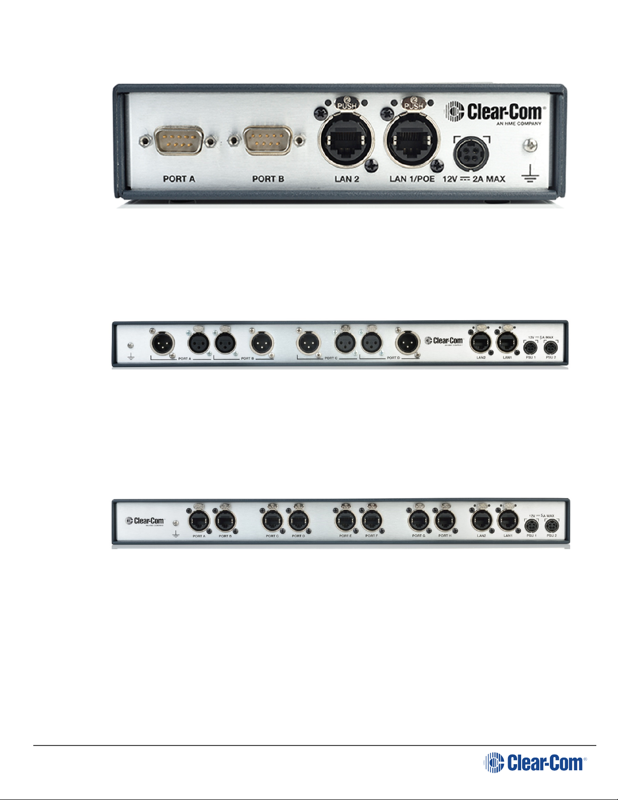
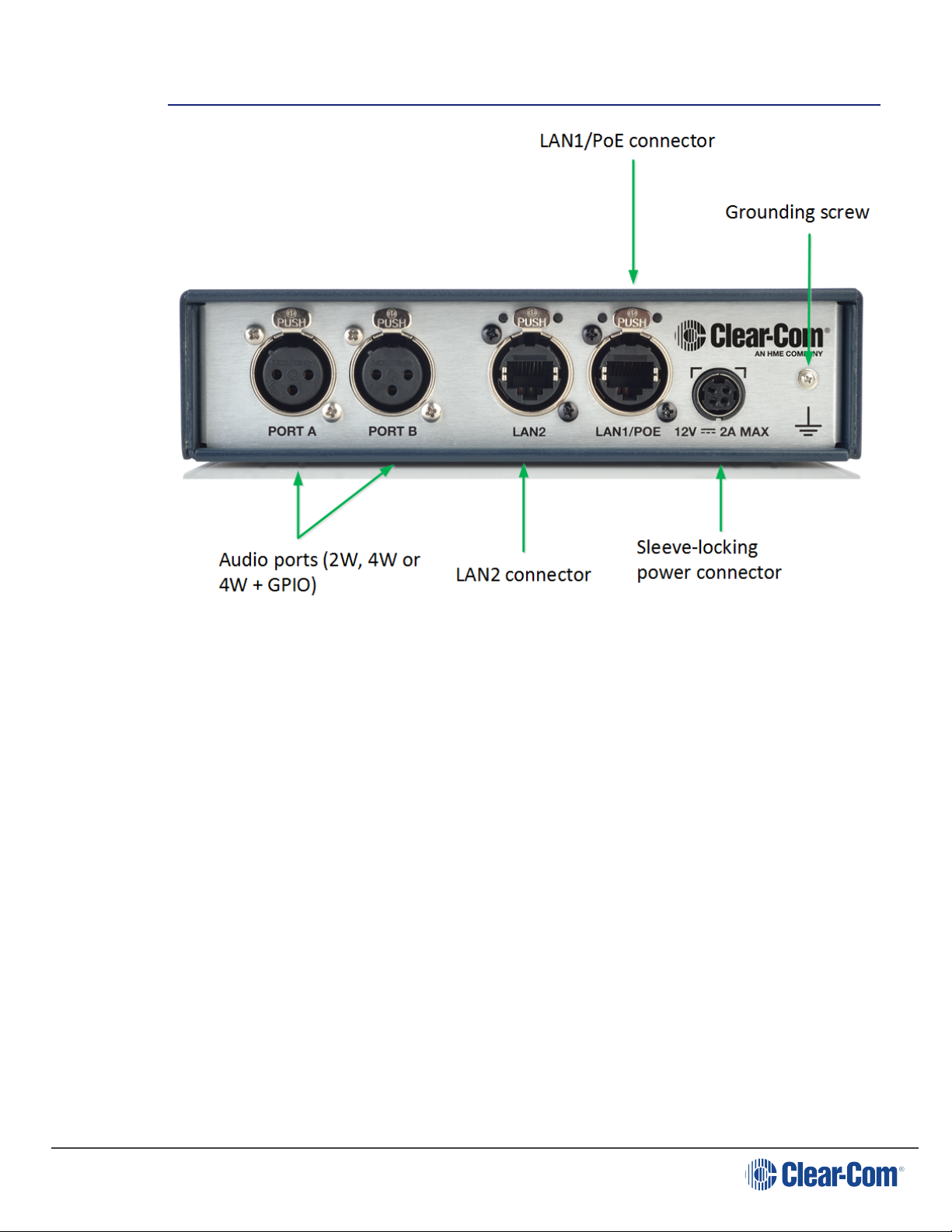
LQ is available in 8 models; the LQ-2W2, LQ-4W2 and LQ-4WG2 devices are small,
robust 2-port throw-down boxes for fast and convenient installation.
The LQ-R devices (LQ-R4W8, LQ-R2W4-4W4, LQR-2W4, LQ-R4WG8, LQR2W4+4WG4) are single rack units providing 4 or 8 ports in a combination of 4wire, 4-wire + GPIO and 2-wire options for more extensive installations.
User Guide| LQ Series 4.0
1.2
The LQ product line offers:
l HelixNet linking. HelixNet to IVC connectivity via an LQ unit allows HelixNet to
connect to a Clear-Com Eclipse matrix system.
l SIP connectivity. Up to 8 SIP clients can be connected to each LQ device.
l Agent-IC. Up to 8 Agent-IC clients can be connected to each LQ device.
l A mix of hardware and virtual ports of audio can be routed through the system
using customizable Virtual Partylines. LQ Series 4.0 offers a mix of physical
and 'virtual' ports.
l Each LQ-R unit allows up to 24 ports:
l 8 hardware ports
l 8 SIP ports
l 8 virtual ports. IVC ports and Agent-IC ports are considered 'virtual'
ports. Virtual ports can be used in any combination up to 8 in total.
l Up to six LQ units can be linked together providing a robust network for audio
over IP
Page 8
Page 9

l Browser- based Core Configuration Manager (CCM)
l Adjustable audio quality settings to make the best use of available network
resources
l Low latency OPUS codec
l LQ throw-down units: external power supply or Power over Ethernet (PoE)
l LQ 1-RU devices: dual redundant external power supply
l IVC-32 linking with Clear-Com Eclipse frames using G.722 codec (EHX 8.7 and
above).
1.3 2-wire features
l 2-wire throw-down units can be powered locally by PoE or external PSU
l 2-wire line termination
User Guide| LQ Series 4.0
l Auto nulling
l Clear-Com/RTS modes with both RMK/Call signaling pass-through (Clear-Com
only).
1.4 4-wire features
l Port Function switching alleviates the need for crossover cables
l Panel data pass-through facilitates the connection of Clear-Com panels to
matrix over any IP network
l Call signaling.
1.5 4-wire + GPIO features
l Network Control Events for flexible and scalable activation and passing of
GPIO and controls
Page 9
l Designed to work with low power 2-way radios (or any device that uses a
relay trigger)
l Passes GPIO/control/data between LQ and Eclipse Matrix frame.
Page 10
User Guide| LQ Series 4.0
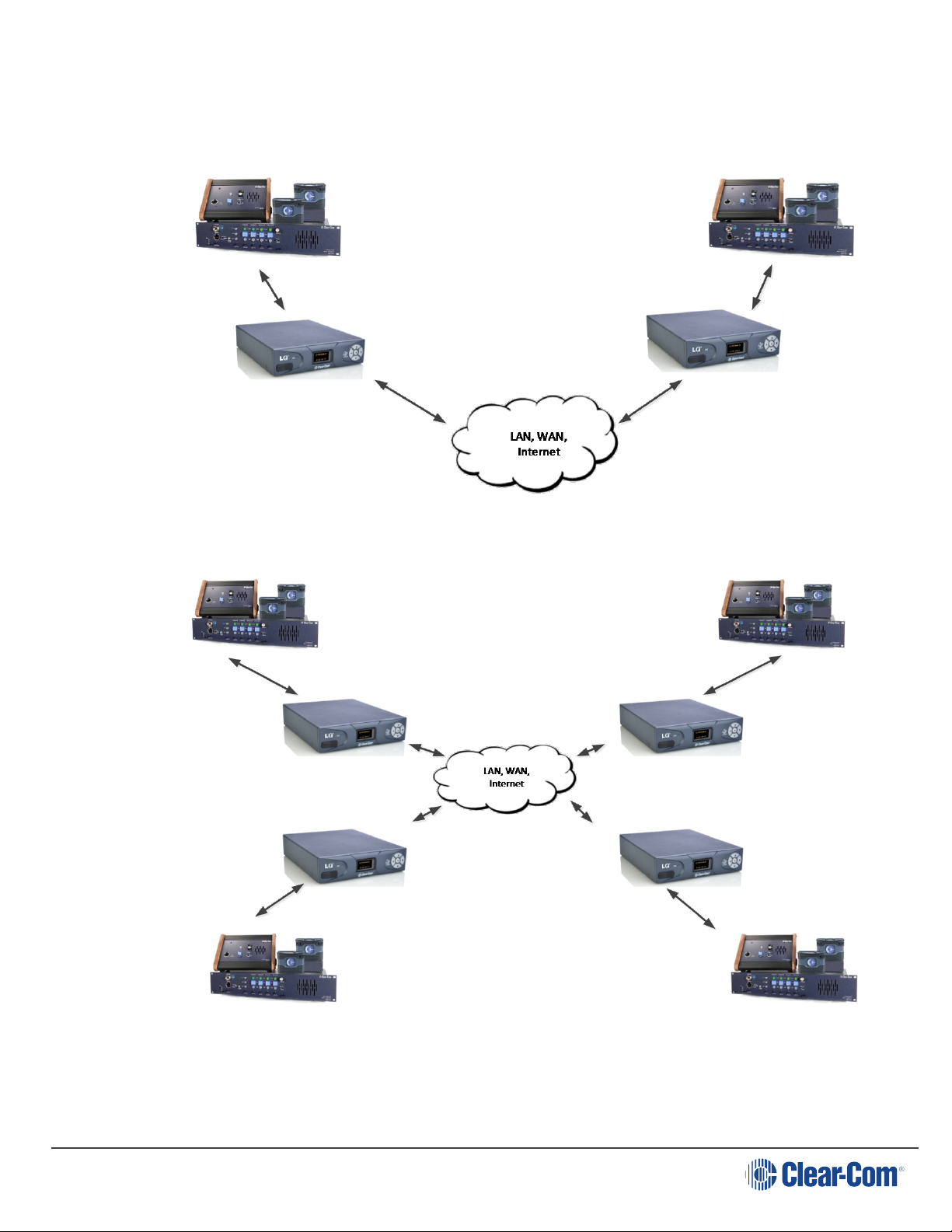
1.6 Example applications: 2-wire connections
1.6.1 Partyline to partyline (2-wire connection)
1.6.2 Partyline to partyline (2-wire connection) #2.
Page 10
Page 11
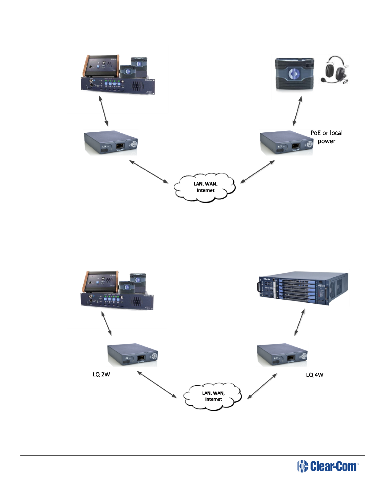
1.6.3 Partyline to beltpack
User Guide| LQ Series 4.0
1.7 Example applications: LQ to matrix connections
1.7.1 Partyline to matrix (2-wire to 4-wire)
Page 11
Page 12
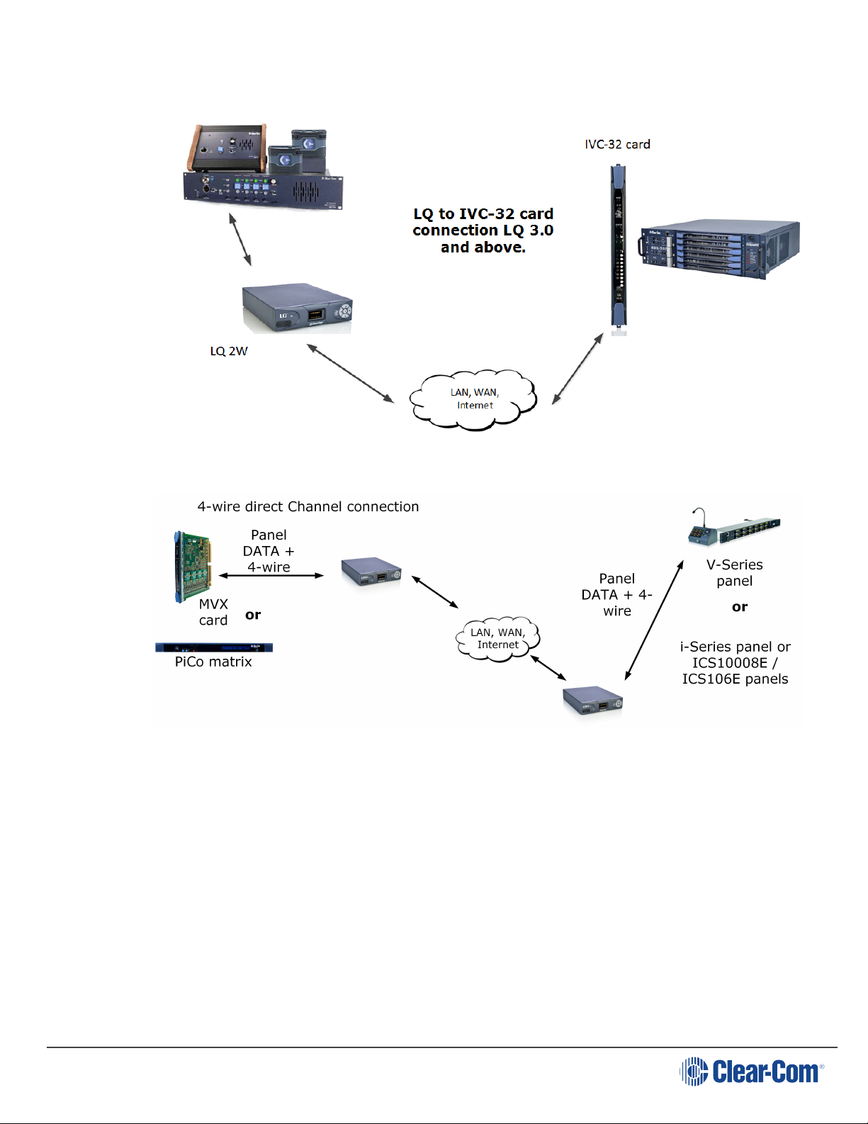
1.7.2 LQ 3.0 to matrix using an IVC-32 port.
User Guide| LQ Series 4.0
1.7.3 Remote panel to matrix connection
Page 12
Page 13
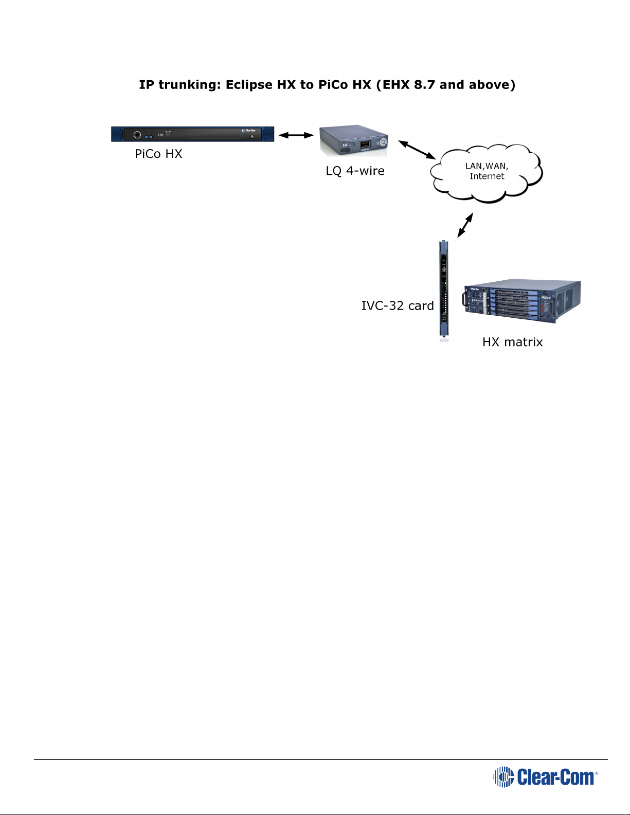
1.7.4 PiCo HX to Eclipse HX (8.7)
User Guide| LQ Series 4.0
Page 13
Page 14
User Guide| LQ Series 4.0
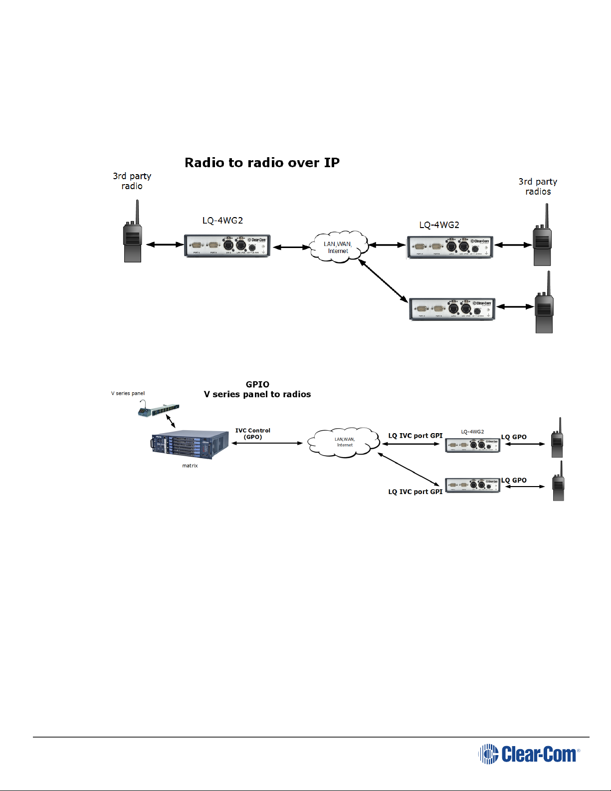
1.8 Example applications: Radio connections (GPIO)
GPIO signals are converted to digital signals and then passed across the IP
infrastructure (as with a 2-wire call signal).
1.8.1 Radio to radio
1.8.2 Panel to radio
Page 14
Page 15
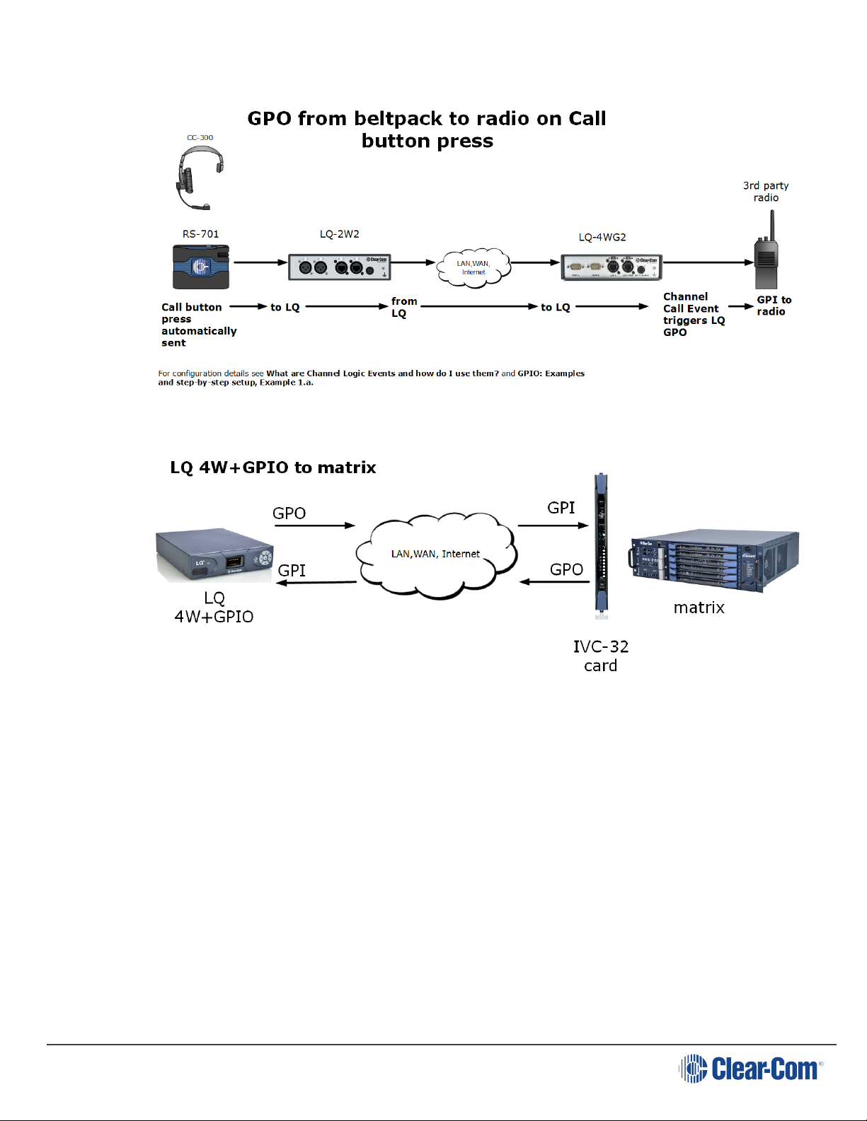
1.8.3 Call button to radio
1.8.4 LQ 4W+GPIO to and from matrix
User Guide| LQ Series 4.0
Page 15
Page 16
1.9 LQ and LQ-R series models
User Guide| LQ Series 4.0
1.9.1
1.9.2
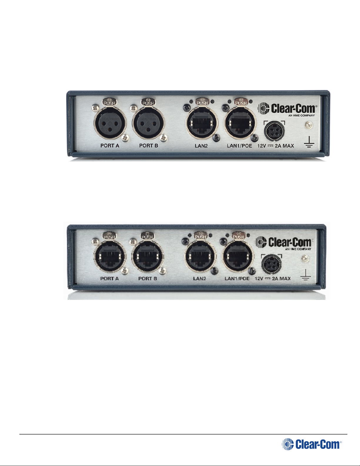
LQ-2W2 Throw-down unit
Two 2-wire Partyline connectors (XLR-3F)
LQ-4W2 Throw-down unit.
Page 16
Two 4-wire connectors (etherCON RJ45)
Page 17
User Guide| LQ Series 4.0
1.9.3
1.9.4
LQ-4WG2 Throw-down unit.
Two 4-wire +GPIO connectors (DB-9M)
LQ-R2W4 1 RU unit.
1.9.5
Four 2-wire loop-through ports. (XLR-3M/XLR-3F)
Dual redundant power supply connectors
LQ-R4W8 1 RU unit.
Eight 4-wire connectors, (etherCON RJ45)
Dual redundant power supply connectors
Page 17
Page 18
User Guide| LQ Series 4.0
1.9.6
1.9.7
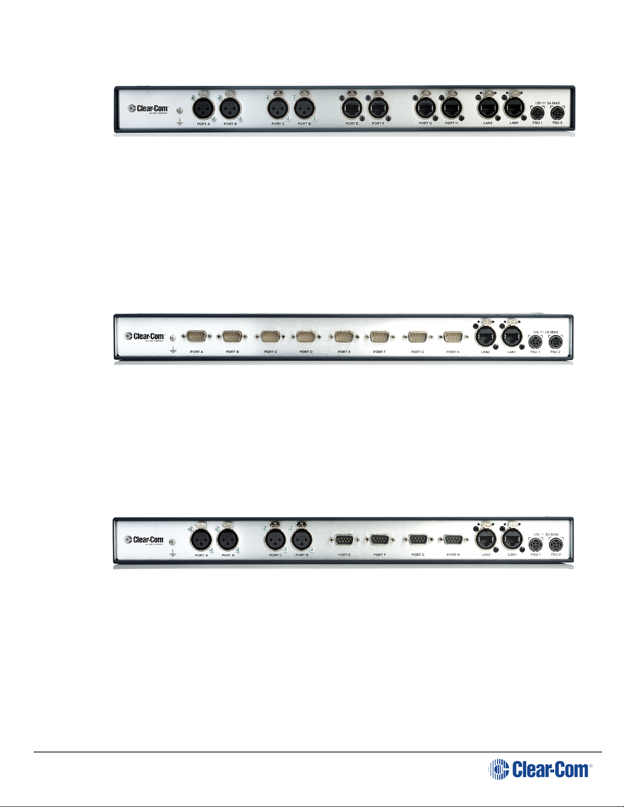
LQ-R2W4-4W41 RU unit.
Four 2-wire connectors (XLR-3F)
Four 4-wire connectors (etherCON RJ45)
Dual redundant power supply connectors
LQ-R4WG8 1 RU unit.
1.9.8
Eight 4-wire +GPIO connectors (DB-9M)
Dual redundant power supply connectors
LQ-R2W4+4WG4.
Four 2-wire connectors (XLR-3F)
Four 4-wire +GPIO connectors (DB-9M)
Dual redundant power supply connectors
Page 18
Page 19
2 Powering your LQ
User Guide| LQ Series 4.0
2.1
Note: When connecting the sleeve-locking power cable, be sure to push until the
Note: The 60 watt PSU can be used with the throw-down units if necessary.
Using the power supply unit (PSU)
l LQ units are supplied with a 24 watt sleeve-locking power connector.
l LQ-R 1RU units are supplied with two 60 watt sleeve-locking power
connectors. Use either power connector, or both to guard against one power
supply failing.
connector locks into the device.
Page 19
Page 20
User Guide| LQ Series 4.0
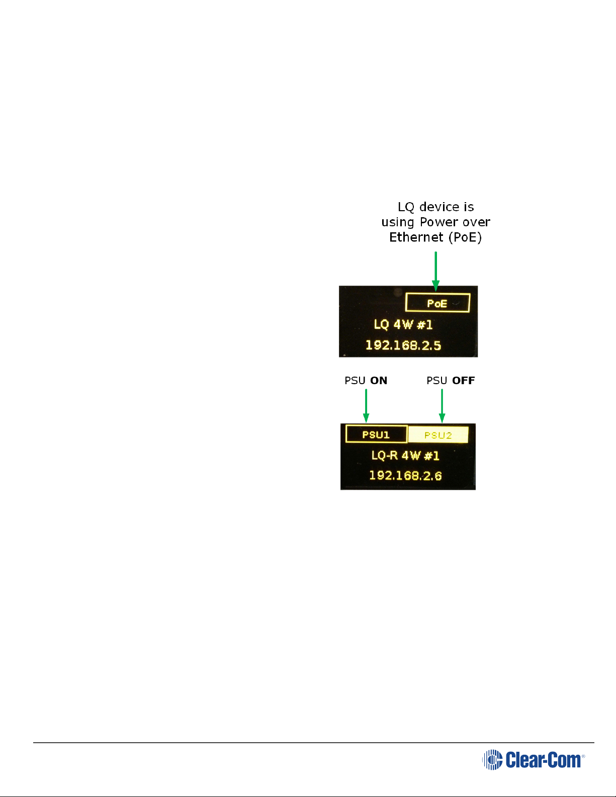
2.1.1
Understanding power display icons
You will be able to see the power status of your device from:
l The front panel of the unit
l The device icon in the web based configuration tool (the CCM).
These indicators will show if the unit is using PoE or the PSU (LQ throw-down units),
and which of the two power supplies (or both) are in use for the LQ-R units.
LQ throw-down units
If the device is using the PSU, this will be
lit up instead of the PoE indicator.
LQ-R 1 RU units
2.2 Using Power over Ethernet (PoE) with 2-port units
The 2-port units will receive power from the LAN1/PoE connector if required (this is
not the case for the larger LQ-R units).
When using PoE the LQ-2W2 supplies approximately 70 mA of power to drive the
wired beltpacks (about two beltpacks).
The units draw up to 12 watts of power (depending on what is connected to them),
so when using PoE you should have at least a Class 3 PoE switch.
If you exceed the power of your switch or network, the LQ device(s) will show a
persistent flashing green light, and not move beyond the Clear-Com splash screen.
Page 20
Page 21
User Guide| LQ Series 4.0
LQ series
unit
Power supply
Number of beltpacks powered by the
Partyline
LQ 24 watts 150 mA (~5 beltpacks) per device
LQ
PoE (device draws up to
12 watts)
70 mA (~2 beltpacks) per device
LQ-R 60 watts
250 mA (~10 beltpacks per pair of ports,
max 20 per device)
This indicates that the device is continually booting and needs more power.
Consider using the supplied sleeve-locking connector cable or a higher Class PoE
switch.
2.3 Power 2-wire beltpacks from the Partyline
2-wire beltpacks take power from the Partyline. The maximum numbers are shown
in the table below.
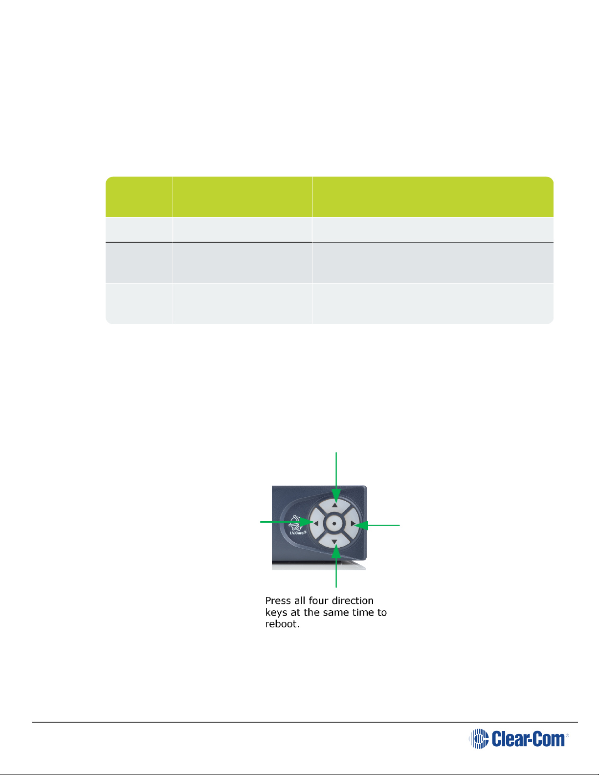
2.4 Reboot system
The system will start its boot sequence immediately when power is applied. If you
need to reboot for any reason, either cycle the power or press all four direction keys
on the control panel on the front of the LQ unit at the same time.
The system can also be rebooted using the front panel menu screens: Menu >
Administration > Reboot and from the CCM: Device > General >
Maintenance > Reboot.
Page 21
Page 22

User Guide| LQ Series 4.0
3 Core Configuration Manager (CCM) walkthrough
This section gives you an overview of your configuration tool. Find context sensitive
help in the user interface by clicking on the blue ? icon.
3.1 How to Access the Core Configuration Manager (CCM)
1. Make sure the LQ device is connected to a network (either LAN connector on
back of device).
2. Open a browser (PC, tablet, mobile) on the same network as the LQdevice and
input the IP address of your LQ in the addressfield. Find the IP address in the
front menu screens of your device.
3.1.1 Minimum requirements for the CCM
Supported on the latest versions of all major web browsers (i.e. Google Chrome,
Safari, Firefox, Internet Explorer, Opera).
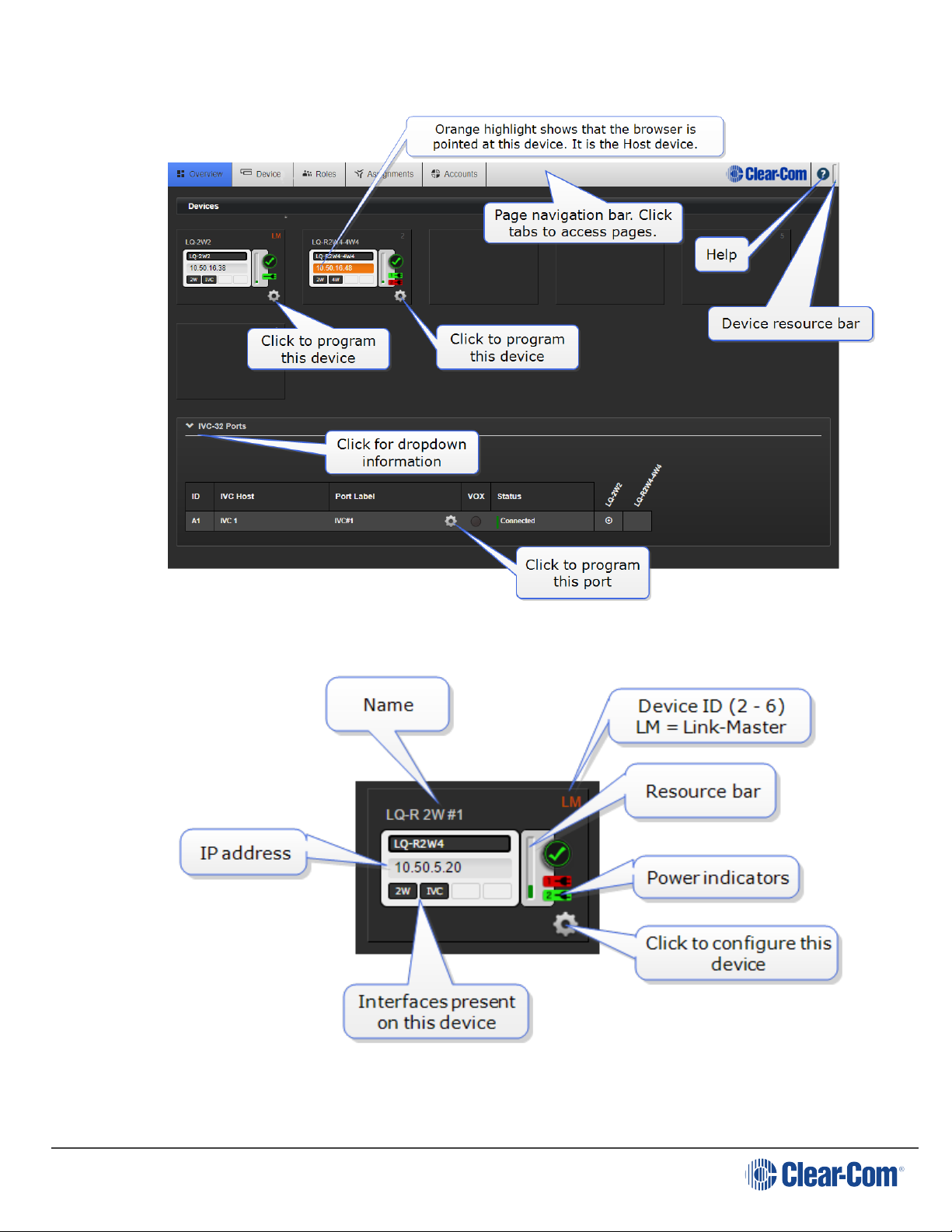
3.2 Overview
This page shows an overview of all the devices in your system. Devices in the upper
part of the page are the units in a Link-Group. As LQs are added to the group, they
appear in this screen. A HelixNet device can also be included in a Link-Group (LQ
4.0 and above).
On the lower part of the screen you can see the external systems that your LQ
device is connected to. These can be:
l IVC (matrix) connections
l SIP (telephony interface) connections
l Agent-IC (mobile client) connections.
If you have a HelixNet in your Link-Group, you will see the remote units that are
connected to the HelixNet Main Station in the lower half of the Overview screen.
Page 22
Page 23
User Guide| LQ Series 4.0
Page 23
Page 24
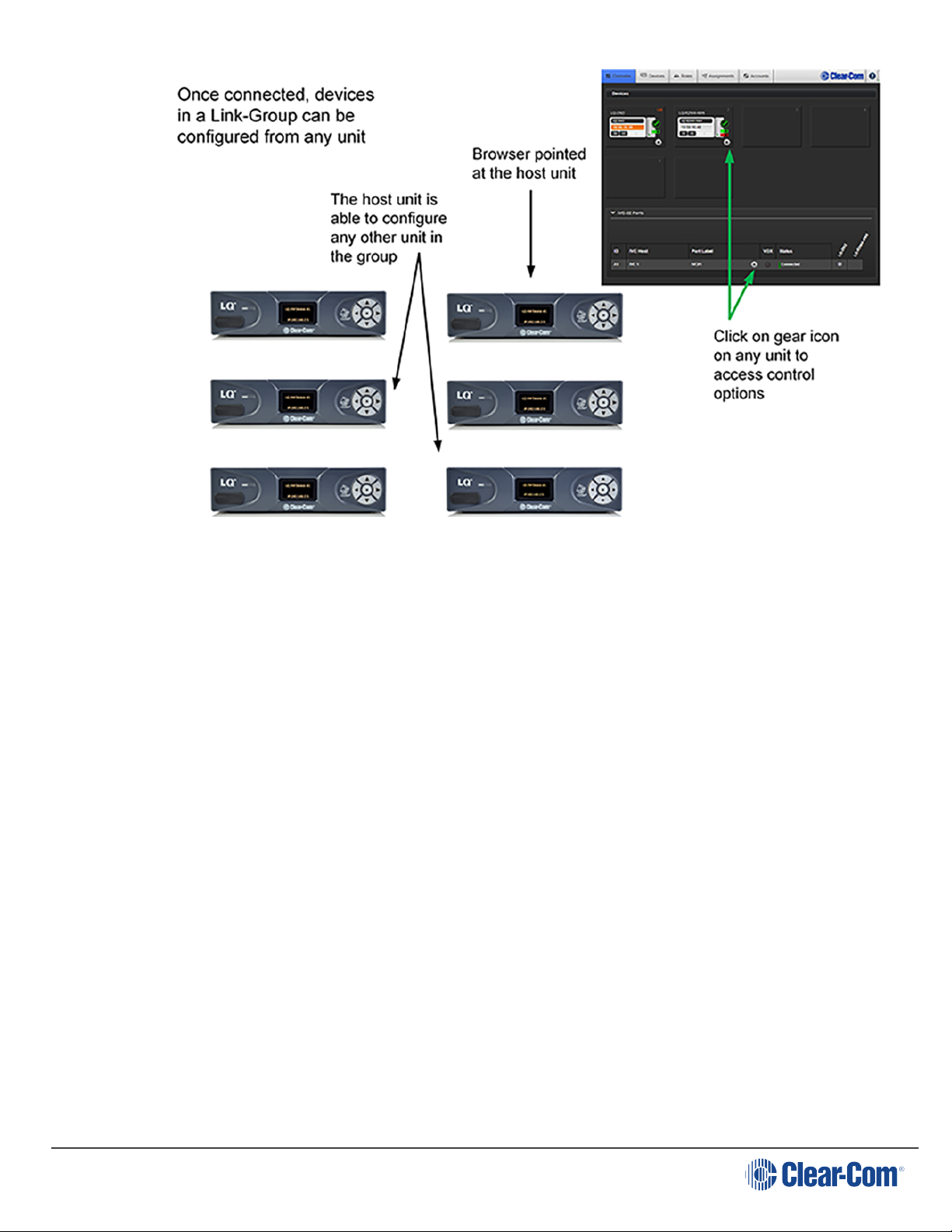
3.2.1 Device Configuration
Devices in a Link-Group can be configured either directly or by proxy, meaning that
the configuration operations for a unit are routed through the host device. The host
device is the unit which the browser is currently pointed to (orange highlight).
Click on the gear icon on any device.
You can use the Overview page to obtain diagnostic information for your all
systems. Whenever you see a > symbol, click to see a drop-down section.
Clicking the gear icon in any part of the CCM always takes you to programing
options.
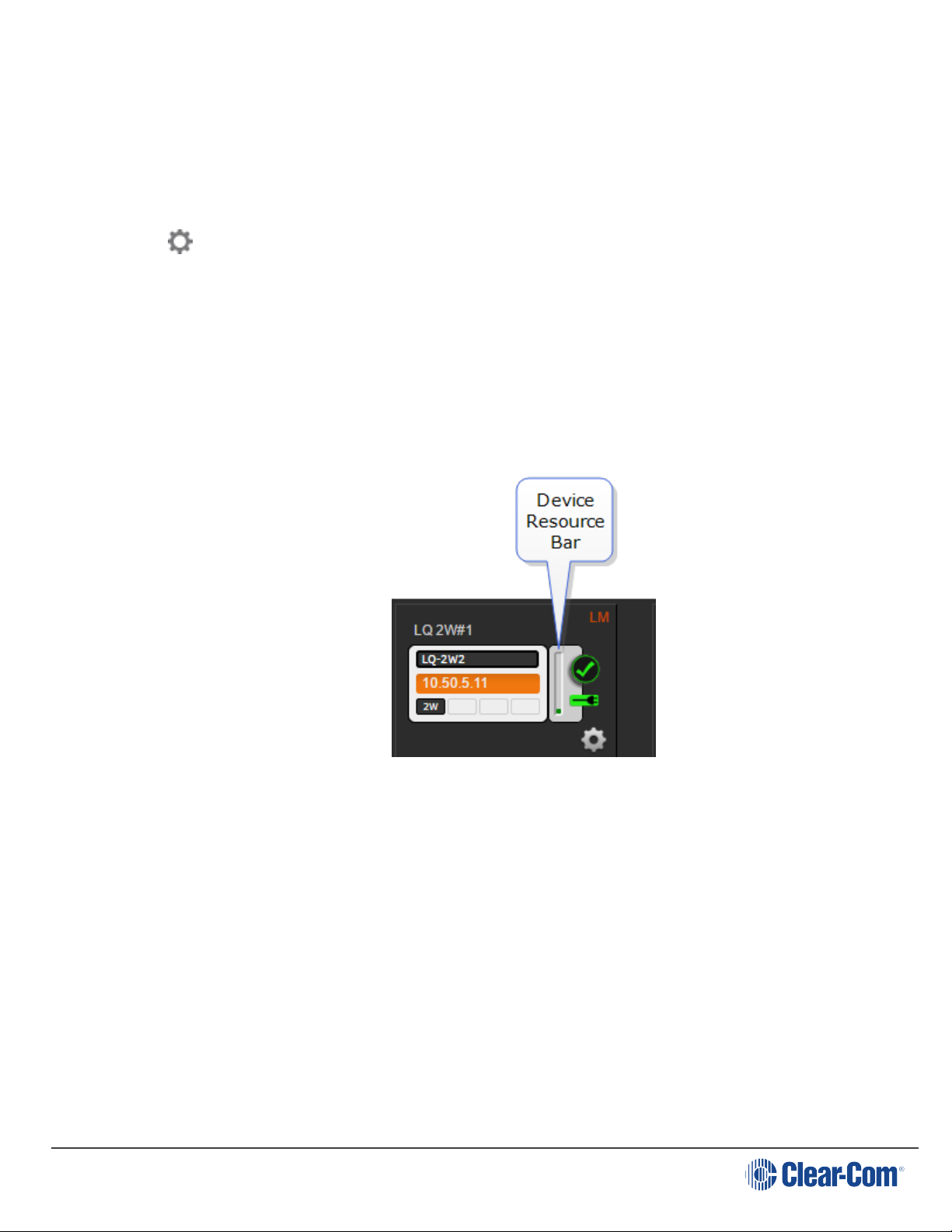
3.2.2 Resource Bar
User Guide| LQ Series 4.0
3.2.3
Page 24
About the Resource Bar
The Resource Bar is a tool that indicates the amount of processor power currently
allocated on that device.
l Bar orange = 70% of processing power reached
l Bar red = 80% of processing power reached
The device will work in the red zone, but the reliability of the audio response may
decrease.
Page 25
User Guide| LQ Series 4.0
The CCM will start limiting demands on the unit (for example it will prevent a port
being added to a Channel, or the addition of an IVC-32 or multi-Channel port) in
order to maintain good audio quality and responsiveness.
3.2.4
To optimize resource usage
l Reduce the network quality in the local audio mixes. Higher network quality
takes more resource.
l Reduce the number of ports that are in different Channels. Several ports in the
same Channel do not take much resource. It is more demanding if the ports
are spread over several Channels.
l Using a LAN/WAN/Routed Network Optimization mode will reduce the
overall resource usage (set Link-Group Optimization mode in the Linking
page of the CCM).
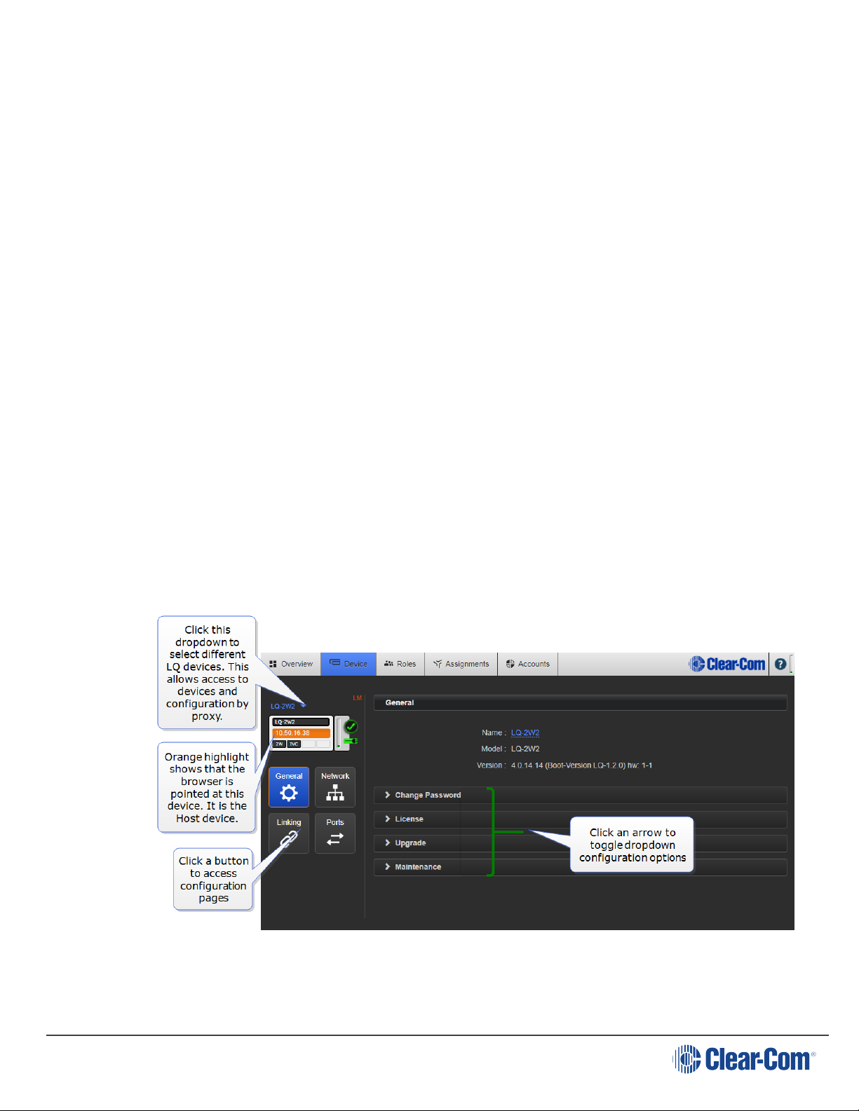
3.3 Device
The Device page takes you to the configuration options local to your LQ device. On
the left you see configuration page buttons; General, Network, Linking and
Ports. Switch between devices in a Link-Group using the dropdown menu just
above the device icon.
Page 25
Page 26
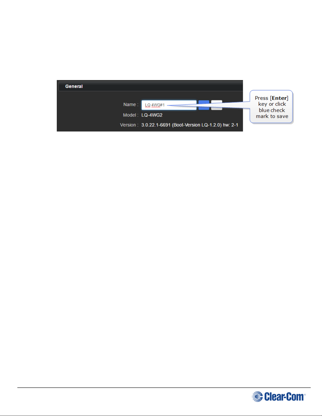
3.3.1 General Settings
Configuration options local to your LQ Series 4.0 device. Click a heading to expand
drop-down.
User Guide| LQ Series 4.0
3.3.2
3.3.3
3.3.4
Re-name your LQ.
Change Password
Change the password to the Core Configuration Manager local to that device. You
can only change the password from the Host device, not by proxy.
License
Click here to activate licenses for SIP or Agent-IC clients.
For more information, see:
Licensing on page 138
3.3.5
Note: All devices in a Link-Group MUST be running the same version of the software; you
Upgrade
Click Select File and navigate to where you have stored the upgrade file (.gz
extension). Then click Upgrade when the Upgrade button turns blue. Wait while
the device reboots itself.
An LQ unit must be upgraded from the host device (the device that the browser is
currently addressing). The units cannot be upgraded by proxy.
To access a device directly as a host you must input that unit's IP address into a
browser to access the CCM. The host device always has an orange highlight.
must upgrade all devices in the group.
After upgrades you are advised to check linking connections and auto null partyline
ports.
Page 26
Page 27

User Guide| LQ Series 4.0
3.3.6
Maintenance
Reset the unit to default settings.
Reboot the system.
Create a support archive. Support Info provides a 'snapshot' of the device's
operational information for troubleshooting purposes.
3.4 Network
Dynamic host control protocol (DHCP) or Static IP address allocation?
Default setting: DHCP
It is recommended that the Link-Master in a Link-Group has a static IP
address.
Most networks use DHCP to allocate IP addresses. Because of this, DHCP is
recommended for fast set-up as the devices can be immediately connected to any
network that provides DHCP. The addresses provided are dynamic and may change
from time to time. Because DHCP IP addresses can change, the Link-Master should
have a static IP address, or it may lose connectivity to the group.
For more information, see:
Network settings (IP) on page 74
Internet connectivity on page 78
Link-local environments on page 76
External IP address and External Port setting
For efficient networking, these details should be set for any LQ device that connects
over a firewall.
Note: The Link-Master uses TCP port 80 for management, and TCP/UDP port 655 for
audio. See Linking over Internet or WAN below for port addressing and port
forwarding details.
For more information, see:
Linking over Internet or WAN on page 60
Internet connectivity on page 78
See your network administrator if you require network details.
Page 27
Page 28
3.5 Linking
In this page you can program a Link-Group. A Link-Group is a method for
connecting LQ devices over LAN, WAN or internet so they share audio and data
between them.
A Link-Group can contain both LQ devices and HelixNet Main Stations (LQ 4.0 and
above).
User Guide| LQ Series 4.0
Devices can be seen and programmed from any device in the group.
Page 28
Page 29
User Guide| LQ Series 4.0
Page 29
Page 30
User Guide| LQ Series 4.0
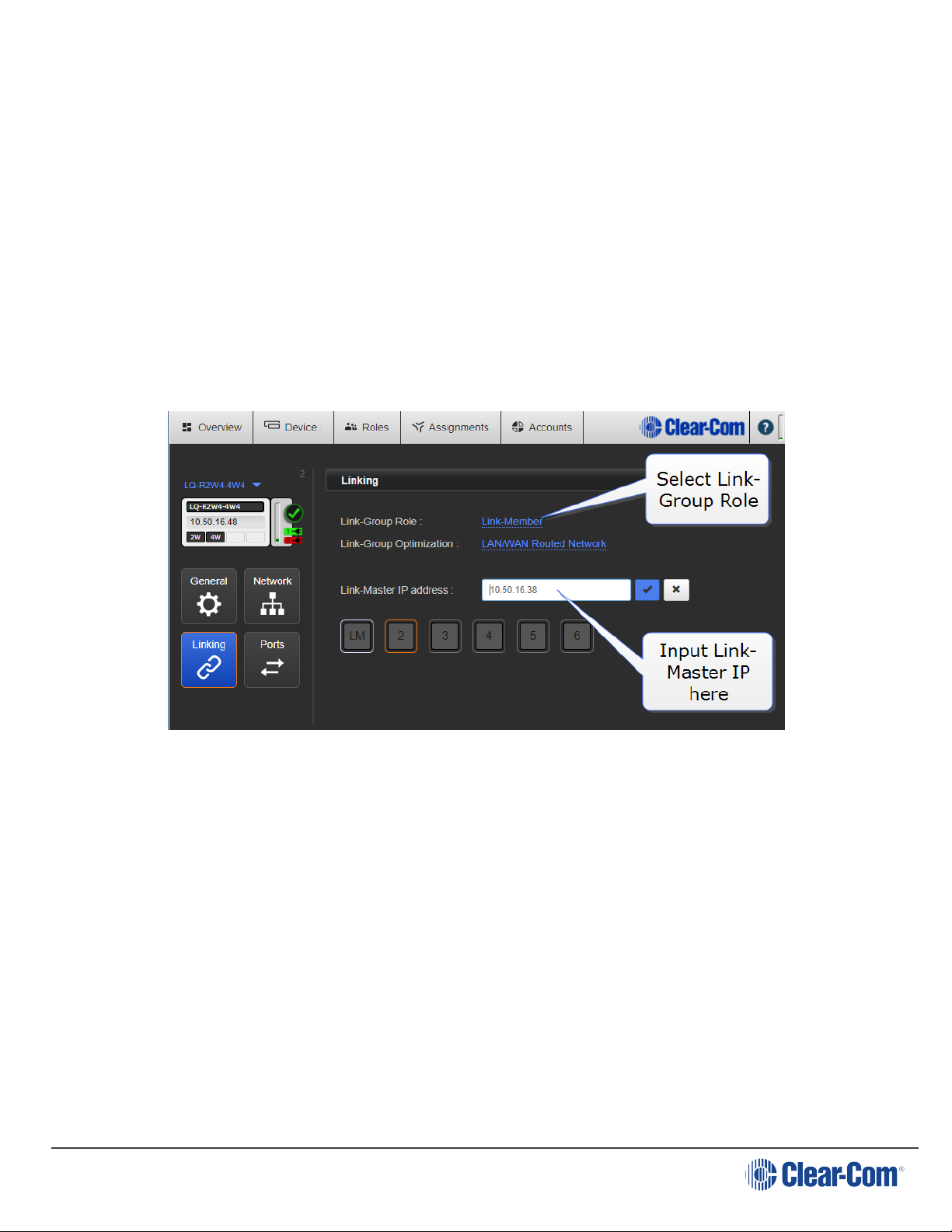
3.5.1
Note: If linking with a HelixNet Main Station, the HelixNet device must always be
Link-Group Role
The Link-Master is responsible for synchronization and distribution of audio,
Channel names and device availability throughout the Link-Group. Each group
needs a Link-Master.
To create a group you must connect LQ member(s) to a Link-Master. Change this
setting to Link-Member on the device to be connected to the master. When you
change the role to Link-Member, you can then enter the Link-Master IP address
here to link the devices. Find the device IP in the front menu screen of the device.
designated the Link-Master.
3.5.2
Page 30
To take an LQ device out of a Link-Group, change it's role back to Link-Master here.
This will disconnect the device from the group.
Related Links
About Linking on page 58
Creating a Link-Group on page 48
Link-Group Optimization
Internet/NATed network (Default mode)
Use this setting whenever the network you are using crosses firewalls. This is the
default mode and will work with all networks. However, it requires more processing
power of the LQ device and may affect latency.
Page 31

User Guide| LQ Series 4.0
LAN/WAN network
Use this mode when using LQ in a private network. It uses less network and CPU
resources and gives better latency than the default.
3.5.3
Link-Master IP
Enter the Link-Master IP address to link a device to a group. You only see this field
when the device is set to Link-Member.
See Creating a Link-Group on page 48 for step by step details.
If connecting over firewalls, this will be the Link-Master's external (public) IP
address and the port mapped to TCP port 80 at the firewall.
See Linking over Internet or WAN on page 60 for port forwarding details.
Related links
Internet connectivity on page 78
3.6 Ports
Settings vary according to port type.
LQ 4.0 and above allows five different port types: 2-wire, 4-wire, GPIO, IVC and
SIP. You will see the port types available to your system in this page. Use the Port
Selector to select ports for programing. Use the drop-down device selector for
moving between different devices in a Link-Group.
In this page you can set port variables such as input gain (volume) and VOX
detection. You can name the port here. More than one port can be selected for
configuration at one time.
You can also program the GPIO triggers for your system, allowing relays to be sent
to radios or other remote and third party equipment.
In LQ 3.0 and above, it is possible to put ports in more than one Channel.
VOX settings are available on all LQ port types.
Page 31
Page 32

User Guide| LQ Series 4.0
Page 32
Page 33

User Guide| LQ Series 4.0
3.6.1
2-Wire specific settings
Autonull: You must perform auto-null when any change in the connected 2-wire
equipment occurs or there is a significant temperature change.
Termination:Termination is enabled automatically when power is enabled on a 2wire partyline. Termination should only be enabled on one device within a 2-wire
circuit. Termination can be toggled off and on in the configuration user interface.
For more information, see:
Power 2-wire beltpacks from the Partyline on page 21
Page 33
Page 34

User Guide| LQ Series 4.0
3.6.2
4-Wire specific settings
Page 34
Page 35

User Guide| LQ Series 4.0
3.6.3
4-Wire + GPIO specific settings
Note: A 4-wire+GPIO port will not transmit call signals in the form of data. The GPO
Output Trigger must be set to Channel Call Event, or a signal will not be sent.
3.6.4
IVC-32
You only see IVC32 ports in this screen if they have been previously created in the
Accounts page.
Page 35
Page 36

User Guide| LQ Series 4.0
3.6.5
SIP specific settings
You only see SIP ports if they have been previously created in the Accounts page.
Page 36
Page 37

User Guide| LQ Series 4.0
For more information, see:
What are Networked Control Events and how do I use them? on page 83
Multi-Channel Ports on page 37
VOX (audio-gating) on page 73
3.6.6 Multi-Channel Ports
It is possible to assign one port to many Channels. There is no limit on the amount
of Channels a port can be put into, but the rules for device resource usage apply.
When the unit is reaching the limits of its capacity, the user interface will stop you
from assigning more ports.
When do I use multi-Channel ports?
An example of when to use multi-Channel ports might be if you have a program
feed or stage announce that should be heard by several teams or groups.
Page 37
Page 38

User Guide| LQ Series 4.0
3.6.7
Enable multi-Channel port feature
Once enabled, multi-Channel ports are available in the Assignments page, ready to
be assigned to more than one Channel.
Note: If the port has already been put into a Channel, it will be unassigned from the
Channel when you enable multi-Channel support.
Page 38
Page 39

User Guide| LQ Series 4.0
For more information on how to put ports in Channels see Assignments on page
40.
Note: Multi-Channel ports will not be placed in a local audio mix, they will be transported
as a single audio stream. You can use the Resource Meter as a guideline for device
capacity.
For more information, see:
Resource Bar on page 24
3.7 Roles
When using LQ, some of the products you interconnect with use Roles for the
purpose of intercom setup. Roles are preset configurations, used to simplify and
control your intercom installation. You can work with default Roles which can be
cloned or edited. You can also create your own Roles if required.
The products that use Roles when connecting to LQ devices are: HelixNet and
Agent-IC.
When a HelixNet device is linked to LQ in a Link-Group set up, the Role
configuration from the Master HelixNet device will override the LQ units.
For more information about HelixNet Role configuration, see the HelixNet User
Guide, available from the Clear-Com website.
For more information about Agent-IC Role configuration see Agent-IC and LQ on
page 131
Page 39
Page 40

User Guide| LQ Series 4.0
3.8 Assignments
Network transmission controls/transport settings are in this page (LQ only).
This is where you will assign ports to Channels. All devices, with their associated
ports appear in the left margin of this page.
In the center are three tabs; chose from All, Channels and Directs.
Channels (up to 24 in total per Link-Group) are shown on the right.
To route audio:
1. Choose Channel type; Channel or Direct.
2. Click on an available Channel to select it or click '+' to create a new one.
3. With the Channel selected (orange highlight), click '+' next to the port you
require to put into the Channel.
4. Repeat step 3 as often as required.
Page 40
Page 41

User Guide| LQ Series 4.0
Note: Network transmission controls are in this page.
3.8.1
Note: Direct Channels are not available in a HelixNet system.
3.8.2
Channel or 4W Direct Channel?
An LQ Channel is made up of multiple audio sources which operate as a partyline.
All sources in a Channel can hear and talk to each other. A 4-wire direct (panel)
Channel, by contrast, is a connection between two ports only. A 4-wire direct
(panel) connection cannot be included in a Channel and is configured separately.
Local Audio Mix (LAM)
Each LQ device within a Channel performs its own local audio mix (submix). The
LAM mixes audio at a very early stage of the audio transport which reduces the
latency of the audio streams (below 4ms) and improves audio processing. LAM is a
Page 41
Page 42

User Guide| LQ Series 4.0
way of improving latency, increasing the capacity of an LQ device in certain user
cases and reducing network usage.
The LAM is performed automatically when ports are added to a Channel.
Note: The ports from each LQ appear within a box, with the local audio mix icon in the
bottom right corner, where you can program network settings.
Network settings within a Channel are set on a per-device basis. To set differing
network quality for ports from the same device, put the ports in separate Channels.
Note: LAM is not available if you are using a HelixNet/LQ Link-Group.
3.8.3
3.8.4
Page 42
Local Audio Mix/transport settings
Click/touch a blue label in the CCM to access settings.
Silence suppression. Default = Disabled
Enabling this option will stop transmission and implement comfort noise when
silence is detected. This is done to conserve network resources.
Recommended network settings
l Internet - very low or low
Page 43

User Guide| LQ Series 4.0
Network Quality. Click on the slider to
set.
Default setting shown in Bold
Transmit
Audio bitrate 16, 32, 48, 64, 128 Kbps
Audio bandwidth 12, 20 kHz
Packet size 60, 40, 20, 10, 5 ms
Receive
Jitter (min-max)
60-200, 40-100, 20-60, 5-60, 3-60
ms
Unit latency
80-220, 60-120, 40-80, 25-80, 23-
80 ms
l LAN/WAN - balanced or high
l LAN only - very high. This option enables 20 kHz bandwidth.
3.8.5
Custom setting
The Custom option allows adjustment of the jitter buffer setting independent of bit
rate and packet size.
The jitter buffer setting is designed to buffer audio received to prevent loss if there
is network jitter. Note that the jitter buffer selection will directly affect the latency.
This is because the lower number in the jitter range represents the amount the LQ
unit will buffer audio before delivering it to the port. A bigger jitter buffer setting will
increase latency in milliseconds.
Note: The network setting is the bandwidth from the LQ device into the IP network.
Note: Within the Custom setting, selecting an Audio Bitrate of 128 Kbps will automatically
set Bandwidth to 20 kHz,
3.9 Accounts
In this page you will generate and maintain accounts to external systems.
l Agent-IC client accounts
l PBX (SIP) accounts
Page 43
Page 44

l IVC (matrix) accounts
User Guide| LQ Series 4.0
User log in credentials (User ID and Password) are stored in this page for each
account.
Agent-IC and telephony (SIP) accounts need a license (see your Clear-Com
representative for information).
For more information, see:
Program Agent-IC to LQ connectivity on page 135
Program LQ-SIP standalone on page 101
Clear-Com Eclipse matrix connections on page 79
Licensing on page 138
Page 44
Page 45

User Guide| LQ Series 4.0
4 Basic set up (LAN)
4.1 Setting up your LQ environment within a LAN
Gather the following equipment:
l 2 x LQ units (LQ #1 and LQ #2)
l 2 x provided Power Supply Units (PSUs)
l 2 x Straight-through RJ45 Ethernet cables
l 1 x Network connection with Dynamic Host Control Protocol (DHCP) server
present (preferred method)
l 2 x 2-wire, 4-wire and/or GPIO equipment to provide an audio connection to
each LQ
l 2 x 2 Network connections available for connecting each LQ to your network.
1. Connect either LAN port of LQ #1 to the local network equipment.
2. Connect either LAN port of LQ #2 to the local network equipment.
3. Connect the provided PSU to each LQ device. Once booted, each device will
display an IP address on the front panel display.
Page 45
Page 46

User Guide| LQ Series 4.0
4. Once the devices are operational, you will program each device through the
browser-based Core Configuration Manager (CCM).
5. Access the CCM. From a device connected to your network, open a Web
browser. Enter the IP address as displayed on LQ #2 device in the address field
of the Web browser (Chrome, Safari, Firefox, IE, Opera). This takes you to the
CCM.
6. Default username and password for the CCM: admin, admin.
Page 46
Page 47

User Guide| LQ Series 4.0
Note: The IP address will be allocated by DHCP (default mode). In the event that the
network does not serve DHCP or there is no network connection, the IP address will
revert to a link-local address. If necessary IP addresses for the devices can be
configured in the Network page of the CCM. See information links at the bottom of
this page if you require more information.
7. Connect the audio equipment to Port A of each LQ device.
8. Once the LQ devices are set up, proceed to Creating a Link-Group on page
48.
Page 47
Page 48

User Guide| LQ Series 4.0
For more information see:
Static IP configuration on page 74
4.2 Creating a Link-Group
Before linking units together, one LQ device must first be designated as the LinkMaster by setting that device's role to Link-Master. Every other LQ device within
the Link-Group will then be set into a Link-Member role which allows the linking of
those units directly to the Link-Master.
When creating a HelixNet/LQ Link-Group the HelixNet must always be designated
the Link-Master.
Page 48
Page 49

User Guide| LQ Series 4.0
In this example, LQ #1 will be left as Link-Master (default configuration) and LQ #2
will be linked to it.
4.2.1
How to create a Link-Group
1. Navigate to Device > Linking on the CCM of LQ #2.
2. Click Change Role to Link-Member.
3. Within the Master IP address field, enter the IP address as displayed on the LQ
#1 device. Click on blue check mark or press <ENTER> key to submit.
4. The next available Device ID will be selected by default (highlighted in blue) but
can also be manually selected.
Page 49
Page 50

User Guide| LQ Series 4.0
5. Click Apply changes.
LQ #1 and LQ #2 will now be linked (operation may take up to 30 seconds to
complete). If there is existing configuration on the member LQ, this will be
replaced by the configuration of the master.
6. Navigate to the Overview page (top navigation bar). Both LQ devices should be
displayed on this page.
7. Before continuing, if either LQ device is a LQ-2W2 model, you may need to
auto-null both ports (power must be present on the 2W circuit before auto-null
is possible). For each device to be auto-nulled, navigate to Device > Ports.
Page 50
Page 51

User Guide| LQ Series 4.0
8. Expand port sections and click on the Auto-Nulling button for each port.
Note: The auto-nulling operation emits a loud hiss on the circuit. When auto-nulling,
ensure that all talk buttons on external Partyline devices are turned off.
For more information, see:
About Linking on page 58
In LQ 4.0 and above a HelixNet Main Station can also be included in a Link-Group.
LQ to HelixNet connectivity on page 123
4.3 Using Channels to route audio
1. Click on the Assignments button within the navigation bar.
2. Select the Channels tab.
3. Select Channel 1 (or other Channel) from list on the right of Assignments page.
4. Add Port on each device to required Channel by clicking on the + symbol to the
right of each port.
Page 51
Page 52

User Guide| LQ Series 4.0
You should now be able to pass audio and call/RMK signaling to/from Port A on each
device.
Channel 1 must be selected before audio can be assigned to it. This is shown by an
orange highlight.
Page 52
Page 53

5 Front panel interface
From the front panel of the LQ you can:
l Set audio configuration
l input gain
l output gain
l Set VOX configuration
l VOX
l Threshold
l Delay
User Guide| LQ Series 4.0
l Set 2-wire specific settings
l Powering of the line
l Clear-Com/RTS mode
l Auto-nulling
l Termination
l Set 4-wire specific settings
l Port Function: set port function of Ethernet cable ‘to Matrix’ or ‘to Panel’,
l Vox levels
l Baud rate
l See GPIO settings
Page 53
l Test GPO hardware trigger
l Set Mic level/line level (mic level for use when connecting directly to a radio)
l Set device settings
Page 54

User Guide| LQ Series 4.0
l Brightness of OLED
l Screensaver time-out
l Reboot
l Reset-to-default
l Networking
l Edit network details
l Hang up SIP calls
5.1 How to access front panel menu options.
5.2 Programming network details from LQ device front screen
In LQ version 3.0 and above network details can be input and changed from the
device front screen menu, as well as from the CCM.
Note: You can also test that the device GPOs are firing correctly from the front screen
menus. Navigate to Menu/ports/port and scroll down.
Page 54
Page 55

User Guide| LQ Series 4.0
5.2.1
How to edit network details from the device menus
1. Navigate to Menu > Networking > Edit. Edit is at the bottom of the
networking list. Use the arrow keys to navigate menus.
2. Disable the DHCP setting on your device. This allows you to access network
details.
Disable DHCP and select IP for editing.
Page 55
Page 56

Edit and save IP address.
User Guide| LQ Series 4.0
Page 56
3. Repeat for Subnet mask, Gateway, and DNS as required.
Page 57

6 Linking
6.1 What is a Link-Group?
A Link-Group is a set of LQ devices connected over IP so they share audio and data
between them.
With LQ 4.0 and above a HelixNet device can also be included in a Link-Group. This
increases the available ports and the range of a HelixNet system.
User Guide| LQ Series 4.0
Page 57
Page 58

User Guide| LQ Series 4.0
The Core Configuration Manager (CCM) for any LQ host can be accessed by entering
the IP address as displayed on the front panel display of the LQ host into a web
browser's address field. All devices in the Link-Group can be viewed and configured
through any single host in the Link-Group.
Note: A HelixNet Main Station can also be linked in a Link-Group formation. The basic
principles are the same for a HelixNet/LQ Link-Group, though there are a few
differences in operation.
For more information, see:
LQ to HelixNet connectivity on page 123
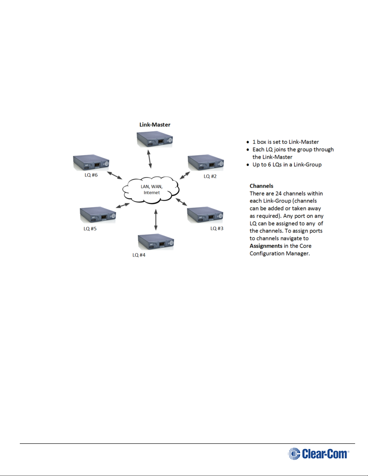
6.2 About Linking
A Link-Group:
l Can contain up to 6 LQ devices or up to 6 of a combination of HelixNet Main
Stations and LQ devices
l Must have one unit designated as Link-Master
Page 58
l Performs a “best effort” approach to creating a mesh network between all the
devices within the group.
Page 59

User Guide| LQ Series 4.0
6.3
Note: The Link-Master must be reachable on TCP port 80 and TCP/UDP port 655 by all
Note: It is recommended that the IP address of the Link-Master is allocated statically.
Note: Any device can be set to Link-Master mode. Link-Master mode is the factory default
The Link-Master role
The Link-Master role serves three main purposes:
1. It facilitates Link-Group membership.
2. It is the owner of Channel names, meaning that Channel names will only persist
(be maintained consistently) if the Link-Master is operational.
3. It is responsible for the synchronization and distribution of both configuration
and device availability status throughout the Link-Group.
devices within the Link-Group.
When allocated by DHCP the IP address can change. If this happens the LQ devices
will no longer be able to reach the Link-Master device.
setting.
Page 59
Page 60

6.4 The Link-Member role
LQ devices that are not designated master will have the role of Link-Member.
Joining a device to a Link-Group requires that device to be set to Link-Member role
which will prompt the user to enter the address of the Link-Master.
If a Link-Member device loses connection to its Link-Master, the front panel LED of
that device will turn red until the connection is restored.
6.4.1 Linking units
The only way to join devices to a Link-Group is through the Linking page of the CCM.
Only the IP address of the Link-Master is required during this set up.
6.4.2 LQ restricted IP range
LQ units use the IP range 172.23.xx.xx for linking. Because of this, this IP range
should not be used for any devices (including LQs) when working with the LQ Series
system. Clear-Com cannot guarantee reliable behavior if this address range is
used.
User Guide| LQ Series 4.0
6.4.3 Linking over a LAN
This is the simplest way to link devices together. This type of environment enables
the highest potential level of communication quality and the best availability of
resources. When linking over a LAN, set Link-Group Optimization to LAN/WAN
routed network in the Linking page of the Core Configuration Manager (CCM) for
best latency performance and use of resources.
6.4.4 Linking over Internet or WAN
When linking over the public Internet, addressing of the Link-Master becomes more
complicated as the Link-Master must be made externally reachable to all LinkMembers. This is achieved by creating port forwarding rules within the firewall.
Note: A HelixNet/LQ Link-Group does not operate over the Internet. This is because the
codec that HelixNet uses (WavPack) is not optimised for the Internet. Internet
connectivity when using HelixNet and LQ is achieved using a tie line.
Page 60
Page 61

6.5 How to link LQ units over a firewall
User Guide| LQ Series 4.0
The Link-Master uses TCP port 80 for management and TCP/UDP port 655 for audio.
You will need to create port-forwarding rules within your firewall to make these
ports externally accessible to the Link-Master device.
When creating a Link-Group over the public internet, Link-Members need to be
given the Link-Master’s externally reachable IP address and the port that is
forwarded to port 80. This information is entered in the Linking page of the CCM.
Note: If no port forwarding rules have been applied the LQ devices will find the correct
default ports automatically, so there is no need to specify a port.
Once the devices are linked in a group, they will share network details with each
other automatically. To facilitate this, the network details, including the port that is
forwarded to TCP/UDP port 655 need to be configured in the Link-Master’s
Network page. If no port forwarding rules have been applied, it is not necessary to
specify a port.
Page 61
Page 62

User Guide| LQ Series 4.0
Page 62
For more information on linking over the Internet, see Internet connectivity on
page 78.
Page 63

User Guide| LQ Series 4.0
6.6 How to remove a device from a Link-Group
6.6.1
6.6.2
Remove an on-line Link-Member from a group
1. Access the browser-based CCM for any device within the Link-Group.
2. In the Overview page, click on the device image of the unit that you want to
remove from the group.
3. Navigate to Linking for that device.
4. Click Change Role to Link-Master.
5. Apply Changes.
The device will be reconfigured as a Link-Master and removed from the group.
Remove an off-line Link-Member from a group
1. Access the Core Configuration Manager for any device within the Link-Group.
2. In the Overview page, the off-line unit will show a red ‘X’. Click on this device.
3. You will be asked if you want to remove this unreachable device. Click Delete.
The device will be removed from the Link-Group.
If this same device is powered on again, it will automatically seek the same LinkMaster and ID slot. If the ID has been taken by another device, it will take the next
available ID. If no ID is available (because there are already 6 devices in the group)
it will not be able to join the group.
To re-use this device with a new Link-Master, it must be returned to the default role
(Link-Master) and then re-linked.
Page 63
Page 64

User Guide| LQ Series 4.0
7 About Channels and using them to route audio
Audio can be assigned to either Channels or 4-wire direct connections.
7.1
About Channels
In the context of the LQ product, a Channel represents a conduit or holder for
routing audio and data (including GPIO triggers) through your intercom system. As
well as routing audio, a Channel also connects audio and data sources.
To use Channels:
l Connect audio to the port connectors on the device
l Assign the port or ports to one or more Channels.
LQ uses two different types of Channel
LQ uses two different types of Channel: a regular Channel and a 4-wire direct
Channel. A regular Channel operates like virtual Partyline or conference line. It
comprises audio from multiple audio interfaces on the devices (ports A-F) that have
been assigned to it. Within a regular Channel, all parties can hear and speak to each
other. A 4-wire direct Channel is made up of only two audio sources in a one-to-one
connection. A 4-wire direct Channel can be used to connect an analogue intercom
panel over IP to an Eclipse matrix. A 4-wire direct is also used to route SIP calls to a
matrix.
Once connected to the units, audio and data from the input/output ports on the
back of the LQ devices can be assigned to any of the 24 available channels. When
an audio route from a port is assigned to a Channel it will be able to talk and listen
to any other ports also assigned to that channel.
Page 64
Page 65

Example of audio channels in a Link-Group.
User Guide| LQ Series 4.0
7.2
Channel or 4-wire direct?
l A Channel operates as a virtual partyline and can contain many audio sources
l A 4-wire direct connection is between two points only
l A 4-wire direct is used when connecting to Eclipse panels
l A 4-wire direct is used when routing SIP calls to a panel
l A 4-wire direct cannot be used with the HelixNet system.
7.3 How many Channels can I use?
LQ series units can provide up to 24 Channels (including 4-wire direct Channels)
across a Link-Group. Use the green ‘Add Channel’ button on the Channel tab in the
Assignments page of the Core Configuration Manager (CCM) to add Channels.
If an LQ unit is linked in a Link-Group setup with HelixNet it will have either 12 or 24
Channels, according to the Channel license of the HelixNet device. Unlike the LQ,
HelixNet has a fixed number of Channels, according to license.
Page 65
Page 66

User Guide| LQ Series 4.0
7.4
Connecting audio sources and routing them
1. Ensure that the relevant external devices are connected to the rear of the LQ
unit.
Note: To minimize noise, use screened (shielded) cable when connecting 4-wire ports.
2. From the CCM, navigate to Assignments.
3. Select the Channel tab on the Assignments page.
4. Click on the Channel you want to assign a port to.
5. Navigate to Devices in the left hand margin of the screen.
6. Assign the required port to the Channel by clicking ‘+’.
7. You will see the interface port appear inside the Channel.
8. To unassign the port from the channel click ‘-‘within the Channel.
Page 66
Page 67

User Guide| LQ Series 4.0
7.4.1
7.4.2
7.5
Port availability status
Port assignment status is represented by the following three colors:
l White: connected, audio is being transmitted
l Yellow: connection pending, connection status unknown
l Red: device is unreachable
l If one of the devices is displaying three yellow dots, the connection is
pending.
Audio indicator
On the Assignments page you will see an audio indicator on ports and channels.
This will light green when audio is flowing.
Audio configuration for a Direct connection
Note:
Note: To minimize noise, use screened (shielded) cable when connecting 4-wire ports.
Unlike an LQ channel, which can contain multiple audio sources, a Direct
connection is between two ports.
1. Ensure that the ports are connected to the rear of the LQ unit.
2. From the Core Configuration Manager (CCM), navigate to Assignments.
3. Select the Direct tab in the Assignments page.
4. Click on the '+' button to create a new direct connection box or select an
existing direct connection box. Make sure the connection box you require to add
a port to has an orange highlight to indicate that it is selected.
5. Navigate to Devices in the left hand margin of the screen.
6. Assign the required port to the direct connection by clicking ‘+’.
Page 67
Page 68

User Guide| LQ Series 4.0
7.6
Page 68
7. You will see the interface port appear inside the direct box.
8. Repeat steps 5 and 6 to add a second port to the direct box, connecting the
ports within it.
9. To unassign the port from the direct connection click ‘-‘within the direct box
icon.
Changing a Channel label
Clicking on a blue channel/4-wire direct header will allow you to change the name of
the Channel or Direct. Enter the new channel/direct name and press <ENTER> key
or click the blue check mark to apply changes.
Page 69

User Guide| LQ Series 4.0
Page 69
Page 70

User Guide| LQ Series 4.0
7.6.1
Example audio assignment using a PiCo matrix
Page 70
Page 71

8 Interface port configuration
User Guide| LQ Series 4.0
8.1
8.2
8.2.1
Note: Enabling power will enable termination by default.
Call signaling and Remote Mic Kill (RMK)
Call signaling is automatic on all audio routes so a call signal can be routed to any
destination (2-wire or 4-wire).
Call signaling will be passed to some third party intercom equipment, but it may not
be recognized.
RMK is supported and passed through to 2-wire participants only.
2-wire specific port options
Default option is shown in bold.
Device interface settings
Power: Disabled/Enabled. Enable power if you want to power partyline beltpacks
from the line. See Power 2-wire beltpacks from the Partyline on page 21 for
more information.
Mode: Clear-Com/RTS. For pinouts for each of these see Pinouts on page 173.
8.2.2
8.3
Note: To minimize noise, use screened (shielded) cable when connecting 4-wire ports.
2-wire specific port settings
l Input/Output gain: -3 to +3 dB. Default = 0.
l Termination: Disabled/Enabled. Termination is used to eliminate echo and
distortion when 2 or more 2-wire devices are connected. This setting is
automatically enabled when power is enabled on the line. It can be toggled on
and off as power should only be terminated once within any series of
connected devices.
l Autonull. Autonull should be started whenever 2-wire devices are connected
or re-wired. Do not listen in on the headset while autonull is being performed.
4-wire specific port options
Page 71
Page 72

l Input/Output gain: -12 to +12 dB. Default = 0.
l Port function (sets pin polarity of cable) : to Matrix/to Panel. .
l Baud rate: 9600 (Drake 4000)/19200 (Eclipse). Select baud rate according
to which type of equipment you are connecting.
8.4 4-wire + GPIO specific settings
l Output level: Mic Level (-55db)/Line Level (0 dB).
This setting is used when connecting to devices (like a hand-held radio) where
audio connects directly to the mic. This setting works in conjunction with the
Output Gain; overall gain = Output Level + Output Gain.
User Guide| LQ Series 4.0
8.5
8.6
GPIO action triggers (4-wire + GPIO and IVC-32 ports)
Default option is shown in bold.
GPI action trigger: Disabled/Network Control Event 1/Network Control Event
2/Channel Call Event.
Assign a Network Control Event on detection of a GPI signal).
GPO action trigger: Disabled/Network Control Event 1/Network Control Event
2/Channel Call Event (assign which Network Control Event will trigger the GPO).
GPO Off Delay: None to 2 seconds. This sets a delay on the deactivation of the GPO
after a Network Control Event has disappeared.
Test: use to check that the GPO is firing (hardware).
For detailed explanation and examples of how to use Network Control Events see
What are Networked Control Events and how do I use them? on page 83
IVC-32 specific port settings
Page 72
Network Quality: EHX Managed/Very High (LAN)/High (WAN)/Low (internet). The
default setting is EHX Managed.
Silence Supression: Enabled/Disabled. When enabled, Silence Supression will
detect silence on the line, and will stop transmission and implement comfort noise
when this occurs. This conserves network resources.
Settings available on all ports
Page 73

User Guide| LQ Series 4.0
8.7
8.8
Port settings
l Label: Clicking/touching the blue label header will allow you to change the
name of the port. Enter the new name and click the blue check mark to apply
changes.
l Multi-Channel support: Enabled/Disabled. Enable this option to use the audio
source in more than one Channel or direct connection.
VOX (audio-gating)
The VOX setting has several functions:
l VOX can be used to maximise bandwidth efficiency by detecting when the line
is silent and not transmitting at those times.
l VOX can be used to trigger a Network Control Event (used for sending and
receiving GPIO signals) when audio is detected in the Channel.
l VOX can be used to eliminate unwanted noise, for instance, low level ambient
or background noise.
l VOX mode: Disabled/Fixed Threshold/Adaptive.
If Disabled, VOX is not activated and Network Control Events cannot be configured.
Audio is still detected in the Channel, so audio light will show.
Fixed Threshold: triggers VOX detection (audio gating) according to a fixed level .
Enabling this option automatically enables Threshold and VOX Delay.
Adaptive: sets the audio trigger according to an automatically calculated 'noise
floor'. This option implements comfort noise when silence is detected. Only the Off
Delay option is activated with this setting. The Adaptive threshold is not suitable for
transmitting music.
l VOX Off Delay: 0.5 to 4 seconds. Delays the deactivation of the noise gate to
allow the signal to stabilize.
l VOX Threshold: 0 to -42 dB (default = -22 dB). Set the level at which audio is
considered valid in the Channel.
Page 73
Page 74

User Guide| LQ Series 4.0
9 Network settings (IP)
9.1 Dynamic Host Configuration Protocol (DHCP)
The default method for LQ devices to obtain an IP address is DHCP.
Most networks allocate IP addresses using DHCP.
9.2 DHCP or Static IP addressing?
DHCP can be used for quick set-up and the units will work with DHCP IP addressing.
However, the address provided by DHCP are dynamic and can change, so in some
cases it is better to allocate static IP addresses to ensure a completely stable
system.
A static IP address is generally recommended for the Link-Master, while the Link
Members should use DHCP.
If there are additional Port Forwarding rules created in the firewalls that enable
external connectivity to the Link-Members as well as the Link-Master the LinkMember units should also be given static IP addresses.
See Linking over Internet or WAN on page 60
9.3 Static IP configuration
DHCP is not recommended for the Link-Master and is not recommended for units
linked to the master in some situations.
In these cases you will allocate the network settings statically. To do this, navigate
to: Device > Network in the Core Configuration Manager (CCM).
Page 74
Page 75

User Guide| LQ Series 4.0
9.3.1 Netmask or Subnet
The netmask or subnet divides the network into sectors for more efficient routing
and is required when allocating a static IP address to an LQ device.
9.3.2 Gateway
This setting is required when traversing across internets.
For more information, see:
Linking over Internet or WAN on page 60
Page 75
Page 76

9.4 Link-local environments
User Guide| LQ Series 4.0
9.4.1 What is link-local?
A link-local address is an IP address within the local segment of any network.
Routers do not pass information to these as link-local addresses are not
guaranteed to be unique beyond a single network segment. When first connected to
a network, your LQ device will attempt to get an IP address via Dynamic Host
Configuration Protocol (DHCP). If no DHCP server is available the unit will
automatically enter link-local IP mode. A link-local IP address will take the form:
169.254.xxx.xxx.
9.5 Accessing an LQ unit when in link-local mode
To access the CCM of an LQ unit in link-local, you must connect to it from a PC that
is also in link-local mode.
Devices will revert to link-local mode if they are configured to DHCP and fail to find
a DHCP address on the network or device they are attempting to connect to. A PC
can be put into link-local mode by ensuring it is in DHCP mode and connecting it to
the LQ unit that is in link-local with a standard Ethernet cable. The PC will look for a
dynamically generated IP address (DHCP), and when it does not find one will enter
link-local mode automatically.
Page 76
Once the PC is connected to the LQ and in link-local mode, you can connect to your
LQ unit by opening a browser window on the computer and inputting the unit’s IP
address (from the front panel display) into the address field. This takes you to the
Core Configuration Manager where you can configure the device as usual.
Page 77

User Guide| LQ Series 4.0
Note: The units will operate in link-local, but for optimum performance it is recommended
that they are used with either static or DHCP network settings.
Page 77
Page 78

User Guide| LQ Series 4.0
10 Internet connectivity
All devices within a Link-Group must have connectivity to the Link-Master on TCP
port 80 and TCP/UDP port 655. When linking devices over the Internet, make sure
that this connectivity is stable. Internet connection to an LQ device requires special
configuration within your firewall (port-forwarding).
Note: LQ devices cannot connect using the Internet if they have a HelixNet Main Station
as link master.
10.0.1
10.1
Getting an external IP address
When networking LQ devices over the Internet, an external IP address from which
the Link-Master is reachable is required as a first step in making sure Link-Members
can get to the Link-Master. The external (public) IP address must be static and
non-changing. Normally an Internet Service Provider (ISP) will provide external
addressing in Dynamic Host Configuration Protocol (DHCP) mode. This is not
guaranteed to remain static but instead may change periodically. This will cause
linking issues as the Link-Members will not be able to reach the master if the IP
address changes. Therefore, it is suggested that you purchase a static address
from your ISP. Failure to do this could result in a loss of service.
Port-forwarding
To connect to an LQ unit that is behind a firewall, certain ports must be mapped
from your firewall to the LQ device. This mapping will forward traffic received on
those ports from the Internet directly to the LQ unit.
l The Link-Group uses TCP port 80 for linking, data distribution and browser-
based management.
Page 78
l The Link-Group uses port 655 (TCP and UDP) for group connectivity and audio
transmission.
For more information, see Linking over Internet or WAN on page 60
Page 79

User Guide| LQ Series 4.0
11 Clear-Com Eclipse matrix connections
Each LQ unit (LQ 3.0 and above) can support up to 8 IVC-32 ports, as well as its
own hardware ports.
l Up to 8 IVC-32 ports per LQ device
l Up to 32 IVC-32 ports per Link-Group
l IVC-32 ports are generated in the External Systems page in the CCM
l All ports, LQ hardware ports and IVC-32 ports can then be used in the LQ
Channels to transmit audio, Call and GPIO signals.
Each LQ-R unit supports up to 24 ports: 8 hardware ports, 8 SIP ports and 8 virtual
ports. Agent- IC and IVC ports are considered 'virtual ' ports. Virtual ports can be
used in any combination up to 8 in total.
11.1 How to create virtual ports and connect to a matrix
11.1.1
Page 79
General outline
Both matrix and LQ must be connected to a network and able to reach each other
across the network settings.
Page 80

User Guide| LQ Series 4.0
To set up this connection:
l Define port slots on the IVC-32 in the EHXconfiguration software
l Define IVC-32 virtual ports in the External Systems page of the Core
Config.uration Manager (CCM) and connect to the IVC-32
l Put required ports together in a Channel
l Program audio and GPIO relays if required.
11.1.2
Program the EHX software
In EHX, program the ports you want to connect to.
Program ports in EHX. Navigate to EHX>Cards and Ports.
Page 80
When you have set up the new ports, you must Apply changes to Matrix.
Page 81

Find IVC32 card IP address.
User Guide| LQ Series 4.0
11.1.3
Program the LQ CCM
In the LQ Core Configuration Manager (CCM), create the IVC-32 card, and enter the
TCP/IP address and port of the IVC-32 to be connected to.
How to create IVC-32 card slots in the CCM.
Page 81
Page 82

User Guide| LQ Series 4.0
11.1.4
Create 'virtual' ports in the CCM
Next, you need to create a port, or ports for the card. You must have to hand User
ID and Password that you entered into the EHX interface.
11.1.5
When the LQ is connected to the IVC-32 card, a green status LED shows. If the
connection is not successful, a yellow warning displays. Click the yellow warning
symbol for information.
Put new ports into a Channel.
Once ports are created, they can be seen in the Assignments page and put into
Channels.
Once a virtual port is associated to an LQ device you can adjust the port setting.
Click the cog icon to go straight to Ports page.
If you want to pass GPIO controls over the network using LQ you must program
Network Control Events. See What are Networked Control Events and how do
I use them? on page 83
Page 82
Page 83

User Guide| LQ Series 4.0
12 What are Networked Control Events and how do I
use them?
12.1
About Networked Control Events
Networked Control Events are used to program input and output triggers (GPI/O) in
your intercom system. They are designed to allow maximum flexibility and
scalability in your use of GPIO events.
For example, Networked Control Events can be used to enable radio communication
over IP, or send a control signal from a panel, via a matrix to a radio. The GPO can
also be used to turn on an 'on-air' light, or perform any other function you require.
A Networked Control Event occurs when the input trigger and the output trigger on
ports in a Channel are set to the same value.
Active Networked Control Events can be viewed in the Assignments page in the
CCM.
Networked Control Events
12.2
Page 83
How to set up Networked Control Events
1. Configure the input trigger on a port. This example shows audio entering a 4wire port (VOX) on an LQ 4W2 device that triggers the output relay on an LQ
GPIO device.
Page 84

User Guide| LQ Series 4.0
2. Configure the output (GPO) on a port.
Page 84
3. Put both ports together in a Channel . This activates a Networked Control Event
when an input and an output Networked Control Event setting match. A GPO is
then fired.
Page 85

User Guide| LQ Series 4.0
Page 85
Page 86

User Guide| LQ Series 4.0
12.3
Examples of when to use Networked Control Events
Example 1. VOX trigger
Page 86
Page 87

Example 2. One-to-many
User Guide| LQ Series 4.0
Page 87
Page 88

Example 3. Many-to-one
User Guide| LQ Series 4.0
Page 88
Page 89

User Guide| LQ Series 4.0
4 LQ port types Available GPI (input) trigger
LQ 2-Wire 1. Call 2. VOX
LQ 4-Wire 1. Call 2. VOX
LQ 4-Wire + GPIO 1. VOX 2. GPI
IVC-32 1. Call 2. VOX 3. GPI
Example 4. Call Event trigger. Passing call signals using GPIO
Note: Call signals are automatically propagated to all members of a Channel when using
LQ so a GPI trigger is unecessary. However, a GPIO interface will not send a call
signal trigger unless a GPO Call Channel event is set on that port.
12.4
Types of GPI (input) trigger
Page 89
Page 90

User Guide| LQ Series 4.0
12.5
GPIO port pinout
For more information, see:
GPIO: Examples and step-by-step set up on page 91
Page 90
Page 91

User Guide| LQ Series 4.0
12.6 GPIO: Examples and step-by-step set up
12.6.1 Setting up a Partyline/2-Wire relay to a radio
(VOXtrigger).
This example shows how to send a GPO (General Purpose Output) trigger to a third
party radio when audio comes in from an Encore RS701 beltpack. This can be used
to open audio transmission on the radio; equivalent to pressing the Push To Talk
(PTT) button on the radio.
The GPO is triggered by LQ models that have a GPO port; LQ-4WG2, GQ-R2WG8
and LQ-R2W4+4WG4.
Note: For this configuration Link Group must already be established. See Creating a
Link-Group on page 48 for more information.
12.6.2
General set up outline
1. In port settings, on the device and port connected to the belpack, set the VOX
(audio detection) to trigger Network Control Event 1
2. On the device and port connected to the radio, set the GPO to trigger on
Network Control Event 1
3. Bring both ports together into a Channel
4. When audio comes in from the beltpack, the GPO will fire. You can test this relay
using the TESTbutton.
Page 91
Page 92

User Guide| LQ Series 4.0
12.6.3
Beltpack to radio on VOX trigger
1. Connect the beltpack. For more information, see Connecting 2-wire
equipment on page 143
Page 92
Page 93

User Guide| LQ Series 4.0
2. Set Network Control Events in the CCM (Core Configuration Manager)
a. Set beltpack port.
Page 93
Page 94

b. Set radio port.
User Guide| LQ Series 4.0
Page 94
Page 95

User Guide| LQ Series 4.0
3. Once you have set up the ports, navigate to Assignments in the CCM and put
ports into a Channel.
Note: You will see audio and Network Control Event status LEDs light when audio
comes in and triggers Network Control Event 1.
12.6.4 2-Wire beltpack to radio on Call button press
This example shows how to set up a Call button press on an Encore 701 beltpack to
open communication with a third party radio.
Call signals are automatically passed when using 2-Wire equipment, so no
configuration of the beltpack port is necessary when using a CALL to trigger a relay
to a radio.
Page 95
Page 96

User Guide| LQ Series 4.0
12.6.5
Note: You can also set the beltpack to do 'call on talk' by setting dip switch 5 on the
Beltpack to radio on Call button press
1. Connect beltpack as above.
2. In the CCM, navigate to the port where the radio is connected (see Step 2.b of
Example #1 above). Select Channel Call Event on the GPO trigger.
3. The output will fire on any Call event in the Channel.
beltpack. See RS-701 datasheet available from the Clear-Com website,
www.clearcom.com.
12.6.6 Setting up a 4-Wire radio GPIO over IP (LAN, WAN,
internet)
Show me.
As with the examples above; to program this set up:
1. Configure the GPI and GPO triggers on the ports that the radios are connected
to.
2. Bring both ports together into a Channel.
Page 96
Page 97

User Guide| LQ Series 4.0
Page 97
Page 98

User Guide| LQ Series 4.0
13 Session Initiation Protocol (SIP) connectivity
LQ 4.0 and above.
With LQ-SIP you can connect external telephones lines into your intercom system,
expanding the reach of your communications.
You must purchase a license to use SIP connectivity. Contact your Clear-Com
dealer for more information.
13.1 What is SIP?
SIP is an application layer (signaling) protocol defined by the Internet Engineering
Task Force (IETF) in 2002. It is used for creating, modifying and terminating
sessions for voice, video and instant messaging (IM) for one or more participants.
SIP User Agents
• SIP client: makes and terminates requests
• SIP server: accepts and administrates requests
13.2 Examples of LQ-SIP
13.3
LQ-SIP standalone
LQ-SIP can be used with 2-wire Partyline equipment to connect an external
telephone to your LQ communications system. Use this set up to enable
communication between a telephone user and a Partyline headset (or radio) user.
Page 98
Page 99

User Guide| LQ Series 4.0
Page 99
Page 100

User Guide| LQ Series 4.0
13.4
Note: When connecting LQ-SIP to Eclipse use either a Clear-Com IVC card or a Clear-Com
LQ-SIP and Clear-Com Eclipse matrix systems
LQ-SIP can be used to connect a telephone line to your matrix. This allows you to
set up communication between a telephone user and a panel user.
MVX card.
Page 100
 Loading...