

Page 1

ECLIPSE LOGIC MAESTRO
Ve r s i on 5 . 1
Instruction Manual
Page 2

Eclipse Logic Maestro Instruction Manual
© 2009 Vitec Group Communications. All Rights Reserved
Part Number 810414Z Rev. 1
Vitec Group Communications LLC
850 Marina Village Parkway
Alameda, CA 94501
U.S.A.
Vitec Group Communications Ltd
7400 Beach Drive
IQ Cambridge
Cambrideshire
United Kingdom
CB25 9TP
The Vitec Group plc
Beijing Representative Office
Room 706, Tower B
Derun Building, YongAn Dongli A No.3
Jianwai Ave., Chaoyang District
Beijing, P.R.China 100022
® Clear-Com, CellCom/FreeSpeak and the Clear-Com Communication Systems logo are
registered trademarks of The Vitec Group plc.
Website: www.clearcom.com
Page 3

Vitec Group Communications
SOFTWARE LICENSE
IMPORTANT: CAREFULLY READ THE FOLLOWING BEFORE
USING THIS SOFTWARE. USING THE SOFTWARE INDICATES
YOUR ACKNOWLEDGMENT THAT YOU HAVE READ THE
FOLLOWING AND AGREE TO ITS TERMS.
IF YOU DO NOT AGREE, RETURN THE SOFTWARE COMPLETE
TO VITEC GROUP COMMUNICATIONS LIMITED OR CANCEL THE
INSTALLATION.
THIS IS YOUR PROOF THAT YOU HAVE A VALID LICENSE.
PLEASE TREAT IT AS VALUABLE PROPERTY.
VITEC GROUP COMMUNICATIONS LIMITED OR VITEC GROUP
COMMUNICA TIONS, INC., as the case may be (hereinaf ter referred
to as “VGC
computer program and files (the “SOFTWARE
grant to you a non-exclusive and non-transferable License to use
the Software on the following terms. Any new revision or update
of the Software provided by VGC to Customer under this License
shall be governed by the terms and conditions of this License.
”), offers you this storage media containing a
”) and offers to
1. APPLICATION
a. These terms supersede all prior agreements representations
and understandings between you the Customer and VGC and their
authorised representatives relating to the subject matter hereof
, the Software) but shall otherwise be subject to Vitec Group
(i.e.
Communications Terms and Conditions, as amended from time to
time. For the avoidance of doubt, in the event of conflict, these
terms shall prevail.
b. No variation to these terms, nor any other terms or conditions
proposed by you, shall be of any effect unless recorded in a written
document signed by VGC. You confirm that any statement made to
the contrary by you or on your behalf shall not apply to this
License.
c. You confirm that you are not relying on any statement made by or on behalf of VGC, other than statements recorded in a written document signed by VGC.
d. VGC and its licensors reserve all rights not expressly granted to you. VGC's licensors are intended third party beneficiaries of this Agreement and have the express right to rely upon and directly enforce the terms set forth herein.
e. You agree that the Software belongs to VGC and its licensors.
You agree that you neither own nor hereby acquire any claim or
right of ownership to the Software or to any related patents,
Clear-Com Communication Systems
Eclipse Logic Maestro Instruction Manual
i
Page 4

copyrights, trademarks or other intellectual property. VGC and its
licensors retain all right, title and interest in and to the Software and
all copies thereof at all times, regardless of the form or media in or
on which the original or other copies may subsequently exist. This
license is not a sale of the original or any subsequent copy.
2. COPYRIGHT
a. The copyright and all other rights in the Software produced by VGC shall remain with VGC or its suppliers. You must reproduce any copyright or other notice marked on the Software on any copies that you make.
3. YOU MAY:
a. Use the Software only at a single site location. If you wish to use the Software at more than one site you must contact VGC and if required purchase further Licenses;
b. Make one copy of the Software for archival or back-up purposes, and;
c. Transfer the Software to an end user of a VGC product, only if you have made it clear to VGC that you are not the end user and you assign all of your rights under this License and make no use of the Software yourself.
4. YOU MAY NOT:
a. Use the Software or make copies of it except as permitted in this License;
b. Publish or distribute the computer images, sound files or fonts included with the Software as computer images, sound files or fonts;
c. Translate, reverse engineer, decompile or disassemble the Software, except to the extent the foregoing restriction is exp ressly prohibited by applicable law;
d. Rent, lease, assign or transfer the Software except as set out above; or
e. Modify the Software or merge all or any part of the Software in another program.
5. TERM:
a. This License shall continue for as long as you use the Software.
However, it will terminate if you fail to comply with any of its terms
or conditions. You agree, upon termination, to destroy all copies of
the Software. The Limitations of Warranties and Liability set out
below shall continue in force even after any termination.
6. LIMITED WARRANTY:
a. VGC warrants that the storage media in this Software will be free
from defects in materials and workmanship for 90 days from the
date you acquire it. If such a defect occurs, return it to us at the
address below and we will replace it free. This remedy is your
exclusive remedy for breach of this warranty.
ii
Clear-Com Communication Systems
Eclipse Logic Maestro Instruction Manual
Page 5

b. After the initial 90 days, THE SOFTWARE IS PROVIDED "AS
IS" WITHOUT WARRANTY OF ANY KIND EITHER EXPRESS,
IMPLIED OR STATUTORY, INCLUDING BUT NOT LIMITED TO
THE IMPLIED WARRANTIES OF MERCHANTABILITY, FITNESS
FOR A P ARTICULAR PURPOSE, PERFORMANCE, ACCURACY,
RELIABILITY, OR NON-INFRINGEMENT OF THIRD-PARTY
INTELLECTUAL PROPERTY RIGHTS. This constitutes an
essential part of this Lic ense.
7. LIMITATION OF LIABILITY:
a. For the avoidance of doubt, all conditions imposed by law
covering matters such as fitness for purpose, compliance to
description, negligence and quality are expressly excluded from
this agreement and you agree to accept the foregoing warranty in
lieu of all such items.
b. IN NO EVENT SHALL VGC BE LIABLE FOR ANY LOSS OF
PROFITS, LOSS OF BUSINESS, LOSS OF DATA OR USE OF
DATA, INTERRUPTION OF BUSINESS, OR FOR INDIRECT,
SPECIAL, INCIDENT AL, EXEMPLARY, MUL TIPLE, PUNITIVE OR
CONSEQUENTIAL DAMAGES OF ANY KIND, WHETHER
BASED ON CONTRACT, TORT (INCLUDING WITHOUT
LIMITATION, NEGLIGENCE), WARRANTY, GUARANTEE OR
ANY OTHER LEGAL OR EQUITABLE GROUNDS, EVEN IF VGC
HAS BEEN ADVISED OF THE POSSIBILITY OF SUCH
DAMAGES.
c. The warranty is personal to you (or end user if you have made it clear that you are not the end user) and may not be transferred (except as permitted expressly above).
d. VGC shall not be a liable for failure to perform any obligation to you where such failure is due to circumstances beyond VGC’s reasonable control.
e. VGC offers extended warranties and, if you are not satisfied
with the above, you should consider such warranties or
consider separate insurance.
Clear-Com Communication Systems
Eclipse Logic Maestro Instruction Manual
8. RESTRICTED RIGHTS:
If this Software is acquired by or for the U.S. Government then it is provided with Restricted Rights. Use, duplication, or disclosure by the U.S.
Government is subject to restrictions as set forth in subparagraph
(c)(1)(ii) of The Rights in Technical Data and Computer Software clause
at DFARS 252.227-7013, or subparagraphs (c)(1) and (2) of the Commercial Computer Software - Restricted Rights at 48 CFR 52.227-19, or
clause 18-52.227-86(d) of the NASA Supplement to the FAR, as applicable. Contractor/manufacturer: Vitec Group Communications Limited,
7400 Beach Drive, Cambridge, England CB25 9TP or Vitec Group
Communications, LLC, 850 Marina Village Parkway, Alameda, CA
94501.
9. OTHER ISSUES:
a. Any failure by VGC to insist on its strict rights under this
Agreement shall not be deemed to be a waiver of those (or any
iii
Page 6

other rights) and only a duly executed written release shall
constitute such a waiver.
b. If any of these conditions is deemed invalid or unenforce able the remainder shall be unaffected.
c. VGC's dealings with you shall be governed by English law if you
are resident in the EMEA region and California law if you are
resident elsewhere. The federal and state courts of California for
Non-EMEA Customers and English Courts for EMEA Customers
shall have exclusive jurisdiction to adjudicate any dispute arising
out of this Agreement.
d. If any document is written in more than one language the English text shall prevail.
e. Capitalized terms not defined herein shall have the meanings set forth in Vitec Group Communications' Terms and Conditions, as amended from time to time.
iv
Clear-Com Communication Systems
Eclipse Logic Maestro Instruction Manual
Page 7

CONTENTS
LOGIC MAESTRO. . . . . . . . . . . . . . . . . . . . . . . . . . 1-1
Introduction. . . . . . . . . . . . . . . . . . . . . . . . . . . . . . . . . . . . . . . . . . . .1-1
Operation . . . . . . . . . . . . . . . . . . . . . . . . . . . . . . . . . . . . . . . . . . . . .1-2
Control Sequence Properties . . . . . . . . . . . . . . . . . . . . . . . . . . . .1-3
Enabled Checkbox. . . . . . . . . . . . . . . . . . . . . . . . . . . . . . . . . . .1-3
Edit Logic Column . . . . . . . . . . . . . . . . . . . . . . . . . . . . . . . . . . .1-3
Edit Properties Column . . . . . . . . . . . . . . . . . . . . . . . . . . . . . . .1-3
Name. . . . . . . . . . . . . . . . . . . . . . . . . . . . . . . . . . . . . . . . . . . . .1-4
Project . . . . . . . . . . . . . . . . . . . . . . . . . . . . . . . . . . . . . . . . . . . .1-4
Author . . . . . . . . . . . . . . . . . . . . . . . . . . . . . . . . . . . . . . . . . . . .1-4
Description. . . . . . . . . . . . . . . . . . . . . . . . . . . . . . . . . . . . . . . . .1-4
Function Buttons. . . . . . . . . . . . . . . . . . . . . . . . . . . . . . . . . . . . . .1-5
New . . . . . . . . . . . . . . . . . . . . . . . . . . . . . . . . . . . . . . . . . . . . . .1-5
Delete . . . . . . . . . . . . . . . . . . . . . . . . . . . . . . . . . . . . . . . . . . . .1-6
Import. . . . . . . . . . . . . . . . . . . . . . . . . . . . . . . . . . . . . . . . . . . . .1-7
Export . . . . . . . . . . . . . . . . . . . . . . . . . . . . . . . . . . . . . . . . . . . .1-7
Clone . . . . . . . . . . . . . . . . . . . . . . . . . . . . . . . . . . . . . . . . . . . . .1-8
Logic Programming. . . . . . . . . . . . . . . . . . . . . . . . . . . . . . . . . . . . . .1-9
Module Library . . . . . . . . . . . . . . . . . . . . . . . . . . . . . . . . . . . . . .1-12
Control Input . . . . . . . . . . . . . . . . . . . . . . . . . . . . . . . . . . . . . .1-12
Control Input Operation . . . . . . . . . . . . . . . . . . . . . . . . . . . .1-14
Control Output . . . . . . . . . . . . . . . . . . . . . . . . . . . . . . . . . . . . .1-15
Panel Control. . . . . . . . . . . . . . . . . . . . . . . . . . . . . . . . . . . . . .1-18
Crosspoint Trigger. . . . . . . . . . . . . . . . . . . . . . . . . . . . . . . . . .1-22
Trigger Crosspoint Type . . . . . . . . . . . . . . . . . . . . . . . . . . .1-22
Crosspoint Trigger Sources. . . . . . . . . . . . . . . . . . . . . . . . .1-23
Crosspoint Trigger Destinations . . . . . . . . . . . . . . . . . . . . .1-24
Crosspoint Trigger Examples . . . . . . . . . . . . . . . . . . . . . . .1-29
Crosspoint Action. . . . . . . . . . . . . . . . . . . . . . . . . . . . . . . . . . .1-32
Action Type . . . . . . . . . . . . . . . . . . . . . . . . . . . . . . . . . . . . .1-32
Crosspoint Type. . . . . . . . . . . . . . . . . . . . . . . . . . . . . . . . . .1-33
Crosspoint Priority . . . . . . . . . . . . . . . . . . . . . . . . . . . . . . . .1-34
Crosspoint Action Sources . . . . . . . . . . . . . . . . . . . . . . . . .1-34
Crosspoint Action Destinations . . . . . . . . . . . . . . . . . . . . . .1-36
Logic Elements . . . . . . . . . . . . . . . . . . . . . . . . . . . . . . . . . . . . . .1-41
AND Gate . . . . . . . . . . . . . . . . . . . . . . . . . . . . . . . . . . . . . . . .1-41
NAND Gate . . . . . . . . . . . . . . . . . . . . . . . . . . . . . . . . . . . . . . .1-42
OR Gate. . . . . . . . . . . . . . . . . . . . . . . . . . . . . . . . . . . . . . . . . .1-43
NOR Gate . . . . . . . . . . . . . . . . . . . . . . . . . . . . . . . . . . . . . . . .1-44
Clear-Com Communication Systems
Eclipse Logic Maestro Instruction Manual
i
Page 8

BUFFER Element . . . . . . . . . . . . . . . . . . . . . . . . . . . . . . . . . .1-45
NOT Element. . . . . . . . . . . . . . . . . . . . . . . . . . . . . . . . . . . . . .1-46
LATCH Element. . . . . . . . . . . . . . . . . . . . . . . . . . . . . . . . . . . .1-47
ENABLE Element . . . . . . . . . . . . . . . . . . . . . . . . . . . . . . . . . .1-50
DISABLE Element . . . . . . . . . . . . . . . . . . . . . . . . . . . . . . . . . .1-51
APPENDIX A CONTROL MACRO EDITOR . . . . . . 2-1
Introduction to Control Macro Editor. . . . . . . . . . . . . . . . . . . . . . . . .2-1
Control macro Language . . . . . . . . . . . . . . . . . . . . . . . . . . . . . . . . .2-3
Example control Macro . . . . . . . . . . . . . . . . . . . . . . . . . . . . . . . . .2-3
Control Macro Editor. . . . . . . . . . . . . . . . . . . . . . . . . . . . . . . . . . . . .2-4
Control macro Editor Window . . . . . . . . . . . . . . . . . . . . . . . . . . . .2-4
Object Browser . . . . . . . . . . . . . . . . . . . . . . . . . . . . . . . . . . . . . . .2-4
Message Window . . . . . . . . . . . . . . . . . . . . . . . . . . . . . . . . . . . . .2-5
Running Control Macros . . . . . . . . . . . . . . . . . . . . . . . . . . . . . . . .2-5
Starting the Control Macro Editor . . . . . . . . . . . . . . . . . . . . . . . . . . .2-5
Configuration Entities . . . . . . . . . . . . . . . . . . . . . . . . . . . . . . . . . . . .2-8
Available Modules. . . . . . . . . . . . . . . . . . . . . . . . . . . . . . . . . . . . . .2-10
ClearCom . . . . . . . . . . . . . . . . . . . . . . . . . . . . . . . . . . . . . . . . . .2-10
Entities. . . . . . . . . . . . . . . . . . . . . . . . . . . . . . . . . . . . . . . . . . .2-10
Attachment Objects . . . . . . . . . . . . . . . . . . . . . . . . . . . . . . .2-11
Control Objects . . . . . . . . . . . . . . . . . . . . . . . . . . . . . . . . . .2-12
Entity Objects. . . . . . . . . . . . . . . . . . . . . . . . . . . . . . . . . . . .2-13
Port Objects. . . . . . . . . . . . . . . . . . . . . . . . . . . . . . . . . . . . .2-14
Scriptlibrary . . . . . . . . . . . . . . . . . . . . . . . . . . . . . . . . . . . . . . .2-15
Condition . . . . . . . . . . . . . . . . . . . . . . . . . . . . . . . . . . . . . . .2-16
Control Actions . . . . . . . . . . . . . . . . . . . . . . . . . . . . . . . . . .2-16
Control Attachments . . . . . . . . . . . . . . . . . . . . . . . . . . . . . .2-17
Control Latch . . . . . . . . . . . . . . . . . . . . . . . . . . . . . . . . . . . .2-18
Control Macro . . . . . . . . . . . . . . . . . . . . . . . . . . . . . . . . . . .2-19
Crosspoint Control. . . . . . . . . . . . . . . . . . . . . . . . . . . . . . . .2-20
Current. . . . . . . . . . . . . . . . . . . . . . . . . . . . . . . . . . . . . . . . .2-21
Shared. . . . . . . . . . . . . . . . . . . . . . . . . . . . . . . . . . . . . . . . . . . . .2-22
Creating a New Project. . . . . . . . . . . . . . . . . . . . . . . . . . . . . . . . . .2-23
Elements of a Control Macro. . . . . . . . . . . . . . . . . . . . . . . . . . . .2-27
Macro Reference . . . . . . . . . . . . . . . . . . . . . . . . . . . . . . . . . . . . . .2-29
AttachmentObject Macros. . . . . . . . . . . . . . . . . . . . . . . . . . . . . .2-29
Control Object Macros . . . . . . . . . . . . . . . . . . . . . . . . . . . . . . . .2-33
Port Object Macros . . . . . . . . . . . . . . . . . . . . . . . . . . . . . . . . . . .2-36
Condition Macros . . . . . . . . . . . . . . . . . . . . . . . . . . . . . . . . . . . .2-40
Control Actions Macro. . . . . . . . . . . . . . . . . . . . . . . . . . . . . . . . .2-41
Control Attachment Macros. . . . . . . . . . . . . . . . . . . . . . . . . . . . .2-47
Control Latch Macros . . . . . . . . . . . . . . . . . . . . . . . . . . . . . . . . .2-48
ii
Clear-Com Communication Systems
Eclipse Logic Maestro Instruction Manual
Page 9

Control Macros . . . . . . . . . . . . . . . . . . . . . . . . . . . . . . . . . . . . . .2-51
Crosspoint Control . . . . . . . . . . . . . . . . . . . . . . . . . . . . . . . . . . .2-55
Current Macros . . . . . . . . . . . . . . . . . . . . . . . . . . . . . . . . . . . . . .2-56
Logging Macros. . . . . . . . . . . . . . . . . . . . . . . . . . . . . . . . . . . . . .2-58
APPENDIX B EXAMPLE CONTROL MACROS . . . 3-1
Activate Specific Key LED. . . . . . . . . . . . . . . . . . . . . . . . . . . . . . .3-1
Activate LED on all Keys to Destination . . . . . . . . . . . . . . . . . . . .3-2
Trigger Action when both A and B are Set . . . . . . . . . . . . . . . . . .3-3
Trigger Action when all of A and B and C are Set. . . . . . . . . . . . .3-4
Cut Talk to Studio . . . . . . . . . . . . . . . . . . . . . . . . . . . . . . . . . . . . .3-5
Cut Talk to Studio, Excluding Some Panels . . . . . . . . . . . . . . . . .3-6
Trigger Action when both A is Set and a Crosspoint is made. . . .3-7
Trigger Action when Group 1 Member Talks to Group 2 Member.3-8
Headset-Select On . . . . . . . . . . . . . . . . . . . . . . . . . . . . . . . . . . . .3-9
Headset-Select On Always . . . . . . . . . . . . . . . . . . . . . . . . . . . . .3-10
Loudspeaker-Cut On. . . . . . . . . . . . . . . . . . . . . . . . . . . . . . . . . .3-11
APPENDIX C KEY NUMBERING ON PANELS . . . 4-1
GLOSSARY. . . . . . . . . . . . . . . . . . . . . . . . . . . . . . . 5-1
Eclipse Manuals . . . . . . . . . . . . . . . . . . . . . . . . . . . . . . . . . . . . . . . .5-5
Software Manuals . . . . . . . . . . . . . . . . . . . . . . . . . . . . . . . . . . . . .5-5
Hardware Manuals . . . . . . . . . . . . . . . . . . . . . . . . . . . . . . . . . . . .5-5
LIMITED WARRANTY. . . . . . . . . . . . . . . . . . . . . . . W-I
TECHNICAL SUPPORT & REPAIR POLICY. . . . . W-V
TECHNICAL SUPPORT POLICY. . . . . . . . . . . . . . . . . . . . . . . . . . W-v
RETURN MATERIAL AUTHORIZATION POLICY . . . . . . . . . . . . .W-vi
REPAIR POLICY . . . . . . . . . . . . . . . . . . . . . . . . . . . . . . . . . . . . . W-viii
Clear-Com Communication Systems
Eclipse Logic Maestro Instruction Manual
iii
Page 10

iv
Clear-Com Communication Systems
Eclipse Logic Maestro Instruction Manual
Page 11

FIGURES
Figure 1-1 ECS Configuration Menu................................................ 1-2
Figure 1-2 Logic Maestro Control Sequence List ............................ 1-2
Figure 1-3 Control Sequence Display.............................................. 1-3
Figure 1-4 Control Sequence Properties......................................... 1-4
Figure 1-5 New Control Sequence Dialog....................................... 1-5
Figure 1-6 License Key Request ..................................................... 1-6
Figure 1-7 Control Sequence Delete Confirmation.......................... 1-6
Figure 1-8 Control Sequence Import Dialogue................................ 1-7
Figure 1-9 Control Sequence Export Dialogue................................ 1-7
Figure 1-10 Project Clone Dialogue................................................. 1-8
Figure 1-11 Logic Maestro Interface................................................ 1-9
Figure 1-12 List of Configuration Elements ................................... 1-10
Figure 1-13 Example Control Sequence........................................ 1-11
Figure 1-14 Control Input Module.................................................. 1-12
Figure 1-15 Control Input Menu..................................................... 1-12
Figure 1-16 Adding a Control to the Control Input List .................. 1-12
Figure 1-17 Added Further Controls to a Control Input ................. 1-13
Figure 1-18 Control List Editing..................................................... 1-13
Figure 1-19 Control Input Description............................................ 1-14
Figure 1-20 Copying a Control Input.............................................. 1-14
Figure 1-21 Pasting a Control Input............................................... 1-14
Figure 1-22 Control Output Module............................................... 1-15
Figure 1-23 Control Output Menu.................................................. 1-15
Figure 1-24 Adding a Control to the Control Output List................ 1-15
Figure 1-25 Adding Further Controls to a Control Output.............. 1-16
Figure 1-26 Control List Editing..................................................... 1-16
Figure 1-27 Control Output Description......................................... 1-16
Figure 1-28 Copying a Control Output........................................... 1-17
Figure 1-29 Pasting a Control Output............................................ 1-17
Figure 1-30 Examples of Controls................................................. 1-18
Figure 1-31 Default Control Panel Module .................................... 1-19
Figure 1-32 Panel Control Options................................................ 1-19
Figure 1-33 Key Signalization Options .......................................... 1-20
Figure 1-34 Panel Override Options for Key Signalization............ 1-20
Figure 1-35 Panel Override IF Active Example ............................. 1-21
Figure 1-36 Permanent Override of Local Example ...................... 1-21
Figure 1-37 Advanced Override of Local Example........................ 1-22
Figure 1-38 Crosspoint Trigger...................................................... 1-22
Figure 1-39 Crosspoint Trigger Type Menu................................... 1-23
Figure 1-40 Menu Selected ........................................................... 1-23
Figure 1-41 New Item Added......................................................... 1-23
Figure 1-42 Adding All Ports or Panels to Crosspoint Trigger....... 1-24
Figure 1-43 Crosspoint Trigger Source Options............................ 1-24
Figure 1-44 Destination Menu Selected ........................................ 1-25
Figure 1-45 New Item Added......................................................... 1-25
Figure 1-46 Adding All Ports or Panels to Crosspoint Trigger....... 1-25
Clear-Com Communication Systems
Eclipse Logic Maestro Instruction Manual
i
Page 12

Figure 1-47 Crosspoint Trigger Source Options............................ 1-26
Figure 1-48 Pin to Source List Destination Option......................... 1-26
Figure 1-49 Delete Pin to Source List Option................................ 1-27
Figure 1-50 Cross Points Options.................................................. 1-27
Figure 1-51 All Possible Crosspoints Set as Trigger..................... 1-27
Figure 1-52 Mix-Minus Crosspoints............................................... 1-28
Figure 1-53 Diagonal Crosspoints................................................. 1-28
Figure 1-54 Crosspoint Trigger for Crosspoint Action ................... 1-29
Figure 1-55 Crosspoints Triggering Control Outputs..................... 1-30
Figure 1-56 Crosspoint Triggering Many Actions .......................... 1-31
Figure 1-57 Many to Many Action with Buffer................................ 1-32
Figure 1-58 Crosspoint Action....................................................... 1-32
Figure 1-59 Crosspoint Actions List............................................... 1-33
Figure 1-60 Crosspoint Type List................................................... 1-33
Figure 1-61 Crosspoint Action Priority........................................... 1-34
Figure 1-62 Crosspoint Action Source List.................................... 1-34
Figure 1-63 Adding a New Source................................................. 1-35
Figure 1-64 Adding All Ports or Panels to Crosspoint Action Source....
1-35
Figure 1-65 Crosspoint Action Source Options ............................. 1-35
Figure 1-66 Destination Menu Selected ........................................ 1-36
Figure 1-67 New Destination Item Added...................................... 1-36
Figure 1-68 Adding All Ports or Panels to Crosspoint Action ........ 1-37
Figure 1-69 Crosspoint Action Destination Options....................... 1-37
Figure 1-70 Pin to Source List Destination Option......................... 1-38
Figure 1-71 Delete Pin to Source List Option................................ 1-38
Figure 1-72 Crosspoint Pin to Source Options.............................. 1-38
Figure 1-73 All Possible Crosspoints Set as Action....................... 1-39
Figure 1-74 Mix-Minus Crosspoints............................................... 1-39
Figure 1-75 Loopback Crosspoints................................................ 1-40
Figure 1-76 Inserting a Logic Element into a Connection.............. 1-41
Figure 1-77 Menu Options for AND Logic Element ....................... 1-42
Figure 1-78 Menu Options for NAND Logic Element..................... 1-43
Figure 1-79 Menu Options for OR Logic Element.......................... 1-44
Figure 1-80 Menu Options for NOR Logic Element....................... 1-45
Figure 1-81 Menu Options for BUFFER Logic Element................. 1-46
Figure 1-82 Menu Options for NOT Logic Element ....................... 1-47
Figure 1-83 Menu Options for LATCH Logic Element................... 1-48
Figure 1-84 Latch Sequence Using Toggle................................... 1-49
Figure 1-85 Latch Example using All Inputs.................................. 1-50
Figure 1-86 Menu Options for Enable Logic Element.................... 1-50
Figure 1-87 Menu Options for Disable Logic Element................... 1-51
Figure 1-88 AND, NAND and BUFFER Logic Elements................ 1-52
Figure 2-1 Control Macro Editor Screen.......................................... 2-4
Figure 2-2 Control Macro Editor from Logic Maestro....................... 2-5
Figure 2-3 License Key Request ..................................................... 2-6
Figure 2-4 Initial Macro Control Macro Editor Display..................... 2-7
Figure 2-5 Configuration Selection.................................................. 2-8
Figure 2-6 Configuration Entities List............................................... 2-9
Figure 2-7 ClearCom Module Libraries.......................................... 2-10
ii
Clear-Com Communication Systems
Eclipse Logic Maestro Instruction Manual
Page 13

Figure 2-8 Entity Libraries.............................................................. 2-11
Figure 2-9 Attachment Objects Library.......................................... 2-11
Figure 2-10 Example of Attachment Object Properties ................. 2-12
Figure 2-11 Control Objects List.................................................... 2-13
Figure 2-12 Entity Object List ........................................................ 2-14
Figure 2-13 Port Object List........................................................... 2-15
Figure 2-14 Script Library Categories............................................ 2-16
Figure 2-15 Conditions List............................................................ 2-16
Figure 2-16 Control Actions List .................................................... 2-17
Figure 2-17 Control Attachment List.............................................. 2-18
Figure 2-18 Control Latch Actions List........................................... 2-19
Figure 2-19 Control Macro List...................................................... 2-20
Figure 2-20 Crosspoint Controls.................................................... 2-21
Figure 2-21 System Current .......................................................... 2-21
Figure 2-22 Shared Object List...................................................... 2-22
Figure 2-23 New Project Screen.................................................... 2-23
Figure 2-24 Start New Control Macro............................................ 2-24
Figure 2-25 Inital New Control Macro............................................ 2-25
Figure 2-26 Control Macro with Port Commands .......................... 2-26
Figure 2-27 Macro Parameter Entry Window ................................ 2-27
Figure 4-1 4212 Panel Keys............................................................ 4-1
Figure 4-2 4215 Panel Keys............................................................ 4-1
Figure 4-3 4222 Panel Keys............................................................ 4-1
Figure 4-4 4224 Panel Keys............................................................ 4-2
Figure 4-5 4226 Panel Keys............................................................ 4-2
Figure 4-6 i-Station Panel Keys....................................................... 4-2
Figure 4-7 ICS-1008 Panel Keys..................................................... 4-2
Figure 4-8 ICS-1016 Panel Keys..................................................... 4-3
Figure 4-9 ICS-102 Panel Keys....................................................... 4-3
Figure 4-10 ICS-2003 Panel Keys................................................... 4-3
Figure 4-11 ICS-52 Panel keys........................................................ 4-3
Figure 4-12 ICS-62 Panel Keys....................................................... 4-4
Figure 4-13 ICS-92 Panel Keys....................................................... 4-4
Figure 4-14 V12LD Panel Keys....................................................... 4-4
Figure 4-15 V12PD Panel Keys....................................................... 4-4
Figure 4-16 V24LD Panel Keys....................................................... 4-5
Figure 4-17 V24PD Panel Keys....................................................... 4-5
Figure 4-18 V12LDE Panel Keys..................................................... 4-5
Figure 4-19 V12PDE Panel keys..................................................... 4-5
Figure 4-20 V12LDD Panel Keys..................................................... 4-6
Figure 4-21 V12PDD Panel Keys.................................................... 4-6
Figure 4-22 Beltpack Keys............................................................... 4-7
Clear-Com Communication Systems
Eclipse Logic Maestro Instruction Manual
iii
Page 14

iv
Clear-Com Communication Systems
Eclipse Logic Maestro Instruction Manual
Page 15

1
LOGIC MAESTRO
INTRODUCTION
The Logic Maestro facility in ECS is a separately licensable option
which allows control sequences to be generated using the Logic
Maestro visual programming interface. The facility to create and edit
control sequence scripts directly is also available in the option via the
Control Macro editor.
Control sequences allow the configuration that controls matrix
operation to be directly modified to carry out specific actions when
triggered. Each control sequence contains a series of commands with
each defined command representing an action carried out on an object
in the configuration. An object may be a port, an input or output device
or label.
The main use of control sequences is to select controls which have
already been configured using ECS and modify the actions that they
trigger when activated.
Each defined control sequence is named and can have multiple input s
and outputs and combination logic. These sequences take the form of
actions to be associated with inputs, and the Logic Maestro editor will
assist the author by providing an overview of available actions and the
parameters each requires in order to perform the required function.
Logic elements are available (e.g. AND, NAND, OR, NOR), with
tooltips supplied by the Logic Maestro editor.
It is possible that more than one control sequence in a configuration
generated using Logic Maestro or the Control Macros editor may target
the same action such as loudspeaker cut on a panel. This may result
in one control overriding the effect of another control. For example, if
two controls request loudspeaker cut on a panel, if one of the controls
cancels the action it will be cancelled for both regardless of whether
the other control has cancelled the action. Care should be taken to
ensure that multiple controls do not target the same action to avoid
unexpected results when multiple control sequences operate on the
same action.
Clear-Com Communication Systems
Eclipse Logic Maestro Instruction Manual
1-1
Page 16
OPERATION
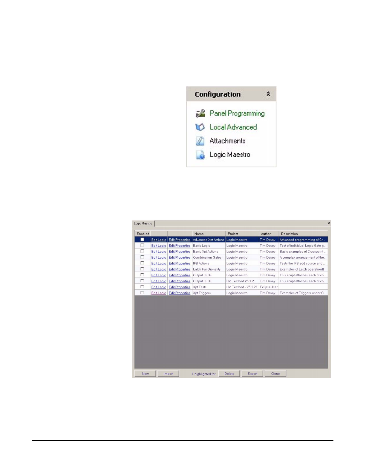
To start Logic Maestro click on the ‘Logic Maestro’ link in the
Configuration menu.
Figure 1-1: ECS Configuration Menu
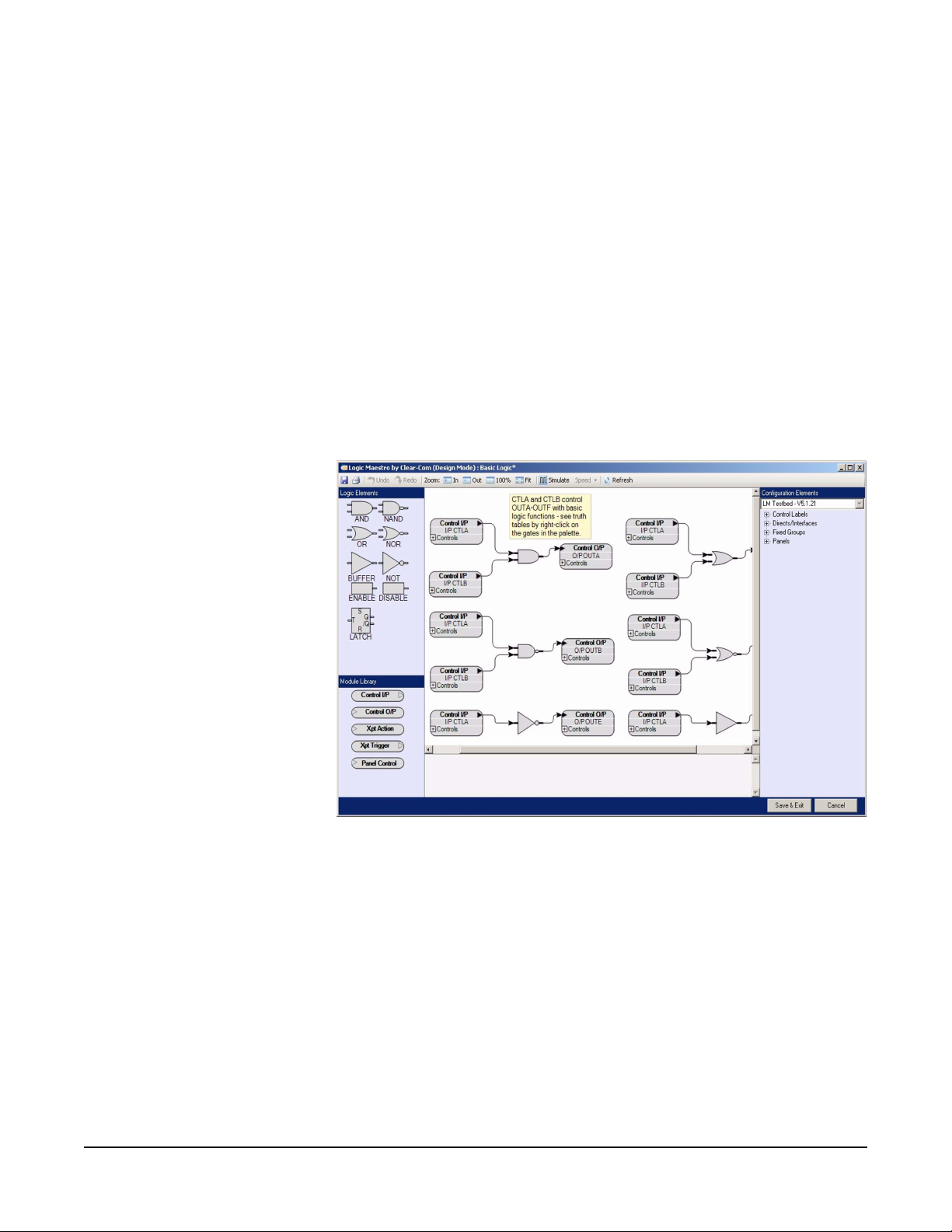
The Logic Maestro design window will be opened displaying the initial
command window with a list of known logic design. The logic design
properties are displayed in seven columns.
1-2
Figure 1-2: Logic Maestro Control Sequence List
At the bottom of the list of control sequences there are five buttons to
access functions to create, delete, import, export and clone control
sequences.
Clear-Com Communication Systems
Eclipse Logic Maestro Instruction Manual
Page 17
CONTROL SEQUENCE PROPERTIES
Enabled Checkbox
The checkbox in the leftmost column of the control sequence list
determines whether the Logic Maestro control sequence is saved with
the system configuration in the database. If the box is checked the
control sequence will be saved with the configuration; if it is not
checked it will not be saved with the configuration and therefore will not
be downloaded to the matrix with the configuration.
Edit Logic Column
The ‘Edit Logic’ column contains links to the source for the selected
control sequence. Clicking on the link will open the logic design
window and display the selected control sequence in the design pane.
Clear-Com Communication Systems
Eclipse Logic Maestro Instruction Manual
Figure 1-3: Control Sequence Display
Edit Properties Column
The ‘Edit Properties’ column contains links to the information for the
selected control sequence. Clicking on this link allows the control
sequence name, project name, author and description to be modified.
1-3
Page 18
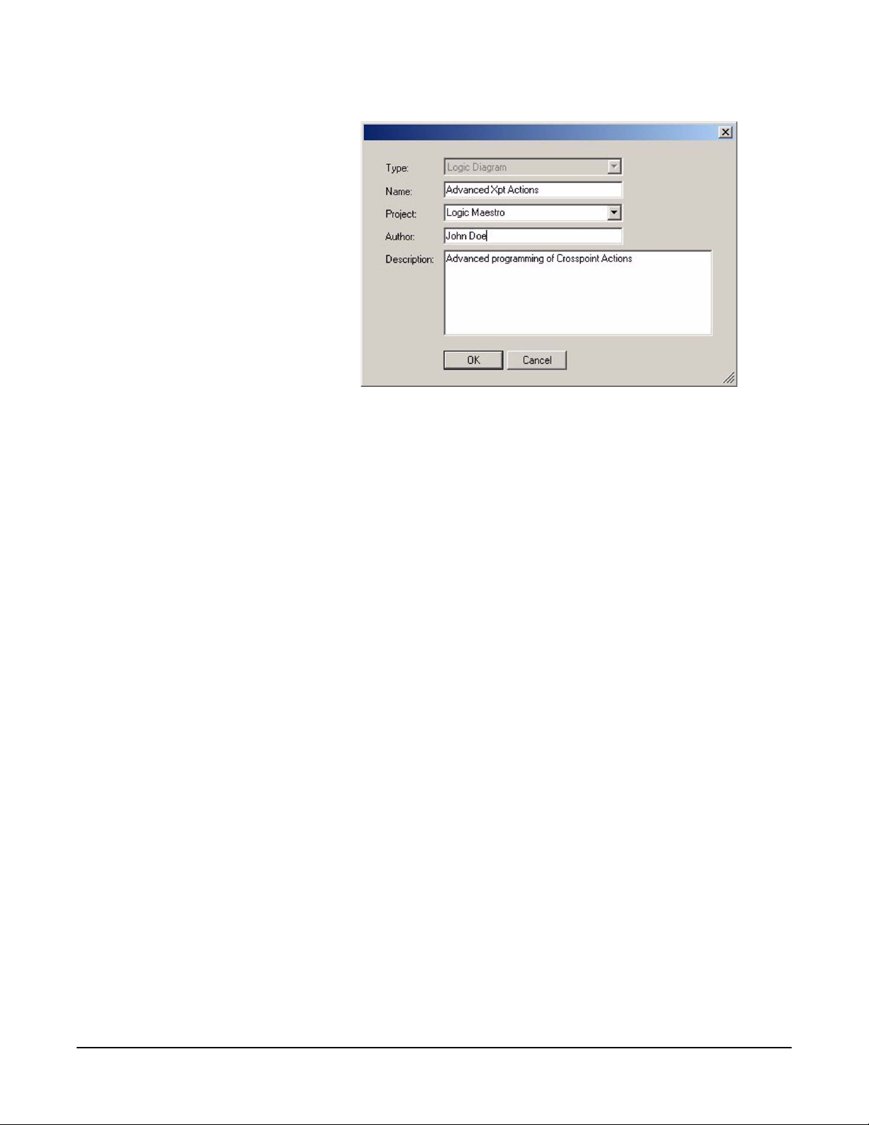
Figure 1-4: Control Sequence Properties
Name
The ‘Name’ column lists the names of the known control sequence
designs. The control sequence design name is edited by selecting the
‘Edit Properties’ link for the required control sequence design.
Project
The ‘Project’ column lists the project names associated with the control
sequences. These project names are optional and are simply to assist
in grouping control sequences together.
Author
The ‘Author’ column lists the names of authors associated with the
control sequences. These author names are optional and are simply
for information.
Description
The ‘Description’ column lists the descriptions associated with the
control sequences. These descriptions are optional and are simply for
information.
1-4
Clear-Com Communication Systems
Eclipse Logic Maestro Instruction Manual
Page 19
FUNCTION BUTTONS
The buttons at the bottom of the logic design window allow control
sequences to be created, deleted, imported from files, exported to files
and cloned.
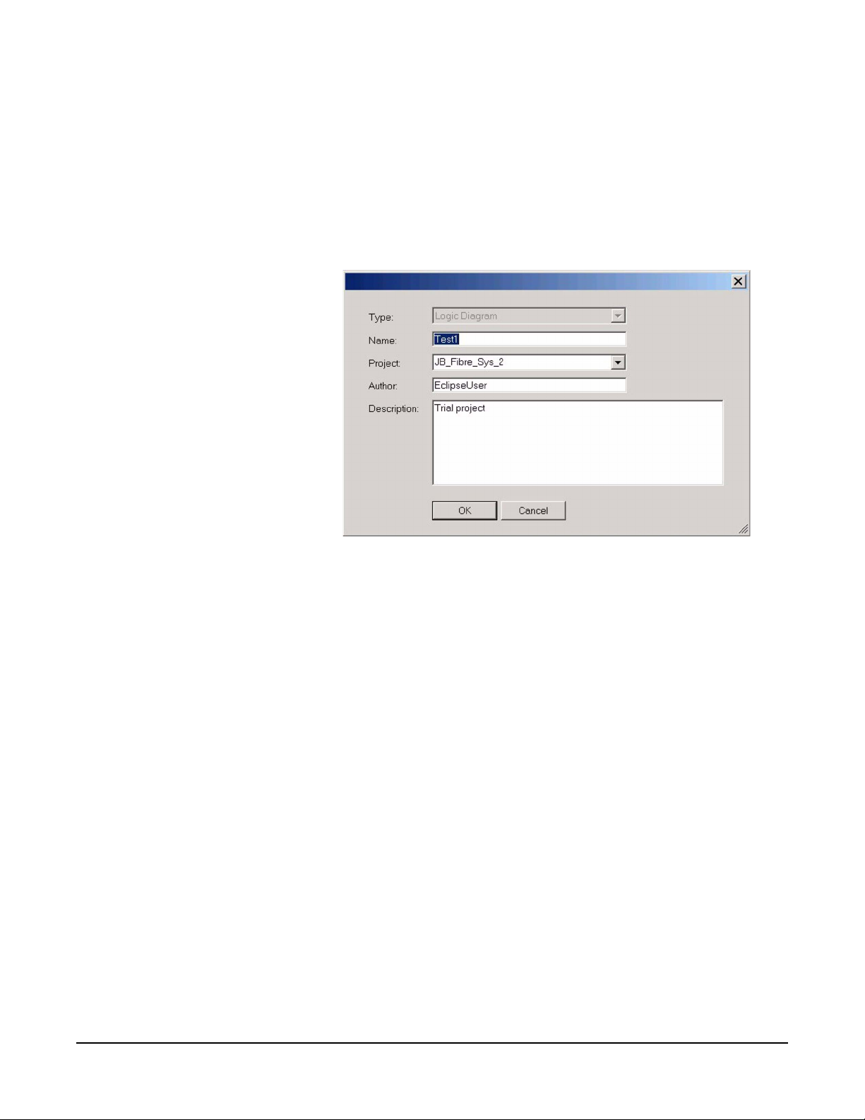
New
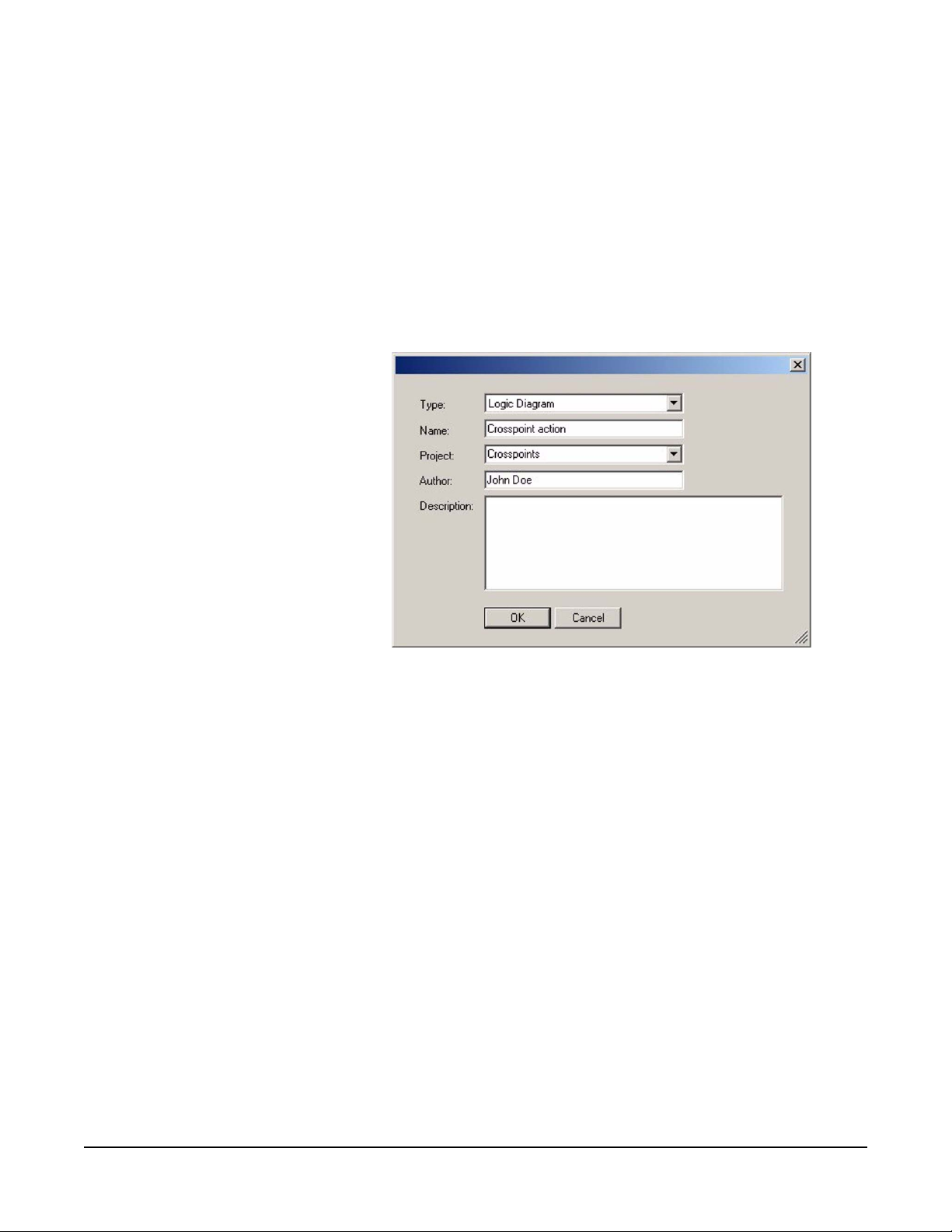
Clicking the ‘New’ button requests the initial information for a new
control sequence design, allowing the design type, design name,
project name, author and a description to be input.
Figure 1-5: New Control Sequence Dialog
The ‘Type’ is selected from a drop-down menu and may be either
‘Logic Diagram’ or ‘Control Macro’. Normally ‘Logic Diagram’ is
selected and the control sequence created using the interactive design
editor.
After entering the required information click on the ‘OK’ button to enter
the Logic Maestro design environment.
The Eclipse Logic Maestro/Control Macro Editor facility is a licensable
option and a license key is required to use Logic Maestro to create
new control sequences. When the logic diagram editor is first started it
will request a license key if one has not already been input.
Clear-Com Communication Systems
Eclipse Logic Maestro Instruction Manual
1-5
Page 20
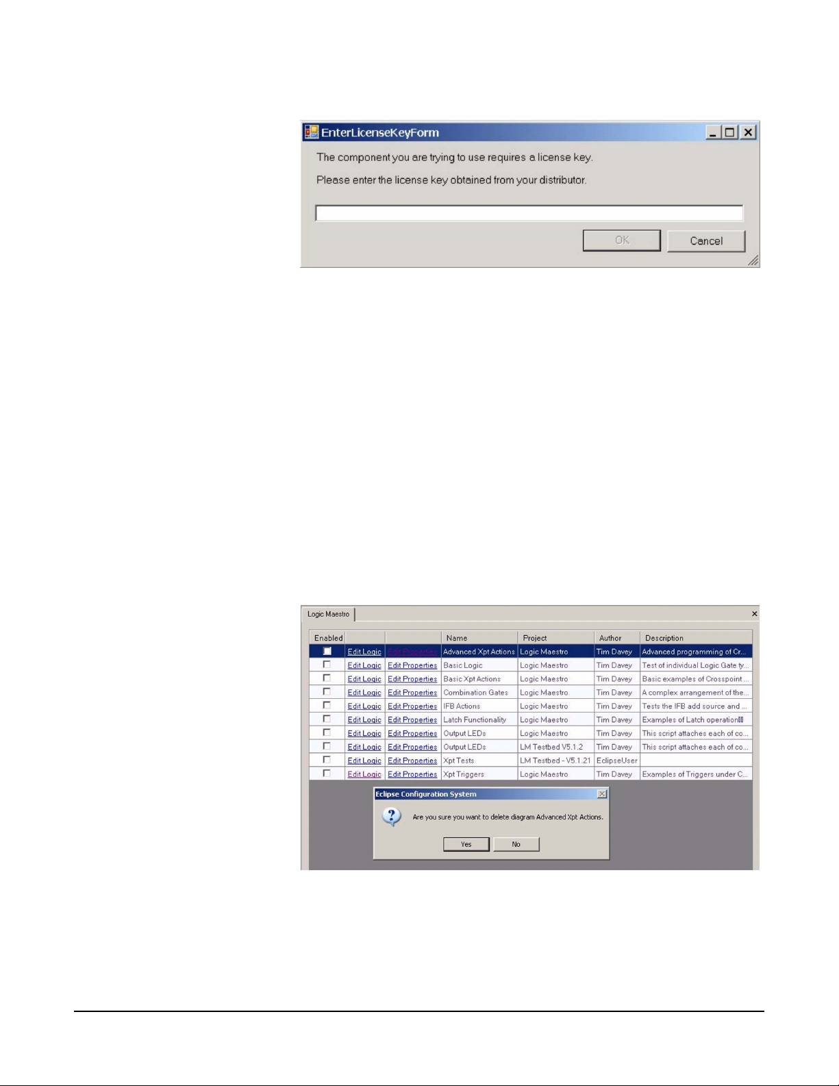
Figure 1-6: License Key Request
Enter the license key obtained from the supplier or distributor and click
on the ‘OK’ button to continue and start the logic diagram editor. If a
valid license key is not entered the editor will exit immediately.
Note: When running under Windows Vista the user must have
administrator rights in order to enter the logic diagram editor
license key.
Delete
The ‘Delete’ button is provides the facility to delete selected control
sequences. Control sequences are selected for deletion by clicking
on the entry to highlight it and clicking on the delete button. Multiple
control sequences can be selected for deletion by pressing the ‘Shift’
key while selecting control sequences. A dialog is displayed to confirm
the action.
1-6
Figure 1-7: Control Sequence Delete Confirmation
Click on the ‘OK’ button to delete the control sequence.
Clear-Com Communication Systems
Eclipse Logic Maestro Instruction Manual
Page 21
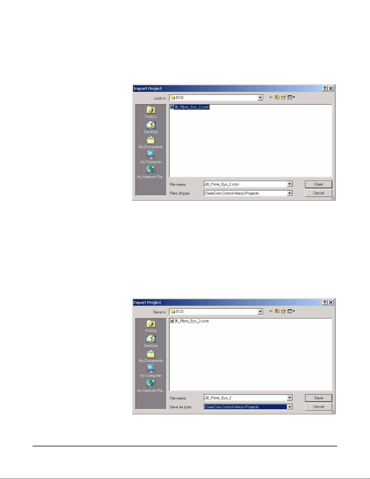
Import
The ‘Import’ button opens a dialogue screen to import a control
sequence file (default file extension .ccm) into Logic Maestro.
Figure 1-8: Control Sequence Import Dialogue
Multiple control sequences can be selected for import by holding down
the ’Shift’ key while selecting the control sequences to be imported.
Export
The ‘Export’ button opens the dialogue screen to export a control
sequence as a control sequence file. These files have a default file
extension of ‘.ccm’. It is recommended that this default file extension is
used.
Clear-Com Communication Systems
Eclipse Logic Maestro Instruction Manual
Figure 1-9: Control Sequence Export Dialogue
1-7
Page 22
Multiple control sequences can be selected for export to a single file by
holding down the ’Shift’ key while selecting the control sequences to
be exported.
Clone
Select the control sequence to be cloned and click on the ‘Clone’
button to open the control sequence clone dialog.
Figure 1-10: Project Clone Dialogue
Enter a new name for the cloned control sequence, and optionally
enter or change the project name, author name and description. Click
on ‘OK’ to create the new control sequence.
Multiple control sequences can be selected for cloning by holding
down the ’Shift’ key while selecting the control sequences to be
cloned.
1-8
Clear-Com Communication Systems
Eclipse Logic Maestro Instruction Manual
Page 23
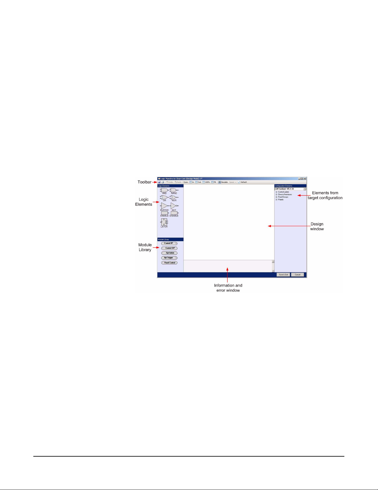
LOGIC PROGRAMMING
Logic Maestro allows control sequences to be created and edited by
dragging and dropping logic elements and library modules onto a
layout and connecting them. Configuration elements are then added
to the module library elements by dragging and drop ping them onto the
appropriate areas of the module library elements to define the items
that are to be used in the control sequence.
The toolbar allows the user to Undo and Redo changes, zoom in or out
of the view, simulate inputs to the logic design, vary the speed of
simulation and refresh the view.
To start a new project click on the ‘New’ tab and enter the project
information into the dialogue screen and click on ‘OK’. The control
logic layout screen is then opened.
Clear-Com Communication Systems
Eclipse Logic Maestro Instruction Manual
Figure 1-11: Logic Maestro Interface
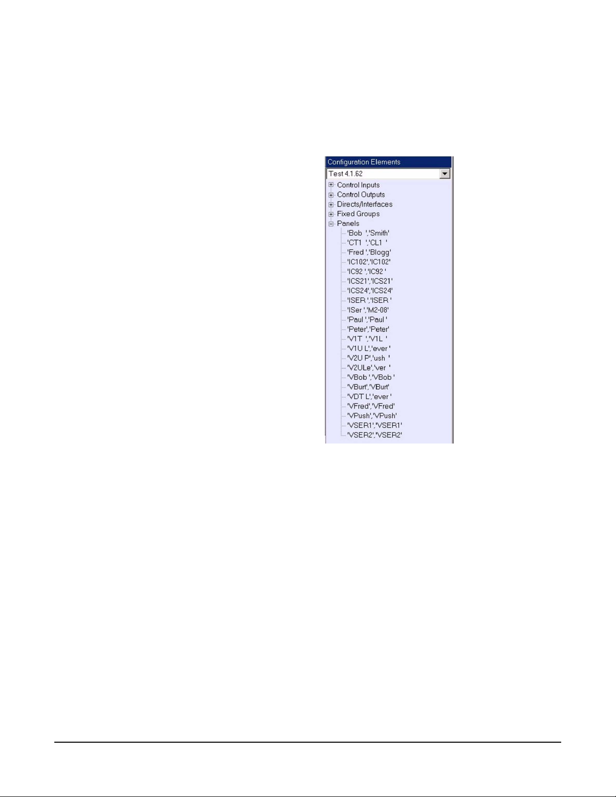
Configuration elements are devices present in the target configuration
(the configuration that the control sequence will be part of). These are
divided into Control Inputs, Control Outputs, Directs/Interfaces, Fixed
Groups and Panels. To select a configuration element click on the
group the required configuration element belongs to and a list of all the
elements in that category will be displayed in the configuratio n element
pane.
Comments can be added to the control sequence design in two ways:
• Placing the mouse pointer over the design pane but not over a design
element and right clicking will create a free-floating comment box that
can be edited with the text of the comment. Double click on the
comment box to highlight and edit the comment text. Free floating
comments can be moved around the design panel using the mouse.
• Placing the mouse pointer over the title of a library module or over a
logic element and right clicking will open a drop down menu of
1-9
Page 24
options. Selecting ‘Add Comment’ will create a comment attached to
the module or logic element. Double click on the comment box to
highlight and edit the comment text. Attached comments can be
moved around the design panel using the mouse but will always
remain connected to the target item.
Figure 1-12: List of Configuration Elements
In the case of devices with talk and listen labels both labels are
displayed in the list in the format ‘talk label’,’listen label’. Devices that
do not have talk and listen labels are identified by name.
Logic elements can be dragged into the design pane and placed for
connection to other elements.
To connect a control input to a logic element simply place the mouse
pointer over the connection point on the control input, left click and
hold, and drag the connection to the required connection point on the
logic element and release the mouse button. The same process is
used to connect the output from a logic element to a control output.
1-10
Clear-Com Communication Systems
Eclipse Logic Maestro Instruction Manual
Page 25
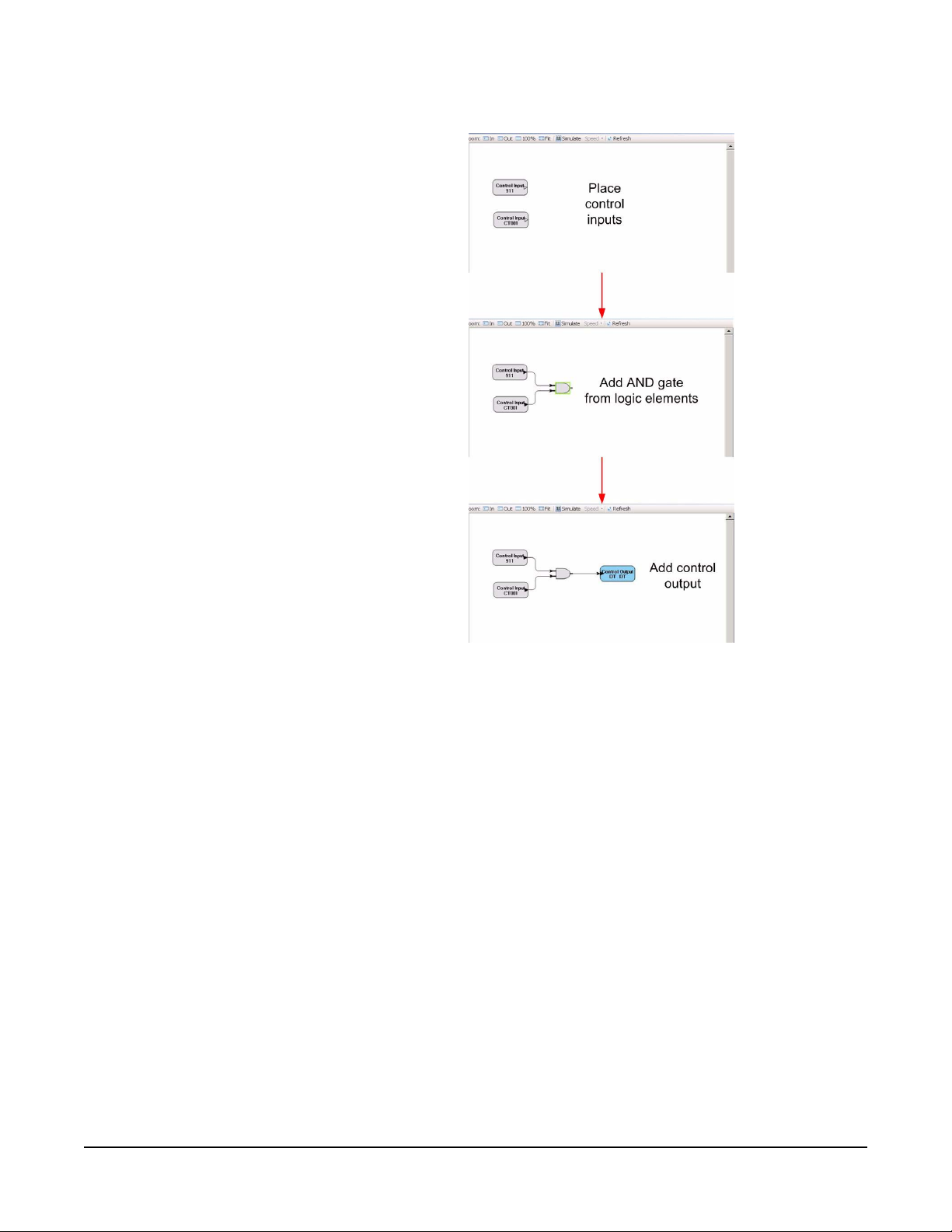
Figure 1-13: Example Control Sequence
Click on the ‘Simulate’ button on the toolbar to test the logic for errors.
When simulation mode is active double clicking with the left mouse
button on a logic input will invert the current state of the input unless it
is an enable or disable logic element. When an element in the design
is off it is colored dark grey , when o n it is white. Setting an input to true
allows the result of the logic design to be checked.
The speed of the simulation can be set to normal, divided by ten or
divided by forty by clicking on the ‘Speed’ button on the toolbar and
selecting the required speed from the menu. The slower speeds allo w
the design to be checked for race conditions that might occur if there
are multiple paths between elements with dif ferent time delays in them.
Right clicking on a control sequence element will open a drop down
menu allowing the element to be deleted, cut or copied. A comment
can also be added. In the case of logic elements the type of logic
element can also be changed.
Clear-Com Communication Systems
Eclipse Logic Maestro Instruction Manual
1-11
Page 26
MODULE LIBRARY
The module library provides control items which can be programmed
with physical devices such as panel keys, direct interfaces and control
labels. The physical items are then acted upon by the control items to
create logic inputs and outputs, create a udio p aths or change the st ate
of panel hardware.
Control Input
Control inputs are used to provide inputs to the control sequence when
a control is active. The control inputs are triggered by controls set up
in ECS by the Control Manager and are usually General Purpose
Inputs (GPIs). These may be attached to devices such as
footswitches. Controls set up in ECS using the Control Manager may
also be assigned to keys under Panel Programming. In this case
activating the panel key will act as a control input.
To set up a control input drag and drop a ‘Control I/P’ module from the
‘Module Library’ onto the design pane.
Figure 1-14: Control Input Module
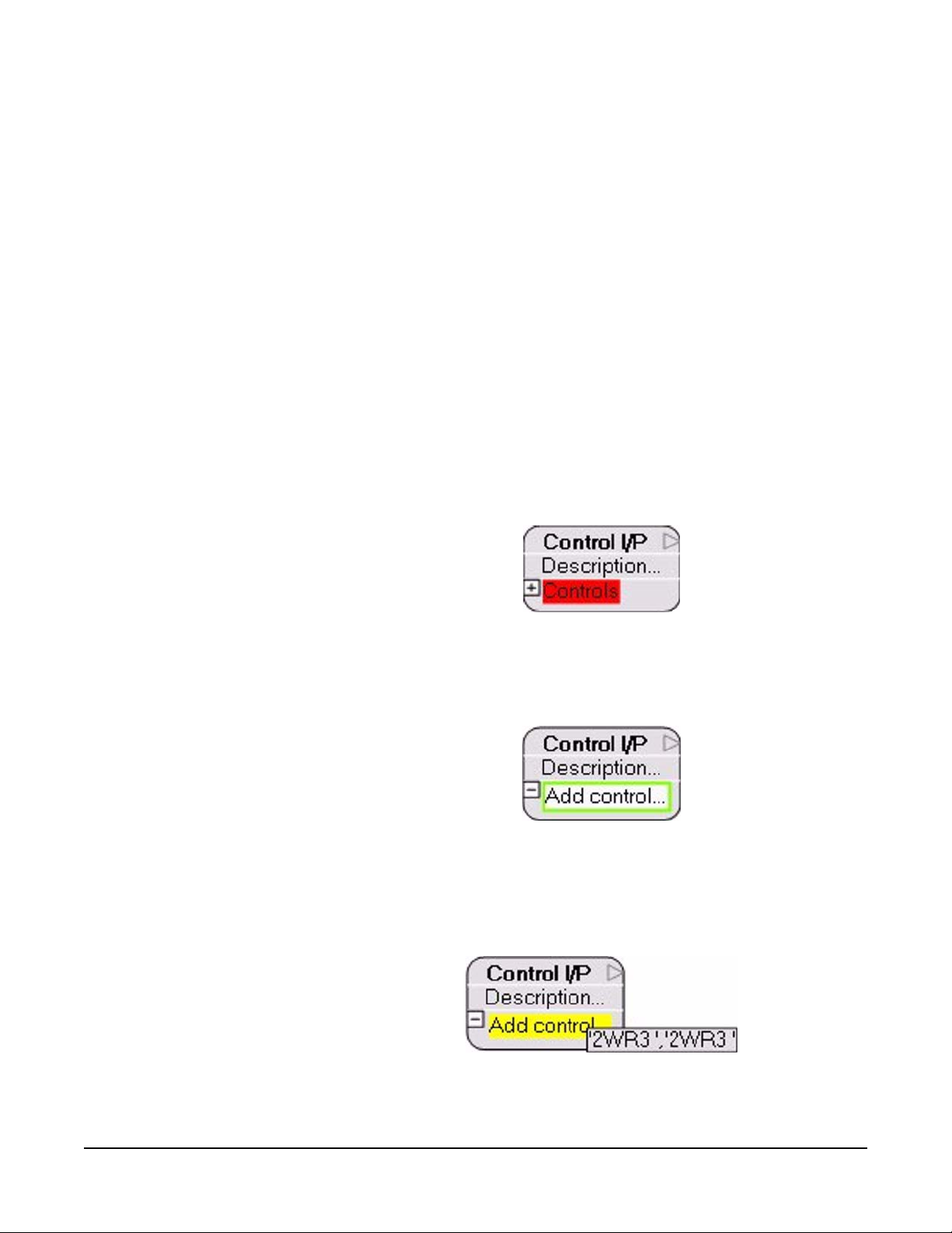
To add a control click on the ‘Controls’ menu to open it and display the
‘Add control’ item.
Figure 1-15: Control Input Menu
Drag and drop an item from the list of control labels onto the ‘Add
control’ item to add it to the list of controls that will trigger the Control
Input function.
Figure 1-16: Adding a Control to the Control Input List
1-12
Clear-Com Communication Systems
Eclipse Logic Maestro Instruction Manual
Page 27
Alternatively control labels can be dragged and dropped directly onto
the unexpanded ‘Controls’ menu and they will be added to the controls
list.
Multiple control labels can be added to the control input module to
create a list of control labels that will activate the logic input from the
control input module.
Figure 1-17: Added Further Controls to a Control Input
Dragging and dropping a control label on top of a label already in the
controls list will replace that item with the new control label.
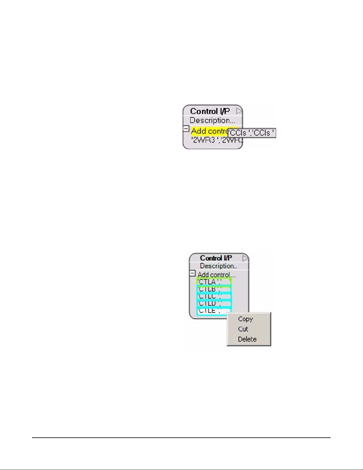
Items on the control list can be selected by left clicking on the items;
multiple items can be selected by holding down the shift key while left
clicking on the items to select them. Right clicking on the selected
control item or items will open a menu giving the options to Copy, Cut
or Delete the items. Alternatively the entire list can be copied by
right-clicking on the unexpanded controls menu and selecting ‘’Copy
this Control list’.
Clear-Com Communication Systems
Eclipse Logic Maestro Instruction Manual
Figure 1-18: Control List Editing
If items from the list of controls are cut or copied they may be pasted
directly into the control list of another control input by right clicking on
the unexpanded controls menu and selecting ‘Add selection’.
To enter a description into the control input double left click on the word
‘Description’ and the description text box is displayed with the current
content highlighted for overtyping.
1-13
Page 28
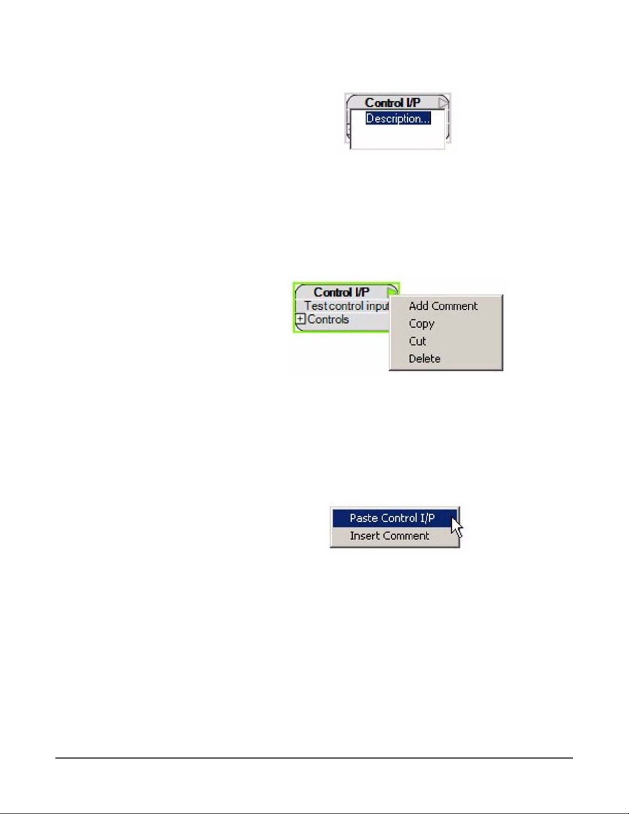
Figure 1-19: Control Input Description
Enter the required description in the text box and then lef t click out side
the text box to close the text box. The description is then displayed on
the control input.
A control input can be copied, cut, deleted or have a comment added
by right clicking on the ‘Control I/P’ title to open the options menu.
Figure 1-20: Copying a Control Input
If a control input is copied or cut it can be pasted back into the design
window complete with the list of assigned controls and the description.
Deletion will remove the control input and ‘Add Comment’ will add an
attached comment as described previously. To paste a copy of a
control input place the mouse pointer over a free space in the design
window and right click to open the menu.
1-14
Figure 1-21: Pasting a Control Input
Click on ‘Insert Comment’ to add a free-floating comment as described
previously.
Control Input Operation
If any of the controls on the list are activated then the control input
module will be set to an active output. The same eff ect can be created
by using multiple control inputs and combining them using ‘OR’ gates
but whereas ‘OR’ gates introduce a 25ms processing delay combining
multiple controls in a list does not introduce a processing delay.
Clear-Com Communication Systems
Eclipse Logic Maestro Instruction Manual
Page 29
Control Output
Control outputs are used to activate outputs when the input state is
true. To set up a control output drag and drop a ‘Control O/P’ module
from the ‘Module Library’ onto the design pane.
Figure 1-22: Control Output Module
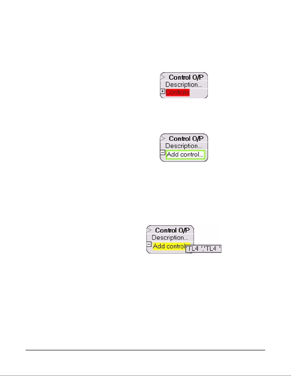
To add a control click on the ‘Controls’ menu to open it and display the
‘Add control’ item.
Figure 1-23: Control Output Menu
Drag and drop an item from the list of control labels onto the ‘Add
control’ item to add it to the list of controls that will be triggered by the
Control Output. The output control labels are set up in ECS by the
Control Manager and are usually General Purpose Outputs (GPOs).
These may be attaches to external devices such as relays to control
devices such as lights or door switches.
Figure 1-24: Adding a Control to the Control Output List
Alternatively control labels can be dragged and dropped directly onto
the unexpanded ‘Controls’ menu and they will be added to the controls
list.
Multiple control labels can be added to the control output module to
create a list of control labels that will be activated by the Control Output
module when it receives an active input.
Clear-Com Communication Systems
Eclipse Logic Maestro Instruction Manual
1-15
Page 30
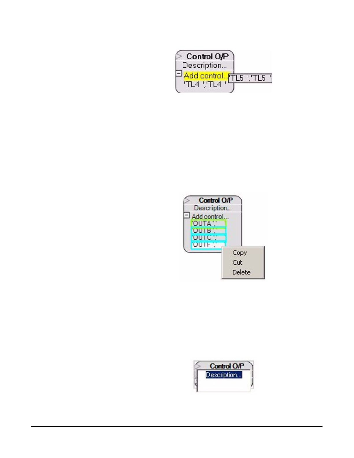
Figure 1-25: Adding Further Controls to a Control Output
Dragging and dropping a control label on top of a label already in the
controls list will replace that item with the new control label.
Items on the control list can be selected by left clicking on the items;
multiple items can be selected by holding down the shift key while left
clicking on the items to select them. Right clicking on the selected
control item or items will open a menu giving the options to Copy, Cut
or Delete the items. Alternatively the entire list can be copied by
right-clicking on the unexpanded controls menu and selecting ‘’Copy
this Control list’.
1-16
Figure 1-26: Control List Editing
If items from the list of controls are cut or copied they may be pasted
directly into the control list of another control output by right clicking on
the unexpanded controls menu and selecting ‘Add selection’.
To enter a description into the control output double left click on the
word ;Description’ and the description text box is displayed with the
current content highlighted for overtyping.
Figure 1-27: Control Output Description
Clear-Com Communication Systems
Eclipse Logic Maestro Instruction Manual
Page 31

Enter the required description in the text box and then lef t click out side
the text box to close the text box. The description is then displayed on
the control output.
A control output can be copied, cut, deleted or have a comment added
by right clicking on the ‘Control O/P’ title to open the options menu.
Figure 1-28: Copying a Control Output
If a control output is copied or cut it can be pasted back into the design
window complete with the list of assigned controls and the description.
Deletion will remove the control output and ‘Add Comment’ will add an
attached comment as described previously. To paste a copy of a
control output place the mouse pointer over a free space in the design
window and right click to open the menu.
Figure 1-29: Pasting a Control Output
Click on ‘Insert Comment’ to add a free-floating comment as described
previously.
Some examples of the use of input and output controls are shown in
Figure 1-30 below.
Clear-Com Communication Systems
Eclipse Logic Maestro Instruction Manual
1-17
Page 32

Figure 1-30: Examples of Controls
Panel Control
The Panel Control module allows logic to be set up to control actions
on panels and keys when the logic input is active. To set up a control
output drag and drop a ‘Panel Control’ module from the ‘Module
Library’ onto the design pane.
The default for a panel control is for panel loudspeaker cut.
1-18
Clear-Com Communication Systems
Eclipse Logic Maestro Instruction Manual
Page 33

Figure 1-31: Default Control Panel Module
The panel control module offers the following options:
• Cut the panel loudspeaker
• Dim the panel loudspeaker
• Select the panel headset
• Mute the panel microphone
• Set the key signalization to red when active
• Set the key signalization to green when active
• Set the key signalization to amber when active
To select a different option open the action menu (‘Loudspeaker Cut’)
and right click on the current option to display the options list.
Clear-Com Communication Systems
Eclipse Logic Maestro Instruction Manual
Figure 1-32: Panel Control Options
Select the panel control option required from the list by left clickin g on
it. The list will be closed and the panel control module display will be
updated according to the option selected.
If a key signalization is selected red, green, amber) the key indication
on the label can be set to one of the options:
• Indication Off
1-19
Page 34

• Indication 1Hz
• Indication 2Hz
• Indication 4Hz
• Indication On
Figure 1-33: Key Signalization Options
The panel override options for key signalization are:
• Activate to Override Local
• Permanent Override of Local
• Advanced Override of Local
Figure 1-34: Panel Override Options for Key Signalization
Drag and drop one or more panels onto the ‘Add Panel’ menu to
configure the panels that will be the subject of the controls. If key
signalizations are required drag and drop the required control labels,
Directs/Interfaces, Fixed Groups or Panels onto the ‘Add Label’ menu.
1-20
Clear-Com Communication Systems
Eclipse Logic Maestro Instruction Manual
Page 35

If a panel loudspeaker, headset or microphone action is selected the
‘Labels’ menu is not available. It is only available when a key
signalization panel action is selected.
If loudspeaker cut, loudspeaker dim, select panel headset or panel
microphone mute are set as the action the options menu for these
actions are:
• Activate to Override Local. Overrides the current setting of the
device if it is currently active. If it is not active the control has no
effect.
Figure 1-35: Panel Override IF Active Example
• Permanent Override of Local. Always overrides the current
setting of the device regardless of whether it is active or not.
Figure 1-36: Permanent Override of Local Example
• Advanced Override of Local. In this case there are two control
inputs to the panel. The first control input must be active for the
second control input to take over the panel function.
Clear-Com Communication Systems
Eclipse Logic Maestro Instruction Manual
1-21
Page 36

Figure 1-37: Advanced Override of Local Example
Crosspoint Trigger
Crosspoint triggers allow audio crosspoints to be used to generate a
control output to another action which may be a control output or a
crosspoint action. Crosspoint triggers are configured with sources and
destinations selected from the lists of fixed groups and panels that
define the crosspoints.
To set a crosspoint trigger drag and drop an ‘Xpt Trigger’ from the
‘Module Library’ pane onto the design pane.
Figure 1-38: Crosspoint Trigger
Trigger Crosspoint Type
1-22
Open the crosspoint type menu and right click on the current type to
display the menu of trigger types.
Clear-Com Communication Systems
Eclipse Logic Maestro Instruction Manual
Page 37

Figure 1-39: Crosspoint Trigger Type Menu
The crosspoint trigger can be set to operate when either source to
destination crosspoints are made or bidirectional crosspoint s are made
between any of the sources and destinations configured. Right click
on the menu item to select the crosspoint trigger type.
Crosspoint Trigger Sources
Crosspoint trigger sources can be added to the list by dragging and
dropping devices from the Direct/Interfaces, Fixed Groups and Panels
lists onto the source list whether or not it is open. If the source list is
opened then dropping a new source onto an existing source will
replace it. If there are no items already assigned to the source list
then the list name will be highlighted in red. If there are items already
assigned the list will not be highlighted but instead will be surrounded
by a green box.
Clear-Com Communication Systems
Eclipse Logic Maestro Instruction Manual
Figure 1-40: Menu Selected
When the menu name is highlighted in yellow the item can be dropped
onto the menu.
Figure 1-41: New Item Added
1-23
Page 38

Right-clicking on ‘Add source...’ will display a menu allowing all the
ports or all the panels in the configuration to be added to the source
list.
Figure 1-42: Adding All Ports or Panels to Crosspoint Trigger
Sources in the list can be copied, cut, deleted or excluded by selecting
the required items from the list and right clicking to display the options
list. Multiple items on the list can be selected by holding down the Shift
key while selecting items.
1-24
Figure 1-43: Crosspoint Trigger Source Options
Items that are cut or copied can be pasted into other source or
destination lists. Deleting an item removes it from the list while the
‘Change to Excluded’ option allows a source to be excluded from
consideration when triggering an output. If a source is excluded it will
be displayed in red. If ‘All Ports’ is present in the source list this cannot
be excluded.
Crosspoint Trigger Destinations
Crosspoint trigger destinations can be added to the list by dragging
and dropping devices from the Direct/Interfaces, Fixed Groups and
Panels lists onto the destination list whether or not it is open. If the
destination list is opened then dropping a new destination onto an
existing destination will replace it. If there are no items already
assigned to the destination list then the list name will be highlighted in
red. If there are items already assigned the list will not be highlighted
but instead will be surrounded by a green box.
Clear-Com Communication Systems
Eclipse Logic Maestro Instruction Manual
Page 39

Figure 1-44: Destination Menu Selected
When the list name is highlighted in yellow the item can be dropped
into the list.
Figure 1-45: New Item Added
Right-clicking on ‘Add destination...’ will display a menu allowing all the
ports or all the panels in the configuration to be added to the
destination list.
Clear-Com Communication Systems
Eclipse Logic Maestro Instruction Manual
Figure 1-46: Adding All Ports or Panels to Crosspoint Trigger
Destinations in the list can be copied, cut, deleted or excluded by
selecting the required items from the list and right clicking to display
the options list. Multiple items on the list can be selected by holding
down the Shift key while selecting items.
1-25
Page 40

Figure 1-47: Crosspoint Trigger Source Options
Items that are cut or copied can be pasted into other source or
destination lists. Deleting an item removes it from the list while the
‘Change to Excluded’ option allows a destination to be excluded from
consideration when triggering an output. Any destination that has
been excluded is shown in red. If ‘All Ports’ is present in the
destination list this cannot be excluded. To re-include a destination
that has been excluded select it and right click to open the actions
menu and select ‘Change to Included’.
Figure 1-48: Pin to Source List Destination Option
1-26
Selecting the ‘Pin to Source List’ option replaces the ‘Destinations’
menu with ‘Dests => Sources’.
To reinstate the ‘Destinations’ menu right click on ‘Dests => Sources’
and select ‘Detach from Source List’.
Clear-Com Communication Systems
Eclipse Logic Maestro Instruction Manual
Page 41

Figure 1-49: Delete Pin to Source List Option
The ‘Dests => Sources’ option replaces the destination list with a
matrix of crosspoints between all the sources in the source list. This is
shown by the crosspoint options menu being replaced by a new ‘All
Xpts’ menu. Right-clicking on the ‘All Xpts’ menu will display a list of
options allowing the crosspoint matrix to be modified.
Figure 1-50: Cross Points Options
The crosspoint options for Pin to Source are:
• All Xpts - triggers on every crosspoint between sources in the
source list. The example below shows the table for sources 1 - 6.
Clear-Com Communication Systems
Eclipse Logic Maestro Instruction Manual
Figure 1-51: All Possible Crosspoints Set as Trigger
1-27
Page 42

• Mix-Minus - triggers on every crosspoint between sources on the
source list except loopback crosspoints that form the diagonal on
the crosspoint matrix. The example below shows the table for
sources 1 - 6.
Figure 1-52: Mix-Minus Crosspoints
• Diagonal - triggers on all loopback crosspoints .i.e. where sources
on the source list are looped back to themselves. The example
below shows the table for sources 1 - 6.
Figure 1-53: Diagonal Crosspoints
1-28
Clear-Com Communication Systems
Eclipse Logic Maestro Instruction Manual
Page 43

Crosspoint Trigger Examples
Examples of the use of crosspoint triggers and actions are shown
below.
Figure 1-54: Crosspoint Trigger for Crosspoint Action
In example Figure 1-54 when source ‘P1’ establishes an audio path to
destination ‘P3’ the crosspoint trigger will be activated to provide an
input to the crosspoint action. The crosspoint action will enable
crosspoints between the same source ‘P1’ and two other destinations
‘P6’ and ‘P7’ at priority 4.
The effect would be that whenever the panel operator ‘P1’ t alks to ‘P3’
the audio will also be routed to ‘P6’ and ‘P7’.
Examples of crosspoint triggers used to trigger control outputs are
shown in Figure 1-55.
Clear-Com Communication Systems
Eclipse Logic Maestro Instruction Manual
1-29
Page 44

Figure 1-55: Crosspoints Triggering Control Outputs
Crosspoints triggers can be used to enable other crosspoints so that a
single key could enable audio feeds from a number of sources to a
number of destinations as shown in Figure 1-56.
1-30
Clear-Com Communication Systems
Eclipse Logic Maestro Instruction Manual
Page 45

Figure 1-56: Crosspoint Triggering Many Actions
There is a constraint on the maximum number of possible actions by
crosspoint triggers and crosspoint actions imposed by system
resources. In general the number of possible triggers times the
number of possible actions should not exceed 4095. So if there are 16
possible triggers specified in an Xpt Trigger and 16 possible crosspoint
actions specified in a Xpt Action the number of actions would be:
16 triggers x 16 actions = 256 events
which would be acceptable. If the result of setting up a system of
crosspoint triggers and crosspoint actions created more than 4095
possible actions an error would be reported when the configuration
was downloaded.
In this case a buffer logic element should be placed between the
crosspoint trigger and crosspoint action. In this way the number of
actions the trigger crosspoint has to make is limited to the number of
trigger crosspoints, which only have to trigger the buffer. The buffer
will then act on the crosspoints in the crosspoint action. An example of
this is shown in Figure 1-57.
Clear-Com Communication Systems
Eclipse Logic Maestro Instruction Manual
1-31
Page 46

Figure 1-57: Many to Many Action with Buffer
Crosspoint actions can also be triggered from control inputs either
directly or through other logic elements.
Crosspoint Action
Crosspoint actions allow crosspoint triggers or control inputs to act on
audio crosspoints in various ways depending on how the crosspoint
action is set up. Crosspoint actions are configured with sources and
destinations selected from the lists of fixed groups and panels that
define the crosspoints.
To set a crosspoint action drag and drop an ‘Xpt Action’ from the
‘Module Library’ pane onto the design pane.
1-32
Figure 1-58: Crosspoint Action
Action Type
The action type menu allows the type of action (enable, disable,
isolate) to be specified, together with the two of crosspoint to be acted
on (source to destination, bidirectional) and the crosspoint priority.
Open the action type menu and right click on the current action to
display the menu of crosspoint actions.
Clear-Com Communication Systems
Eclipse Logic Maestro Instruction Manual
Page 47

Figure 1-59: Crosspoint Actions List
The available crosspoint actions are:
• Enable Action - enable all the crosspoints between the sources
and destinations that satisfy the crosspoint type and priority
criteria except where sources or destinations are marked as
excluded.
• Inhibit Action - inhibit all the crosspoints between the sources and
destinations that satisfy the crosspoint type and priority criteria
except where sources or destinations are marked as excluded.
• Isolate Action - isolate all the crosspoints between the sources
and destinations that satisfy the crosspoint type and priority
criteria except where sources or destinations are marked as
excluded. When isolate actions are applied to bidirectional
crosspoints it will only isolate the source to destination part of the
audio path, not the destination to source part.
Crosspoint Type
Open the crosspoint action menu and right click on the current
crosspoint type to display the menu of crosspoint types.
Clear-Com Communication Systems
Eclipse Logic Maestro Instruction Manual
Figure 1-60: Crosspoint Type List
The crosspoint action can be set to operate when either source to
destination crosspoints are made or bidirectional crosspoint s are made
between any of the sources and destinations configured. Right click
on the menu item to select the crosspoint type.
1-33
Page 48

Crosspoint Priority
The crosspoint priority defines the priority at which the action is applied
to the crosspoints. For a crosspoint action to change the state of a
crosspoint it must be set to a priority higher than the crosspoint.
Figure 1-61: Crosspoint Action Priority
For example in order to override panel talk crosspoints at priority two
with a crosspoint action the action priority must be set to three or
higher.
Crosspoint Action Sources
Crosspoint action sources can be added to the list by dragging and
dropping devices from the Direct/Interfaces, Fixed Groups and Panels
lists onto the source list whether or not it is open. If the source list is
opened then dropping a new source onto an existing source will
replace it. If there are no items already assigned to the source list
then the list name will be highlighted in red. If there are items already
assigned the list will not be highlighted but instead will be surrounded
by a green box.
Figure 1-62: Crosspoint Action Source List
When the menu name is highlighted in yellow the item can be dropped
onto the list.
1-34
Clear-Com Communication Systems
Eclipse Logic Maestro Instruction Manual
Page 49

Figure 1-63: Adding a New Source
Right-clicking on ‘Add source...’ will display a menu allowing all the
ports or all the panels in the configuration to be added to the source
list.
Figure 1-64: Adding All Ports or Panels to Crosspoint Action Source
Sources in the list can be copied, cut, deleted or excluded by selecting
the required items from the list and right clicking to display the options
list. Multiple items on the list can be selected by holding down the Shift
key while selecting items.
Clear-Com Communication Systems
Eclipse Logic Maestro Instruction Manual
Figure 1-65: Crosspoint Action Source Options
Items that are cut or copied can be pasted into other source or
destination lists. Deleting an item removes it from the list while the
‘Change to Excluded’ option allows a source to be excluded from
consideration when acting on crosspoints. Any source that has been
excluded is shown in red. If ‘All Ports’ is present in the source list this
cannot be excluded. To re-include a destination that has been
1-35
Page 50

excluded select it and right click to open the actions menu and select
‘Change to Included’.
Crosspoint Action Destinations
Crosspoint action destinations can be added to the list by dragging and
dropping devices from the Direct/Interfaces, Fixed Groups and Panels
lists onto the destination list whether or not it is open. If the destination
list is opened then dropping a new destination onto an existing
destination will replace it. If there are no items already assigned to the
destination list then the list name will be highlighted in red. If there are
items already assigned the list will not be highlighted but instead will be
surrounded by a green box.
Figure 1-66: Destination Menu Selected
When the list name is highlighted in yellow the item can be dropped
into the list.
Figure 1-67: New Destination Item Added
Right-clicking on ‘Add destination...’ will display a menu allowing all the
ports or all the panels in the configuration to be added to the
destination list.
1-36
Clear-Com Communication Systems
Eclipse Logic Maestro Instruction Manual
Page 51

Figure 1-68: Adding All Ports or Panels to Crosspoint Action
Destinations in the list can be copied, cut, deleted or excluded by
selecting the required items from the list and right clicking to display
the options list. Multiple items on the list can be selected by holding
down the Shift key while selecting items.
Figure 1-69: Crosspoint Action Destination Options
Items that are cut or copied can be pasted into other source or
destination lists. Deleting an item removes it from the destination list
while the ‘Change to Excluded’ option allows a destination to be
excluded from consideration when triggering an output. Any
destination that is excluded is shown in red. If ‘All Ports’ is present in
the destination list this cannot be excluded.
Clear-Com Communication Systems
Eclipse Logic Maestro Instruction Manual
Right clicking on an empty destination list without expanding the list
will display an additional option of ‘Pin to Source List’.
Right clicking on an empty destination list without expanding the list
will display an additional option of ‘Pin to Source List’.
1-37
Page 52

Figure 1-70: Pin to Source List Destination Option
Selecting the ‘Pin to Source List’ option replaces the ‘Destinations’
menu with ‘Dests => Sources’. To reinstate the ‘Destinations’ menu
right click on ‘Dests => Sources’ and select ‘Detach from Source List’.
Figure 1-71: Delete Pin to Source List Option
The ‘Dests => Sources’ option replaces the destination list with a
matrix of crosspoints between all the sources in the source list. This is
shown by the crosspoint options menu being replaced by a new ‘All
Xpts’ menu. Right-clicking on the ‘All Xpts’ menu will display a list of
options allowing the crosspoint matrix to be modified.
1-38
Figure 1-72: Crosspoint Pin to Source Options
The crosspoint options for Pin to Source are:
• All Xpts - acts on every crosspoint between sources in the source
list. The example below shows the table for sources 1 - 6.
Clear-Com Communication Systems
Eclipse Logic Maestro Instruction Manual
Page 53

Figure 1-73: All Possible Crosspoints Set as Action
• Mix-Minus - acts on every crosspoint between sources on the
source list except loopback crosspoints that form the diagonal on
the crosspoint matrix. The example below shows the table for
sources 1 - 6.
Clear-Com Communication Systems
Eclipse Logic Maestro Instruction Manual
Figure 1-74: Mix-Minus Crosspoints
• Diagonal - triggers on all loopback crosspoints .i.e. where sources
on the source list are looped back to themselves. The example
below shows the table for sources 1 - 6.
1-39
Page 54

Figure 1-75: Loopback Crosspoints
1-40
Clear-Com Communication Systems
Eclipse Logic Maestro Instruction Manual
Page 55

LOGIC ELEMENTS
Logic elements are used to perform logical operations on the outputs
of control sequence elements and pass the result to the input of other
control sequence elements. This allows complex sequences of
actions depending on various conditions to be built up and
programmed into the matrix system. Right click on the logic elements
in the Logic Elements pane to display an options menu. This menu
allows the user to display a truth table for the logic element or copy the
logic element to the design window.
Logic elements can be inserted existing connections by right-clicking
on the connection to display the options menu and selecting ‘Insert
Gate Type’. A list of logic elements will be displayed for insertion into
the connection.
Figure 1-76: Inserting a Logic Element into a Connection
The logic elements available are described below.
AND Gate
Combines two or more inputs to generate a single output. Th e de fault
is two inputs but by right clicking on the AND gate to display the
options menu additional inputs can be added. Unused inputs will
default to the TRUE state. The output is only true if all the inputs are
true. The AND gate adds a 25ms processing delay.
Input A Input B Output
False False False
False True False
True False False
True True True
Table 1-1: Truth Table for AND Logic Element
Clear-Com Communication Systems
Eclipse Logic Maestro Instruction Manual
1-41
Page 56

Right clicking on the logic element in the design window displays an
options menu.
Figure 1-77: Menu Options for AND Logic Element
• Add Comment - add a comment to the logic element.
• Delete - delete logic element from design window.
• Cut - cut logic element from design window.
• Copy - copy logic element on design window.
• Add Input - add an input to the logic element.
• Change Gate Type - replace the logic element with one selected
from the drop-down list.
NAND Gate
Combines two or more inputs to generate a single output. Th e de fault
is two inputs but by right clicking on a NAND gate to display the menu
additional inputs can be added. Unused inputs will default to the
TRUE state. The output is only true if at least one input is false. The
NAND gate adds a 25ms processing delay.
Input A Input B Output
False False True
False True True
True False True
True True False
1-42
Table 1-2: Truth Table for NAND Logic Element
Clear-Com Communication Systems
Eclipse Logic Maestro Instruction Manual
Page 57

Right clicking on the logic element in the design window displays an
options menu.
Figure 1-78: Menu Options for NAND Logic Element
• Add Comment - add a comment to the logic element.
• Delete - delete logic element from design window.
• Cut - cut logic element from design window.
• Copy - copy logic element on design window.
• Add Input - add an input to the logic element.
• Change Gate Type - replace the logic element with one selected
from the drop-down list.
OR Gate
Combines two or more inputs to generate a single output. Th e de fault
is two inputs but by right clicking on an OR gate to display the menu
additional inputs can be added. Unused inputs will default to the
TRUE state. The output is only true if one or more inpu ts are true. The
OR gate adds a 25ms processing delay.
Input A Input B Output
False False False
False True True
True False True
True True True
Clear-Com Communication Systems
Eclipse Logic Maestro Instruction Manual
Table 1-3: Truth Table for OR Logic Element
Right clicking on the logic element in the design window displays an
options menu.
1-43
Page 58

Figure 1-79: Menu Options for OR Logic Element
• Add Comment - add a comment to the logic element.
• Delete - delete logic element from design window.
• Cut - cut logic element from design window.
• Copy - copy logic element on design window.
• Add Input - add an input to the logic element.
• Change Gate Type - replace the logic element with one selected
from the drop-down list.
NOR Gate
Combines two or more inputs to generate a single output. Th e de fault
is two inputs but by right clicking on a NOR gate to display the menu
additional inputs can be added. Unused inputs will default to the
TRUE state. The output is only true if all inputs are false. The NOR
gate adds a 25ms processing delay.
Input A Input B Output
1-44
False False True
False True False
True False False
True True False
Table 1-4: Truth Table for NOR Logic Element
Right clicking on the logic element in the design window displays an
options menu.
Clear-Com Communication Systems
Eclipse Logic Maestro Instruction Manual
Page 59

Figure 1-80: Menu Options for NOR Logic Element
• Add Comment - add a comment to the logic element.
• Delete - delete logic element from design window.
• Cut - cut logic element from design window.
• Copy - copy logic element on design window.
• Add Input - add an input to the logic element.
• Change Gate Type - replace the logic element with one selected
from the drop-down list.
BUFFER Element
Used between a crosspoint trigger and a crosspoint action to reduce
the system resource usage. There is a constraint on the maximum
number of possible actions by crosspoint triggers and crosspoint
actions imposed by system resources. In general the number of
possible triggers times the number of possible actions should not
exceed 4095. So if there are 16 possible triggers specified in a
crosspoint trigger and 16 possible crosspoint actions specified in a
crosspoint action the number of actions would be:
16 triggers x 16 actions = 256 events
Clear-Com Communication Systems
Eclipse Logic Maestro Instruction Manual
which would be acceptable. If the result of setting up a system of
crosspoint triggers and crosspoint actions created more than 4095
possible actions an error would be reported when the configuration
was downloaded.
In this case a buffer logic element should be placed between the
crosspoint trigger and crosspoint action. In this way the number of
actions the trigger crosspoint has to make is limited to the number of
trigger crosspoints, which only have to trigger the buffer. The buffer
will then act on the crosspoints in the crosspoint action.
The BUFFER element adds a 25ms processing delay.
1-45
Page 60

Input A Output
False False
True True
Table 1-5: Truth Table for BUFFER Logic Element
Right clicking on the logic element in the design window displays an
options menu.
Figure 1-81: Menu Options for BUFFER Logic Element
• Add Comment - add a comment to the logic element.
• Delete - delete logic element from design window.
• Cut - cut logic element from design window.
• Copy - copy logic element on design window.
• Change Gate Type - replace the logic element with one selected
from the drop-down list.
NOT Element
A NOT element inverts the input so that when the input is OFF the
output is ON; when the input is ON the output is OFF. The NOT
function adds a 25ms processing delay.
Input A Output
False True
True False
1-46
Table 1-6: Truth Table for NOT Logic Element
Clear-Com Communication Systems
Eclipse Logic Maestro Instruction Manual
Page 61

Right clicking on the logic element in the design window displays an
options menu.
Figure 1-82: Menu Options for NOT Logic Element
• Add Comment - add a comment to the logic element.
• Delete - delete logic element from design window.
• Cut - cut logic element from design window.
• Copy - copy logic element on design window.
• Change Gate Type - replace the logic element with one selected
from the drop-down list.
LATCH Element
The latch element creates a true or false output that can be set or
cleared by inputs to toggle, set or reset inputs. The latch element will
maintain the state it is set to until that state is changed via a set, reset
or toggle.
Reset Set Toggle Q /Q
True X X False True
False True X True False
False False F -> T /Q Q
X False T -> F Q /Q
Table 1-7: Truth Table for LATCH Logic Element
Right clicking on the logic element in the design window displays an
options menu.
Clear-Com Communication Systems
Eclipse Logic Maestro Instruction Manual
1-47
Page 62

Figure 1-83: Menu Options for LATCH Logic Element
• Add Comment - add a comment to the logic element.
• Delete - delete logic element from design window.
• Cut - cut logic element from design window.
• Copy - copy logic element on design window.
The latch element can be used with the toggle input only connected
and the set and reset inputs not connected. In this case the latch will
change state when it is toggled by an external input. The toggle
operates on the rising edge of an input so if the input goes to true the
latch will toggle to the opposite to its current state. When the toggle
input goes false the latch will remain in its current state until the toggle
input goes true again.
1-48
Clear-Com Communication Systems
Eclipse Logic Maestro Instruction Manual
Page 63

Figure 1-84: Latch Sequence Using Toggle
This allows a toggle input to toggle normal and inverted outputs so that
input events will enable outputs which then remain enabled until the
latch is toggled again or reset.
An example of using the latch with toggle, set and reset connected is
shown in Figure 1-85.
Clear-Com Communication Systems
Eclipse Logic Maestro Instruction Manual
1-49
Page 64

Figure 1-85: Latch Example using All Inpu ts
The LATCH function adds a 25ms processing delay.
ENABLE Element
The ENABLE logic element allows a logic true or always on input t o be
placed in a control sequence design. This allows control sequences to
be created with temporary external inputs or stubs which are known to
be always on. This logic element is useful for testing the logic design.
Figure 1-86: Menu Options for Enable Logic Element
• Add Comment - add a comment to the logic element.
1-50
• Delete - delete logic element from design window.
• Cut - cut logic element from design window.
Clear-Com Communication Systems
Eclipse Logic Maestro Instruction Manual
Page 65

• Copy - copy logic element on design window.
• Change Gate Type - replace the logic element with one selected
from the drop-down list.
DISABLE Element
The DISABLE logic element allows a logic false or always off input to
be placed in a control sequence design. This allows control sequence
designs to be created with temporary external inputs or stubs which
are known to be always off. This logic element is useful for testing the
logic design.
Figure 1-87: Menu Options for Disable Logic Element
• Add Comment - add a comment to the logic element.
• Delete - delete logic element from design window.
• Cut - cut logic element from design window.
• Copy - copy logic element on design window.
• Change Gate Type - replace the logic element with one selected
from the drop-down list.
Some Example of the use of logic elements are shown in Figure 1-88.
Clear-Com Communication Systems
Eclipse Logic Maestro Instruction Manual
1-51
Page 66

Figure 1-88: AND, NAND and BUFFER Logic Elements
1-52
Clear-Com Communication Systems
Eclipse Logic Maestro Instruction Manual
Page 67

APPENDIX A
2
CONTROL MACRO
EDITOR
INTRODUCTION TO CONTROL MACRO EDITOR
Control macros allow the configuration map that controls the matrix
operation to be directly modified via control macros. Each control
macro contains a series of commands with each defined command
representing an action carried out on an object in the configuration. An
object may be a port, an input or output device or label.
The main use of control macro scripts is to select controls which have
already been configured using the ECS client, and modify the actions
that they trigger when activated.
Each defined command is named and can have multiple inputs and
outputs and combination logic. These commands take the form of
actions to be associated with controls, and the control macro editor will
assist the author by providing an overview of available actions and the
parameters each requires in order to function.
Conditional logic is available (i.e. with AND, OR logic), with examples
and code hints supplied by the control macro editor environment.
Examples of the use of control macros when coupled with ECS
Controls and port configuration are:
• To enable or disable a route between any source and a named
destination which may be conditional on the status of other
Controls, Route based Controls or GPIs.
• To enable or disable a named panel’s loudspeaker (dimming/ muting)
• To remotely enable a named panel’s microphone muting
• To remotely enable a named panel’s headset/ microphone selection
• To remotely enable a named panel’s nominated Key LED signal
activation
• To remotely enable a named panel’s nominated Relay control
Clear-Com Communication Systems
Eclipse Logic Maestro Instruction Manual
2-1
Page 68

The control macro editor enables the user to:
• Define control macros
• Reference control macros by name
• Assign named macro functions to controls
Note: Control Macros are only available to ECS V4.0 or later.
The Control Macro Application is a stand-alone application
requiring a license key.
ECS then imports the macros for use within the ECS
environment.
2-2
Clear-Com Communication Systems
Eclipse Logic Maestro Instruction Manual
Page 69

CONTROL MACRO LANGUAGE
The Microsoft .NET Framework is used to provide the scripting facility
through the use of dynamic code generation (CodeDOM). This
provides the facility to compile control macro into a binary file (an
Assembly) rather than the more traditional ‘interpreted’ control macro
of other languages such as VBScript.
Using the .NET Framework as the scripting environment provides the
stability and support that the framework has, along with gaining from
the .NET Framework features of:
• Managed application environment
• Garbage collector memory management
• Control macros are written in C#
EXAMPLE CONTROL MACRO
The following is an example of a control macro created using the
control macro editor.
Control Macro ExampleScript
using System; // automatically generated
using ClearCom.ScriptHost;
using ClearCom.ScriptLibrary;
using ClearCom.Entities;
using EMS.MapClient;
using EMS.MapClient.Tables;
using EMS.MapClient.Tables.Actions;
namespace CustomControlMacros
{
public class CustomMacro : ScriptBase
{
public override void OnUserStart()
{
// User Script entered here
Control redLightControl = ExistingControlFromLabel(“RDLT”);
// gets an already existing Control, set up from the Control Manager within the ECS client and
allows it to be programmed
redLightControl.Triggers(new InhibitRoute(5, 6));
// When the red light control is fired (studio moves into Live mode) the route between ports 5 and
6 is
// inhibited. The control editor prompts the script author for either a port number or port name
redLightControl.Triggers(new ChangeStatus(“DIR”, HardwareStatus.LoudspeakerCut);
// changes a large number of panel properties by selecting a panel by name and then triggering a
change
redLightControl.Triggers(new ChangeStatus(“DIR”, 5);
// Changes LED 5 on panel DIR
}
}
}
Clear-Com Communication Systems
Eclipse Logic Maestro Instruction Manual
2-3
Page 70

CONTROL MACRO EDITOR
To create and edit the Control Macro, a control macro editor is
provided. This consists of:
• A main control macro editor window
• An object browser
• A message window
An illustration of the control macro editor is shown below.
2-4
Figure 2-1: Control Macro Editor Screen
CONTROL MACRO EDITOR WINDOW
The control macro editor window provides full access for editing the
control macro scripts while also providing assistance to the user in the
form of coloured syntax, ‘intellisense’ (offering cont ext sensitive coding
options) and code completion.
OBJECT BROWSER
The Object Browser gives a complete display of the objects and logic
available to be used to construct control macros. This gives a detailed
view of all the contained objects, their constructors, methods and
properties. This view will be generated using the powerful reflection
capability that is part of the .NET Framework.
Clear-Com Communication Systems
Eclipse Logic Maestro Instruction Manual
Page 71

MESSAGE WINDOW
The Message Window will provide feedback to the user of any
validation issues when parsing the co ntrol macro. These issues will be
flagged as either warnings or errors.
RUNNING CONTROL MACROS
Control macros are run at download time and follow a two stage
approach of validation and building of the control macro.
The validation stage checks the control macro for warnings or errors
which will be reported back to the user. Any errors will prevent the
control macro from being compiled.
When the control macro has passed the validation stage, the control
macro will be compiled into an Assembly using the Microsoft .NET
Framework code compiler. This Assembly is then cached and will only
be refreshed if the control macro itself is changed. It is then run at
download time, with the output (usually the addition of rack-specific
map objects) being sent to the frame together with the ECS-derived
configuration.
STARTING THE CONTROL MACRO EDITOR
The control macro editor is accessed from Logic Maestro by clicking
on the ‘New’ button and selecting ‘Control Macro’ from the drop-down
‘Type’ menu.
Figure 2-2: Control Macro Editor from Logic Maestro
After entering the required fields click on the ‘OK’ button to open the
control macro editor.
Clear-Com Communication Systems
Eclipse Logic Maestro Instruction Manual
Saved control macro files have the same file extension of .ccm as logic
maestro files and will be listed with logic maestro files. If the ‘Edit
2-5
Page 72

Logic’ link is selected for a control macro file the control macro editor
will be started automatically rather than the logic diagram editor.
The control macro editor can also be started using a desktop shortcut
to the executable if required but this useage is not recommended.
The Eclipse Macro facility is a licensable option and a license key is
required to use the editor to create new control macros. When the
editor is first started it will request a license key if one has not already
been input.
Figure 2-3: License Key Request
Enter the license key obtained from the supplier or distributor and click
on the ‘OK’ button to continue and start the control macro editor. If a
valid license key is not entered the control macro editor will exit
immediately.
Note: When running under Windows Vista the user must have
administrator rights in order to enter the control macro editor
license key.
When the editor is started from Logic Maestro it will display the three
windows ready to start a new control macro (if started using the ‘New’
button) or load an existing macro.
2-6
Clear-Com Communication Systems
Eclipse Logic Maestro Instruction Manual
Page 73

Figure 2-4: Initial Macro Control Macro Editor Display
Clear-Com Communication Systems
Eclipse Logic Maestro Instruction Manual
2-7
Page 74

CONFIGURATION ENTITIES
Click on the ‘Configuration Entities’ tab of the object browser to select
the system configuration that is to be used by the contro l macro editor.
A drop down menu of all the available system configurations is
displayed below the window title.
Figure 2-5: Configuration Selection
After a system configuration has been selected the entities that exist in
that configuration are displayed in the object browser window under
the headings:
• Gpsf - General Purpose Specific Functions
• Group - fixed groups and sort groups defined in ECS
• Port - system ports defined as Direct in ECS
• Conf - party lines (conferences) defined in ECS
• Port - system ports defined as panels in ECS
• Relay - relays that can be set open or closed
• Route - routes between panels defined in ECS
Each item can be opened to display a list of all the entities of this type
in the currently selected system configuration. If the configuration
does not include any entities of a type the heading for that entity type is
not displayed.
If a new ECS element is made while the control macro editor is
opened, then:
2-8
Clear-Com Communication Systems
Eclipse Logic Maestro Instruction Manual
Page 75

1. In ECS Save the configuration(s).
2. Re-select the configuration(s) from the configuration task in order to
force the macro editor to refresh its copy of the configuration(s).
Figure 2-6: Configuration Entities List
These entities contained in the system configuration selected may be
referenced in the control macro as required but the control macro will
be specific to that system configuration and should not be used with
any other system configuration as it may fail or produce unexpected
results.
Clear-Com Communication Systems
Eclipse Logic Maestro Instruction Manual
2-9
Page 76

AVAILABLE MODULES
Click on the ‘Available Modules’ tab in the object browser to display the
menus for the objects used to create the macros. These are divided
into the ‘ClearCom’ modules to construct programs to modify the map
and ‘Shared’ to provide logging and debug capability.
CLEARCOM
Click on the ‘ClearCom’ item and expand the menus to show the object
classes available.
Figure 2-7: ClearCom Module Libraries
Entities
The entities section is divided into Attachment Objects which are
associated with components, Control Objects that act on system
components, Entity Objects that act on the state of system
components and Port Objects that act on system ports.
2-10
Clear-Com Communication Systems
Eclipse Logic Maestro Instruction Manual
Page 77

Figure 2-8: Entity Libraries
Attachment Objects
When the attachment objects item is selected the list will be exp and ed
to display the attachment objects available and the logic operations
that may be used with attachment objects. Attachment objects are
attached to components to set or get the properties of those
components such as parameters.
Examples of attachment objects are relays, routes and speed dials.
Clear-Com Communication Systems
Eclipse Logic Maestro Instruction Manual
Figure 2-9: Attachment Objects Library
2-11
Page 78

To use an attachment object select the required object by right clicking
over it and then dragging it over to the edit window and dropping it in
the required position.
When an attachment object is dropped into the control macro the
editor will prompt for information such as whether the object is to set or
get the component parameter and depending on this any other
information that is required such as parameters and how to return the
information.
Figure 2-10: Example of Attachment Object Properties
Control Objects
Control objects act on the components to change their properties in
some way. When a control object is dropped into the editor window
the editor will prompt for the required settings and parameters for that
object.
Control objects are controls created in ECS using the Control Manager
function accessed from the Setup Eclipse menu.
2-12
Clear-Com Communication Systems
Eclipse Logic Maestro Instruction Manual
Page 79

Figure 2-11: Control Objects List
An example of the use of a control object is:
HSON.Triggers(ControlActions.CutLoudspeaker(D4222));
where CutLoudspeaker is the control.
Entity Objects
Entity objects act on the components to change their state in some
way. When an entity object is dropped into the editor window the
editor will prompt for the required settings and parameters for that
object.
Clear-Com Communication Systems
Eclipse Logic Maestro Instruction Manual
2-13
Page 80

Figure 2-12: Entity Object List
An example of the use of an entity object is:
HSON.Triggers(ControlActions.CutLoudspeaker(D4222));
where CutLoudspeaker is the control.
Port Objects
Port objects are used to get information on a system port to change the
properties of a system port. When a port object is dropped into the the
edit window the editor will prompt for the required settings and
parameters for that object and action.
Port objects are normally ports on the system.
2-14
Clear-Com Communication Systems
Eclipse Logic Maestro Instruction Manual
Page 81

Figure 2-13: Port Object List
An example of port object use is:
PortObject D4222 = ControlMacro.GetPort(“D4222”);
where D4222 is the port object defined is Matrix Hardware.
Scriptlibrary
The scriptlibrary section is divided into Conditions which allow
components and component parameters to be tested, Control Actions
which specify actions to be carried out on system components, Control
Attachments which specify actions to be carried out on objects and
Control Macros which act on system components.
Clear-Com Communication Systems
Eclipse Logic Maestro Instruction Manual
2-15
Page 82

Figure 2-14: Script Library Categories
Condition
The condition objects allow the value or state of component
parameters to be tested, compared or converted from one format to
another. Conditions are AND and OR.
2-16
Figure 2-15: Conditions List
An example of the use of a condition is:
FRLY2.Triggerslf(crosspointControl,Condition.AND,AND1);
where control FRL Y2 is triggered if the elements crosspointControl and
AND1 are both true.
Control Actions
Control actions allow the states of system components such as LEDs,
actions (for example when a key is pressed) and routes to be changed
for new actions and routes to be created.
Clear-Com Communication Systems
Eclipse Logic Maestro Instruction Manual
Page 83

Figure 2-16: Control Actions List
Control Attachments
Control attachment objects allow the states of pre-existing system
components to be changed.
Clear-Com Communication Systems
Eclipse Logic Maestro Instruction Manual
2-17
Page 84

Figure 2-17: Control Attachment List
Control Latch
Control latch modules provide the functionality associated with latching
actions.
2-18
Clear-Com Communication Systems
Eclipse Logic Maestro Instruction Manual
Page 85

Figure 2-18: Control Latch Actions List
Control Macro
Control macros act on system components to get or set the states or
attributes of those components.
Clear-Com Communication Systems
Eclipse Logic Maestro Instruction Manual
2-19
Page 86

Figure 2-19: Control Macro List
Crosspoint Control
Crosspoint controls act on system crosspoints to get or set the states
of the crosspoints.
2-20
Clear-Com Communication Systems
Eclipse Logic Maestro Instruction Manual
Page 87

Figure 2-20: Crosspoint Controls
Current
Current provides facilities to obtain current system information.
Clear-Com Communication Systems
Eclipse Logic Maestro Instruction Manual
Figure 2-21: System Current
2-21
Page 88

SHARED
The shared entry provides a library of objects for debugging control,
error reporting, messages and logging from user control macros.
2-22
Figure 2-22: Shared Object List
Clear-Com Communication Systems
Eclipse Logic Maestro Instruction Manual
Page 89

CREATING A NEW PROJECT
To start a new project click on ‘File’ and then ‘New’ to display the
options to create a new control macro or project. Click on project to
create a new project and the new project folder with the default name
“Unknown” will be displayed in the object browser window.
Figure 2-23: New Project Screen
A project is a collection of different control macros, usually for a
specific application such as a studio.
Double click on the ‘Project [Unknown]’ entry in the object browser to
highlight it and right-click to display the command menu and select
‘Rename’ then type in the new project name. The new project can be
saved by selecting ‘File’ and then ‘Save’ to save the project.
To start a new control macro click on ‘File’ to display the file menu, click
on ‘New’ and then ‘Control Macro’ to initialize a new control macro.
Clear-Com Communication Systems
Eclipse Logic Maestro Instruction Manual
2-23
Page 90

Figure 2-24: Start New Control Macro
After clicking on ‘Script’ the editor will automatically create the basic
structure of the control macro with the required libraries set up at the
start of the control macro. One the initial control macro has been
created the user can start creating the application control macro under
the comment ‘// User script entered here’.
2-24
Clear-Com Communication Systems
Eclipse Logic Maestro Instruction Manual
Page 91

Figure 2-25: Inital New Control Macro
Once the control macro structure has been generated the user control
macro is created by dragging and dropping items from the object
browser into the control macro edit window to build up lines of the
control macro.
For example, to create an instance of a port select the ‘Configuration
Entities’ tab and open the ‘PORT’ item to display a list of ports. Right
click on the required port to select it and then double click to
automatically create the line of code that will create and instance of
that object.
Note: Enter some blank lines (keyboard Enter) after automatically
generated ‘// user Script entered here’ line
Note: Make sure the cursor is placed on a line under the start of
the user script marker before selecting a new control control
macro line.
Certain types of macro actions may have variable or unpredictable
effects on different types of hardware so where a macro may act on
different types of hardware it should be checked on all the variants of
the hardware.
Clear-Com Communication Systems
Eclipse Logic Maestro Instruction Manual
Once such case is macros which cause LEDs on panels to flash.
There are a variety of different panel types which may be present on a
system and they may respond differently to commands to flash LEDs.
For example a macro to cause LEDs to flash system wide will not work
on ICS-2003 panels but will work on other panels. Macros which flash
2-25
Page 92

LEDs at various frequencies may work on some panels but not on
others. Generally a 1Hz flash is likely to work.
Macros may also reference keys on panels but it should be noted that
the key numbering is different on dif ferent pa nels so any control macro
will need to take account of this if there is more than one type of panel
on a system. The key numbering on the various p anel types is given in
Appendix C.
2-26
Figure 2-26: Control Macro with Port Commands
In this way commands to create instances of configu ration objects can
be created. These instances can then to referenced by other
commands to modify the source system configuration.
The user may also create control macros manually using a text editor
such as Notepad but this is not normally recommended as the error
checking facilities of the control macro editor will not be available.
When a control macro is dragged and dropped into the control macro
editor window a configuration window is opened to request the
parameters that are required for that control macro. Where there are a
number of predetermined values for a parameter such as TRUE or
FALSE a drop-down menu allows a parameter to be selected.
Alternatively a parameter name can be entered manually.
Clear-Com Communication Systems
Eclipse Logic Maestro Instruction Manual
Page 93

Figure 2-27: Macro Parameter Entry Wind ow
When the parameters have been input clicking on ‘OK’ writes the new
line into the control macro editor window at the current cursor position.
Any errors in the command for example as a result of an incorrect
parameter will be reported in the compilation messages window below
the control macro editor window.
ELEMENTS OF A CONTROL MACRO
There are three basic steps to create a control function using the
control macro facility. These are:
1. Set the objects the macros are to operate on. These may be ports
or entities such as groups or conferences. For example, to create a
port object that references a specific port select the ‘Configuration
Entities’ tab in the object browser window and open the ‘Port’ item to
display a list of ports in the current configuration. Double click on
the required port to create the macro in the control macro editor
window e.g.
PortObject var_myPortt = ControlMacro.GetPort(“MyPort”);
where ‘MyPort’ is the name of the port defined in ECS. Alternatively
port objects can be created by selecting the ‘Available Modules’ tab
in the object browser and opening the Scriptlibrary.ControlMacro
menu and selecting the ‘Getport (string)’ macro. Ports may be
selected by port name (string parameter), port number (integer
parameter) or by global identifier (Guid).
Clear-Com Communication Systems
Eclipse Logic Maestro Instruction Manual
2-27
Page 94

2. Create an action to perform. Select the ‘Available Modules’ tab in
the object browser window and open the Scriptlibrary ControlActions
menu. Actions which use the objects previously created can be
dragged and dropped into the control macro. For example the
action to activate an LED can be created using a port object created
in step 1.
LEDDisplayAction MyLED =
ControlAction.ActivateLED(MyPortObject,1);
will create an action ‘MyLED’ to activate the LED on key 1 on a
panel attached to port ‘MyPort’.
3. Create a control object which will be used to trigger the action set up
in step 2. For example a control action could be created using a
general purpose I/O port by selecting the ‘Configuration Entities’ tab
and opening the ‘GPSF’ item to display a list of GPSF items.
Double click on the required item to create the control macro in the
control macro editor window e.g.
ControlMacro MyControl = ControlMacro.GetControl(“MyGPSF”);
4. Trigger the action. To do this a control must be created which
connects an event on the system with the action that has been
created. For example, a control can be created for another port e.g.
MyControl.Triggers(MyLED);
so that an event on the GPSF ‘MyGPSF’ will trigger the LED on key
1 of the panel attached to ‘MyPort’.
2-28
Clear-Com Communication Systems
Eclipse Logic Maestro Instruction Manual
Page 95

MACRO REFERENCE
The objects from the Available Modules are described in this section.
These macros are used to construct control macros using the control
macro editor. The meanings of the parameters used by the macros
are:
• () - required parameter(s)
• [] - type of argument returned
• object - the name of the object being tested, normally an object
created by a control macro such as ‘GetPort’
• bool - boolean operator, set to True or False
• int - integer value in the range 0 - 32767
• string - alphanumeric string parameter
• Guid - an ECS internal global identifier. Every entity has a unique
internal identifier and while these may be used as input parameters
for some control macros they are not generally used.
ATTACHMENTOBJECT MACROS
These macros are accessed by expanding the ‘Cle arcom’ > ‘Entities’ >
‘AttachmentObject’ entry in the Available Modules menu.
Macro Description
Equals (object) [bool] Tests the equivalence of two objects and returns True or
False. e.g.
bool <result> = <object1>.equals<(object2)>;
GetHashCode () [int] Returns the hash code of an object previously created
by a control as an integer. e.g.
int <result> = <object>.GetHashCode();
GetType () [Type] Returns the type of an object previously created by a
control macro. e.g.
Type <result> = <object>.GetType();
ToString () [string] Returns the string value of an object previously created
by a control macro. e.g.
string <result> = <object>.ToString();
ActivateWithListen [bool] Either returns the listen status of an object created by a
control macro as a boolean True or False or sets the listen status of an object to a boolean True or False e.g.
AttachmentObject <result> = <object>.ActivateWithListen;
or
<object>.ActivateWithListen = <listen state>;
Clear-Com Communication Systems
Eclipse Logic Maestro Instruction Manual
2-29
Page 96

Macro Description
ActivateWithTalk [bool] Either returns the talk status of an object created by a
control macro as a boolean True or False or sets the talk
status of an object to a boolean True or False e.g.
AttachmentObject <result> = <object>.ActivateWithTalk;
or
<object>.ActivateWithTalk = <talk state>;
AttachID [Guid] Either returns the ID of an object created by a control
macro as type Guid or sets the ID of an object to a Guid
e.g.
AttachmentObject <ID result> = <object>.AttachID;
or
<object>.AttachID = <ID value>;
AttachmentType [AttachmentType]
Either returns the attachment type of an object created
by a control macro or sets the attachment type of an
object e.g.
AttachmentObject <AttachType> = <object>.AttachmentType;
or
<object>.AttachmentType = <AttachType>;
ConfigurationID [Guid] Either returns the configuration ID of an object created
by a control macro as type Guid or sets the configuration ID of an object to a Guid e.g.
AttachmentObject <configID> = <object>.ConfigurationID;
or
<object>.ConfigurationID = <configID>;
Description [string] Either returns the description of an object created by a
control macro as a string or sets the description of an
object to a string e.g.
AttachmentObject <string> = <object>.Description;
or
<object>.Description = <string>;
DTMFAutoDialSeq [string] Either returns the auto dial sequence (number) of an
object created by a control macro as a string or sets the
auto dial sequence (number) of an object to a string
e.g.
AttachmentObject <string> = <object>.DTMFAutoDialSeq;
or
<object>.DTMFAutoDialSeq = <string>;
2-30
Clear-Com Communication Systems
Eclipse Logic Maestro Instruction Manual
Page 97

Macro Description
IsStnRelay [bool] Either returns whether the status of an object created by
a control macro is a station relay as a boolean True or
False or sets the status of an object as a st ation rela y to
a boolean True or False e.g.
AttachmentObject <result> = <object>.IsStnRelay;
or
<object>.IsStnRelay = <boolean>;
ModuleNumber [int] Either returns the module number of an object created
by a control macro as an integer value or sets the module number of an object to an integer value e.g.
AttachmentObject <integer> = <object>.ModuleNumber;
or
<object>.ModuleNumber = <integer>;
OutputNumber [int] Either returns the output number of an object created by
a control macro as an integer value or sets the output
number of an object to an integer value e.g.
AttachmentObject <integer> = <object>.OutputNumber;
or
<object>.OutputNumber = <integer>;
RelayInformation [string] Either returns the relay information of an object created
by a control macro as a string or sets the relay information of an object to a string e.g.
AttachmentObject <string> = <object>.RelayInformation;
or
<object>.RelayInformation = <string>;
ReverseListen [bool] Either returns the reverse listen status of an object cre-
ated by a control macro as a boolean True or False or
sets the reverse listen status of an object to a boolean
True or False e.g.
AttachmentObject <boolean> =
<object>.ReverseListen
or
<object>.ReverseListen = <boolean>
RouteDestID [Guid] Either returns the route destination ID of an object cre-
ated by a control macro as type Guid or sets the route
destination ID of an object to a Guid e.g.
AttachmentObject <destID> = <object>.RouteDestID
or
<object>.RouteDestID = <destID>
Clear-Com Communication Systems
Eclipse Logic Maestro Instruction Manual
2-31
Page 98

Macro Description
RouteSourceID [Guid] Either returns the route source ID of an object created
by a control macro as type Guid or sets the route source
ID of an object to a Guid e.g.
AttachmentObject <sourceID> = <object>.RouteSourceID
or
<object>.RouteSourceID = <sourceID>
2-32
Clear-Com Communication Systems
Eclipse Logic Maestro Instruction Manual
Page 99

CONTROL OBJECT MACROS
These macros are accessed by expanding the ‘Cle arcom’ > ‘Entities’ >
‘ControlObject’ entry in the Available Modules menu.
Macro Description
Dispose () [void] Disposes of an object created by a control macro e.g.
<object>.Dispose();
Equals (Object) [bool] Tests the equivalence of two objects and returns T rue or
False. e.g:
bool <result> = <object1>.equals<(object2)>;
GetGPSF () [GPSF] Gets the GPSF e.g.
GPSF <result> = <object>.GetGPSF();
GetGPSF (TalkType) [GPSF] Gets the talk type for GPSF e.g.
GPSF <result> = <object>.GetGPSF(<talk type>);
GetHashCode () [int] Returns the hash code of an object previously created
by a control as an integer. e.g:
int <result> = <object>.GetHashCode();
GetID (TalkType) [Guid] Returns the Guid of the talk/listen status of an object
created by a control macro e.g.
Guid <return> = <object>.GetID(<talk/listen type>);
GetOwnerSystemGPSF(TalkType) [GPSF]
Returns the GPSF of an object specified by TalkType
e.g.
GPSF <return> = <object>.GetOwnerSystemGPSF(TalkType.<talk/listen type>);
GetOwnerSystemRackOffset(TalkType) [ushort]
Returns the rack number of an object specified by TalkType e.g.
ushort <return> = <object>.GetOwnerSystemRackOffset(TalkType.<talk/listen type>);
GetRackOffset () [ushort] Returns an offset value as an unsigned short for the
object previously created by a control macro e.g.
ushort <value> = <object>.GetRackOffset();
GetRackOffset (TalkType) [ushort]
Returns an offset value as an unsigned short for the
object previously created by a control macro where the
type of route is specified ie Talk and/or Listen e.g.
ushort <value> = <object>.GetRackOffset(<type>);
GetType () [Type] Returns the type of an object previously created by a
control macro. e.g.
Type <result> = <object>.GetType();
Clear-Com Communication Systems
Eclipse Logic Maestro Instruction Manual
2-33
Page 100

Macro Description
SetGPSF (TalkType, GPSF)
[void]
Sets the talktype GPSF e.g.
GPSF <result> = <object>.SetGPSF(<talk
type>,<GPSF>);
SetID (Guid, TalkType) [void] Sets the ID of the talk/listen status of an object created
by a control macro e.g.
Guid <return> = <object>.GetID(<talk/listen type>);
SetOwnerSystemGPSF(TalkType,GPSF) [void]
Sets the GPSF of the object specified by TalkType e.g.
<object>.SetOwnerSystemGPSF(TalkType.<talk/listen type>, GPSF);
TalkTypeIsCreated(TalkType)
[bool]
Creates an object TalkType and returns the result as a
boolean e.g.
bool <result> = <object>.TalkTypeIsCreated(TalkType.<talk/listen type>);
ToString () [string] Returns the string value of an object previously created
by a control macro. e.g.
string <result> = <object>.ToString();
ConfigurationID [Guid] Sets or returns the configuration ID of an object created
by a control macro as a control object e.g.
ControlObject <ID object> = <object>.ConfigurationID;
or
<object>.ConfigurationID = <ID object>;
EntityID [Guid] Sets or returns the entity ID of an object created by a
control macro as a Guid e.g.
ControlObject <Guid> = <object>.EntityID;
or
<object>.EntityID = <Guid>;
EntityT ype [dest _type _e] Returns the entity type of an object created by a control
macro as a Guid e.g.
ControlObject <object> = <object>.EntityType;
IsCreated [bool] Returns a boolean indicating whether an object created
by a control macro has been created e.g.
ControlObject <bool> = <object>.IsCreated;
LatchDisable [bool] Sets or returns the latch disable status of an object cre-
ated by a control macro e.g.
ControlObject <bool> = <object>.LatchDisable;
or
<object>.LatchDisable = <bool>;
2-34
Clear-Com Communication Systems
Eclipse Logic Maestro Instruction Manual
 Loading...