

Page 1

ECLIPSE MEDIAN MATRIX
Frame and Circuit Cards
Instruction Manual
Page 2

Eclipse Median Matrix Instruction Manual
© 2008 - 2010 Clear-Com, LLC. All rights reserved.
Part Number 810347Z Rev. 7
Clear-Com, LLC.
850 Marina Village Parkway
Alameda, CA 94501
U.S.A.
HME Clear-Com Ltd
7400 Beach Drive
IQ Cambridge
Cambrideshire
United Kingdom
CB25 9TP
® Clear-Com, CellCom/FreeSpeak and the Clear-Com logo are registered trademarks of Clear-Com,
LLC.
Website: www.clearcom.com
Page 3

CONTENTS
THE ECLIPSE MEDIAN: AN OVERVIEW. . . . . . . . 1-1
Features . . . . . . . . . . . . . . . . . . . . . . . . . . . . . . . . . . . . . . . . . . . . . .1-1
The Eclipse Median Matrix . . . . . . . . . . . . . . . . . . . . . . . . . . . . . . . .1-2
Matrix Assembly . . . . . . . . . . . . . . . . . . . . . . . . . . . . . . . . . . . . . .1-2
Matrix Chassis. . . . . . . . . . . . . . . . . . . . . . . . . . . . . . . . . . . . . . . .1-3
Circuit Cards . . . . . . . . . . . . . . . . . . . . . . . . . . . . . . . . . . . . . . . . .1-3
CPU Card . . . . . . . . . . . . . . . . . . . . . . . . . . . . . . . . . . . . . . . . .1-3
MVX-A16 Analog Port Card. . . . . . . . . . . . . . . . . . . . . . . . . . . .1-4
E-FIB Fiber Interface . . . . . . . . . . . . . . . . . . . . . . . . . . . . . . . . .1-4
E-QUE E1/T1 Interface . . . . . . . . . . . . . . . . . . . . . . . . . . . . . . .1-4
IVC-32 IP Interface . . . . . . . . . . . . . . . . . . . . . . . . . . . . . . . . . .1-5
LMC-64 Interface. . . . . . . . . . . . . . . . . . . . . . . . . . . . . . . . . . . .1-5
Interface Modules . . . . . . . . . . . . . . . . . . . . . . . . . . . . . . . . . . .1-5
Power Supplies. . . . . . . . . . . . . . . . . . . . . . . . . . . . . . . . . . . . . . .1-6
MVX-A16 Analog Ports. . . . . . . . . . . . . . . . . . . . . . . . . . . . . . . . .1-6
Eclipse Configuration Software (ECS) . . . . . . . . . . . . . . . . . . . . .1-6
Intercom and Accessory Panels . . . . . . . . . . . . . . . . . . . . . . . . . .1-7
Interface Modules . . . . . . . . . . . . . . . . . . . . . . . . . . . . . . . . . . . . .1-8
OPERATING AN ECLIPSE MEDIAN. . . . . . . . . . . . 2-1
Using the Eclipse Median Matrix . . . . . . . . . . . . . . . . . . . . . . . . . . .2-1
Central Processor Unit (CPU) Card . . . . . . . . . . . . . . . . . . . . . . . . .2-2
Creating and Storing System Configurations . . . . . . . . . . . . . . . .2-2
Setting the Default IP Address . . . . . . . . . . . . . . . . . . . . . . . . . . .2-2
Ethernet Operation . . . . . . . . . . . . . . . . . . . . . . . . . . . . . . . . . . . .2-3
Configuration Restrictions . . . . . . . . . . . . . . . . . . . . . . . . . . . . .2-3
Fail-Safe Operation. . . . . . . . . . . . . . . . . . . . . . . . . . . . . . . . . . . .2-4
Operating the CPU Card. . . . . . . . . . . . . . . . . . . . . . . . . . . . . . . . . .2-4
Reset Button . . . . . . . . . . . . . . . . . . . . . . . . . . . . . . . . . . . . . . . . .2-4
Power Supply Lights . . . . . . . . . . . . . . . . . . . . . . . . . . . . . . . . . . .2-5
Dot Matrix Lights. . . . . . . . . . . . . . . . . . . . . . . . . . . . . . . . . . . . . .2-5
Status Lights . . . . . . . . . . . . . . . . . . . . . . . . . . . . . . . . . . . . . . . . .2-7
OK Light. . . . . . . . . . . . . . . . . . . . . . . . . . . . . . . . . . . . . . . . . . .2-7
IPC (Interprocessor Communication) Light . . . . . . . . . . . . . . . .2-7
Master Light. . . . . . . . . . . . . . . . . . . . . . . . . . . . . . . . . . . . . . . .2-7
LAN A Light . . . . . . . . . . . . . . . . . . . . . . . . . . . . . . . . . . . . . . . .2-7
LAN B Light . . . . . . . . . . . . . . . . . . . . . . . . . . . . . . . . . . . . . . . .2-7
Clear-Com
Eclipse Median Instruction Manual
i
Page 4

Sync Light . . . . . . . . . . . . . . . . . . . . . . . . . . . . . . . . . . . . . . . . .2-7
SI Light. . . . . . . . . . . . . . . . . . . . . . . . . . . . . . . . . . . . . . . . . . . .2-7
Configuration “CONFIG” Button . . . . . . . . . . . . . . . . . . . . . . . . . .2-8
Engineering “ENG” Button . . . . . . . . . . . . . . . . . . . . . . . . . . . . . .2-8
Full Reset Button. . . . . . . . . . . . . . . . . . . . . . . . . . . . . . . . . . . . . .2-9
Analog Port Card Description. . . . . . . . . . . . . . . . . . . . . . . . . . . . .2-10
Analog Port Card Front-Panel lights and Controls . . . . . . . . . . . 2-11
Reset Button . . . . . . . . . . . . . . . . . . . . . . . . . . . . . . . . . . . . . .2-11
Power Supply Lights . . . . . . . . . . . . . . . . . . . . . . . . . . . . . . . .2-11
Active Lights . . . . . . . . . . . . . . . . . . . . . . . . . . . . . . . . . . . . . .2-13
VOX Lights. . . . . . . . . . . . . . . . . . . . . . . . . . . . . . . . . . . . . . . .2-13
Frame Data Light. . . . . . . . . . . . . . . . . . . . . . . . . . . . . . . . . . .2-13
Status Light . . . . . . . . . . . . . . . . . . . . . . . . . . . . . . . . . . . . . . .2-13
Interface Card Description . . . . . . . . . . . . . . . . . . . . . . . . . . . . . . .2-13
Power Supply Description. . . . . . . . . . . . . . . . . . . . . . . . . . . . . . . .2-14
Diagnosing Power Supply Problems. . . . . . . . . . . . . . . . . . . . . .2-14
Conditions that Cause an Alarm . . . . . . . . . . . . . . . . . . . . . . . . .2-15
Main Alarm Light. . . . . . . . . . . . . . . . . . . . . . . . . . . . . . . . . . . . .2-16
Alarm Reset Button. . . . . . . . . . . . . . . . . . . . . . . . . . . . . . . . . . .2-16
Auxiliary Alarm Lights . . . . . . . . . . . . . . . . . . . . . . . . . . . . . . . . .2-17
External Alarm (“Ext Alarm”) . . . . . . . . . . . . . . . . . . . . . . . . . .2-17
Temp Alarm. . . . . . . . . . . . . . . . . . . . . . . . . . . . . . . . . . . . . . .2-17
Fan-Fail Alarm. . . . . . . . . . . . . . . . . . . . . . . . . . . . . . . . . . . . .2-17
PSU1 Fail. . . . . . . . . . . . . . . . . . . . . . . . . . . . . . . . . . . . . . . . .2-17
PSU2 Fail. . . . . . . . . . . . . . . . . . . . . . . . . . . . . . . . . . . . . . . . .2-18
Fan-On Indicator . . . . . . . . . . . . . . . . . . . . . . . . . . . . . . . . . . .2-18
Power Supply Lights . . . . . . . . . . . . . . . . . . . . . . . . . . . . . . . . . .2-18
Connecting the Matrix. . . . . . . . . . . . . . . . . . . . . . . . . . . . . . . . . . .2-19
Connecting the CPU Card. . . . . . . . . . . . . . . . . . . . . . . . . . . . . .2-20
Connecting to a GPI-RLY Interface. . . . . . . . . . . . . . . . . . . . .2-21
RS-232 Connector. . . . . . . . . . . . . . . . . . . . . . . . . . . . . . . . . .2-22
Alarm I/O Connector . . . . . . . . . . . . . . . . . . . . . . . . . . . . . . . .2-22
Connecting to General-Purpose Outputs (“GP OUT”). . . . . . .2-22
General-Purpose Inputs (“GP IN”). . . . . . . . . . . . . . . . . . . . . .2-23
Local Area Network 1 Port (“LAN 1”). . . . . . . . . . . . . . . . . . . .2-23
Local Area Network 2 Port (“LAN 2”). . . . . . . . . . . . . . . . . . . .2-23
Connecting Port Cards . . . . . . . . . . . . . . . . . . . . . . . . . . . . . . . .2-23
ECLIPSE FIBER LINKING. . . . . . . . . . . . . . . . . . . . 3-1
Fiber Interface Description . . . . . . . . . . . . . . . . . . . . . . . . . . . . . . . .3-1
ii
Eclipse Median Instruction Manual
Clear-Com
Page 5

E-FIB Front-Panel Lights and Controls. . . . . . . . . . . . . . . . . . . . .3-1
Reset Button . . . . . . . . . . . . . . . . . . . . . . . . . . . . . . . . . . . . . . .3-1
Power Supply & Status Lights. . . . . . . . . . . . . . . . . . . . . . . . . .3-2
Primary Link Status LEDs . . . . . . . . . . . . . . . . . . . . . . . . . . . . .3-4
Secondary Link Status LEDs . . . . . . . . . . . . . . . . . . . . . . . . . .3-4
Status LED. . . . . . . . . . . . . . . . . . . . . . . . . . . . . . . . . . . . . . . . .3-4
Frame Data LED . . . . . . . . . . . . . . . . . . . . . . . . . . . . . . . . . . . .3-5
FIBER Card REAR PANEL Lights and CoNNECTIONS. . . . . . . .3-5
Eye Safety . . . . . . . . . . . . . . . . . . . . . . . . . . . . . . . . . . . . . . . . .3-6
Configuring A Fiber Optic Connection . . . . . . . . . . . . . . . . . . . . . . .3-7
Simplex Fiber Cabling. . . . . . . . . . . . . . . . . . . . . . . . . . . . . . . . . .3-7
Single Card Set Redundancy . . . . . . . . . . . . . . . . . . . . . . . . . .3-7
Loss of Single Fiber Connection . . . . . . . . . . . . . . . . . . . . . . . .3-8
Loss of a Single Node . . . . . . . . . . . . . . . . . . . . . . . . . . . . . . . .3-9
Loss of Two Fiber Connections. . . . . . . . . . . . . . . . . . . . . . . . .3-9
Loss of Two Nodes . . . . . . . . . . . . . . . . . . . . . . . . . . . . . . . . . .3-9
Dual Card Set Redundancy . . . . . . . . . . . . . . . . . . . . . . . . . . . . .3-9
Loss of Single Fiber Connection . . . . . . . . . . . . . . . . . . . . . . .3-10
Loss of a Single Node . . . . . . . . . . . . . . . . . . . . . . . . . . . . . . .3-10
Loss of Two Fiber Connections. . . . . . . . . . . . . . . . . . . . . . . .3-10
Loss of Two Nodes . . . . . . . . . . . . . . . . . . . . . . . . . . . . . . . . .3-12
Fiber-Optic Linking Card Failure . . . . . . . . . . . . . . . . . . . . . . .3-12
Fault Tolerance . . . . . . . . . . . . . . . . . . . . . . . . . . . . . . . . . . . . . .3-12
Dual Card Set Redundant System - Full Redundancy . . . . . .3-12
Single Card Set Redundant System - Fiber Redundancy. . . .3-13
Clear-Com
Eclipse Median Instruction Manual
ECLIPSE E-QUE INTERFACE . . . . . . . . . . . . . . . . 4-1
E-QUE Interface Description . . . . . . . . . . . . . . . . . . . . . . . . . . . . . .4-1
E-QUE Front-Panel Card Lights and Buttons . . . . . . . . . . . . . . . .4-2
Reset Button . . . . . . . . . . . . . . . . . . . . . . . . . . . . . . . . . . . . . . .4-2
Power Supply & Status Lights. . . . . . . . . . . . . . . . . . . . . . . . . .4-2
Status Lights . . . . . . . . . . . . . . . . . . . . . . . . . . . . . . . . . . . . . . .4-4
LAN Data Light . . . . . . . . . . . . . . . . . . . . . . . . . . . . . . . . . . . . .4-4
LAN Link Light . . . . . . . . . . . . . . . . . . . . . . . . . . . . . . . . . . . . . .4-4
E-QUE Card REAR CoNNECTIONS . . . . . . . . . . . . . . . . . . . . . .4-5
E-Que Interface Applications . . . . . . . . . . . . . . . . . . . . . . . . . . . . . .4-6
FreeSpeak/CellCom Application. . . . . . . . . . . . . . . . . . . . . . . . . .4-6
E1 Trunk and Direct Modes. . . . . . . . . . . . . . . . . . . . . . . . . . . . .4-10
T1 Trunking. . . . . . . . . . . . . . . . . . . . . . . . . . . . . . . . . . . . . . . . .4-12
Trunking Failover. . . . . . . . . . . . . . . . . . . . . . . . . . . . . . . . . . . . .4-13
iii
Page 6

ECLIPSE IVC-32 INTERFACE . . . . . . . . . . . . . . . . 5-1
Instant Voice Communication Interface Description. . . . . . . . . . . . .5-1
IVC-32 Card Front-Panel Lights and Buttons . . . . . . . . . . . . . . . .5-2
Reset Button . . . . . . . . . . . . . . . . . . . . . . . . . . . . . . . . . . . . . . .5-2
Power Supply & Status Lights. . . . . . . . . . . . . . . . . . . . . . . . . .5-2
Status Lights . . . . . . . . . . . . . . . . . . . . . . . . . . . . . . . . . . . . . . .5-4
LAN Data Light . . . . . . . . . . . . . . . . . . . . . . . . . . . . . . . . . . . . .5-4
LAN Link Light . . . . . . . . . . . . . . . . . . . . . . . . . . . . . . . . . . . . . .5-4
IVC-32 Interface REAR CoNNECTIONS . . . . . . . . . . . . . . . . . . .5-5
IVC-32 Interface Applications. . . . . . . . . . . . . . . . . . . . . . . . . . . . . .5-6
V-Series IP Panels . . . . . . . . . . . . . . . . . . . . . . . . . . . . . . . . . . . .5-6
Concert Users. . . . . . . . . . . . . . . . . . . . . . . . . . . . . . . . . . . . . . . .5-6
ECLIPSE LMC-64 INTERFACE . . . . . . . . . . . . . . . 6-1
Level Meter Card Description. . . . . . . . . . . . . . . . . . . . . . . . . . . . . .6-1
LMC-54 Card Front-Panel Lights and Buttons . . . . . . . . . . . . . . .6-2
Reset Button . . . . . . . . . . . . . . . . . . . . . . . . . . . . . . . . . . . . . . .6-2
Power Supply & Status Lights. . . . . . . . . . . . . . . . . . . . . . . . . .6-2
Status Lights . . . . . . . . . . . . . . . . . . . . . . . . . . . . . . . . . . . . . . .6-4
LAN Data Light . . . . . . . . . . . . . . . . . . . . . . . . . . . . . . . . . . . . .6-4
LAN Link Light . . . . . . . . . . . . . . . . . . . . . . . . . . . . . . . . . . . . . .6-4
LMC-64 Interface REAR CoNNECTIONS. . . . . . . . . . . . . . . . . . .6-5
LMC-64 Interface Applications . . . . . . . . . . . . . . . . . . . . . . . . . . . . .6-6
INSTALLATION . . . . . . . . . . . . . . . . . . . . . . . . . . . . 7-1
Reconnecting the CPU Card’s Backup Battery . . . . . . . . . . . . . . . .7-1
Verifying the Shipment . . . . . . . . . . . . . . . . . . . . . . . . . . . . . . . . . . .7-3
Unpacking the System . . . . . . . . . . . . . . . . . . . . . . . . . . . . . . . . . . .7-3
Installing the Eclipse Median Matrix . . . . . . . . . . . . . . . . . . . . . . . . .7-4
Installing Power Supplies . . . . . . . . . . . . . . . . . . . . . . . . . . . . . . . . .7-4
Installing the Rear RJ-45 Connector Panels. . . . . . . . . . . . . . . . . . .7-4
Installing Rear RJ-45 Connector Panels in the Field . . . . . . . . . . . .7-5
Installing CPU Cards . . . . . . . . . . . . . . . . . . . . . . . . . . . . . . . . . . . .7-5
Hot Patching . . . . . . . . . . . . . . . . . . . . . . . . . . . . . . . . . . . . . . . . .7-7
Verifying the CPU Card Installation. . . . . . . . . . . . . . . . . . . . . . . .7-8
Installing Analog Port and Expansion Cards. . . . . . . . . . . . . . . . . . .7-8
Static Sensitivity . . . . . . . . . . . . . . . . . . . . . . . . . . . . . . . . . . . . . .7-9
Hot Patching . . . . . . . . . . . . . . . . . . . . . . . . . . . . . . . . . . . . . . . .7-10
Analog Port Numbering. . . . . . . . . . . . . . . . . . . . . . . . . . . . . . . .7-10
Configuration. . . . . . . . . . . . . . . . . . . . . . . . . . . . . . . . . . . . . . . .7-11
Verifying Analog Port Card Installation . . . . . . . . . . . . . . . . . . . . 7-11
iv
Eclipse Median Instruction Manual
Clear-Com
Page 7

Installing Interfaces in the Median . . . . . . . . . . . . . . . . . . . . . . . . .7-12
Wiring Remote Devices to the Matrix . . . . . . . . . . . . . . . . . . . . . . .7-12
Wiring Panels to the Matrix . . . . . . . . . . . . . . . . . . . . . . . . . . . .7-12
4-Pair Analog. . . . . . . . . . . . . . . . . . . . . . . . . . . . . . . . . . . . . .7-13
Single-Pair Digital . . . . . . . . . . . . . . . . . . . . . . . . . . . . . . . . . .7-14
Wiring CPU Card Interfaces . . . . . . . . . . . . . . . . . . . . . . . . . . . . . .7-15
GPI/RLY Interface Connector . . . . . . . . . . . . . . . . . . . . . . . . . . .7-16
RS-232 DB-9 Connector. . . . . . . . . . . . . . . . . . . . . . . . . . . . . . .7-16
Wiring to an External Alarm . . . . . . . . . . . . . . . . . . . . . . . . . . . .7-17
General-Purpose Outputs Connector (GP OUT). . . . . . . . . . . . .7-18
General-Purpose Inputs Connector (GP IN). . . . . . . . . . . . . . . .7-19
Wiring to Local Area Networks . . . . . . . . . . . . . . . . . . . . . . . . . .7-23
E1/T1 Matrix to Matrix Crossover Cable. . . . . . . . . . . . . . . . . . .7-24
E1/T1 Straight Cable Connections . . . . . . . . . . . . . . . . . . . . . . .7-24
E1 to FreeSpeak/CellCom Antenna Pinout. . . . . . . . . . . . . . . . .7-25
Wiring for 4-Wire Port to 3.5mm Jack Connector . . . . . . . . . .7-26
MAINTENANCE. . . . . . . . . . . . . . . . . . . . . . . . . . . . 8-1
Introduction. . . . . . . . . . . . . . . . . . . . . . . . . . . . . . . . . . . . . . . . . . . .8-1
Routine Maintenance Recommendations. . . . . . . . . . . . . . . . . . . . .8-1
Maintaining the Matrix. . . . . . . . . . . . . . . . . . . . . . . . . . . . . . . . . .8-1
Recommended Spare Parts . . . . . . . . . . . . . . . . . . . . . . . . . . . . .8-1
Fail-Safe Modes . . . . . . . . . . . . . . . . . . . . . . . . . . . . . . . . . . . . . . . .8-1
Dual, Independent Power Supplies. . . . . . . . . . . . . . . . . . . . . . . .8-2
Power Supply Alarm Output . . . . . . . . . . . . . . . . . . . . . . . . . . . . .8-2
“Hot Patchability”. . . . . . . . . . . . . . . . . . . . . . . . . . . . . . . . . . . . . .8-2
Onboard Processors. . . . . . . . . . . . . . . . . . . . . . . . . . . . . . . . . . .8-2
Fail-Safe Communication . . . . . . . . . . . . . . . . . . . . . . . . . . . . . . .8-2
Troubleshooting . . . . . . . . . . . . . . . . . . . . . . . . . . . . . . . . . . . . . . . .8-3
Troubleshooting Power-Supply Problems. . . . . . . . . . . . . . . . . . .8-3
General Principles . . . . . . . . . . . . . . . . . . . . . . . . . . . . . . . . . . .8-3
Specific Troubleshooting Examples. . . . . . . . . . . . . . . . . . . . . .8-4
Troubleshooting Data Problems . . . . . . . . . . . . . . . . . . . . . . . . . .8-6
General Principles . . . . . . . . . . . . . . . . . . . . . . . . . . . . . . . . . . .8-6
Specific Troubleshooting Examples. . . . . . . . . . . . . . . . . . . . . .8-8
System Block Diagram . . . . . . . . . . . . . . . . . . . . . . . . . . . . . . . . . . .8-8
Clear-Com
Eclipse Median Instruction Manual
SPECIFICATIONS. . . . . . . . . . . . . . . . . . . . . . . . . . 9-1
Median Matrix Technical Specifications . . . . . . . . . . . . . . . . . . . . . .9-1
v
Page 8

GLOSSARY. . . . . . . . . . . . . . . . . . . . . . . . . . . . . . 10-1
Eclipse Manuals . . . . . . . . . . . . . . . . . . . . . . . . . . . . . . . . . . . . . . .10-5
Software Manuals . . . . . . . . . . . . . . . . . . . . . . . . . . . . . . . . . . . .10-5
Hardware Manuals . . . . . . . . . . . . . . . . . . . . . . . . . . . . . . . . . . .10-5
LIMITED WARRANTY. . . . . . . . . . . . . . . . . . . . . . . W-I
TECHNICAL SUPPORT & REPAIR POLICY. . . . . W-V
TECHNICAL SUPPORT POLICY. . . . . . . . . . . . . . . . . . . . . . . . . . W-v
RETURN MATERIAL AUTHORIZATION POLICY . . . . . . . . . . . . .W-vi
REPAIR POLICY . . . . . . . . . . . . . . . . . . . . . . . . . . . . . . . . . . . . . W-viii
vi
Eclipse Median Instruction Manual
Clear-Com
Page 9

FIGURES
Figure 1-1 The Eclipse Median Assembly....................................... 1-3
Figure 2-1 Front Panel of Eclipse Median ....................................... 2-1
Figure 2-2 CPU Card’s Front Panel Lights and Controls................. 2-6
Figure 2-3 Analog Port Card Lights and Controls.......................... 2-12
Figure 2-4 Power supply module’s front door................................ 2-15
Figure 2-5 Eclipse Median Rear Connector panels....................... 2-19
Figure 2-6 CPU Card’s Rear-Connector Panel.............................. 2-21
Figure 2-7 Eclipse Median Rear-Panel Port Numbering Grid........ 2-24
Figure 3-1 Front Fiber Card............................................................. 3-3
Figure 3-2 Rear Fiber Card.............................................................. 3-5
Figure 3-3 Example Fiber Ring Setup ............................................. 3-6
Figure 3-4 Ring Topology Single Card Set Redundancy................. 3-8
Figure 3-5 Ring Topology Dual Card Set Redundancy ................. 3-11
Figure 3-6 Example of Fiber-Optic Connection Setup................... 3-14
Figure 4-1 Front E-Que Card........................................................... 4-3
Figure 4-2 E-QUE Card Rear .......................................................... 4-5
Figure 4-3 E-QUE Card Antenna Connection.................................. 4-7
Figure 4-4 E-QUE Card Splitter Connection.................................... 4-8
Figure 4-5 Multiple Matrices with DECT Sync Interconnect ............ 4-9
Figure 4-6 Matrix to Matrix Direct E1 Trunking.............................. 4-10
Figure 4-7 E1 Trunking via an E1 Network.................................... 4-11
Figure 4-8 Matrix to Third Party Connection Using E1.................. 4-11
Figure 4-9 Matrix to Matrix T1 Trunking......................................... 4-12
Figure 4-10 T1 Trunking via an T1 Network.................................. 4-13
Figure 5-1 IVC-32 Front Card.......................................................... 5-3
Figure 5-2 IVC-32 Interface Rear Card............................................ 5-5
Figure 5-3 IP Communication Via IVC-32 Interface......................... 5-6
Figure 6-1 LMC-64 Front Card ........................................................ 6-3
Figure 6-2 LMC-64 Interface Rear Card.......................................... 6-5
Figure 6-3 Audio Level Metering with the LMC-64 Interface ........... 6-6
Figure 7-1 CPU card with detail of CON9 jumper plugs.................. 7-2
Figure 7-2 CPU Card DIP Switches Set for Normal Operation........ 7-6
Figure 7-3 Maintenance Mode Error Log Messages ....................... 7-6
Figure 7-4 Eclipse Median Port Numbering................................... 7-11
Figure 7-5 Wiring from the Matrix to an Analog Panel Using RJ-45......
7-13
Figure 7-6 Wiring from the Matrix to a Digital Panel Using RJ-45. 7-14
Figure 7-7 CPU Card Interface Connectors................................... 7-15
Figure 7-8 Wiring the Matrix DB-9M to a DB-9F Computer Serial Port
Connector...................................................................................... 7-16
Figure 7-9 Wiring the Matrix DB-9M to a DB-25F Computer Serial Port
Connector...................................................................................... 7-17
Figure 7-10 Wiring the Alarm I/O Connector to an Alarm Relay Connec-
tor................................................................................................... 7-18
Figure 7-11 Eclipse Median Matrix’s Double-Pole Double-Throw Alarm
Relay.............................................................................................. 7-18
Clear-Com
Eclipse Median Instruction Manual
i
Page 10

Figure 7-12 Pin Configuration of the General-Purpose Outputs Connec-
tor................................................................................................... 7-19
Figure 7-13 Opto-Isolated Connection to Eclipse Median GPI Connec-
tor................................................................................................... 7-20
Figure 7-14 Non-Isolated Connection to GPI Connector............... 7-21
Figure 7-15 Pin Assignments for Eclipse Median General-Purpose In-
puts Connector .............................................................................. 7-22
Figure 7-16 Pin Assignments for LAN1 and LAN2 Connectors..... 7-23
Figure 8-1 System Block Diagram................................................... 8-8
ii
Eclipse Median Instruction Manual
Clear-Com
Page 11

Please read and follow
these instructions
before operating an
Eclipse Median system.
IMPORTANT SAFETY INSTRUCTIONS
Please read and follow these instructions before operating an Eclipse
Median system. Keep these instructions for future reference.
1. WARNING: To reduce the risk of fire or electric shock, do not
expose this apparatus to rain or moisture.
2. Do not use the apparatus near water.
3. Clean only with a dry cloth.
4. Do not block any ventilation openings. Install in accordance with
the manufacturer’s instructions. Install product according to the
directions in the Installation Chapter of this manual.
5. Do not install near any heat sources such as radiators, heat
registers, stoves, or other apparatus (including amplifiers) that
produce heat. Do not place naked flame sources such as candles
on or near the matrix.
6. Do not defeat the safety purpose of the polarized plug or
grounding-type plug. A polarized plug has two blades with one
wider than the other. A grounding-type plug has two blades and a
third grounding prong. The wide blade or the third prong are
provided for your safety. If the provided plug does not fit into your
outlet, consult an electrician for replacement of the obsolete outlet.
7. Protect power leads from being walked on or pinched particularly
at plugs, at convenience receptacles, and at the point where they
exit from the apparatus.
Clear-Com
Eclipse Median Instruction Manual
Note: A “convenience receptacle” is an extra AC power outlet
located on the back of a piece of equipment, intended to
allow you to power other equipment.
8. Only use attachments/accessories specified by the manufacturer.
9. Use only with the cart, stand, tripod, bracket, or table specified by
the manufacturer, or sold with the apparatus. When a cart is used,
use caution when moving the cart/apparatus combination to avoid
injury from tip-over.
10. Unplug the apparatus during lightning storms or when unused for
long periods of time.
11. Refer all servicing to qualified service personnel. Servicing is
required when the apparatus has been damaged in any way, such
as a power-supply cord or plug is damaged, liquid has been spilled
or objects have fallen into the apparatus, the apparatus has been
exposed to rain or moisture, does not operate normally, or has
been dropped.
12. Where the mains plug or an appliance coupler is used as the
disconnect device, the disconnect device shall remain readily
operable.
iii
Page 12
Please familiarize yourself with the safety symbols in Figure 1.
When you see these symbols on an Eclipse Median system, they
warn you of the potential danger of electric shock if the system is
used improperly. They also refer you to important operating and
maintenance instructions in the manual.
CAUTION
RISK OF ELECTRIC SHOCK
DO NOT OPEN
This symbol alerts you to the presence of uninsulated dangerous
voltage within the product’s enclosure that might be of sufficient
magnitude to constitute a risk of electric shock. Do not open
the product’s case.
This symbol informs you that important operating and maintenance instructions are included in the literature accompanying
this product.
Figure 1: Safety Symbols
EMC AND SAFETY
The Eclipse Median meets all relevant CE, FCC, UL, and CSA
specifications set out below:
EN55103-1 Electromagnetic compatibility. Product family
standard for audio, video, audio-visual, and entertainment
lighting control apparatus for professional use. Part 1:
Emissions.
EN55103-2 Electromagnetic compatibility. Product family
standard for audio, video, audio-visual, and entertainment
lighting control apparatus for professional use. Part 2: Immunity.
UL60065 7th edition.
CAN/CSA C22.2 No. 60065-03.
IEC 60065(2001) 7th edition (Median matrices fitted with
Power-One power supplies only).
And thereby compliance with the requirement of Electromagnetic
Compatibility Directive 89/336/EEC and Low Voltage Directive
73/23/EEC as amended by 93/68/EEC.
iv
Eclipse Median Instruction Manual
Clear-Com
Page 13

THE ECLIPSE
1
The Eclipse Median houses
up to 112 analog ports, up to
8 interface modules, and dual
redundant power supplies in
a 6 rack unit chassis.
MEDIAN: AN
OVERVIEW
The Eclipse Median combines a central matrix with slots for up to
seven client cards and up to eight interface modules into one compact
unit. The Median uses the same ECS application, cards, interfaces
and panels as the the Eclipse Omega.
Clear-Com designed the Eclipse Median with modular components
that help you to plan, build, or customize your communication system
to meet the most rigorous demands of modern broadcast, performing
arts, industrial, aerospace, and military environments, while using a
space-saving format.
FEATURES
Features of the Eclipse Median matrix system include:
• A six rack-unit frame housing up to 1 12 RJ-45 ana log port s and up to
eight interface modules.
• Full audio bandwidth throughout the signal chain, producing superior
broadcast audio quality. The system maintains 24-bit sampling and
30 Hz to 22 kHz frequency response.
• Up to seven available analog port cards supporting 16 analog ports
each for connecting to panels and interfaces.
• Slots housing eight interface modules for connecting the matrix to
telephones, two-way radios, camera intercoms, party lines, and
other forms of communication.
• One PSU powers all onboard CPU, port, and interface cards, while a
second PSU provides backup power in case of outages.
• Power supplies automatically switch to the correct voltage, for
compatibility around the world.
• Two CPU cards provide fail-safe redundancy.
• Individual crosspoint level adjustments in smooth 0.3555 dB
increments.
• Eight general purpose inputs and eight relays, located directly on the
matrix.
• Full compatibility with selected Matrix Plus 3 panels and interfaces,
selected 4000 Series II panels, V-Series panels and
FreeSpeak/CellCom antennas and splitters.
Clear-Com
Eclipse Median Instruction Manual
1-1
Page 14

• Matrices that link across cities, nations, or continents through trunk
lines and fiber.
• Uses the same fiber-networking interface as the Eclipse Omega
matrix.
• Connection to FreeSpeak/CellCom antennas and splitters using the
E-QUE interface.
• Multiple E-QUE interfaces can be fitted to a single matrix to support
E1 and T1 protocols.
• Connection to IP enabled V -Series pan els and Concert users over IP
networks using the IVC-32 interface.
• Multiple IVC-32 interfaces can be fitted to a single matrix.
• Audio level metering over IP networks using the LMC-64 interface.
• Multiple LMC-64 interfaces can be fitted to a single matrix.
• VOX-programmable audio which visually cues you at the matrix when
audio transmits on a connected intercom panel or interface at a
programmed threshold.
• “Virtual” operation in which a complete networked system can be
operated and maintained from anywhere in the world. The system
provides both local area network and Internet access to the central
matrix.
• Visual and intuitive Eclipse Configuration Software (ECS)
programming application.
THE ECLIPSE MEDIAN MATRIX
A complete Eclipse Median system consists of a central matrix and the
remote audio devices—intercom panels, interfaces, 4-wire
equipment—connected to it. Each element of the Eclipse Median
system is briefly described in this chapter and more fully described
later in this manual and in the Eclipse set of manuals.
The Eclipse set of manuals includes individual booklets on each
matrix, panel, and interface in the system, as well as the Eclipse Matrix
Installation Instruction Manual (part 810298Z).
MATRIX ASSEMBLY
As shown in Figure 1-1 the matrix assembly consists of the following
components:
• The metal housing for the circuit cards and power supplies, called the
“matrix”.
• The removable and replaceable circuit cards
1-2
• The removable and replaceable power supplies
Eclipse Median Instruction Manual
Clear-Com
Page 15
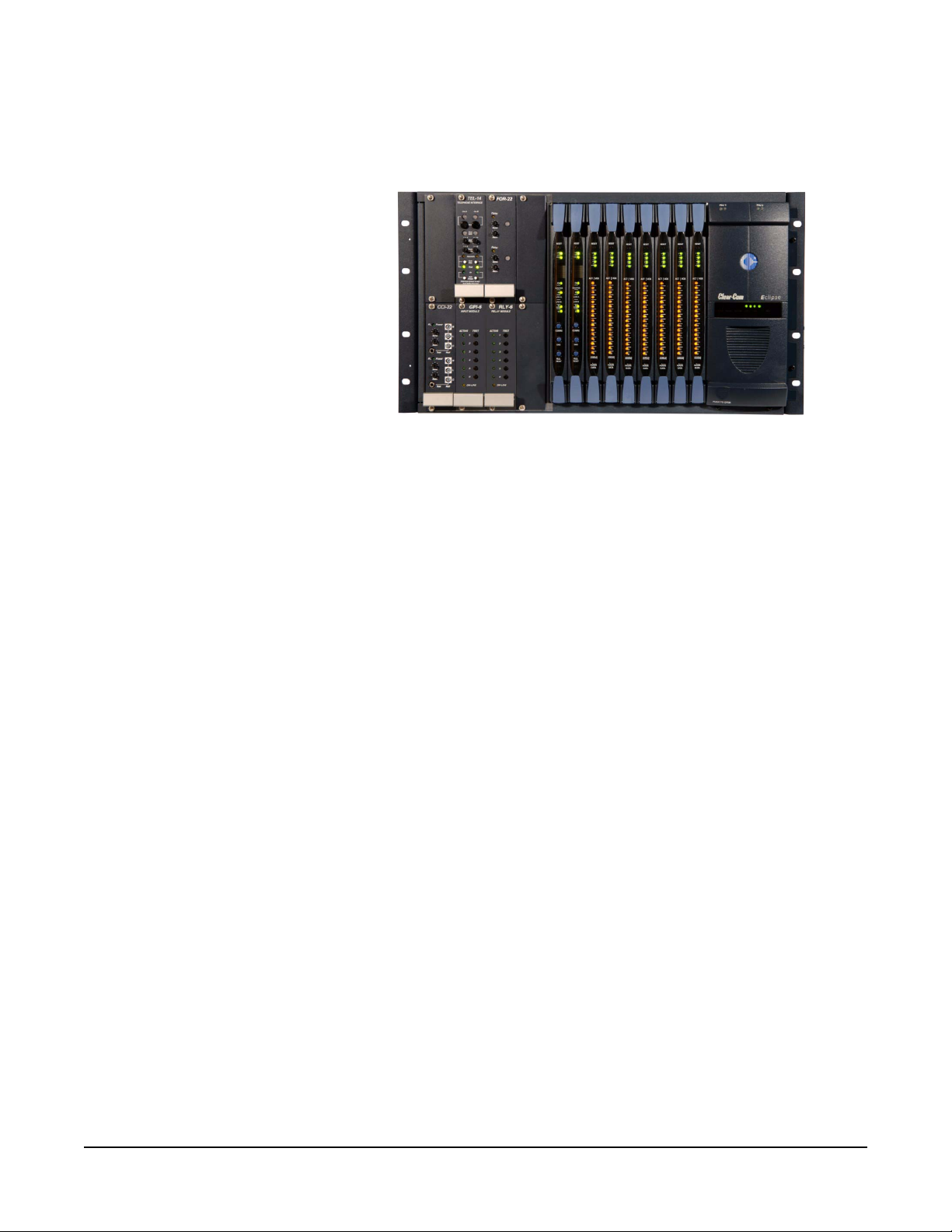
• The rear panel connectors which link the circuit cards to devices and
media such as intercom panels, interfaces, wireless equipment
and optical fiber.
Figure 1-1: The Eclipse Median Assembly
MATRIX CHASSIS
The matrix chassis is a metal rectangular box which measu res six rack
units high and 19-inches wide (26.9 cm x 48.3 cm). It has slots for 2
CPU cards, 7 circuit cards, 8 interface modules, and 2 power supplies.
RJ-45 and fiber-optic connectors are located on removable plates on
the rear of the chassis. These connect the circuit cards to intercom
devices and media such as panels, interfaces, 4-wire audio
equipment, wireless equipment and fiber-optic cables.
CIRCUIT CARDS
The matrix holds three types of circuit cards: CPU cards, port cards,
and interface cards. The cards slide vertically into the front of the
matrix and connect to the matrix’s backplane.
CPU Card
The CPU card is the master configuration card in the Eclipse Median
system. It provides the serial data and Ethernet connection to the
connected PC computer . Th e CPU card also coordinates the da ta flow
between the other cards in the system, allowing them to communicate
with each other. The computer memory chip which stores four
complete system configurations is located on the CPU card, so that a
selected configuration can be retrieved and activated directly from the
card.
Like the other cards in the system, the CPU card fits in the Eclipse
Median matrix. The card fits vertically in a six rack unit (6 RU) space
and connects to the matrix’s backplane.
Clear-Com
Eclipse Median Instruction Manual
1-3
Page 16

One CPU card is required for each Eclipse Median system. T wo cards
can be installed to provide redundancy in the case of outages or rep air
needs.
MVX-A16 Analog Port Card
An MVX-A16 analog port card controls the operation of panels and
interfaces connected to it. Panels and interfaces connect to the port
card through an RJ-45 connectors or “port” on the matrix’s rear panel.
Shielded category-5 cable attaches the panel or interface to the RJ-45
connector.
The MVX-A16 analog port card sends balanced audio and RS-422
data signals to connected audio equipment through 4-pair shielded
category-5 cable. The card connects up to 16 remote audio devices
such as intercom panels, interfaces, or 4-wire audio equipment to the
central matrix. Each audio device connected to a port card
communicates with all other audio devices in the system and with the
central matrix.
For intelligent linking, shielded category-5 cable is run from a port on
one Eclipse Median to a port on a second Eclipse Median to form a
trunkline connection.
E-FIB Fiber Interface
E-FIB fiber interfaces connect Eclipse matrices together to provide a
high speed, dual redundant link to transfer audio samples and data
between systems. These connections can be configured in various
ways to provide protection against the loss of a link or a node.
Each E-FIB fiber interface consists of a front card with various status
indicators and a rear card with two Duplex LC Terminated fiber optic
connectors (TXVRA and TXVRB).
E-QUE E1/T1 Interface
The E-QUE E1/T1 interface allows the Eclipse matrix connectivity to
FreeSpeak/CellCom antennas and FreeSpeak/CellCom antenna
splitters. Each E-QUE interface consists of a front card with a reset
button and various status indicators, and a rear card with eleven RJ45
ports giving eight standard ports, DECT sync in and out and a LAN
port for diagnostic use.
Each E-QUE front card has status LEDs for power, port activity and
LAN status. The port activity LEDs indicate whether there is a device
connected to an E1 port and that a connection has been established
between this port and the connected device.
1-4
The E-QUE interfaces must be fitted in the rightmost available slots
(furthest away from the CPU cards) on the Median and up to four
E-QUE interfaces can be fitted on a matrix.
Eclipse Median Instruction Manual
Clear-Com
Page 17

IVC-32 IP Interface
The IVC-32 interface allows the Eclipse matrix to connect to IP
enabled V-Series panels and Concert users via an IP network.
Each IVC-32 interface consists of a front card with a reset button and
various status indicators, and a rear card with eleven RJ45 ports giving
eight E1/T1 ports (not used), DECT sync in and out (not used) and a
LAN port for IP connectivity.
Each IVC-32 front card has status LEDs for power, port activity and
LAN status. The LAN indicators show whether there is a LAN
connection and the IP activity on the LAN port.
The IVC-32 cards must be fitted in the rightmost available slots
(furthest away from the CPU cards) on the Median and up to four
IVC-32 interfaces can be fitted to a matrix.
LMC-64 Interface
The LMC-64 interface allows the Eclipse matrix to provide Production
Maestro Pro clients with audio level metering of Party Lines
(Conferences) and 4-Wire ports via an IP network.
Each LMC-64 interface consists of a front card with a reset button and
various status indicators, and a rear card with eleven RJ45 ports giving
eight E1/T1 ports (not used), DECT sync in and out (not used) and a
LAN port for IP connectivity.
Each LMC-64 front card has status LEDs for power, port activity and
LAN status.
The LAN indicators show whether there is a LAN connection and the
IP activity on the LAN port.
The LMC-64 cards must be fitted in the rightmost available slots
(furthest away from the CPU cards) on the Median and up to four
LMC-64 interfaces can be fitted to a matrix.
Interface Modules
An interface module converts the 4-wire signals transmitted from the
matrix to other types of signals that communicate with such external
devices as telephones, camera intercoms, two-way radios, and so on.
In this way, non-4-wire devices can communicate with the matrix.
The Median houses any of the following interfaces modules:
• FOR-22. A two-channel, universal 4-wire interface with transformer
isolation, opto-isolation for logic input, and relay contacts for relay
out.
• CCI-22. A two-channel, isolated translator of 4-wire audio from the
matrix to two-wire intercom circuits, such as Clear-Com party line
products.
Clear-Com
Eclipse Median Instruction Manual
1-5
Page 18

• TEL-14. Allows two standard 2-wire POTS telephone lines to connect
to matrix ports.
• RLY-6. Provides six relays that can be wired for general purpose use
and controlled directly from the matrix.
• GPI-6. Provides a method to read external switch closures and
control voltages and translate them to operations in the matrix.
• AES-6. Provides a method to connect third party and digital devices
to the matrix.
Additional interfaces may be added to the Median via separate
interface module frames: the IMF-3, IMF-102, and DIF-102. See the
manual Interface Module Frames in the Eclipse manual set for more
information.
Note: The DIG-2 and VeNiX (ISDN) interface modules are not
compatible with the Median frame format.
POWER SUPPLIES
The Eclipse Median has two Euro Cassette power supply units that
can be easily installed or removed as needed. One power supply unit
can power an entire matrix; the second unit provides a backup in case
of failure or damage to the first unit.
In addition, the two supplies have separate IEC connectors to AC
mains, and are designed for completely automatic and transparent
changeover between supplies in the event of a power outage in one of
the AC mains circuits.
An over-temperature sensor is connected to both an audible failure
alarm and a warning light, allowing the system operator to diagnose
and correct any power anomalies while the system remains
operational.
MVX-A16 ANALOG PORTS
The matrix’s MVX-A16 interface RJ-45 connectors are called analog
ports. Shielded category-5 cable is used to connect an analog port to
intercom panels or interfaces.
ECLIPSE CONFIGURATION SOFTWARE (ECS)
The Eclipse Configuration Software (ECS) controls the operation of the
remotely connected audio devices by sending signals to the circuit
cards in the matrix, which then relay the signals to the remote audio
devices.
“Configurations”—which are the operating parameters of complete
system setups, can be created from the ECS computer. Up to four
complete system configurations can be stored in the computer’s
memory to retrieve and activate when needed. An unlimited numbe r of
1-6
Eclipse Median Instruction Manual
Clear-Com
Page 19

configurations can be stored on the ECS computer to be downloaded
to the matrix as required.
The Eclipse Configuration Software runs on fo ur versions of Win dows:
Windows XP professional, Windows Server 2003, Windows Vista and
Windows 7. When running ECS on the four Windows operating
systems, the client and server can run on separate machines
connected over a network.
Note: Windows Vista and Windows 7 are not fully supported for
ECS; please refer to the ECS manual (part 810299Z) for
further information.
Using ECS the system administrator can create point-to-point and
fixed group or party-line communications among the connected audio
devices, assign a “label” to each port/panel, inhibit or enable features
at any connected panel and configure connections between matrices.
The ECS system can be set up to run on a client/server model over a
network, allowing the system administrator to control the matrix
remotely.
INTERCOM AND ACCESSORY PANELS
All intercom panels connect to the central matrix via shielded
category-5 cable terminated with RJ-45 connectors. The shielded
category-5 cable connects to the matrix through the MVX-A16 analog
circuit card. The following Clear-Com intercom panels are compatible
with the Eclipse Median matrix system:
• V12LD, V24LD, V12PD, V24PD, V12RD, V24RD, V12LDD,
V12PDD, V12RDD, V12LDE, V12PDE and V12RDE V-Series
panels
• 4215E, 4224E, 4226E, 4294E, 4212E, 4222E, 4203E, 4206E, 4230E
and 4230VE 4000 Series II panels
• i-Station family, including expansion panels
• ICS-2003 intercom panels, including expansion panels
• ICS-52 and ICS-92 intercom panels, including expansion panels
• ICS-62 and ICS-102 intercom panels, including expansion panels
• ICS-1008 and ICS-1016 intercom panels, including expansion panels
• ICS-21, ICS-22 and ICS-24 panels have limited support
Each of these panels is described in its own manual. For a full
description of the operation, installation, and maintenance of a panel,
refer to that panel’s respective manual.
Clear-Com
Eclipse Median Instruction Manual
1-7
Page 20

INTERFACE MODULES
In addition to installing interfaces directly in the Median, you can install
interface modules in one of Clear-Com’s three interface frames: the
IMF-3, IMF-102, or DIF-102.
Interface modules convert the 4-wire signals of a central matrix port to
other types of signals that communicate with devices such as
telephones, camera intercoms, two-way radios, and so on. In this way
non-4-wire devices can communicate with the central matrix.
Each interface module has hardware connectors to connect to both the
central matrix and to the external device that communicates with the
central matrix. Most interface modules connect to the central matrix via
shielded category-5 cable terminated with RJ-45 connectors. The
DIG-2 digital interface module, however , connects to the central matr ix
via double-shielded 24 AWG conductor category-6 enhanced
(CAT-6E) STP cable.
The type of cable used to connect the interface module to the
non-4-wire device varies with the device. Each of these connections is
described more fully in the individual manual for each interface.
The following interface modules are compatible with the Eclipse
Median matrix:
• TEL-14 telephone interface module.
• CCI-22 dual party-line interface module.
• FOR-22 four-wire interface .
• GPI-6 general purpose inputs interface module.
• RLY-6 relay (general-purpose outputs) interface module.
• AES-6 digital interface module used with V-Series panels fitted with
the AES-3 option card and 4000 Series panels fitted with the
PDE4536 option card. It may also be used with AES-3 compliant
third party equipment.
• DIG-2 digital interface module (transparent to the system, configured
in ECS as the type of panel it is connected to). Only used for
V-Series panels fitted with the T-Adapter option card and ICSxx T
type panels.
Each of these interfaces is described in its own manual. For a full
description of the operation, installation, and maintenance of an
interface, refer to the individual manual for that interface.
1-8
Eclipse Median Instruction Manual
Clear-Com
Page 21
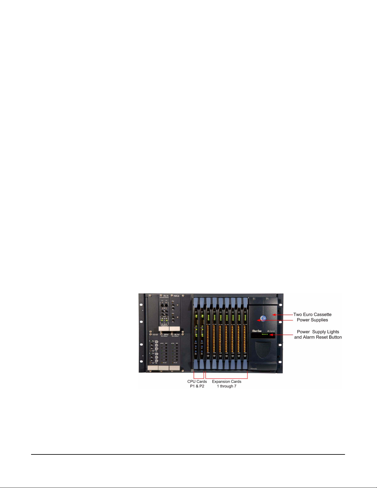
OPERATING AN
2
ECLIPSE MEDIAN
The Eclipse Median chassis houses the circuit cards, power supplies,
and connectors that form the central hardware of the system.
Measuring 19-inches wide and 6 rack units high (48.3 cm x 26.9 cm),
the matrix chassis installs in a standard equipment rack.
Various types of Eclipse Median circuit cards perform unique
functions. System cards control overall system operation, analog
interfaces control the operation of connected panels and interfaces
and communications interfaces allow communication with wireless
equipment, fiber optic links and IP networks.
Two Euro Casse tte power supp lies provide fail-safe r edundancy in th e
event of a component failure or an AC circuit outage. Front-panel lig hts
give information about the condition of the power supplies, allowing the
system operator to take preventative corrective action.
Each MVX-A16 interface connects to an individual panel on the back
of the Eclipse Median matrix. This panel holds the RJ-45 sockets for
connecting to intercom panels and interface modules.
The Eclipse Median matrix is completely modular, allowing cards,
power supplies, and connector panels to be added or removed to meet
operational needs.
USING THE ECLIPSE MEDIAN MATRIX
Figure 2-1: Front Panel of Eclipse Median
Clear-Com
Eclipse Median Instruction Manual
2-1
Page 22

Note: General Purpose
Outputs are also referred to
as “relays.”
Note: If the configuration
does not remain in memory
after you power off, please
see the first section in
Chapter 3, “Reconnecting the
CPU Card’s Backup Battery.”
CENTRAL PROCESSOR UNIT (CPU) CARD
The central processor unit (CPU) card holds the circuitry that allows
the system to connect to, and communicate with, the following
interfaces:
• An external personal computer
• Externally connected alarms
• Eight general-purpose inputs (GPIs)
• Eight general-purpose outputs (GPOs)
• Two separate local area network (LAN) connections for
Ethernet-based communication with a network
• An external interface that provides additional GPIs and GPOs
In addition, the card’s operational memory holds up to four complete
preassigned system configurations to access and activate either
directly from the CPU card or from the ECS application.
CREATING AND STORING SYSTEM CONFIGURATIONS
A “configuration” is a complete set of operating parameters for the
system which includes talk and listen paths for each connected
intercom panel. Depending on the interfaces installed, the
configuration can also include more sophisticated features such as
paging, call signaling, interrupt foldback (IFB), ISO, groups, automatic
DTMF dialing, routing, and many other features.
When an external computer is connected to the matrix the system
administrator can retrieve the current configuration information stored
in the CPU microprocessor’s memory (using the Eclipse Configuration
Software) and display the configuration on the computer’s screen.
The system administrator can then apply the current configuration,
modify it, or create a new configuration with the Eclipse Configuration
Software. If the system administrator creates more than one
configuration the unused configurations can be stored on the
computer’s hard disk or on CD-ROM to use later, allowing the system
to be reconfigured as required.
The CPU card itself will store up to four complete configurations in its
operational memory that can be applied either directly from the CPU
card or from the connected computer.
SETTING THE DEFAULT IP ADDRESS
The CPU card LAN ports can be reset to their default IP addresses by
pressing and holding the ‘ENG’ and ‘FULL RESET’ buttons on the
CPU front card and then pressing the ‘RESET’ button at the top and
then holding the ‘ENG’ and ‘FULL RESET’ buttons until the card
2-2
Eclipse Median Instruction Manual
Clear-Com
Page 23

resets. This will reset the LAN1 ethernet port to the factory default
address of 169.254.0.100 and all other ethernet ports to the 0.0.0.0
(blank) address and enable DHCP. If the system is fitted with two CPU
cards (master and slave) ensure that the default IP address procedure
is carried out on both cards but with only the card being reset plugged
in as detailed below.
• Remove the slave CPU card if present.
• Press and hold the ‘ENG’ and ‘FULL RESET’ front panel buttons
simultaneously then press the ‘RESET’ button on the master CPU
card.
• Replace the slave CPU card if there is one otherwise the
procedure is complete.
• Remove the master CPU card.
• Press and hold the ‘ENG’ and ‘FULL RESET’ front panel buttons
simultaneously then press the ‘RESET’ button on the slave CPU
card.
• Replace the master CPU card.
ETHERNET OPERATION
The CPU card ethernet ports are normally connected to a LAN and
used to communicate with clients such as ECS and Production
Maestro. The ethernet port functionality depends on the IP address
setup.
If an IP address of 0.0.0.0 is configured on the second ethernet port, it
will not be used for Tx or Rx. This is the default setup if the default IP
address is set as described above.
All matrix to matrix traffic is sent out on both ethernet ports. This
applies to both directed and broadcast packets. All matrix to matrix
traffic is also received on both ethernet port s. If the traf fic is transaction
related, the second (duplicate) message received is not consumed, but
simply dropped.
The matrices listen for client connections on both ethernet ports. Once
the connection is made it is added to the list of connections to service.
Broadcast type Tx data is duplicated out on each connection e.g. HCI
connection to the matrix from 3rd party applications.
The ECS Server makes a connection on either the main or backup
ethernet port of each system in the linked set. If both are up, this will
default to the primary port. In the event that connection is lost to the
currently active port on a matrix the ECS server will swap over to using
the other ethernet port. If this connection is lost only on one matrix in a
linked set, the others will not be affected.
Clear-Com
Eclipse Median Instruction Manual
Configuration Restrictions
2-3
Page 24

The network ID on the first ethernet port must be different to that of the
second port. The network ID is defined by the IP address and the
network mask for the port. For example a network address of
172.16.2.1 and a mask of 255.255.0.0 gives a network ID of 172.16.
Therefore in this scheme the second port could not have an IP address
starting with 172.16. If the network mask is extended to 255.255.255.0
the network ID becomes 172.16.2 so the second port could have an
address of 172.16.3.1 and a mask of 255.255.255.0 giving a network
ID of 172.16.3 for the second port.
If both ethernet ports are set up with the same network ID this
condition results in data loss on one or both of the ethernet ports.
Ethernet redundancy and the use of a default gateway is not
recommended. An IP address and gateway combination on an
ethernet port means that all Tx traffic to any address is possible on the
port. Traffic that actually match es the other ethernet port can therefore
be sent out on the wrong port.
FAIL-SAFE OPERATION
The CPU card’s non-volatile memory stores all information about the
current operating configuration and the three additional configurations,
allowing the system to restore itself automatically after a power failure,
after replacement of a port card, or after replacement of a panel.
An Eclipse Median system will operate with either one or two CPU
cards. When a second card is installed that card stores the four
configurations in its RAM as a backup to the main card. If the main
card is removed or becomes non-operational for any reason, the
system will automatically switch to the second card as backup.
OPERATING THE CPU CARD
The following sections describe the CPU card’s status lights and
controls, which are illustrated in Figure 2-2.
1
RESET BUTTON
Pressing the reset button causes the CPU card to stop its current
activity and to restart. The same configuration that was active before
the system was reset will be active after the system was reset.
During the reset, configuration information reloads to the card’s
operational memory from its non-volatile memory and the card starts
running again from the beginning.
Note: The reset button is slightly recessed from the front panel to
prevent it from being accidentally pressed. A tool such as a
bent paper clip is needed to press this button.
2-4
Eclipse Median Instruction Manual
Clear-Com
Page 25

2
POWER SUPPLY LIGHTS
+ 5-Volt Light
When lit, the “+5V” light indicates that the matrix’s +5-volt power
supply is actively supplying power to the CPU card.
+3.3-Volt Light
When lit, the “+3.3V” light indicates that the matrix’s +3.3-volt power
supply is actively supplying power to the CPU card.
3
DOT MATRIX LIGHTS
The rectangular array of lights just below the power-supply lights
displays a number (either 1, 2, 3, or 4) to indicate the currently
selected configuration. The Eclipse Configuration Software (ECS)
controls these lights. In addition these lights will indicate if the
following errors are detected at startup:
NVRAM Error
When the NVRAM is found to be corrupt at start up the config card will
output the string "CHECK BATTERY".
Non matching slave firmware
The eclipse system only supports master and slave backup between
two cards that are running the same version of firmware. In the case
when a non matching slave card firmware version is detected the
"NON-MATCHING SLAVE_FIRMWARE" banner is displayed by the
master CPU card.
The dot matrix lights will also display system information when the
“ENG” button is pressed on the master CPU card.
This is described below in the section on the “ENG” button.
Clear-Com
Eclipse Median Instruction Manual
2-5
Page 26
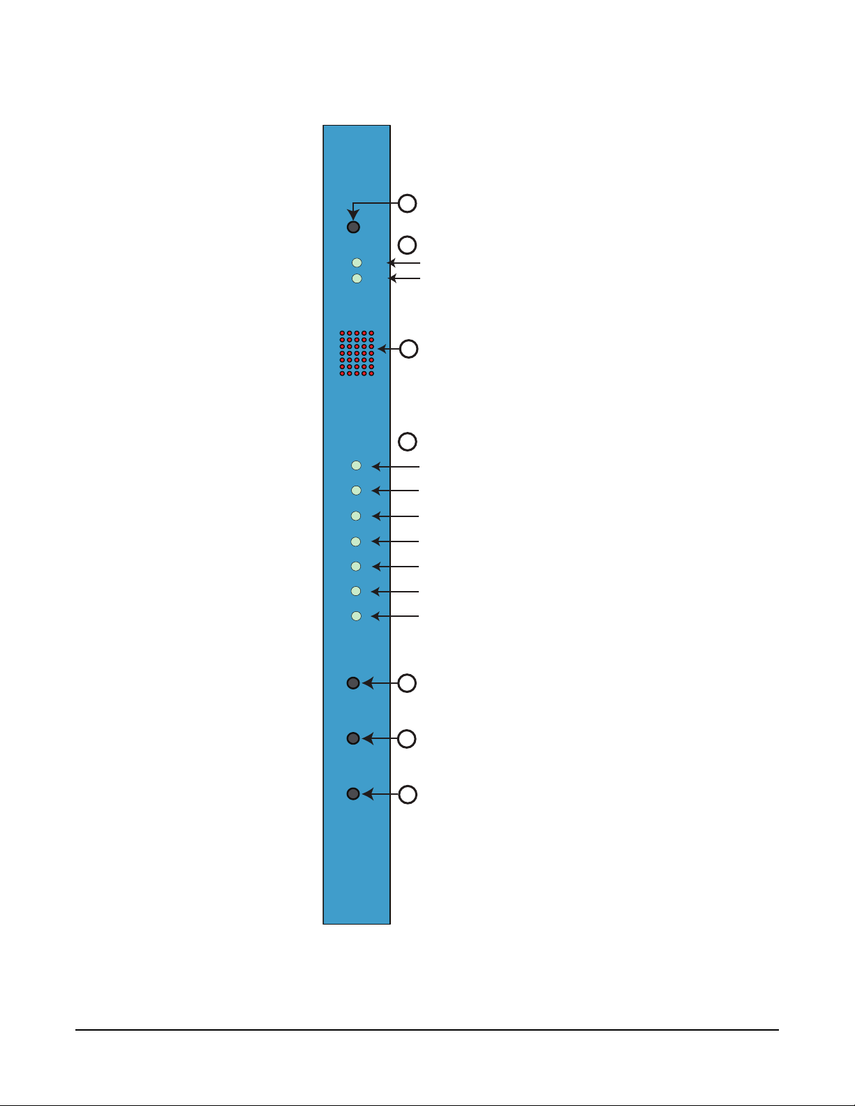
RESET BUTTON
1
RESET
OK
IPC
MASTER
LAN A
LAN B
IN SYNC
SI
+5V
+3.3V
2
POWER SUPPLY LIGHTS
When lit, +5-volt power supply is on
When lit, +3.3-volt power supply is on
DOT MATRIX LIGHTS
3
Displays the number of the currently selected software configuration
4
STATUS LIGHTS
When flashing, software is running
Blinks when two CPU cards are exchanging information
When lit, this CPU card is acting as master card
Blinks when LAN A is connected and running
Blinks when LAN B is connected and running
Blinks when multiple matrices are connected and synchronized
Reserved for future use
2-6
CONFIGURATION ("CONFIG") BUTTON
CONFIG
ENG
FULL
RESET
5
6
DEFAULT IP ADDRESS RESET BUTTON
Press with full reset and reset to set default IP address
FULL RESET BUTTON
7
When held through a reset cycle, results in a full system reset.
When pressed with the ENG button and reset button sets the
default IP address
Figure 2-2: CPU Card’s Front Panel Lights and Controls
Eclipse Median Instruction Manual
Clear-Com
Page 27

4
STATUS LIGHTS
OK Light
When flashing, the “OK” light indicates that the CPU card is
successfully communicating with the Eclipse Configuration Software
(ECS).
IPC (Interprocessor Communication) Light
The “interprocessor communication” (IPC) light only operates when
there are two CPU cards in the matrix. When lit, the light indicates that
the two CPU cards are exchanging information.
Master Light
An Eclipse Median system can have two CPU cards, although the
system will operate with only one. If the primary card becomes
unavailable for any reason, the second card can serve as backup while
the primary card is repaired or replaced.
The “master” light illuminates on whichever CPU card is currently
serving as master. If there is a backup CPU card in the matrix, its
“master” light will not illuminate if the primary card is acting as master.
LAN A Light
When a local area network (LAN) is connected to the matrix’s “LAN A”
port, the CPU card’s “LAN A” LED lights to indicate a conn ection to the
Eclipse matrix LAN A.
LAN B Light
When a second local area network is connected to the matrix’s “LAN
B” port, the CPU card’s “LAN B” LED lights to indicate a connection to
the Eclipse matrix LAN B.
Sync Light
When you connect multiple Eclipse matrices together, the “sync” light
illuminates to indicate that the matrices are connected and
synchronized.
SI Light
The “SI” light flashes to indicate communications activity.
Clear-Com
Eclipse Median Instruction Manual
2-7
Page 28

5
CONFIGURATION “CONFIG” BUTTON
The CPU card can hold four complete system configurations in its
operational memory. When the “CONFIG” button is pressed the
number of the currently active configuration (either 1, 2, 3, or 4)
appears in the dot-matrix display.
Each time the button is subsequently pressed the next configuration
number in the series appears in the dot-matrix display. The numbers
cycle forward until all of the choices have been displayed, then start
again at “1”.
When a non-active configuration’s number appears in the display, it
flashes to indicate its non-active status. Whe n an active configuration’ s
number (either 1,2, 3, or 4) appears in the display, it illuminates solidly
(without flashing) to indicate that it is the active configuration.
To select one of the four configurations from the CPU card
1. Repeatedly press the CONFIG button until the desired
configuration’s number (1,2,3, or 4) appears in the display.
2. When the desired number appears, press and hold the CONFIG
button until the display stops flashing. This should take about three
seconds.
The selected configuration then becomes the system’s active
operational configuration.
6
ENGINEERING “ENG” BUTTON
This button is used to reset the system to the default IP address
(169.254.0.100) with DHCP enabled and to display system information
on the LED dot matrix.
.To perform an IP address reset sequence:
1. Press and hold the ‘ENG’ and ‘FULL RESET’ front panel buttons
simultaneously.
2. Press the ‘RESET’ button.
If the system is fitted with two CPU cards (master and slave) ensure
that the default IP address procedure is carried out on both cards
but with only the card being reset plugged in as detailed below.
• Remove the slave CPU card if present.
• Press and hold the ‘ENG’ and ‘FULL RESET’ front panel buttons
simultaneously then press the ‘RESET’ button on the master CPU
card.
• Replace the slave CPU card if there is one otherwise the
procedure is complete.
• Remove the master CPU card
• Press and hold the ‘ENG’ and ‘FULL RESET’ front panel buttons
simultaneously then press the ‘RESET’ button on the slave CPU
card.
2-8
Eclipse Median Instruction Manual
Clear-Com
Page 29

• Replace the master CPU card
System Status
If the “ENG” button only on the master CPU is pressed the following
system information will be displayed on the LED matrix:
• Eclipse release - "V5.2" at 5.2
• Eclipse IP address - IP address of the LAN 1 port. Example output
- "IP 169.254.000.100". If this address isn't statically allocated, but
instead was allocated via DHCP server this will be pre-pended by
"DHCP ENABLED".
• System Number - This is only output if the rack is part of a linked
set. It is the system number of the node within the linked set.
Example output - "SYSTEM 3"
• Software version Number - Version number of the config card
software. Example output - "RACK 1.0.2.1"
• Hardware Serial number - Example output- "SERIAL 2251" in the
case where the HW serial number is 2251.
7
FULL RESET BUTTON
When a full reset is performed all cards in the matrix reset regardless
of any system preferences in the program software and non-volatile
memory is cleared.
To perform a full reset
1. Press and hold the card’s lower RESET button (the “full reset”
button).
2. Simultaneously press and release the card’s upper RESET button.
3. Continue holding the card’s lower RESET button for two seconds.
The card performs a full reset.
The same configuration that was active before you reset the system
will be active after you reset it.
When the cards and connected audio devices reset, they momentarily
stop their current activity and restart. During this process configuration
information is downloaded to the cards and remote audio devices from
the CPU card’s non-volatile RAM.
Note: Under normal operating conditions it is not necessary to
perform a full reset. Technical personnel might perform a
full reset if they believe that the CPU card is operating
incorrectly as a result of corruption of the microprocessor’s
internal data or instruction sequence.
Clear-Com
Eclipse Median Instruction Manual
2-9
Page 30

ANALOG PORT CARD DESCRIPTION
Analog port cards connect the central matrix to intercom panels and
interfaces. In a linked system, port cards connect trunk lines. The
analog card, designated the “MVX-A16”, supports normal audio feeds,
user panels, and trunk lines.
All cards contain a voice detection mechanism (“VOX”) that is
programmed from the ECS application. VOX detection allows a system
operator to know when the audio on a particular channel has exceeded
a threshold. This is particularly useful for channels that are inactive
periodically, so that an operator is visually cued when audio appears
on the line.
Each analog port card has two system status lights. A port card’s
FRAME DATA light illuminates to indicate the card’s successful
communication with the CPU card. A port card’s STATUS light
illuminates to indicate a failure in communication between the port card
and the CPU card. When all port cards are lined up in the matrix, the
system status lights form a horizontal row showing the overall state of
the system.
2-10
Eclipse Median Instruction Manual
Clear-Com
Page 31

ANALOG PORT CARD FRONT-PANEL LIGHTS AND CONTROLS
1
Reset Button
Pressing the reset button causes the card and all connected audio
devices to momentarily stop their current activity and to restart. The
card’s “frame data” light goes off when the reset start s and comes back
on when the reset is complete.
During the reset, configuration information downloads to the card and
its connected audio devices from the CPU card. If the entire system is
operating except for one port card, or one or more panels connected to
the card, press the reset button for that card only.
Note: The reset button is slightly recessed from the front panel to
prevent it from being accidentally pressed. A tool such as a
bent paper clip is requied to press this button.
2
Power Supply Lights
+12-Volt and -12-Volt Power Supply Lights
The matrix’s +12-volt and -12-volt power supplies provide electric
current to these two green lights. When lit, these lights indicate that the
matrix’s +12-volt and -12-volt power supplies are present and
supplying electric current to the card.
+5-Volt Power Supply Light
The matrix’s +5-volt power supply provides electric current to this
green light. When lit, the light indicates that the +5 supply is present
and supplying electric current to the card.
+3.3-Volt Power Supply Light
The matrix’s +3.3-volt power supply provides electric current to this
green light. When lit, the light indicates that the +3.3-volt supply is
present and supplying electric current to the card.
Clear-Com
Eclipse Median Instruction Manual
2-11
Page 32

1
RESET BUTTON
RESET
ACTIVE VOX
Frame
Status
Data
+12V
-12V
+5V
+3.3V
2
POWER SUPPLY LIGHTS
When lit, +12 V power supply is on
When lit, –12 V power supply is on
When lit, +5 V power supply is on
When lit, +3.3 V power supply is on
ACTIVE LIGHTS
3
16 yellow lights, one per port
1
2
3
4
5
6
7
8
9
10
11
12
13
14
15
16
When on, light indicates:
(1) There is a device connected to the port.
(2) Communications are running properly between the port and the card.
4
VOX LIGHTS
16 green lights, one per port
When on, light indicates:
(1) A VOX threshold for the port is programmed in the system software.
(2) Audio input on the port has exceeded the VOX threshold.
FRAME DATA LIGHT
5
The green "frame data" light illuminates to indicate successful communication
between the port card and the CPU card.
2-12
6
STATUS LIGHT
The red "status" light illuminates to indicate a failure in communication
between the port card and the CPU card.
Figure 2-3: Analog Port Card Lights and Controls
Eclipse Median Instruction Manual
Clear-Com
Page 33

Active Lights
3
When lit, an “active” light indicates successful communication between
the port card and a connected remote device such as an intercom
panel or interface.
Each of the port card’s 16 yellow “active” lights corresponds to one of
16 rear-panel connectors or “ports” to which remote aud io devices can
be connected.
VOX Lights
4
When lit a “VOX” light indicates that the audio level on a connected
remote device, such as an intercom panel or interface , has exceeded a
preset threshold. The threshold audio level is set through the ECS
application.
Each of the port card’s 16 green “VOX” lights corresponds to one of 16
rear-panel connectors or “ports” to which audio devices (intercom
panels or interfaces) can be connected.
5
Frame Data Light
The green “frame data” light illuminates to indicate successful
communication between the port card and the CPU card.
Status Light
6
The red “status” light illuminates to indicate a failure in communication
between the port card and the CPU card.
INTERFACE CARD DESCRIPTION
The following interfaces can be installed in the Median:
• FOR-22. A two-channel, universal 4-wire interface with transformer
isolation, opto-isolation for logic input, and relay contacts for relay
out.
• CCI-22. A two-channel, isolated translator of 4-wire audio from the
matrix to two-wire intercom circuits, such as Clear-Com party line
products.
• TEL-14. Allows two standard 2-wire POTS telephone lines to connect
to matrix ports.
• RLY-6. Provides six relays that can be wired for general purpose use
and controlled directly from the matrix.
Clear-Com
Eclipse Median Instruction Manual
• GPI-6. Provides a method to read external switch closures and
control voltages and translate them to operations in the matrix.
2-13
Page 34

• AES-6. Provides an interface for third party devices and digital
panels.
Each of these interfaces has its own individual manual in the Eclipse
set of manuals. Refer to an interface’s individual manual for more
information on operating, installing, or maintaining it.
Note: Unlike interfaces installed in a separate interface frame, the
interfaces installed in the Median are powered by the same
onboard power supply that also powers the CPU card and
port cards.
POWER SUPPLY DESCRIPTION
Eclipse Median has two Euro Cassette power supply units can be
easily installed or removed as needed. One power supply unit can
power an entire matrix; the second unit provides a backup in case of
an equipment failure.
In addition, the two supplies have separate IEC connectors to AC
mains power, and are designed for completely automatic and
transparent changeover between supplies in the event of an out age on
one of the AC mains circuits. For this feature to work, each power
supply should be connected to a different AC mains branch.
If the temperature inside the Eclipse matrix exceeds a threshold, both
an audible alarm and a warning light switch on, allowing the system
operator to diagnose and correct power anomalies while the system
remains in operation.
Warning: Eclipse Median matrices may be fitted with HITRON
(part 740134Z) or Power-One (part 720379Z) power
supply units depending on the date of manufacture.
The different types of power supply units must not be
mixed in an Median matrix; if one of the pair of power
supplies is replaced it must be replaced with the same
type of power supply unit. If this is not possible both
power supplies must be replaced with power supply
units of the same type.
Power-One power supplies are identified by the part
number on the from of the unit; HITRON units do not
have a part number on the front of the unit.
Each cassette has two status lights located on the power supply unit in
the upper left corner . The green light st ays on continuously to indicate
that the unit is receiving appropriate power. The amber (HITRON unit)
or red (Power-One unit) light goes on when a DC output or AC input
falls too low.
2-14
DIAGNOSING POWER SUPPLY PROBLEMS
Figure 2-4 illustrates the front panel alarm lights, power supply lights,
and reset button. An alarm source triggers the main alarm light and
Eclipse Median Instruction Manual
Clear-Com
Page 35

also one of the additional six red alarm lights, allowing the system
operator to identify or correct alarm conditions before they affect the
operation of the matrix.
Each of the four green power supply lights stays on continuously to
show that the power supplies are receiving sufficient AC current. When
one of these lights switches off, the power supplies need to be
replaced or repaired.
Under normal operating conditions, the red front-panel alarm lights
stay off, while the green power supply lights stay on continuously.
Euro Cassette
Alarm Lights
Alarm Lights
Main Alarm Light
External Alarm (EXT ALARM) Light
Temp Alarm Light
Fan-Fail Alarm Light
PSU1 Fail Light
PSU2 Fail Light
Fan-On Alarm Light
Euro Cassette
Power Supply 1
Euro Cassette
Power Supply 2
Power Supply LIghts
+12 Volt Light
+ 5 Volt Light
+3.3 Volt Light
--12 Volt Light
Alarm Reset Button
Clear-Com
Eclipse Median Instruction Manual
Figure 2-4: Power supply module’s front door
CONDITIONS THAT CAUSE AN ALARM
The following conditions trigger an alarm:
• If any of the voltages produced by the first power supply unit fall
below normal levels.
• If any of the voltages produced by the second power supply unit fall
below normal levels.
2-15
Page 36

• If an internal matrix alarm condition activates a matrix relay to turn on
an external alarm.
• If the active CPU card exceeds a temperature threshold.
• If either of the CPU cards is removed from the matrix.
• If either of the matrix’s two cooling fans stop operating.
• If the temperature inside the Eclipse matrix exceeds a set threshold.
MAIN ALARM LIGHT
An alarm condition triggers the following events:
• The red main alarm light flashes.
• The matrix’s internal alarm buzzer sounds.
• Any installed alarm relay outputs switch to active (the normally open
contact closes and the normally closed contact opens). When the
alarm relay activates, it can cause an externally connected device
like a light or buzzer to switch on.
• One of the six auxiliary red alarm lights may go on to more precisely
indicate the source of the alarm condition. These lights are
discussed in further detail later in this section.
ALARM RESET BUTTON
When you press the alarm reset button, the following events take
place, even if the alarm condition has not been corrected:
• The internal audible alarm buzzer stops buzzing.
• Any wired relay contacts return to their inactive state. If these relays
are connected to external alarm lights or alarm buzzers, those
lights or buzzers shut off.
If the original alarm condition still exists, the red main alarm light on the
matrix’s front panel continues to flash. The red main alarm light only
stops flashing when all original sources triggering the alarm are
corrected.
If a new alarm condition or conditions occur before the original alarm
conditions are corrected, the internal buzzer and relay contact s will not
reactivate. They will only reactivate after all original alarm conditions
are corrected.
2-16
Eclipse Median Instruction Manual
Clear-Com
Page 37

AUXILIARY ALARM LIGHTS
When an alarm condition occurs, any of the six auxiliary alarm lights
may switch on, in addition to the main alarm light, to help diagnose the
alarm condition. The following sections describe the six auxiliary alarm
lights.
External Alarm (“Ext Alarm”)
The “external” alarm (labelled “EXT ALARM”) light switches on to
indicate that an alarm condition has triggered the built-in relay outputs
to turn on any externally installed alarms such as lights or bells. You
connect the external alarm to the matrix through the 9-pin D-type
connector on the matrix’s rear panel labeled “Alarm I/O”.
Temp Alarm
The red “temp” alarm light switches on to indicate one or both of the
following:
• The active CPU card has detected a temperature in the matrix above
a threshold.
• One of two CPU cards has been removed from the matrix.
Note that this feature only operates if there are two CPU cards
installed in the matrix. If there is only one CPU card, the Temp
alarm light does not switch on if the card is removed.
Fan-Fail Alarm
The red fan-fail alarm light illuminates when either fan in the
power-supply module stops rotating correctly.
PSU1 Fail
When the first power supply unit is operating correctly, the red PSU1
light stays off, while the four green power supply lights (+12V, +5V,
+3.3V, -12V) stay on continuously.
If a DC output or AC input to the first power supply drops too low, the
red PSU1 light switches on. The amber (HITRON) or red (Power-One)
light on the power supply unit itself also switches on to indicate the
same condition. One of the green power supply lights may then switch
off to help indicate the source of the trouble.
Note that the PSU1 fail light only works if the first power supply is
plugged into the matrix’s midplane from inside the matrix.
Note: A temperature sensor inside the power supply senses if the
power supply overheats, and switches on the second
matrix cooling fan. The red “Temp” light switches on to
indicate that the active CPU card, not a power supply, has
overheated.
Clear-Com
Eclipse Median Instruction Manual
2-17
Page 38

PSU2 Fail
You can precisely locate a
port with its row and column
numbers as shown in Figure
2-7.
When the second power supply unit is operating correctly, the red
PSU2 light is off, while the four green power supply lights (+12V, +5V,
+3.3V, -12V) are on continuously.
When a DC output or AC input to the second power supply drops too
low, the red PSU2 light switches on. The amber (HITRON) or red
(Power-One) light on the power supply unit itself also switches on to
indicate the same condition. One of the green power supply lights may
then switch off to help indicate the source of the trouble.
Note that the PSU2 fail light only works if the second power supply is
plugged into the matrix’s midplane from inside the matrix.
Note: A temperature sensor inside the power supply senses if the
power supply overheats, and switches on the second matrix
cooling fan. The red “Temp” light switches on to indicate
that the active CPU card, not a power supply, has
overheated.
Fan-On Indicator
Two fans deliver forced air cooling to the matrix’s power supplies. The
primary fan runs continuously. If a temperature exceeding a threshold
is detected in a power supply and extra cooling is required, a second
fan switches on to increase the air flow. The “fan-on” alarm light
illuminates red to indicate that the second fan is on.
POWER SUPPLY LIGHTS
The green power-supply lights illuminate to indicate that the power
supplies are receiving +12 V, –12 V, +5 V, and 3.3 V power.
2-18
Eclipse Median Instruction Manual
Clear-Com
Page 39

CONNECTING THE MATRIX
The Eclipse Median connects to devices such as the configuration
computer , panels, interface s, and other matrices through it s rear-p anel
hardware connectors, often called “ports”. These connectors are
housed in modular removable panels. Each panel is associated with a
corresponding front-panel circuit card.
Ports CPU
Interfaces
Clear-Com
Eclipse Median Instruction Manual
Figure 2-5: Eclipse Median Rear Connector panels
There are six types of rear-connector panels:
• The CPU-card rear panel holds the various connectors associated
with the CPU card, such as the RS-232 connector for the
configuration computer. The CPU-card rear connectors are
discussed in the next section, “Connecting the CPU Card”.
• An analog port-card rear panel holds the sixteen RJ-45 connectors
associated with its corresponding front-panel port card. Remote
intercom panels and interfaces connect to the matrix through this
rear-connector panel.
• A E-FIB fiber card provides two ports to connect fiber network cables.
2-19
Page 40

• An E-QUE card provides eight RJ-45 ports for connection to wireless
equipment and three RJ-45 ports for DECT sync and LAN
connections.
• An IVC-32 card provides a RJ-45 port for connection to an IP
network. No other ports are used.
• An LMC-64 card provides a RJ-45 port for connection to an IP
network. No other ports are used.
• Blank panels covers unused slots in the matrix.
CONNECTING THE CPU CARD
The rear-connector panel associated with the CPU card holds seven
connectors, as illustrated in Figure 2-6. The following sections
describe each connector. The Inst allation Chapter of this ma nual gives
pin assignments for each connector.
Note: A matrix only requires one rear-panel CPU card, because
whichever of the two front-installed CPU cards is acting as
master will work in conjunction with this card. All other
cards, however, require their own rear-connector panel.
2-20
Eclipse Median Instruction Manual
Clear-Com
Page 41

GPI/RLY Interface Connector
1
(RJ-45)
RS-232 Connector (male 9-pin D-type)
General Purpose Outputs Connector
(male 25-pin D-type)
Figure 2-6: CPU Card’s Rear-Connector Panel
1
CONNECTING TO A GPI-RLY INTERFACE
2
Alarm I/O Connector
3
(female 9-pin D-type)
4
General Purpose Inputs Connector
5
(female 25-pin D-type)
6
LAN 1 Connector (RJ-45)
LAN 2 Connector (RJ-45)
7
Clear-Com
Eclipse Median Instruction Manual
The RJ-45 socket labeled “GPI/RLY Interfa ce” con nects the CPU card
to a GPI-6 or RLY-6 card. The GPI-6 provides six general-purpose
opto-isolated logic inputs. The RLY-6 card provides six single-pole,
double-throw relay outputs.
Both card types mount in either an IMF-3 interface frame or an
IMF-102 interface frame. You can operate up to ten GPI-6 or RLY-6
cards at one time from the matrix by daisy-chaining the cards together.
Each card has an IN and an OUT connector for this purpose.
The RLY-6 and GPI-6 cards connect to the GPI/RLY interface
connector using shielded category-5 cable. For more information about
the GPI-6 and RLY-6 cards, consul t their respective manuals in the
Eclipse Median manual set.
2-21
Page 42

Note: If this port is used a ferrite must be added to the socket end
of each cable. A suitable ferrite is Würth Electronik part:
74271132.
2
RS-232 CONNECTOR
The female 9-pin D-type socket labeled “RS-232” connects the CPU
card to an external computer.
Note: A shielded cable should be used.
ALARM I/O CONNECTOR
3
The female 9-pin D-type socket labeled “Alarm I/O” connects the
Eclipse matrix to an external alarm indicator, such as a light or buzzer
and/or to an external alarm source.
Note: A shielded cable should be used.
CONNECTING TO GENERAL-PURPOSE OUT-
4
PUTS (“GP OUT”)
The male 25-pin D-type socket labeled “GP OUT” connects the CPU
card to eight general purpose outputs (GPOs). General-purpose
outputs are single-pole double-throw relays with contact ratings of 30
VDC (volts direct current) at 1 ampere.
A general purpose output or “relay” is a switch that is controlled
remotely. The relay is programmed in ECS to close a contact
whenever an intercom panel key is pressed. When the contact is
closed, it completes an electronic circuit’s signal path so that a remote
device, such as a light, is powered.
A GPO can be programmed to mute a speaker, to turn on an applau se
light, to turn on a door lock, or to perform a variety of other functions.
For example, to get the attention of a panel operator working in a
high-noise environment such as a control booth, a relay can be
prgrammed to switch on a light at operator panel each time an
incoming call is received, to ensure that the call is not missed.
Note: If the GP-OUT port is used on a Median matrix fitted with
HITRON power supplies (part 740134Z) the following filter
must be fitted between the PROC-RCC socket and the cable:
CINCH FA-25PS/1-LF 25W D-type in-line 1000pF filter
(UK supplier: Farnell 111-4108)
If the Median matrix is equipped with Power-One power
supplies (part 720379Z) this filter should not be fitted. If this
filter is already fitted to an Median matrix and the power
2-22
Eclipse Median Instruction Manual
Clear-Com
Page 43

supplies are changed to Power-One units the filter must be
removed before the matrix is powered up
Note: A shielded cable should be used.
5
GENERAL-PURPOSE INPUTS (“GP IN”)
The female 25-pin D-type socket labeled “GP IN” connect s the Eclip se
Median CPU card to eight general purpose inputs (GPIs).
An external device such as an external foot switch, a panel-mounted
switch, or the logic output of some other device can be connected to
the “GP IN” connector. When the external logic device is activated, it
sends a control signal into the matrix to perform one of several preset
functions, such as turning an intercom panel’s microphone on or off,
muting a microphone’s output, or turning a panel’s speaker off. The
function to perform and the panel upon which it is performed is
configured using ECS.
Note: A shielded cable should be used.
LOCAL AREA NETWORK 1 PORT (“LAN 1”)
6
The RJ-45 socket labeled “LAN 1” connects a local area network
(LAN) to the CPU card through a standard Ethernet connection. The
green LED indicates the port is connected and the amber LED
indicates activity.
Note: If this port is used a ferrite must be added to the socket end
of each cable. A suitable ferrite is Würth Electronik part:
74271132.
Note: A shielded CAT-5 cable should be used.
LOCAL AREA NETWORK 2 PORT (“LAN 2”)
7
The RJ-45 socket labeled “LAN 2” connects a second local area
network (LAN) to the CPU card through a standard Ethernet
connection. The green LED indicates the port is connected and the
amber LED indicates activity.
Note: If this port is used a ferrite must be added to the socket end
of each cable. A suitable ferrite is Würth Electronik part:
74271132.
Note: A shielded CAT-5 cable should be used.
Clear-Com
Eclipse Median Instruction Manual
CONNECTING PORT CARDS
Each rear-connector panel associated with an MVX-A16 interface
holds the sixteen RJ-45 connectors that connect the matrix to intercom
2-23
Page 44

Rows
7-1
7-2
7-3
7-4
7-5
7-6
7-7
7-8
7-9
7-10
7-11
7-12
7-13
7-14
7-15
7-16
6-1 5-1 4-1 3-1 2-1 1-1
panels and interfaces. Each front-installed MVX-A16 port card requires
a corresponding rear-connector panel. Blank panels cover unused
slots.
Each port on the matrix can be located and identified by using the
rear-panel numbering grid.
• Port rows are numbered 1 through 16.
• Ports columns are numbered 1 through 7.
• CPU card columns are numbered P1 and P2. (One rear panel
operates with either of the currently active CPU cards).
A port can be identified precisely by identifying its card number and
port number on the card. For example, the ports on the first card are
designated 1-1, 1-2, 1-3, 1-4, and so on; the ports on the second
card are designated 2-1, 2-2, 2-3, 2-4, and so on.
Each rear-connector panel associated with a fiber interface holds
two fiber connection ports. Each front-installed E-FIB card requires
a corresponding rear-connector panel.
Columns
7 6 5 4 3 2 1
2-24
1
2
3
4
5
6
7
8
9
10
11
12
13
14
15
16
6-1 5-1 4-1 3-1 2-1 1-1
7-1
7-2
7-3
7-4
7-5
7-6
7-7
7-8
7-9
7-10
7-11
7-12
7-13
7-14
7-15
7-16
Each rear connector panel associated with an E-QUE interface holds
eleven RJ-45 ports:
• Eight ports for connection to wireless equipment.
Figure 2-7: Eclipse Median Rear-Panel Port Numbering Grid
Eclipse Median Instruction Manual
Clear-Com
Page 45

• Two ports for DECT sync.
• One port for LAN interface.
Each rear connector panel associated with an IVC-32 interface holds
eleven RJ-45 ports:
• Eight ports for connection to E1/T1 equipment (not used).
• Two ports for DECT sync (not used).
• One port for LAN interface.
Each rear connector panel associated with an LMC-64 interface holds
eleven RJ-45 ports:
• Eight ports for connection to E1/T1 equipment (not used).
• Two ports for DECT sync (not used).
• One port for LAN interface used for broadcasting audio levels to
Production Maestro Pro clients.
Each rear connector panel associated with an E-FIB interface holds
two fiber ports (TXVRA and TXVRB).
Clear-Com
Eclipse Median Instruction Manual
2-25
Page 46

2-26
Eclipse Median Instruction Manual
Clear-Com
Page 47

ECLIPSE FIBER
3
LINKING
FIBER INTERFACE DESCRIPTION
E-FIB fiber interfaces connect Eclipse matrices together to provide a
high speed, dual redundant link to transfer audio samples and data
between systems. These connections can be configured in various
ways to provide protection against the loss of a link or a node.
Each fiber interface consists of a front card with various status
indicators and a rear card with two Duplex LC Terminated fiber optic
connectors (TXVRA and TXVRB). The fiber interfaces use 9/125µ
Single Mode fiber optic cables. The standard maximum node length is
10km but other distances are available to special order. For further
details please refer to the Technical Specifications in this manual.
Each fiber optic front card has a reset button, status LEDs for power,
processor function, card status, link status and link activity. The link
status and activity LEDs indicate whether there is activity on a link,
whether the card is transmitting on a link and the error state of a link.
Normally fiber interfaces should be fitted in slots 6 and/or 7 of an
Median matrix. If fiber interfaces are fitted to any matrix in a linked
system all the linked matrices must be reset to ensure that all matrices
correctly recognize the new hardware.
Clear-Com
Eclipse Median Instruction Manual
E-FIB FRONT-PANEL LIGHTS AND CONTROLS
1
Reset Button
Pressing the reset button causes the card and all links to momentarily
stop their current activity and to restart. The card’s “frame data” light
goes off when the reset starts and comes back on when the reset is
complete.
During the reset, configuration information downloads to the card and
its connected matrices from the CPU card. If the entire system is
operating except for one fiber card press the reset button for that card
only.
Note: The reset button is slightly recessed from the front panel to
prevent it from being accidentally pressed. A tool such as
a bent paper clip is needed to press this button.
3-1
Page 48

2
Power Supply & Status Lights
+3.3-Volt Power Supply LED
The matrix’s +3.3-volt power supply provides electric current to this
green light. When lit, the light indicates that the +3.3-volt supply is
present and supplying electric current to the card.
Processor LED
When lit the LED indicates that the fiber card on-board processor is
running
Front Card LED
When lit indicates that the front card in functioning normally.
Rear Card LED
When lit indicates that the rear card is functioning normally.
3-2
Eclipse Median Instruction Manual
Clear-Com
Page 49

1
RESET BUTTON
Link active
Indicates link
error
Link active
Indicates link
error
RESET
TXVRA
ACT
ERR
TXVRB
ACT
ERR
+3.3V
PROC
FRONT
REAR
LINK
TXVR
LINK
TXVR
2
POWER SUPPLY & STATUS LIGHTS
When lit, +3.3 V power supply is on
When lit, the processor is running
When lit the front card is functioning
When lit the rear card is functioning
3
LINK A STATUS LIGHTS
When lit the link is established
Indicates data transmit
4
LINK B STATUS LIGHTS
When lit the link is established
Indicates data transmit
Clear-Com
Eclipse Median Instruction Manual
STATUS LIGHT
5
Status
When flashing, this light indicates
card status
Frame
Data
FRAME DATA LIGHT
When flashing, this light indicates
6
that information is passing between
the CPU card and this card
Figure 3-1: Front Fiber Card
3-3
Page 50

Primary Link Status LEDs
3
These LEDs indicate the status and functioning of the primary (A) fiber
optic link.
Link LED
This LED indicates whether a link has been established on the primary
fiber optic circuit (transceiver A). When illuminated a link is present.
TXVR LED
This LED indicates when data is being transmitted on the primary
circuit. It is illuminated when data is present on the circuit.
ACT LED
This LED is lit if the primary fiber optic circuit is active.
ERR LED
This LED will be illuminated if an error condition is detected on the
primary fiber optic circuit.
Secondary Link Status LEDs
4
These LEDs indicate the status and functioning of the secondary (B)
fiber optic link.
Link LED
This LED indicates whether a link has been established on the
secondary fiber optic circuit (transceiver B). When illuminated a link is
present.
TXVR LED
This LED indicates when data is being transmitted on the secondary
circuit. It is illuminated when data is present on the circuit.
ACT LED
This LED is lit if the secondary fiber optic circuit is active.
ERR LED
This LED will be illuminated if an error condition is detected on the
secondary fiber optic circuit.
5
Status LED
The green “frame data” LED illuminates to indicate successful
communication between the fiber master card and the CPU card.
3-4
Eclipse Median Instruction Manual
Clear-Com
Page 51

Frame Data LED
6
The red “status” light illuminates to indicate a failure in communication
between the fiber card and the CPU card.
FIBER CARD REAR PANEL LIGHTS AND CONNECTIONS
The fiber card rear card contains a single power supply indicator LED
and two fiber connectors.
Class 1 Laser Product
Transceiver
Lasers
RX
TX
+3.3V
TXVRB
TXVRA
When lit, +3.3 V power supply is on
Secondary Fiber Port
Primary Fiber Port
NOTE
Primary and Secondary
Fiber ports are reversed
with respect to the front
panel indicators.
Take care when unplugging
the cables to unplug the
correct cable.
Clear-Com
Eclipse Median Instruction Manual
Figure 3-2: Rear Fiber Card
3-5
Page 52

Each fiber card has two fiber transceivers with Duplex LC type
connectors. The TX1/RX1 connector is used for the main ring and the
TX2/RX2 connector is used for the secondary ring. Single mode
9/125µ fiber optic cable should be used for connections and the
matrices should be wired up with the system with the lowest I/P
address being system 1.
The fiber optic cable for the primary and secondary circuits are
plugged into the appropriate ports. An example showing three
systems configured with a primary and secondary ring is shown in
Figure 3-6.
3-6
Figure 3-3: Example Fiber Ring Setup
Eye Safety
This laser based single mode transceiver is a Class 1 product. It
complies with IEC 60825-1/A2:2001 and FDA performance
standards for laser product s (21 CFR 1040.10 and 1040.11) except
for deviations pursuant to Laser Notice 50, dated July 26, 2001.
Note: The order of the fiber optic cable connections is reversed
between the front and rear panels. On the front panel the
Eclipse Median Instruction Manual
Clear-Com
Page 53

primary connection is the upper set of indicators but on the
rear panel it is the lower connector. Similarly the sec ondary
connection is the lower set of indicators on the front panel
but the upper connector on the rear panel. Care should be
taken when connecting or disconnecting the cables to
ensure that they are connected correctly and not reversed.
Note: Normally a protective plug is fitted to the fiber connector
sockets to protect them from damage or the entry of foreign
materials. These should only be removed in order to fit the
fiber optic cable and replaced if the cable is unplugged.
CONFIGURING A FIBER OPTIC CONNECTION
There are a number of ways that optical connections can be made
between systems depending on the level of redundancy required.
When a break occurs in the fiber ring, a solid red status light will be
shown at the fiber card downstream from the break and the link status
LEDs may show amber. Other fiber cards will intermittently show red,
as the ring attempts to recover. If the system layout is displayed by
ECS the faulty links are shown in red.
In order to diagnose faults or switch between primary and secondary
rings or between primary and backup fiber linking cards the My
Systems in ECS must be used. Ensure that the current configuration
is open and click on ‘Live Status’ in the My Systems toolbar to display
the current system state.
This will allow the operator to intervene to alter the system
configuration as required. For details of ECS please refer to the ECS
instruction manual (part number 810299).
SIMPLEX FIBER CABLING
Single Card Set Redundancy
In this case each Matrix Frame contains one fiber-optic Linking card
set . This is shown as in Figure 3-4. This approach still affords fiber
connection redundancy since each rear card houses two fiber-optic
transceivers.
In the absence of an Uninterrupted Power Supply (UPS) this
configuration will not protect against loss of the node or Matrix Frame
itself.
Clear-Com
Eclipse Median Instruction Manual
3-7
Page 54

Figure 3-4: Ring Topology Single Card Set Redundancy
Loss of Single Fiber Connection
If a single fiber connection is lost on one ring and the other ring is intact
then the active ring always attempts to heal itself by reversing the
direction of data flow to bypass the failed connection. If the extent of
the failure is such that the active ring is unable to heal itself then the
system will switch to the secondary ring.
The self healing mechanism is performed automatically by the Fiber
Linking Card whereas the switch-over between redundant cards and
rings requires software or operator intervention. Switching to the
secondary ring will cause audio breaks or disturbances and tempora ry
loss of crosspoint data.
If a single fiber connection is lost on both rings the nodes adjacent to
the failures will loop-back their connections to the failed cables healing
the rings and the most intact ring will be used.
The Eclipse Configuration Software (ECS) will report any failures in the
fiber connection system.
3-8
Eclipse Median Instruction Manual
Clear-Com
Page 55

Loss of a Single Node
If a node is lost on the ring the nodes adjacent to the failed node will
loop-back their connections to the failed node healing the ring using
the working remains of the ring. The configuration software (ECS) will
report the failure.
This applies to the situation where the fiber card itself has failed rathe r
than the matrix.
Loss of Two Fiber Connections
If two adjacent fiber connections are lost on the ring this will be
handled as for the loss of a single node where the nodes adjacent to
the failed node will loop-back their connections to the failed node
healing the ring. The configuration software will report the failure
correctly as two failed cables . If two non-adjacent fiber connections
are lost on the ring the nodes adjacent to the failures will loop-back
their connections to the failed cables healing the ring into 2 separate
smaller rings. The configuration software will report the failure.
Note that in this instance the two sub-rings will be dependent on their
Ethernet connections for configuration and data transmission but there
will be no audio path between them.
Loss of Two Nodes
If two adjacent nodes are lost on the ring this will be handled as for the
loss of a single node where the nodes adjacent to the failed node will
loop-back their connections to the failed nodes healing the ring. The
configuration software will report the failure correctly as two failed
nodes . If two non-adjacent nodes are lost on the ring the nodes
adjacent to the failures will loop-back their connections to the failed
nodes healing the ring into 2 separate smaller rings. T he configuration
software will report the failure. Note that in this instance the two
sub-rings will be dependent on their Ethernet connections for
configuration and data transmission but there will be no audio path
between them.
DUAL CARD SET REDUNDANCY
This is shown as in Figure 3-5 with both "Card set A" and "Card set B"
fitted in each node of the ring. In this case each Matrix Frame contains
two Fiber-optic Linking card sets. This approach affords full
redundancy, offering protection against component failure within a
single Fiber-optic Linking Card Set. Again in the absence of an
Uninterrupted Power Supply this configuration will not protect against
loss of the node or Matrix Frame itself.
Clear-Com
Eclipse Median Instruction Manual
3-9
Page 56

Loss of Single Fiber Connection
If a single fiber connection is lost on one ring and the other ring is intact
then the active ring always attempts to heal itself by reversing the
direction of data flow to bypass the failed connection. The self healing
mechanism is performed autonomously by the fiber linking card.
If the extent of the failure is such that the active ring is unable to heal
itself the system will switch to the secondary ring. Switching to the
secondary ring will cause audio breaks or disturbances and tempora ry
loss of crosspoint data.
The self healing mechanism is performed automatically by the fiber
linking card whereas the switch-over between redundant cards and
rings requires software or operator intervention.
Loss of a Single Node
If a node is lost on one ring due to a single fiber-optic linking card set
failure and the fiber-optic linking card set for the other ring is healthy
and the other ring is intact then the active ring always attempts to heal
itself. The nodes adjacent to the failed node will loop-back their
connections to the failed node healing the ring using the working
remains of the ring.
If the extent of the failure is such that the active ring is unable to heal
itself the system will switch to the secondary ring. Switching to the
secondary ring will cause audio breaks or disturbances and tempora ry
loss of crosspoint data.
The self healing mechanism is performed autonomously by the fiber
linking card whereas the switch-over between redundant cards and
rings requires software or operator intervention.
If a single node is lost on both rings due to multiple fiber-optic linking
card set failures etc the nodes adjacent to the failed node(s) will
loop-back their connections to the failed node(s) healing the rings and
the most intact ring will be used. The configuration software will report
the failure.
Loss of Two Fiber Connections
If two adjacent fiber connections are lost on the ring this will be
handled as for the loss of a single node where the nodes adjacent to
the failed node will loop-back their connections to the failed node
healing the ring. The configuration software will report the failure
correctly as two failed cables . If two non-adjacent fiber connections
are lost on the ring the nodes adjacent to the failures will loop-back
their connections to the failed cables healing the ring into 2 separate
smaller rings. The configuration software will report the failure.
3-10
Note that in this instance the two sub-rings will be dependent on their
Ethernet connections for configuration and data transmission but there
will be no audio path between them.
Eclipse Median Instruction Manual
Clear-Com
Page 57

Switching to the secondary ring will cause audio breaks or
disturbances and temporary loss of crosspoint data. The self healing
mechanism is performed autonomously by the fiber Linking Card
whereas the switch-over between redundant cards and rings requires
software or operator intervention.
If two adjacent fiber connections are lost on one ring and the other ring
has a similar failure this will be handled as for the loss of a single node
where the nodes adjacent to the failed node will loop-back their
connections to the failed node healing the ring. The configuration
software will report the failure correctly as two failed cables . If two
non-adjacent fiber connections are lost on one ring and the other ring
has a similar fault the nodes adjacent to the failures will loop-back their
connections to the failed cables healing the ring into 2 separate
smaller rings. The configuration software will report the failure.
Note that in this instance the two sub-rings will be dependent on their
Ethernet connections for configuration and data transmission but there
will be no audio path between them.
Clear-Com
Eclipse Median Instruction Manual
Figure 3-5: Ring Topology Dual Card Set Redundancy
3-11
Page 58

Loss of Two Nodes
If two adjacent nodes are lost on the ring this will be handled as for the
loss of a single node where the nodes adjacent to the failed node will
loop-back their connections to the failed nodes healing the ring. The
configuration software will report the failure correctly as two failed
nodes . If two non-adjacent nodes are lost on the ring the nodes
adjacent to the failures will loop-back their connections to the failed
nodes healing the ring into 2 separate smaller rings. T he configuration
software will report the failure. Note that in this instance the two
sub-rings will be dependent on their Ethernet connections for
configuration and data transmission but there will be no audio path
between them.
Switching to the secondary ring will cause audio breaks or
disturbances and temporary loss of crosspoint data. The self healing
mechanism is performed autonomously by the fiber linking card
whereas the switch-over between redundant cards and rings requires
software or operator intervention.
If two adjacent nodes are lost on one ring and the other ring has a
similar fault this will be handled as for the loss of a single node where
the nodes adjacent to the failed node will loop-back their connections
to the failed nodes healing the ring. The configuration software will
report the failure correctly as two failed nodes. If two non-adjacent
nodes are lost on one ring and the other ring has a similar fault the
nodes adjacent to the failures will loop-back their connections to the
failed nodes healing the ring into 2 separate smaller rings. The
configuration software will report the failure. Note that in this instance
the two sub-rings will be dependent on their Ethernet connections for
configuration and data transmission but there will be no audio path
between them.
3-12
Fiber-Optic Linking Card Failure
This will be handled as for loss of a single node above. The
configuration software will report the failure.
FAULT TOLERANCE
Dual Card Set Redundant System - Full Redundancy
In the event of single or multiple cable fault or loss of node conditions
occurring on one ring whilst the other ring remains intact the active ring
always attempts to heal itself.
Switching to the secondary ring will cause audio breaks or
disturbances and temporary loss of crosspoint data. The self healing
mechanism is performed autonomously by the fiber linking card
whereas the switch-over between redundant cards and rings requires
software or operator intervention.
Eclipse Median Instruction Manual
Clear-Com
Page 59

In all fault cases involving recoverable cable faults or loss of nodes on
one or both rings the remaining nodes may experience audio breaks or
disturbances and temporary loss of crosspoint information or data.
Audio and data from a failed node will not be available to the remainin g
nodes for the duration of the failure. When a ring with non-adjacent
failures sub-divides into two sub-rings, audio and data from the failed
nodes will not be available to the nodes in either sub-ring, audio and
data will continue to be available to nodes within the same sub-ring but
data may still be available to all nodes that are still functioning if there
is an intact, independent Ethernet connection to those nodes.
If a Matrix frame, connected as a node of the fiber-optic link is reset,
powered down or failed this will constitute a lost or failed node on both
rings and this node will experience audio breaks or disturbances and
loss of crosspoint information or data for up to 5 seconds after the fault
condition is cleared or repaired.
Single Card Set Redundant System - Fiber Redundancy
In all fault cases involving cable faults or loss of nodes on the ring the
remaining nodes may experience audio breaks or disturbances and
loss of crosspoint information or data. When a ring with non-adjacent
failures sub-divides into two sub-rings, audio and data from the failed
nodes will not be available to the nodes in either sub-ring, audio and
data will continue to be available to nodes within the same sub-ring but
data may still be available to all nodes that are still functioning if there
is an intact, independent Ethernet connection to those nodes.
If a Matrix frame, connected as a node of the fiber-optic link is reset,
powered down or failed this will constitute a lost or failed node on the
ring and this node will experience audio breaks or disturbances and
loss of crosspoint information or data for up to 5 seconds after the fault
condition is cleared or repaired.
An example of how a system with multiple matrices would be wired up
is shown below in Figure 3-6.
Clear-Com
Eclipse Median Instruction Manual
3-13
Page 60

Figure 3-6: Example of Fiber-Optic Connection Setup
3-14
Eclipse Median Instruction Manual
Clear-Com
Page 61

ECLIPSE E-QUE
4
INTERFACE
E-QUE INTERFACE DESCRIPTION
The E-QUE interface allows the Eclipse matrix connectivity to
FreeSpeak/CellCom antennas and FreeSpeak/CellCom antenna
splitters, E1 and T1 trunk lines and E1 direct lines. The E-QUE
interfaces must be fitted in the rightmost available slots on the Median
(furthest from the config cards) and up to four E-QUE interfaces can be
fitted on an Eclipse Median matrix.
The FreeSpeak/CellCom connection options supported are:
• Up to 8 x FreeSpeak/CellCom antenna direct connections per
E-QUE interface.
• Up to 2 x FreeSpeak/CellCom splitter connections (up to 5
antennas each) per E-QUE interface.
Using all four E-QUE interfaces that can be fitted would allow up to 40
antennas and 200 beltpacks can be connected to a matrix.
The E-QUE interface also provides facilities for Direct and Trunk
connections using E1 protocol and Trunk connections over T1
protocol. 30 audio channels on each of 2 connectors (60 channels in
total) are available in E1 mode, while 24 audio channels on each of 2
connectors (48 channels per card in total) are available in T1 mode.
Clear-Com
Eclipse Median Instruction Manual
Each E-QUE interface consists of a front card with a reset button and
various status indicators, and a rear card with eleven RJ45 ports giving
eight standard ports, DECT sync in and out and a LAN port.
Each E-QUE front card has status LEDs for power, port activity and
LAN status. The port activity LEDs indicate whether there is a device
connected to an E1 port and that a connection has been established
between this port and the connected device.
Note: It is not necessary to have an ethernet cable connected to
the E-QUE card LAN port for the card to function correctly.
4-1
Page 62

E-QUE FRONT-PANEL CARD LIGHTS AND BUTTONS
1
Reset Button
Pressing the reset button causes the card and all links to momentarily
stop their current activity and to restart.
During the reset, configuration information downloads to the card from
the CPU card. If the entire system is operating except for one E-QUE
card press the reset button for that card only.
Note: The reset button is slightly recessed from the front panel to
prevent it from being accidentally pressed. A tool such as a
bent paper clip is required to press this button.
2
Power Supply & Status Lights
+3.3-Volt Power Supply Light
The matrix’s +3.3-volt power supply provides electric current to this
green light. When lit, the light indicates that the +3.3-volt supply is
present and supplying power to the card.
4-2
Eclipse Median Instruction Manual
Clear-Com
Page 63

1
RESET BUTTON
RESET
STATUS
1
3
5
7
+3.3V
2
4
6
8
2
POWER SUPPLY LIGHTS
When lit, +3.3 V power supply is on
E1/T1 STATUS LIGHTS
3
8 yellow lights, one per port
When on, light indicates:
(1) There is a device connected to the port.
(2) Communications are running properly
between the port and the device.
Clear-Com
Eclipse Median Instruction Manual
LAN
DATA
LINK
4
LAN DATA LIGHT
The green "LAN DATA" light illuminates
to indicate data is passing through the
ethernet port
5
LAN LINK LIGHT
The amber "LINK" light illuminates to
indicate a connection on the LAN port.
Figure 4-1: Front E-Que Card
4-3
Page 64

Status Lights
3
When lit, a “status” light indicates successful communication between
the E-QUE card and a connected device such as an active antenna or
splitter.
Each of the E-QUE card’s 8 yellow “status” lights corresponds to one
of 8 ports to which devices can be connected.
4
LAN Data Light
The green “LAN DATA” light illuminates to indicate there is data
passing through the ethernet port.
5
LAN Link Light
The amber “LAN LINK” light illuminates to indicate a connection to the
LAN port.
4-4
Eclipse Median Instruction Manual
Clear-Com
Page 65

E-QUE CARD REAR CONNECTIONS
The E-QUE rear card contains eleven RJ45 connectors; 8 E1/T1 ports,
2 DECT sync ports and a LAN port.
LAN Port (RJ-45)
DECT Ref in (RJ-45)
DECT Ref out (RJ-45)
E1/T1 Port 1 (RJ-45)
E1/T1 Port 2 (RJ-45)
E1/T1 Port 3 (RJ-45)
E1/T1 Port 4 (RJ-45)
E1 /T1 Port 5 (RJ-45)
E1/T1 Port 6 (RJ-45)
E1/T1 Port 7 (RJ-45)
E1/T1 Port 8 (RJ-45)
Figure 4-2: E-QUE Card Rear
When multiple E-QUE cards are fitted in a rack, one of the cards
generates a clock signal, which all other cards lock to, to ensure that
all antennas remain in sync. The system is designed such that the
leftmost card (seen from the front) is always the one which generates
Clear-Com
Eclipse Median Instruction Manual
4-5
Page 66

this signal. This means that if the leftmost card is removed, or a new
card is fitted to the left of existing cards, the antennas will lose lock for
a few seconds as the cards re-configure themselves and a new card
starts generating the sync signal.
Where multiple connected matrices are used containing E-QUE cards
the DECT reference ports are connected as a daisy chain between the
matrices to ensure that the DECT signals are synchronized through all
the E-QUE cards present in the matrices. Failure to connect the DECT
sync signal between matrices will result in poor utilization of the DECT
bandwidth, and the system may operate poorly in a congested RF
environment.
The LAN port is used for diagnostic purposes.
E-QUE INTERFACE APPLICATIONS
The E-QUE interface may be used to connect FreeSpeak/CellCom
antennas and splitters to an Eclipse matrix system or to provide E1
and T1 connections to other systems.
Information on E1 and T1 cable pinouts and cable connections are
given in chapter 6.
FREESPEAK/CELLCOM APPLICATION
The E-QUE interfaces can be configured for FreeSpeak/CellCom use
in two modes depending on whether antennas or splitters are to be
connected.
If the E-QUE interface is configured in ‘Antenna’ mode all eight E1/T1
ports can be used to connect up to eight antennas. If the E-QUE
interface is configured to support splitters only two ports are active
(ports 1 and 5) allowing a maximum of two splitters to be connected.
Each splitter can support up to five antennas.
When the E-QUE interfaces are used in FreeSpeak/CellCom mode
they cannot be connected to the antennas via third p arty equipme nt or
via fiber as the antennas require the DECT sync signal and this will not
be converted by third party equipment or fiber interfaces.
Three connections schemes are illustrated below.
4-6
Eclipse Median Instruction Manual
Clear-Com
Page 67

Matrix
E-Que
Rear
Antennas
E1/T1
E1/T1
E1/T1
E1/T1
E1/T1
E1/T1
E1/T1
E1/T1
Figure 4-3: E-QUE Card Antenna Connection
Clear-Com
Eclipse Median Instruction Manual
4-7
Page 68

Matrix
Antennas
Antenna
Splitter
E1/T1
Port 1
E-Que
Rear
Port 5
E1/T1
Antenna
Splitter
Figure 4-4: E-QUE Card Splitter Connection
Each antenna can handle up to five beltpacks simultaneously and
switch service between antennas under control of the matrix as the
beltpack user moves around the site.
The DC In power connector is used to locally power the
transceiver/antenna with the supplied universal power supply. Use of
local power is always required when the transceiver/antenna is
connected directly to the E-QUE rear card (rather than via a splitter),
and may be required if the antenna is located more than 300 meters
(925 feet) from a splitter. It is recommended even when the
transceiver/antenna is closer whenever it is available and convenient.
Transceiver/antennas can be located up to 1,000 meters (3,200 feet)
using 24 AWG cable or up to 500 meters (1,600 feet) using 26 AWG
cable over CAT-5 cable from the base station avoiding expensive RF
cable.
4-8
Note: It is recommended that shielded CAT-5 cable is used for all
wireless installations.
Where multiple matrices are networked together with antennas or
splitters connected to E-QUE interfaces on more than one matrix the
Eclipse Median Instruction Manual
Clear-Com
Page 69

E-QUE interfaces should have the DECT Sync links between matrices
to ensure the correct operation of the FreeSpeak/CellCom system.
Multiple E-QUE interfaces within a single matrix do not need to have
external DECT sync cables connected as the signal uses the
backplane.
LAN
Matrix 1
Matrix 2
E-Que
Card 1
E-Que
Card 2
Splitter 1
Out
DECT
Sync
In
Splitter 2
Clear-Com
Eclipse Median Instruction Manual
Figure 4-5: Multiple Matrices with DECT Sync Interconnect
All connections are made using CAT5 cable and it is recommended
that shielded cable is used.
Note: If an E-QUE interface is fitted in the matrix with antennae or
splitters connected and active inserting a second E-QUE
interface to the left of the first interface (seen from the front)
will cause a temporary loss of audio to beltpacks using the
original E-QUE interface (usually for about 10 seconds).
The beltpacks do not go offline and signalization is not lost.
4-9
Page 70

E1 TRUNK AND DIRECT MODES
The E-QUE interface can be used for both direct E1 to E1 port
connections or to provide trunk linking via a network between systems.
The E1 connections can be made between Eclipse systems or
between Eclipse systems and compatible third-party equipment. E1
mode provides 30 channels of G.722 encoded audio available on each
of ports 1 and 5, giving 60 channels per card.
The E1 specifications are:
• HDB3 Encoding
• Long Haul Receive Signal Level
• E1 120 Ohm Transmit Pulse Amplitude
• Balanced
• 120 Ohm Line Impedance
• No Signalling
• G.722 64 kbit/s Audio Encoding
• Tx Clock locally generated
• Rx Clock Line Recovered
Figure 4-6 shows E1 trunking using a direct connection between the
matrices using a CAT5 crossover cable. The E-QUE interface should
be set to “E1 Direct” in ECS Matrix Hardware setup.
4-10
Figure 4-6: Matrix to Matrix Direct E1 Trunking
Eclipse Median Instruction Manual
Clear-Com
Page 71

E1 trunking between matrices can also be achieved over an E1
network as shown in Figure 4-7. In this case E1 ports 1 and 5 of the
E-QUE interface are connected using standard straight-through CAT5
cables rather than crossover CAT5 cables.
Figure 4-7: E1 Trunking via an E1 Network
The E-QUE interface can also be used to connect the matrix to third
party equipment using E1 port 1 or 5.
Figure 4-8: Matrix to Third Party Connection Using E1
Clear-Com
Eclipse Median Instruction Manual
The CAT5 cable connecting the E1 port on the E-Que rear card may
be a crossover cable or a straight-through cable depending on the
requirements of the third party equipment. The E-Que interface should
be set to “Direct” in ECS.
4-11
Page 72

T1 TRUNKING
The E-QUE interface can provide T1 trunking between Eclipse
systems and between Eclipse systems and compatible third-party
equipment. T1 mode provides 24 channels of G.722 encoded audio
are available on each of ports 1 and 5, giving 48 channels per card.
The T1 trunking specifications are:
• B8ZS Encoding
• Extended Super Frame
• Long Haul Receive Signal Level
• T1 Long Haul (LBO 0 dB) Transmit Pulse Amplitude
• Balanced
• 120 Ohm Line Impedance
• No Signalling
• G.722 64 kbit/s Audio Encoding
• Tx Clock locally generated
• Rx Clock Line Recovered
4-12
Figure 4-9: Matrix to Matrix T1 Trunking
T1 trunking between matrices can also be achieved over a T1 network
as shown in Figure 4-10. In this case T1 ports 1 and 5 of the E-QUE
Eclipse Median Instruction Manual
Clear-Com
Page 73

rear card are connected using standard straight-through CAT5 cables
rather than crossover CAT5 cables.
Figure 4-10: T1 Trunking via an T1 Network
TRUNKING FAILOVER
Where the E1/T1 trunking has been configured with redundant trunks
audio will be switched from the primary trunk to the backup trunk when
a failure is detected. When failover occurs from primary to backup
there will be a three second audio break on any route running over the
trunk. If the trunk routing is later switched back from the backup trunk
to the primary trunk there will be no loss of audio.
Clear-Com
Eclipse Median Instruction Manual
4-13
Page 74

4-14
Eclipse Median Instruction Manual
Clear-Com
Page 75

ECLIPSE IVC-32
5
INTERFACE
INSTANT VO ICE COMMUNICATION INTERFACE DESCRIPTION
The Instant Voice Communication (IVC-32) interface allows the
Eclipse matrix connectivity over IP to V-Series IP panels and Concert
servers. The IVC-32 interfaces must be fitted in the rightmost
available slots on the Median (furthest from the config cards) and up to
four IVC-32 interfaces can be fitted on an Eclipse Median matrix.
Using all four IVC-32 interfaces that can be fitted would allow up to 128
IP connections from V-Series IP panels and Concert users to a matrix.
Each IVC-32 interface consists of a front card with a reset button and
various status indicators, and a rear card with eleven RJ45 ports giving
eight E1/T1 ports (not used), DECT sync in and out (not used) and a
LAN port used for the IP connection.
Each IVC-32 front card has status LEDs for power, port activity and
LAN status. The port activity LEDs are not active on the IVC-32 front
card as the E1/T1 ports are not used.
Note: It is necessary to have an ethernet cable connected to the
IVC-32 interface LAN port for the card to function correctly.
Clear-Com
Eclipse Median Instruction Manual
5-1
Page 76

IVC-32 CARD FRONT-PANEL LIGHTS AND BUTTONS
1
Reset Button
Pressing the reset button causes the card and all links to momentarily
stop their current activity and to restart.
During the reset, configuration information downloads to the card from
the CPU card. If the entire system is operating except for one IVC-32
interface press the reset button for that card only.
Note: The reset button is slightly recessed from the front panel to
prevent it from being accidentally pressed. A tool such as a
bent paper clip is required to press this button.
2
Power Supply & Status Lights
+3.3-Volt Power Supply Light
The matrix’s +3.3-volt power supply provides electric current to this
green light. When lit, the light indicates that the +3.3-volt supply is
present and supplying power to the card.
5-2
Eclipse Median Instruction Manual
Clear-Com
Page 77

1
RESET BUTTON
RESET
STATUS
1
3
5
7
+3.3V
2
4
6
8
2
POWER SUPPLY LIGHTS
When lit, +3.3 V power supply is on
E1/T1 STATUS LIGHTS (not used)
3
Clear-Com
Eclipse Median Instruction Manual
LAN
DATA
LINK
4
LAN DATA LIGHT
The green "LAN DATA" light illuminates
to indicate data is passing through the
ethernet port
5
LAN LINK LIGHT
The amber "LINK" light illuminates to
indicate a connection on the LAN port.
Figure 5-1: IVC-32 Front Card
5-3
Page 78

Status Lights
3
When lit, a “status” light indicates successful communication between
an E1/T1 port on the IVC-32 interface and a connected E1/T1 device
such as an active antenna or splitter. Normally no E1/T1 devices are
connected to an IVC-32 interface and these lights will not be active.
4
LAN Data Light
The green “LAN DATA” light illuminates to indicate there is data
passing through the LAN port.
5
LAN Link Light
The amber “LAN LINK” light illuminates to indicate a connection to the
LAN port. This light must be on for IP connectivity.
5-4
Eclipse Median Instruction Manual
Clear-Com
Page 79

IVC-32 INTERFACE REAR CONNECTIONS
The IVC-32 interface rear card contains eleven RJ45 connectors; 8
E1/T1 ports (not used), 2 DECT sync ports (not used) and a LAN port.
LAN Port (RJ-45)
DECT port (not used)
DECT port (not used)
Port 1 (not used)
Port 2 (not used)
Port 3 (not used)
Port 4 (not used)
Port 5 (not used)
Port 6 (not used)
Port 7 (not used)
Port 8 (not used)
Figure 5-2: IVC-32 Interface Rear Card
Clear-Com
Eclipse Median Instruction Manual
The E1/T1 and DECT ports are not used on the IVC-32 interface and
should not be connected.
5-5
Page 80

IVC-32 INTERFACE APPLICATIONS
The IVC-32 interface may be used to connect V -Series IP panels to an
Eclipse matrix or to provide a link to a Concert Instant Voice Router
(IV-R) server.
V-SERIES IP PANELS
V-Series panels with V5.1 or later software may be enabled to
communicate with an Eclipse Omega or Median matrix over an IP
network via the IVC-32 interface. Both the V-Series panels and the
matrix must be enabled for IP communication using a license key
purchased from Clear-Com.
The advantage of using IP communication is that it enables remote
panels to communicate over an existing local (LAN) or wide area
(WAN) network rather than requiring a dedicated link.
CONCERT USERS
The IVC-32 interface will allow Concert users to establish audio links
with users on the Eclipse matrix via the Concert IV-R server. This
server will provide a link over IP between Concert users and the
Eclipse matrix. Concert users cannot connect directly to the IVC-32
interface.
Concert users communicate with Eclipse users via a soft panel rather
than the main concert client interface. This soft panel is configured
using the Eclipse Configuration Software (ECS) software and the
configuration information is uploaded to the Concert user’s soft panel
on connection to the matrix.
Figure 5-3: IP Communication Via IVC-32 Interface
5-6
Eclipse Median Instruction Manual
Clear-Com
Page 81

ECLIPSE LMC-64
6
INTERFACE
LEVEL METER CARD DESCRIPTION
The Eclipse Level Meter Card (LMC-64) interface allows the Eclipse
matrix to provide audio level metering for Production Maestro Pro over
a network. The LMC-64 interfaces must be fitted in the rightmost
available slots on the Median (furthest from the config cards) and up to
four LMC-64 interfaces can be fitted on an Eclipse Median matrix.
Each LMC-64 interface can meter up to 64 Conferences (Virtual Party
Lines) and 4-Wire ports; using all four LMC-64 interfaces that can be
fitted would allow up to 256 audio levels to be metered.
Each LMC-64 interface consists of a front card with a reset button and
various status indicators, and a rear card with eleven RJ45 ports giving
eight E1/T1 ports (not used), DECT sync in and out (not used) and a
LAN port used for the IP connection.
Each LMC-64 front card has status LEDs for power, port activity and
LAN status. The port activity LEDs are not active on the LMC-64 front
card as the E1/T1 ports are not used.
Note: It is necessary to have an ethernet cable connected to the
LMC-64 interface LAN port for the card to function correctly.
Note: For power reasons, up to a maximum of 4 cards total of any
type LMC-64, IVC-32 and E-Que can be fitted in 4 slots of an
Eclipse-Median or Omega.
Clear-Com
Eclipse Median Instruction Manual
6-1
Page 82

LMC-54 CARD FRONT-PANEL LIGHTS AND BUTTONS
1
Reset Button
Pressing the reset button causes the card to momentarily stop current
activity and to restart.
During the reset, configuration information downloads to the card from
the CPU card. If the entire system is operating except for one LMC-64
interface press the reset button for that card only.
Note: The reset button is slightly recessed from the front panel to
prevent it from being accidentally pressed. A tool such as a
bent paper clip is required to press this button.
2
Power Supply & Status Lights
+3.3-Volt Power Supply Light
The matrix’s +3.3-volt power supply provides electric current to this
green light. When lit, the light indicates that the +3.3-volt supply is
present and supplying power to the card.
6-2
Eclipse Median Instruction Manual
Clear-Com
Page 83

1
RESET BUTTON
RESET
STATUS
1
3
5
7
+3.3V
2
4
6
8
2
POWER SUPPLY LIGHTS
When lit, +3.3 V power supply is on
E1/T1 STATUS LIGHTS (not used)
3
Clear-Com
Eclipse Median Instruction Manual
LAN
DATA
LINK
4
LAN DATA LIGHT
The green "LAN DATA" light illuminates
to indicate data is passing through the
ethernet port
5
LAN LINK LIGHT
The amber "LINK" light illuminates to
indicate a connection on the LAN port.
Figure 6-1: LMC-64 Front Card
6-3
Page 84

Status Lights
3
When lit, a “status” light indicates successful communication between
an E1/T1 port on the LMC-64 interface and a connected E1/T1 device
such as an active antenna or splitter. Normally no E1/T1 devices are
connected to an LMC-64 interface and these lights will not be active.
4
LAN Data Light
The green “LAN DATA” light illuminates to indicate there is data
passing through the LAN port.
5
LAN Link Light
The amber “LAN LINK” light illuminates to indicate a connection to the
LAN port. This light must be on for IP connectivity.
6-4
Eclipse Median Instruction Manual
Clear-Com
Page 85

LMC-64 INTERFACE REAR CONNECTIONS
The LMC-64 interface rear card contains eleven RJ45 connectors; 8
E1/T1 ports (not used), 2 DECT sync ports (not used) and a LAN port.
LAN Port (RJ-45)
DECT port (not used)
DECT port (not used)
Port 1 (not used)
Port 2 (not used)
Port 3 (not used)
Port 4 (not used)
Port 5 (not used)
Port 6 (not used)
Port 7 (not used)
Port 8 (not used)
Figure 6-2: LMC-64 Interface Rear Card
The E1/T1 and DECT ports are not used on the LMC-64 interface and
should not be connected.
Clear-Com
Eclipse Median Instruction Manual
6-5
Page 86

LMC-64 INTERFACE APPLICATIONS
The LMC-64 interface broadcasts audio level data to Production
Maestro Pro clients over an IP network. This enables multiple
Production Maestro Pro clients across a network to display any audio
level that is being metered.
6-6
Figure 6-3: Audio Level Metering with the LMC-64 Interface
Eclipse Median Instruction Manual
Clear-Com
Page 87

7
Reconnect the CPU card’s
backup battery before
installing the Median.
The Eclipse Median installs in
a standard Electronic
Industry Association 19-inch
(48 cm) equipment rack.
INSTALLATION
RECONNECTING THE CPU CARD’S BACKUP BATTERY
IMPORTANT: Before the Median is installed the CPU backup battery
must be reconnected.
The matrix CPU card has a lithium backup battery that powers the
CPU memory if the AC electricity fails. This backup battery is shipped
disconnected to preserve battery life. When the matrix is received the
battery must be reconnected.
The matrix will operate if the battery is not reconnected. However, if
the matrix is powered down all the configuration information stored in
the matrix’s CPU card will be lost.
To reconnect the CPU memory’s backup battery
1. Please observe anti-static procedures. The CPU card can be
damaged by static electricity. Anyone reconnecting the battery
should ensure that they ground themselves and all tools before
touching cards.
2. Locate CON9 on the centermost upper portion of the CPU card.
Under the CON9 heading, there are three pins. A jumper plug is
placed over pins 2 and 3. This is the OFF position.
3. Lift the jumper plug off the pins, and place it over pins 1 and 2. This
is the ON position.
The battery is now powered.
On older Eclipse Median CPU cards the battery is normally a CR2430
3V VARTA 6430-701-501 and would be fitted on shipment. This has a
capacity of 280mAh and a life of approximately 73 days. These
batteries should only be replaced by qualified service personnel.
Clear-Com
Eclipse Median Instruction Manual
Later Eclipse Median CPU cards are fitted with a socketed battery
which is normally a Renata CR2477N with a capacity of 950mAh and a
life of approximately 247 days. These socketed batteries are easily
replaced and this operation does not have to be carried out by service
presonnel.
Note: If the matrix is stored for more than three months, or if the
AC power to the matrix is regularly turned off (as in Outside
Broadcast vans), a qualified service person should be
contacted to disconnect the CPU backup battery before
storing the matrix. Only a qualified service person should
attempt to disconnect the battery. To contact a qualified
service person, please see the information in the Warranty
chapter.
7-1
Page 88

DETAIL OF CON9
1
1
ON
2
3
2
OFF
3
CPU CARD
Figure 7-1: CPU card with detail of CON9 jumper plugs
Before performing any service on the CPU card the card’s bat tery must
be disconnected. To do so, place the CON9 jumpers in the OFF
position as described in the previous procedure.
PIN STATUS
1On
2Common
3Off
Table 7-1: CON9 Pin Configuration
If the matrix is going to be stored for more than 3 months, or if the
power to the matrix is regularly turned off, the CPU backup battery
needs to be temporarily deactivated while the matrix is stored. To do
so, put the CON9 jumper in the OFF position as described above. In
order to power up and start operating the matrix, reconnect the CPU
backup battery by placing the CON9 jumper in the ON position, as
described above.
If the CPU card is left unpowered for a period of time the batteries for
the battery backed up ram may become discharged. This result s in the
run time information being lost. If this state is detected by the CPU
card then the CPU card will provide signalisation on its OK LED in the
form of 2 rapid flashes followed by a slow flash of the OK LED. Also if
ECS is logging then the following message will appear in the log.
7-2
Eclipse Median Instruction Manual
Clear-Com
Page 89

"Non Volatile Data is invalid - Please check Battery Voltage"
If on successive power downs of the Eclipse frame the above state is
detected, and the message appears in your logs then it is advisable to
check the health of the CPU card on board battery, which should be
nominally at least 2.8V. The minimum at which the data may remain
intact is around 1.5V but normally the battery should be replaced
before the voltage drops to this level.
CAUTION: Danger of explosion if battery is incorrectly replaced.
Replace only with the same or equivalent type.
Lithium batteries can overheat or explode if they are shorted. When
you handle the CPU card or a loose battery, DO NOT touch any
external electrical conductors to the battery’s terminals or to the
circuits that the terminals are connected to.
Whenever you are servicing the battery, make sure that the jumper on
CON9 is connecting pin 2 (common) to either pin 1 (on) or to pin 2
(off). If the common is left floating, the CPU may behave unpredict ably.
For example, the microprocessor may reset itself intermittently.
VERIFYING THE SHIPMENT
When the Eclipse Median system is received, inspect the boxes for
shipping damage. Report any shipping damage to the carrier. The
Eclipse distributor is not responsible for shipping damage.
Check the packing list and verify that every item on the list has been
received. Save all packing materials in the event that any items need
to be returned.
UNPACKING THE SYSTEM
When the Eclipse Median system is received the circuit cards, power
supplies, and rear-connector panels are pre-installed in the matrix
chassis. The user needs to supply:
• A standard 19-inch rack in which to install the matrix.
• A personal computer to run the Eclipse Configuration Software
(ECS). The Eclipse Configuration Software runs on Windows Vista
(with restrictions), Windows 7 (with restrictions), Windows XP
Professional and Windows Server 2003.
• Shielded category-5 cables to connect to panels and interfaces.
Clear-Com
Eclipse Median Instruction Manual
7-3
Page 90

INSTALLING THE ECLIPSE MEDIAN MATRIX
The following overview gives a summary of the steps required to inst all
an Eclipse Median matrix. More detailed information on each step is
provided in the sections that follow.
To install an Eclipse Median matrix
1. Remove the Eclipse Median chassis from its shipping carton.
2. Leave at least 2 inches (51 mm) of clearance on all sides of the
matrix chassis to ensure proper airflow. Do not block ventilation
vents.
3. Check the position of circuit cards, power supplies, and
rear-connector panels. Later sections in this chapter give more
information on these items.
4. Apply AC power to the unit. The unit has two separate AC power
entry connectors for the two separate power supplies in the system.
INSTALLING POWER SUPPLIES
The Eclipse Median system’s DC power supplies run on AC mains
power. Two identical Euro Cassette power supplies are provided to
ensure that every matrix will have redundant power—that is, to ensure
that the matrix will continue to operate even if one supply output fails.
Each of the power supplies must be connected to a dedicated branch
of AC mains power. The matrix will continue to operate even if one of
the AC power branches fails.
Clear-Com ships each matrix with power supplies already installed.
When you receive the matrix, connect the power supplies to AC mains
power using the IEC power connectors on the matrix’s rear panel.
A fully equipped Eclipse Median (5 port cards, 2 expansion cards, and
8 interface modules) requires 100 to 240 VAC at 40 to 50 Hz with a
maximum dissipation of 300W.
INSTALLING THE REAR RJ-45 CONNECTOR PANELS
The matrix’s rear panel is constructed of modular,
individually-installable connector panels. Each front interface card has
a corresponding rear-connector panel; for example each MVX-A16
rear connector panel holds 16 RJ-45 connectors. E-FIB rear cards
contain two fiber connectors and E-QUE, IVC-32 and LMC-64 rear
cards contain 11 RJ-45 connectors.
Clear-Com ships each matrix with the required number of
rear-connector panels already installed. Blank rear panels fill unused
card slots.
7-4
Eclipse Median Instruction Manual
Clear-Com
Page 91

INSTALLING REAR RJ-45 CONNECTOR PANELS IN THE FIELD
Installing or removing a rear panel from the matrix is a simple
procedure, allowing the matrix to be easily customized to the operating
environment.
To add a rear panel to the matrix
1. Remove the desired blank rear panel by loosening the screws and
pulling the panel out. The screws are attached and cannot be
removed.
2. Install the new rear panel by sliding the card into the card’ s guides at
the top and bottom of the Eclipse Median chassis.
3. Tighten all of the screws on the rear panel.
To remove a rear panel from the matrix
1. Detach any remote devices connected to the rear panel’s
connectors.
2. Loosen the screws that hold the rear panel to the matrix. The screws
are attached and will not fall off.
3. Remove the rear panel by pulling the panel out.
INSTALLING CPU CARDS
The CPU card’s components include CMOS chips which are sensitive
to static electricity. Before touching the CPU card touch a grounded
metal object, such as any unpainted surface on the matrix, to dissip ate
static electricity. While handling the CPU card, be careful not to bend
any of the card’s connector pins or component leads.
Before operating the CPU card the card’s battery must be
reconnected. The CPU card is shipped with a disconnected battery to
preserve battery life. For instructions on reconnecting the battery, see
See “Reconnecting the CPU Card’s Backup Battery” on page 7-1.
The DIP switches on the CPU card should be checked before
installation to ensure they are correctly configured. In particular SW3
switch 2 is only used to put the MVX card into maintenance mode and
must be set to OFF for normal operation. The CPU card switch
settings for normal operation are shown in Figure 7-2.
Note: If the Maintenance mode switch is set to the ON position
system performance may be adversely affected.
Clear-Com
Eclipse Median Instruction Manual
7-5
Page 92

Figure 7-2: CPU Card DIP Switches Set for Normal Operation
If the switch has been left set in the ON position errors will be reported
to the matrix error log in ECS. An example of this is shown in Figure
7-3.
Figure 7-3: Maintenance Mode Error Log Messages
Store spare CPU cards in unused slots in the matrix or in electrically
insulated packaging such as anti-static heavy duty plastic bags.
7-6
To insert a CPU card in the matrix
1. Carefully place the card in the appropriate slot. Make sure the card
is aligned with the top and bottom precision guides.
Eclipse Median Instruction Manual
Clear-Com
Page 93

2. When the card has almost reached the backplane connectors, open
the two ejectors, allowing them to clear the edges of the matrix.
Gently insert the card further until it touches the backplane
connector guides.
3. Gently close both ejector tabs at the same time, which will propel the
card into the backplane connectors.
To remove a CPU card from the matrix
1. Two card ejector tabs, located at the top and bottom of the CPU
card, hold the card in place in the matrix. To remove a card, open
the two ejector tabs at the same time until the card unseats from its
backplane connectors.
2. Pull the card out of the matrix.
HOT PATCHING
The CPU cards are “hot patchable” and “self initializing.” When the
matrix is fitted with two CPU cards, a faulty CPU card can be removed
and replaced while the system is powered because the second CPU
card will automatically begin operating when the first card is removed.
Sometimes re-inserting a CPU card can reset the matrix. It is advisable
to replace CPU cards during maintenance down times.
Clear-Com
Eclipse Median Instruction Manual
7-7
Page 94

NOTE: If your computer does
not have a serial port, and
only offers USB, adapters are
generally available from
computer parts suppliers.
VERIFYING THE CPU CARD INSTALLATION
The CPU card’s operating status can be checked by looking at the
lights on the front of the card. The following lights indicate that the card
has been properly installed in the matrix:
• The two power-supply lights, labeled “+5V” and “+3.3V,” illuminate
green steadily to indicate that the power supplies are present.
• The dot-matrix array of lights displays a number to indicate which of
the four stored configurations in the card’s memory is currently
operating.
• The “OK” light flashes to indicate that the CPU card software is
running.
• The “master” light illuminates steadily on the currently active CPU
card, indicating that the CPU card is properly installed and
operating correctly.
INSTALLING ANALOG PORT AND EXPANSION CARDS
Before installing an interface card, the card’s associated
rear-connector panel should be installed.
The order in which the cards are installed from left to right must be
considered before installation in order to ensure that the system will
function correctly.
The order (left to right) in which the cards must be installed is:
• First: MVX-A16 cards (normally in leftmost slots)
• Second: IVC-32 cards
• Third: LMC-64 cards
• Fourth: E-Que Antenna cards
• Fifth: E-Que Splitter cards
• Sixth: E-Que Trunk cards
• Seventh: E-Fib cards (normally in the rightmost slots)
The Eclipse system has a limit of 240 audio ports which may be
allocated to MVX-A16 cards or IVC-32 cards. Each MVX-A16 card
uses 16 audio ports and each IVC-32 card uses 32 audio ports from
the total. The total of 240 audio ports can be made up of any
combination of MVX-A16 and IVC-32 cards; any audio ports beyond
the 240 limit will not be recognised by the system.
For example an Median matrix system could contain a maximum of 8
MVX-A16 cards which would fill the frame but would not use the
maximum number of audio ports supported:
7-8
Eclipse Median Instruction Manual
Clear-Com
Page 95

8 MVX cards * 16 ports = 128
Up to 4 IVC-32 cards could be installed, using 128 audio ports. This
would allow a further 4 MVX-A16 cards to be added:
(4 IVC-32 cards * 32 ports) + (4 MVX cards * 16 ports) = 192
LMC-64 cards normally use a different port allocation and do not use
any of the audio port allocation. LMC-64 cards are configured in ECS
to 16, 32, 48 or 64 audio meters and the same numbers of ports are
allocated at that time. When an audio level meter is configured using
Production Maestro Pro one of the ports allocated to the LMC-64 card
is used. If the same audio level meter is being used by more than one
Production Maestro Pro client this does not increase the port usage as
the audio level data is broadcast.
E-Que cards and E-Fib cards normally use a different port allocation
and do not use any of the audio port allocation. E-Que cards have 60
ports in E1 mode or 48 ports in T1 mode, while E-Fib cards can be
configured to use between 16 and 192 ports. If E-Que, LMC-64 or
E-Fib cards are incorrectly installed to the left of MVX-A16 or IVC-32
cards they will be allocated ports from the audio port count, thereby
reducing the number of audio ports available to be allocated to
MVX-A16 or IVC-32 cards.
Comfort tones also use 3 ports which normally default to using the top
of the physical port range. If required the comfort tones can be
redirected to ports above 240 in System Preferences (see the Eclipse
Configuration Software manual part 810299Z).
To install an interface card
1. Carefully place the card in the appropriate slot. Make sure the card
is aligned with the top and bottom precision guides.
2. Push the card toward the backplane connectors.
3. When the card has almost reached the backplane connectors, open
the two ejector tabs, allowing them to clear the edges of the matrix.
Gently insert the card further until it touches the backplane
connector guides.
4. Gently close both ejector tabs at the same time, which will propel the
card into the backplane connectors.
To remove an analog port or expansion card from the matrix
1. The two card ejector tabs, located at the top and bottom of the CPU
card, hold the card in place in the matrix. To remove a card, open
the two ejector tabs at the same time until the card unseats from its
backplane connectors.
2. Pull the card out of the matrix.
Clear-Com
Eclipse Median Instruction Manual
STATIC SENSITIVITY
7-9
Page 96

A circuit card’s components include CMOS chips that are sensitive to
static electricity. Before touching a card first touch a grounded metal
object, such as any unpainted surface on the matrix, to dissipate st atic
electricity.When handling a card, be careful not to bend any of the
card’s connector pins or component leads.
Store sp are cards in electrically insulated packaging such as anti-static
heavy duty plastic bags or in unused port card slots in the matrix.
HOT PATCHING
Analog port and expansion circuit cards are “hot patchable” and “self
initializing”, meaning that a faulty card can be removed and replaced
while the system is powered, having no effect on any part of the
system operation, except to the analog port card’s assigned sixteen
ports.
Communication to a card’s connected remote devices will be
interrupted when that card is removed from the matrix. When the card
is replaced, communication is restored.
ANALOG PORT NUMBERING
Each MVX-A16 interface has circuitry to support 16 ports. A grid
printed on the matrix’s rear panel gives the numbering scheme for the
ports, as shown in Figure 7-4.
7-10
Eclipse Median Instruction Manual
Clear-Com
Page 97

Rows
7-1
7-2
7-3
7-4
7-5
7-6
7-7
7-8
7-9
7-10
7-11
7-12
7-13
7-14
7-15
7-16
6-1 5-1 4-1 3-1 2-1 1-1
Columns
7 6 5 4 3 2 1
1
2
3
4
5
6
7
8
9
10
11
12
13
14
15
16
6-1 5-1 4-1 3-1 2-1 1-1
7-1
7-2
7-3
7-4
7-5
7-6
7-7
7-8
7-9
7-10
7-11
7-12
7-13
7-14
7-15
7-16
Figure 7-4: Eclipse Median Port Numbering
Clear-Com
Eclipse Median Instruction Manual
CONFIGURATION
When an interface is physically installed, its ports must be assigned
functions from the Eclipse Configuration Software (ECS). Refer to the
Eclipse Configuration Software Instruction Manual (part 810299Z) for
more information.
VERIFYING ANALOG PORT CARD INSTALLATION
The operating status of the matrix can be checked by viewing the
front-panel status lights. The following lights indicate that an analog
port card has been properly installed in the matrix:
• When lit, the four power-supply lights indicate that the associated
power supplies are operating properly. The four lights are +12V,
-12V, +5V, and +3.3V.
• The column of 16 yellow lights labeled “active” corresponds to the
card’s 16 ports. When lit, an “active” light indicates that there is a
remote device connected to that port and that communication is
running properly between the card and the remote device.
7-11
Page 98

• The column of 16 green lights labeled “VOX” corresponds to the
card’s 16 ports. When lit, a “VOX” light indicates the audio level on
that port’s connected audio device has exceeded a threshold. The
threshold audio level is set for that port’s connected audio device in
the ECS application.
• The green “frame data” light illuminates green when information has
successfully passed between the CPU card and the port card.
• The red “status” light illuminates when the port card fails to
communicate with the CPU card.
INSTALLING INTERFACES IN THE MEDIAN
To install an interface card directly in the Median
1. Remove the blank plates from the front and rear of the interface slot
in which an interface card will be installed.
2. Install the front and back interface cards in the slot. Advance the
front card along the guides in the front part of the slot until the card
connects to the midplane connector. Advance the rear card along
the guides in the rear part of the slot, until it connects with the
midplane connector.
3. Install the provided screws on the front and rear panels of the
interface cards just installed, to secure the interface in place.
4. Repeat steps 1, 2, and 3 for each interface.
Note: One of the Median’s two power supplies will power all CPU,
port, and interface cards in the Median. The second power
supply provides backup power in case of outages. For more
information on installing and wiring a particular interface,
refer to that interface’s manual in the Eclipse set of
manuals.
WIRING REMOTE DEVICES TO THE MATRIX
The Eclipse Matrix Installation Manual (part 810298Z) gives complete
details about wiring remote devices to the matrix. The manual also
discusses RJ-45 cables and other types of cable required for system
installation.
The Eclipse Median system features two IEC mains AC power
connectors that provide separate power inputs for redundant power
supply combinations. If each AC input is connected to a different mains
AC branch, one power supply will continue to operate if the other
supply’s mains AC branch opens.
WIRING PANELS TO THE MATRIX
Eclipse uses a 4-pair (analog) or single-pair (digital) wiring scheme
between the matrix and panels. All Eclipse panels have built-in RJ-45
connectors.
7-12
Eclipse Median Instruction Manual
Clear-Com
Page 99

4-Pair Analog
Four-pair analog wiring is done with shielded CAT5 RJ-45 cable.
• Pair 1 transmits analog audio from the matrix to the panel.
• Pair 2 transmits digital data from the panel back to the matrix.
• Pair 3 transmits audio from the panel to the matrix.
• Pair 4 transmits digital data from the matrix back to the panel
.
RJ-45 CONNECTOR
AT MATRIX PORT
8765
3
2
1
4
Views from
front of
connectors
Shielded category-5 cables wired pin-to-pin
RJ-45 CONNECTOR ON
PANEL OR INTERFACE
4
7
8
6
1
2
3
5
Matrix Frame RJ-45 Pin Numbers
RS-422 Input +
(into Matrix)
RS-422 Input –
(into Matrix)
Audio Input +
(into Matrix)
Audio Output +
(from Matrix)
Audio Output –
(from Matrix)
Audio Input –
(into Matrix)
RS-422 Output +
(from Matrix)
RS-422 Output –
(from Matrix)
1
2
3
4
5
6
7
8
Pair 1 Audio output from Matrix to panel
Pair 2 RS-422 data input from panel to Matrix
Pair 3 Audio input from panel to Matrix
Pair 4 RS-422 data output from Matrix to panel
Pair 2
Pair 1
Pair 3
Pair 4
Panel RJ-45 Pin Numbers
RS-422 Output +
1
(from panel)
RS-422 Output –
2
(from panel)
Audio Output +
3
(from panel)
Audio Input +
4
(into panel)
Audio Input –
5
(into panel)
Audio Output –
6
(from panel)
RS-422 Input +
7
(into panel)
RS-422 Input –
8
(into panel)
Clear-Com
Eclipse Median Instruction Manual
Figure 7-5: Wiring from the Matrix to an Analog Panel Using RJ-45
7-13
Page 100

Single-Pair Digital
ATT-T568B (Modular Jumpers Wired One to One)
nd
M
M
Single-pair digital wiring is accomplished with double-shielded 24
AWG conductor CAT-6E enhanced STP cable. Pair 1 transmits and
receives multiplexed digital and analog between the matrix and the
panel.
Note: Ensure that the “select” switch on the panel rear is in the
correct position for the intended use.
Matrix Frame End
No Connection (NC)
No Connection (NC)
No Connection (NC)
ultiplexed Data/Audio
ultiplexed Data/Audio
No Connection (NC)
No Connection (NC)
No Connection (NC)
Figure 7-6: Wiring from the Matrix to a Digital Panel Using RJ-45
Note: This wiring diagram refers to the Digi-2 unit only.
Panel E
1
2
3
4
5
6
7
8
Pair 2
Pair 1
Pair 3
Pair 4
1
2
3
4
5
6
7
8
7-14
Eclipse Median Instruction Manual
Clear-Com
 Loading...