

Page 1
User Guide
KB-702 and KB-702GM/
KB-802GM-IM
Two Channel Remote Station
User Guide
Part Number: 399G259 Rev A
Date: May 24, 2018
Page 2

User Guide| KB-702/KB-702GM/KB-802-GM-IM
Document reference
KB-702/KB-702GM/KB-802-GM-IM User Guide
399G259 Rev A
Legal disclaimers
Copyright © 2018 HME Clear-Com LtdHME Clear-Com Ltd
All rights reserved
Clear-Com, the Clear-Com logo, and Clear-Com Concert are trademarks or
registered trademarks of HM Electronics, Inc.
The software described in this document is furnished under a license agreement
and may be used only in accordance with the terms of the agreement.
The product described in this document is distributed under licenses restricting its
use, copying, distribution, and decompilation / reverse engineering. No part of this
document may be reproduced in any form by any means without prior written
authorization of Clear-Com, an HME Company.
Clear-Com Offices are located in California, USA; Cambridge, UK; Dubai, UAE;
Montreal, Canada; and Beijing, China. Specific addresses and contact information
can be found on Clear-Com’s corporate website: www.clearcom.com
Clear-Com contacts:
Americas and Asia-Pacific Headquarters
California, United States
Tel: +1 510 337 6600
Email: CustomerServicesUS@clearcom.com
Europe, Middle East, and Africa Headquarters
Cambridge, United Kingdom
Tel: +44 1223 815000
Email: CustomerServicesEMEA@clearcom.com
China Office
Page 2
Beijing Representative Office
Beijing, P.R. China
Tel: +8610 65811360/65815577
Page 3
User Guide| KB-702/KB-702GM/KB-802-GM-IM
Table of contents
1 Compliance 6
2 Operation 9
2.1 Introduction 9
2.2 Description 9
2.3 Operation 10
3 Installation 18
4 Maintenance 19
4.1 Block Diagram for the KB-702 19
4.2 Block Diagram for the KB-702GM/KB-802GM-IM 19
4.3 Troubleshooting 20
5 Technical Specifications 24
5.1 KB-702/KB-702GM/KB-802GM-IM Two-Channel Speaker Stations 24
6 Technical Support and Repair Policy 28
6.1 Technical Support Policy 28
6.2 Return Material Authorization Policy 29
6.3 Repair Policy 31
Page 3
Page 4

User Guide| KB-702/KB-702GM/KB-802-GM-IM
Important Safety Instructions
1. Read these instructions.
2. Keep these instructions.
3. Heed all warnings.
4. Follow all instructions.
5. Do not use this apparatus near water.
6. Clean only with dry cloth.
7. Do not block any ventilation openings. Install in accordance with the
manufacturer’s instructions.
8. Do not install near any heat sources such as radiators, heat registers, stoves, or
other apparatus (including amplifiers) that produce heat.
9. Only use attachments/accessories specified by the manufacturer.
10. Use only with the cart, stand, tripod, bracket, or table specified by the
manufacturer, or sold with the apparatus. When a cart is used, use caution
when moving the cart/apparatus combination to avoid injury from tip-over.
11. Unplug this apparatus during lightning storms or when unused for long periods
of time.
12. Refer all servicing to qualified service personnel. Servicing is required when the
apparatus has been damaged in any way, such as power-supply cord or plug is
damaged, liquid has been spilled or objects have fallen into the apparatus, the
apparatus has been exposed to rain or moisture, does not operate normally, or
has been dropped.
13. WARNING: To reduce the risk of fire or electric shock, do not expose this
product to rain or moisture.
Please familiarize yourself with the safety symbols in the figure below. When you
see these symbols on this product, they warn you of the potential danger of electric
shock if the station is used improperly. They also refer you to important operating
and maintenance instructions in the manual.
Page 4
Page 5
User Guide| KB-702/KB-702GM/KB-802-GM-IM
Page 5
Page 6

1 Compliance
Clear-Com, LLC, an HME Electronics, Inc, company is committed to compliance with
the laws and regulations of each country where Clear-Com markets the product
below.
Applicant Name : Clear-Com, LLC
Applicant Address : 1301 Marina Village Parkway, Suite 105, Alameda, California
94501, United States
Manufacturer Name : HM Electronics, Inc.
Manufacturer Address : 2848 Whiptail Loop, Carlsbad CA 92010 USA
Country of Origin : USA
Brand : Clear-Com
Product Name : Speaker Station
Product Regulatory Model Number : KB-702, KB-702GM and KB-802GM-IM
User Guide| KB-702/KB-702GM/KB-802-GM-IM
This document was prepared in the English language. In case this document is
translated into another language and a discrepancy arises between languages, the
English version shall prevail as being the version which best expresses the intent of
the parties. Any notice or communication given in conjunction with this document
must include an English version.
Caution: All products are compliant with regulatory requirements detailed in this
document when the user follows all the installation instructions and operating
conditions per Clear-Com specifications.
Caution: Product modifications not expressly approved by the party responsible
for compliance can void the user’s authority to operate the equipment.
Caution: Use of accessories and peripherals other than those recommended by
Clear-Com may void the product’s compliance as well as the user’s authority to
operate the equipment.
European Union (CE mark)
The CE marking indicates compliance with the following directives and standards.
Directives:
Page 6
l Electromagnetic Compatibility Directive 2014/30/EU
l Low Voltage Directive 2014/35/EU
l RoHS Directive 2011/65/EU
Standards:
Page 7
User Guide| KB-702/KB-702GM/KB-802-GM-IM
KB-802GM-IM
Temperature 0°C to +50°C
Humidity Relative humidity up to 96 %
Vibration
Frequency range: 2 –13.2 Hz,
Amplitude: 1.0 mm (peak value)
l EN 55032, EN 55024, EN 60950-1, EN 50581
Maritime Certification
The regulatory model KB802GM bears the DNV-GL mark, indicating conformity with
DNVGL-CG-0339 Edition November 2016.
Location Classes:
The influence of the ambient environment on equipment depends upon the field of
application on board. Environmental testing therefore implies tests being directly
related to intended location on board as well as general tests, which are not directly
related to location. There are five location classes: Temperature, humidity,
vibration, enclosure and EMC. The allowed location of installation on board depends
on the maritime approved location class.
Regulatory model KB-802GM-IM is DNV-GL type approved for Temperature
Location Class A, Humidity Location Class A, Vibration Location Class A, EMC
Location Class A & B and Enclosure Location Class A.
Regulatory model KB-802GM-IM is allowed to be installed in the control room and
bridge. For more details please follow the Table 1 Location Class below.
Regulatory model KB-802GM-IM is not allowed to be installed in machinery spaces,
pump room, holds, rooms with no heating and open deck.
Encore Models with DNV Certification, for use in Industrial and Marine Applications
Page 7
Page 8
User Guide| KB-702/KB-702GM/KB-802-GM-IM
Frequency range: 13.2–100 Hz,
Acceleration amplitude: 0.7 g
EMC DNVGL-CG-0339 - Class A & B
Enclosure IP20
Waste Electrical and Electronic Equipment (WEEE)
The European Union (EU) WEEE Directive (2012/19/EU) places an obligation on
producers (manufacturers, distributors and/or retailers) to take-back electronic
products at the end of their useful life. The WEEE Directive covers most Clear-Com
products being sold into the EU as of August 13, 2005. Manufacturers, distributors
and retailers are obliged to finance the costs of recovery from municipal collection
points, reuse, and recycling of specified percentages per the WEEE requirements.
Instructions for Disposal of WEEE by Users in the European Union
The symbol shown below is on the product or on its packaging which indicates that
this product was put on the market after August 13, 2005 and must not be disposed
of with other waste. Instead, it is the user’s responsibility to dispose of the user’s
waste equipment by handing it over to a designated collection point for the
recycling of WEEE. The separate collection and recycling of waste equipment at the
time of disposal will help to conserve natural resources and ensure that it is
recycled in a manner that protects human health and the environment. For more
information about where you can drop off your waste equipment for recycling,
please contact your local authority, your household waste disposal service or the
seller from whom you purchased the product.
Page 8
Page 9

2 Operation
2.1 Introduction
Congratulations and thank you for choosing this Clear-Com product. The KB-702
and KB-702GM/KB-802GM-IM two-channel speaker stations are powerful, userfriendly units that can serve as versatile intercom stations.
Please read this manual completely to better understand the functions of these
products. For questions not addressed in this manual, contact the dealer or ClearCom directly. Clear-Com applications support and service people are ready to help.
2.2 Description
The Clear-Com KB-702 is a two-channel speaker station ideal for theatre, live
performances, industrial applications, and small TV facilities. It features excellent
speech intelligibility even in high-noise environments and can be tailored to your
needs through its programmable options.
User Guide| KB-702/KB-702GM/KB-802-GM-IM
In addition, the Clear-Com KB-702GM/KB-802GM-IM contains a jack for an optional
Clear-Com gooseneck panel microphone and a close-in, voice-controlled circuit
(VOX). This circuit allows automatic, alternate dipping of the panel microphone and
the speaker in response to conversation.
Selectable two-channel talking and/or listening allows the operator to
communicate on either of the intercom channels. The dual-action talk button is
electronic momentary or latching. Monitoring can be done through the headset, the
integral speaker, or both at once. The KB-702 offers both visual and audible call
signaling to attract the attention of operators. The remote mic kill (RMK) feature on
main stations will turn off any open mics on the KB-702.
A balanced program input allows the monitoring of external audio using the headset
or speaker. This program input can also be used as a paging function.
The KB-702 speaker station accepts dynamic headsets. A sidetone control allows
the operator to vary the level of his/her own voice as heard in the headset and
speaker.
The integral speaker can be turned on or off by a convenient front panel switch. An
automatic speaker dipping circuit will lower the level of the speaker whenever the
talk button is activated. This feature helps minimize acoustical feedback.
Page 9
The KB-702 receives power from the Clear-Com intercom line. The unit mounts
either in a standard four-gang electrical outlet box or in an optional Clear-Com fourgang V-box. The extra-thick front panel and compact surface-mount circuitry
Page 10
maintains legendary Clear-Com ruggedness. The two intercom channels connect to
Speaker
Program Level
Off On
A
B
Channel Select
KB-702
Call
Talk
Sidetone
Headset
Volume
2-Channel
Speaker Station
3
4
9
2
1
5
7
6
10
a plug-on screw terminal strip. Male and female 3-pin XLR connectors are provided
on the four-gang V-box for an inline connection to one of the intercom channels.
The KB-702 and KB-702GM/KB-802GM-IM are compatible with all Clear-Com partyline intercoms.
2.3 Operation
Normal operation of the KB-702 speaker station requires access only to the front
panel controls. The controls located elsewhere on the unit are intended to be setand-forget in nature. For intercom operation, set the listen level control to the
desired level and press the talk button when talking. If a headset or handset is
used, set the sidetone control for each channel for the desired amount of sidetone
in the earphone. If a hand-held push-to-talk mic is used, or if the panel mic is used
on the KB-702GM/KB-802GM-IM, set the sidetone controls for minimum feedthrough to the speaker to prevent acoustic feedback.
User Guide| KB-702/KB-702GM/KB-802-GM-IM
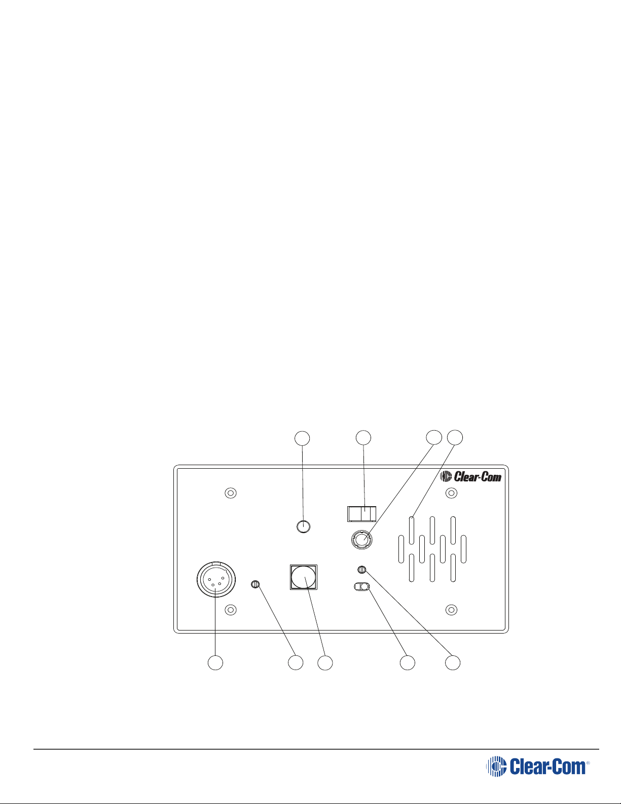
2.3.1 Front Panel
The controls, indicators, and connectors found on the KB-702 and KB-702GM/KB802GM-IM front panels are shown in the following figures and are described by the
following text. The numbers in the left column refer to the figures below
Page 10
Page 11

User Guide| KB-702/KB-702GM/KB-802-GM-IM
Speaker
Program Level
Off On
A
B
Channel Select
KB-702GM
Call
Talk
Sidetone
Headset
Panel Mic
VOX
Headset
Volume
Microphone
2-Channel
Speaker Station
6
7
3
4
9
2
8
1211
10
5
1
1. Talk Button and Indicator: The talk button activates the microphone feed to
the selected intercom channel. It has a dual action (momentary or latching)
depending upon how the button is pressed. If desired, the latching function can
be defeated using an internal option switch. The following describes the various
functions of this button.
l MOMENTARY: Press and hold the talk button while you are speaking. Release
it when you are finished. The button lights amber when the talk function is
active and blue when it is inactive.
l LATCHING: Press the button quickly to latch the talk function. Press the
l VOX INDICATION: On the KB-702GM/KB-802GM-IM, when the VOX feature is
button again to turn off the talk function.
enabled, the talk button illuminates amber to indicate an active talk, and the
VOX light illuminates amber to indicate that the panel microphone is in use.
This will automatically dip the speaker.
2. Call Button and Light: Pressing the call button will send a call signal on the
selected channel. All the call lights on that channel will then flash. Call signals
Page 11
Page 12

User Guide| KB-702/KB-702GM/KB-802-GM-IM
can also be sent while talking if required. The call button will light when pressed,
or whenever a call signal is present on the selected channel. An internal option
jumper can be set to allow the call button to light when a call signal is present
on either channel.
3. Tone Alert: An audible tone alert can be enabled to sound when a call signal is
received on the selected channel or either channel. This can be useful when the
operator’s attention has been drawn away from the KB-702 indicator panel. The
audible tone alert level can be adjusted or turned off by an internal control. The
tone alert will not sound if a call signal originates at the KB-702 station or if the
speaker on/off switch is turned off. The tone alert plays through both the
speaker and headset if the speaker on/off switch is turned on.
4. Volume Control: Turn this control to set the volume required on the speaker
or headset. This control does not affect the tone alert level or the program input
level.
5. Sidetone Control: Sidetone is the level of your own voice that you hear while
talking on the intercom. Setting a comfortable level of sidetone will ensure that
the intercom line sounds alive and also helps you modulate your voice relative
to other voices on the line.
Typically, different sidetone null settings are needed depending upon whether
you are using the speaker. Use one of the following procedures to correctly set
the sidetone level control.
Sidetone Adjustment Procedure for Headset:
a. Set the intercom level control to a comfortable level by having someone talk
to you from another station.
b. Press the talk button and speak into the microphone while turning the
sidetone null control slowly back and forth until you hear your voice at a
comfortable level in the headset.
Sidetone Adjustment Procedure for Gooseneck Mic (KB-702GM/KB802GM-IM only) or hand-held push-to-talk mic with the speaker
turned on:
Page 12
a. Set the VOX control fully counterclockwise to disable this feature.
b. Set the intercom level control to a comfortable level.
c. Press the talk button and speak into the microphone while turning the
sidetone null control slowly back and forth. There should be a point where
your voice (and any accompanying acoustic feedback) disappears. This is
the null point.
Page 13

User Guide| KB-702/KB-702GM/KB-802-GM-IM
d. Readjust the VOX control. (Refer to the VOX control paragraph in this
section.)
6. Program Level Control: Adjust the program level control to set the program
audio level heard in the headset or panel speaker.
Note: Do not force the trimpots past their stop points. This will damage
them.
7. Speaker On/Off Switch: The speaker on/off switch turns the front panel
speaker on or off. This switch also controls whether the tone alert is heard
through the speaker. The speaker volume will automatically dip whenever the
talk function is set, unless the VOX function is disabled.
8. Mic Select Switch (KB-702GM/KB-802GM-IM only): The mic select switch
selects whether the panel microphone or the headset microphone is active. If
the VOX feature is enabled, it is only operational when the panel microphone is
active.
9. Channel Switch: This switch selects whether the speaker station is active on
intercom channel A or channel B.
10. Headset Connector: The headset connector is located on the front panel. All
Clear-Com headsets are recommended for use with the KB-702. The Clear-Com
handheld push-to-talk microphone will also plug into the headset connector.
The following is a description of the characteristics of a suitable headset:
Mic Type --- Dynamic; see technical specifications for details
Headphone --- Dynamic; see technical specifications for details
The wiring of the headset is to be as follows:
Pin 1 --- Mic common
Pin 2 --- Mic hot
Pin 3 --- Headphone common
Pin 4 --- Headphone hot
The mic and headphone wiring in the headset cord must be individually shielded.
Do not connect pins #1 and #3 together. Headset extension cords or headset
“Y” cables are not recommended because they will increase crosstalk between
channels.
Page 13
11. Panel Mic Connector (KB-702GM/KB-802GM-IM only): Clear-Com
recommends the GM-9 and GM-18 plug-in panel microphones for use with the
KB-702GM/KB-802GM-IM. The GM-9 is 9 in. (23.04 cm) long and the GM-18 is 18
Page 14

User Guide| KB-702/KB-702GM/KB-802-GM-IM
in. (46.08 cm) long. Both are the electret type. The 1/4 in. (0.64 cm)phone jack
on the microphone mates with the panel mic receptacle on the front panel of the
KB-702GM/KB-802GM-IM.
To install a GM-9 or GM-18 microphone, use the following steps:
a. Remove the plastic plug from the jack, if present.
b. Check and unscrew the set screw in the mic mounting flange to make sure it
is clear of the threads in the bushing.
c. Screw the microphone into the bushing hand tight.
d. Turn the set screw on top of the mic mounting flange clockwise to lock the
microphone in place.
12. VOX Control (KB-702GM/KB-802GM-IM only): When the panel microphone
is selected on the KB-702GM/KB-802GM-IM, the VOX control should be adjusted
for proper operation. This control is located to the right of the panel mic
connector. Use a narrow flat blade screwdriver such as a greenie or tweaker for
this adjustment. When the adjustment is correctly set, the VOX light illuminates
amber when speaking into the panel microphone. Turning the control clockwise
makes the KB-702GM/KB-802GM-IM more sensitive to your voice. The VOX
feature can be disabled by turning the VOX control fully counterclockwise.
2.3.2 Internal Adjustments and Connections
The controls and connectors found inside the KB-702 are shown in the following
figure and described by the following text. The controls can be accessed without
completely removing the panel from its wall box or V-Box enclosure by removing
the top two screws and loosening the bottom two screws a few turns. Then lean the
panel out from the wall. The controls will then be accessible as shown in the lower
view of Figure 1-3. The numbers in the left column of the following descriptions refer
to Figure 1-3.
Page 14
Page 15

User Guide| KB-702/KB-702GM/KB-802-GM-IM
P1 Call
on Both
P1 Call on
Selected
P3 Must be
installed if
no option
P2 Must be
installed if
no option
1 2 3
15 16
17
1413
View from top
of KB-702
Front Panel
18
1. Call Alert Tone Level Control: This control adjusts the volume of the call
alert tone sound. This is normally adjusted when the system is set up and there
should be no need to adjust it in normal operation. This feature can be disabled
by turning the control fully counterclockwise.
2. Option Switches: Three option switches are provided. They should be
configured when the system is set up, but are not changed in normal operation.
Note the on position of each switch is toward the circuit board and the off
position is toward the front panel. The default position of the switches is in the
off position. The function of each switch is as follows:
a. SINGLE CHANNEL: In some installations, the KB-702 is intended to be used
only with one intercom channel. Setting the single channel switch to the on
position will connect the KB-702 to the one intercom channel regardless of
the position of the front panel channel selector. In two-channel installations,
this switch must be set to the off position.
b. LONG LINE: If a long cable run is unavoidable and approaches 700ft.
(213.5m) or more, set the long line option switch to the on position. The
ability to set a sidetone null depends upon properly setting this switch.
Page 15
c. LATCH DISABLE: Setting the latch disable switch to the on position will
disable the latching function of the talk button. In this mode, the talk button
must be continuously pressed while the operator is talking.
Page 16

User Guide| KB-702/KB-702GM/KB-802-GM-IM
One Channel
Cable Wiring:
KB-702 Intercom
Connector
XLR
Connector
Channel A
Pin 1
Pin 5
1
3
2
3. Call Signal Jumper: In some installations it is important to receive a call
signal from either channel, regardless of the setting of the channel selector. The
plug-on jumper P1 makes the call light respond to either (a) the selected
channel or to (b)either channel, depending upon its orientation. By default, the
jumper is set to the selected channel position. When the TW or 4-Wire Option
modules are installed, this jumper is not used. In TW operation, the call signal
always originates on channel A. In 4-Wire operation, the call signal is not used.
4. Intercom Line Connection: The KB-702 contains a 5-terminal plug-on
connector for intercom line connection. This connector is intended to be
unplugged from the circuit board when connecting the intercom line, and then
plugged back on when the wiring is completed. The connections for each pin are
visible on the circuit board when the connector is unplugged. The pinout of this
connector is as follows:
Pin 1 --- (NC)
Pin 2 --- Channel A Audio
Pin 3 --- Channel B Audio
Pin 4 --- Power
Pin 5 --- Ground (Shield)
Page 16
Page 17

User Guide| KB-702/KB-702GM/KB-802-GM-IM
Two Channel
Cable Wiring
KB-702 Intercom
Connector
XLR
Connectors
Channel A
Channel B
Pin 1
Pin 5
1
3
2
1
3
2
Program Input
Cable Wiring
KB-702 Program
Input Connector
XLR
Connector
Pin 1
1
3
2
Pin 3
5. Program Input: A 3-terminal plug-on connector provides the program input to
the station. Program is fed to the headset and speaker. The level to the speaker
or headset is controlled by the program level control. The program input accepts
a balanced or unbalanced line-level audio signal. If this input is connected to the
stage announce (SA) output of a main station it can be used as a paging input.
Since the level of this input is independently adjustable from the intercom audio
volume, it can be used to override the intercom audio.
Page 17
The pinout of the program input connector is as follows:
Pin 1 --- Ground (shield)
Pin 2 --- + Signal
Pin 3 --- - Signal
6. Option Board Jumpers:The three jumper plugs P1, P2, and P3 must be installed
when optional modules are not used. When the optional EB7-4W four-wire
module is used, both P1 and P3 must be removed. In the KB-702GM/KB-802GMIM, P2 is replaced by the VOX module. Save these jumper plugs for possible
future use after removing them. The KB-702 will not operate without
either these jumper plugs or the optional modules installed.
Page 18

3 Installation
1. Unpack the unit and inspect for any damage that may have occurred in
shipping.
2. Set the option switches to the default (up) position.
3. Connect the intercom lines. If only one intercom line is to be connected, turn
option switch #1 to the on or closed position.
4. Install the KB-702 into the four-gang outlet box or V-box. (For additional
information, refer to the Clear-Com System Installation Manual.)
5. Set listen levels and sidetones. (Refer to the listen level and sidetone setting
topics in the Operation chapter of this manual.)
6. The speaker station should now be operating properly.
7. Read the rest of this manual for further information.
User Guide| KB-702/KB-702GM/KB-802-GM-IM
Page 18
Page 19

User Guide| KB-702/KB-702GM/KB-802-GM-IM
EQ/
LIM
Headset
Mic
Ta lk
Sidetone
Null
Call
Light
Call
Intercom
Vol ume
Speaker
On/Off
TW Option
Channel
Switch
Ch. A
Speaker
Power
Ch. B
Call Send &
Receive
RMK
Microprocessor
Ta lk
Headset
Output
Balanced
Program
Input
Speaker
Dip
Program
Mute
Mic
Mute
Common
+30 VDC
Ground
Latch
Disable
Long Line
Program
Level
Call Alert
To ne Level
4-Wire
Input
4-Wire
Output
2-Wire / 4-Wire
Select
Rectifier
16 VAC
Power
Ch. B
Ch. B
Ch. A
Ch. A
4-Wire
Option
Single
Chan.
4 Maintenance
This chapter provides maintenance information including block diagrams and tips
for solving problems.
Caution:These servicing instructions are for use by qualified personnel
only. To reduce the risk of electrical shock, do not perform any servicing
other than that contained in the operating instructions unless you are
qualified to do so.
4.1 Block Diagram for the KB-702
4.2 Block Diagram for the KB-702GM/KB-802GM-IM
Page 19
Page 20

User Guide| KB-702/KB-702GM/KB-802-GM-IM
EQ/
LIM
Mic Select
Headset
Mic
Panel
Mic
Ta l k
Sidetone
Null
Call
Light
Call
Intercom
Vol ume
Red /
Green
Speaker
On/Off
TW Option
Channel
Switch
Ch. A
Speaker
Power
Ch. B
Call Send &
Receive
RMK
Microprocessor
Ta l k/
VOX
Headset
Output
Balanced
Program
Input
Speaker
Dip
Program
Mute
Mic Dip /
Mute
VOX
Common
+30 VDC
Ground
Latch
Disable
Long Line
Program
Level
Call Alert
To n e Level
4-Wire
Input
4-Wire
Output
2-Wire / 4-Wire
Select
Rectifier
16 VAC
Power
Ch. B
Ch. B
Ch. A
Ch. A
4-Wire
Option
Single
Chan.
Symptom Cause Solution
System does not
operate. Talk button
does not light.
No intercom connection to
the KB-702. If the EB7-4W
four-wire option module is
connected, the KB-702
may not be receiving AC
power.
Check connections and
cable.
The KB-702 has an internal
failure.
Unit requires servicing.
4.3 Troubleshooting
Page 20
Page 21

User Guide| KB-702/KB-702GM/KB-802-GM-IM
Symptom Cause Solution
Speaker does not
operate. Talk button
lights amber when
pressed.
Speaker switch turned off,
volume knob turned all the
way down, or channel
switch set to unused
channel.
Adjust controls
appropriately.
Speaker plug or wiring has
come loose.
Make sure speaker is
connected internally.
Plug P3 missing on circuit
board.
Plug P3 must be installed in
jack J3 if the EB-TW or EB74W options are not used.
Hum or buzz in system
Inductive pickup caused
by close proximity of this
speaker station or
connected stations to
power lines or
transformers.
Relocate the offending unit
or wiring. If the cable run is
exceptionally long, consider
adding and using the EB74W four-wire option
module. (Requires an
additional four-wire
interface at the opposite
end of the “long run.”)
System feedback
(Acoustical)
Intercom level control at
this station or another
station is set too high.
Adjust.
Sidetone null control at
this station or another
station is not adjusted
correctly.
Adjust. Refer to the chapter
“Operation.”
Channel not terminated.
Set the main station or
power supply termination
switch for that channel to
the on position.
Channel switch set to an
unconnected channel.
If only one intercom line is
connected, set option
switch #1 to the on or
closed position to link both
channel switch positions to
Page 21
Page 22

User Guide| KB-702/KB-702GM/KB-802-GM-IM
Symptom Cause Solution
the same intercom line.
A headset extension cord
was used.
Headset extension cords
are not recommended.
VOX problems (KB702GM/KB-802GM-IM
only)
Stays tripped (amber light
on). Sensitivity set too
high.
Turn VOX sensitivity control
in a counter-clockwise
direction.
Will not trip with voice.
Sensitivity set too low.
Turn VOX sensitivity control
in a clockwise direction.
Note: VOX is intended for
close-in operation.
Excessive crosstalk
High DC resistance has a
ground return.
Use heavier cable; add
additional conductor(s) to
ground return. If the cable
run is exceptionally long,
consider adding and using
the EB7-4W four-wire
option module.
Multi-channel cable pairs
are not individually
shielded.
Replace cable with
individually shielded pairs.
Headset cables are not
wired properly or shielded
properly.
Correct wiring. Use
headsets with properly
shielded wiring. Refer to the
chapter “Operation.”
Program signal sounds
distorted.
Program level control set
too high.
Turn the program level
control counter-clockwise.
Overload of program input
circuit.
Reduce the gain of the
program signal at the
source, such as an audio
mixer.
Call signal does not
function.
Excessive DC loading of
intercom line.
Remove any audio
transformers or other
equipment that may be
Page 22
Page 23

User Guide| KB-702/KB-702GM/KB-802-GM-IM
Symptom Cause Solution
connected across the
intercom line. If equipment
other than Clear-Com
intercom equipment must
be connected to the
intercom line, please
contact Clear-Com
application or service
personnel for information or
recommendations.
Far too many terminations
on the intercom line.
Check all main stations and
power supplies to make
sure each intercom channel
is terminated at only one
point.
Plug P1 missing on circuit
board.
Plug P1 must be installed in
jack J1 if the EB7-4W option
is not used.
Page 23
Page 24

User Guide| KB-702/KB-702GM/KB-802-GM-IM
5 Technical Specifications
5.1 KB-702/KB-702GM/KB-802GM-IM Two-Channel Speaker Stations
dBu is an absolute measurement. 0 dBu is referenced to 0.775 volts RMS
5.1.1 Panel Microphone Input (KB-702GM/KB-802GM-IM)
Input Type: Electret
Input Impedance: >=2KΩ
Mic Limiter Threshold: -2dBu ±3dB
Mic Limiter Range: >= 15dB
5.1.2 Headset Microphone Input
Input Type: Dynamic
Input Impedance: >= 1KΩ
Mic Limiter Threshold: -2dBu ± 3dB
Mic Limiter Range: >= 15dB
5.1.3 Program Line Input
Maximum Level before Clipping: >= 20dBu
Input Impedance: >= 5KΩ
5.1.4 Headset Output
Load Impedance: >= 8Ω
Output Impedance: <= 25Ω
Output Limiter Threshold: +5dBu ± 3dB
Maximum Output Level before Distortion: >= 17dBu
5.1.5 Speaker Output
Load Impedance: >= 4Ω
Max Output Level before 1% Distortion: 20dBu ± 2dBu
5.1.6 Party Line Output
Off Noise: < -74dBu
Page 24
Page 25

Output Impedance: >10KΩ
5.1.7 Party Line Input
Crosstalk: < -60dB
Max level before Clipping: >= 12dBu
Sidetone Null Capability (KB-702GM/KB-802GM-IM only):> 25dB
5.1.8 Frequency Response
Panel Mic - Party Line (KB-702GM/KB-802GM-IM only): 300 - 16KHz ± 3dB
Headset Mic - Party Line: 300 - 15KHz ± 3dB
Program Input - Headset Out: 200 - 18KHz ± 3dB
Program Input - Speaker Out: 200 - 18KHz ± 3dB
Party Line - Headset Out: 200 - 18KHz ± 3dB
Party Line - Speaker Out: 200 - 18KHz ± 3dB
User Guide| KB-702/KB-702GM/KB-802-GM-IM
5.1.9 Max Distortion
Panel Mic - Party Line (KB-702GM/KB-802GM-IM only):<= 0.5%
Headset Mic - Party Line: <= 0.5%
Program Input - Headset Out: <= 0.2%
Program Input - Speaker Out: <= 0.5%
Party Line - Headset Out: <= 0.2%
Party Line - Speaker Out: <= 0.5%
5.1.10 Noise
Panel Mic - Party Line (KB-702GM/KB-802GM-IM only):< -65dBu
Headset Mic - Party Line: < -70dBu
Program Input - Headset Out: < -60dBu
Program Input - Speaker Out: < -60dBu
Party Line - Headset Out: < -50dBu
Party Line - Speaker Out:< -50dBu
5.1.11 Max Gain
Panel Mic - Party Line (KB-702GM/KB-802GM-IM only):>= 37dB
Headset Mic - Party Line: 41dB ± 2dB
Program Input - Headset Out: >= 18dB
Page 25
Page 26

User Guide| KB-702/KB-702GM/KB-802-GM-IM
Program Input - Speaker Out:>= 24dB
Party Line - Headset Out: >= 34dB
Party Line - Speaker Out: >=40dB
5.1.12 Power
Input Voltage Range:20-30 VDC
Input Current (Idle):<= 90mA
Input Current (Max):<=110mA
5.1.13 Internal Adjustments and Connections
Intercom: Line:Five terminal connector
Program Input:Three terminal connector
Option Switches: Three DIP switches
Call Signal Jumper3:Three sets of options jumpers
Call Alert Tone Level Control:Level adjustment control
5.1.14 Front Panel Connectors
Panel Mic: (KB-702GM/KB-802GM-IM only):(1)1/4 in. (0.64 cm) panelmounting
jack
Headset: (1) XLR-4M
5.1.15 Front Panel Controls & Indicators (KB-702GM/KB-802GM-IM)
(1) Panel / headset mic switch
(1) Program monitor level control
(1) Sidetone null control
(1) Talk button
(1) Call button
(1) Speaker ON-OFF switch
(1) Channel select switch
(1) Speaker volume control
(1) VOX control
(1) VOX indicator
5.1.16 Front Panel Controls & Indicators (KB-702)
(1) Program monitor level control
Page 26
Page 27

User Guide| KB-702/KB-702GM/KB-802-GM-IM
(1) Sidetone null control
(1) Talk button
(1) Call button
(1) Speaker ON-OFF switch
(1) Channel select switch
(1) Speaker volume control
5.1.17 Environmental
32 - 122oF (0 - 50oC)
5.1.18 Dimensions (KB-702/KB-702GM/KB-802GM-IM)
8.25 in. W x 4.5 in. H x 1.75 in. D (210 mm x 114 mm x 44 mm)
5.1.19 Weight
KB-702 0.99 lbs. (0.45 Kg)
KB-702GM/KB-802GM-IM 1.1 lbs.(0.50 Kg)
5.1.20 Notice About Specifications
While Clear-Com makes every attempt to maintain the accuracy of the information
contained in its product manuals, that information is subject to change without
notice. Performance specifications included in this manual are design-center
specifications and are included for customer guidance and to facilitate system
installation. Actual operating performance may vary.
Page 27
Page 28

User Guide| KB-702/KB-702GM/KB-802-GM-IM
6 Technical Support and Repair Policy
To ensure that your experience with Clear-Com and our World Class products is as
beneficial, effective and efficient as possible, we would like to define the policies
and share some "best practices" that can accelerate any problem solving processes
which we may find necessary and to enhance your customer service experience.
Our Technical Support, Return Material Authorization, and Repair Policies are set
forth below. These Policies are subject to revision and constantly evolve in order to
address our Customers' and the Market's needs. Therefore, these are provided by
way of guidance and for information only and may be changed at any time with or
without Notice.
6.1 Technical Support Policy
a. Telephone, online, and e-mail technical support will be provided by the
Customer Service Center free of charge during the Warranty Period.
b. Technical support will be provided free of charge for all software products under
the following conditions:
i. The application, operating, and embedded software is installed on a product
covered by Clear-Com's Limited Warranty, and:
ii. The software is at the current release level; or,
iii. The software is one (1) version removed from current.
iv. Older versions of software will receive "best-effort" support, but will not be
updated to correct reported bugs or add requested functionality.
c. For Technical Support:
i. North and South America, (incl. Canada, Mexico, and the Caribbean) & US
Military:
Hours:0800 - 1700 Pacific Time
Days:Monday - Friday
Tel:+1 510 337 6600
Page 28
Email:Support@Clearcom.com
ii. Europe, the Middle East and Africa:
Hours:0800 - 2000 Central European Time
Days:Monday - Friday
Page 29

User Guide| KB-702/KB-702GM/KB-802-GM-IM
Tel:+49 40 853 999 700
Email:TechnicalSupportEMEA@clearcom.com
iii. Asia-Pacific:
Hours:0800 - 1700 Pacific Time
Days:Monday - Friday
Tel:+1 510 337 6600
Email:Support@Clearcom.com
d. Email Technical Support is available for all Clear-Com branded products free of
charge for the life of the product, or two years after a product has been
classified as obsolete, whichever comes first. To log or update a request, send
an email to: Support@Clearcom.com.
e. Support for Distributor and Dealer Sales
a. Distributors and Dealers may utilize the Customer Service Centers once a
system has been installed and commissioned. Clear-Com Systems and
Applications Engineers will provide support to the Distributor from the presales stage through to satisfactory installation for new system purchases.
Customers will be encouraged to contact their Dealer or Distributor with
their installation and technical support enquires rather than using the
Customer Service Centers directly.
f. Support for Direct Sales
i. Customers may utilize the Customer Service Centers once a system has
been installed and commissioned by Clear-Com Systems and Applications
Engineers, or in the case of project installations, once the Project Team has
completed the hand-over to the Support Centers.
6.2 Return Material Authorization Policy
a. Authorizations: All products returned to Clear-Com or a Clear-Com Authorized
Service Partner must be identified by a Return Material Authorization (RMA)
number.
Page 29
b. The Customer will be provided with an RMA number upon contacting Clear-Com
Sales Support as instructed below.
c. The RMA number must be obtained from Clear-Com via phone or email prior to
returning product to the Service Center. Product received by the Service Center
Page 30

User Guide| KB-702/KB-702GM/KB-802-GM-IM
without a proper RMA number is subject to return to the Customer at the
Customer's expense.
d. Damaged equipment will be repaired at the Customer's expense.
e. Returns are subject to a 15% restocking fee.
f. Advance Warranty Replacements (AWRs);
i. During the first 30 days of the Standard Warranty Period: Once the
equipment fault has been verified by Clear-Com or its authorized
representative, Clear-Com will ship a new replacement product. The
Customer will be provided with an RMA number and be required to return the
faulty equipment within 14 days of receipt of the replacement or will be
invoiced for the list price of a new product.
ii. During days 31-90 of the Standard Warranty Period: Once the equipment
fault has been verified by Clear-Com or its authorized representative, ClearCom will ship a like-new, fully refurbished replacement product. The
Customer will be provided with an RMA number and be required to return the
faulty equipment within 14 days of receipt of the replacement or will be
invoiced for the list price of a new product.
iii. To obtain an RMA number or request an AWR:
North and South America, Asia-Pacific, and US Military:
Hours:0800 - 1700 Pacific Time
Days:Monday - Friday
Tel:+1 510 337 6600
Email:SalesSupportUS@Clearcom.com
Europe, the Middle East and Africa:
Hours:0800 - 1700 GMT + 1
Days:Monday - Friday
Tel:+ 44 1223 815000
Email:SalesSupportEMEA@Clearcom.com
iv. Note: AWRs are not available for UHF WBS Analog wireless intercom
systems. UHF WBS Analog wireless intercom systems out-of-box failures
must be returned to Clear-Com for repair.
Page 30
Page 31

v. Note: Out-of-box failures returned after 90 days will be repaired and not
replaced unless approved by Clear-Com Management.
vi. Note: AWRs are not available after 90 days of receipt of product unless an
AWR Warranty Extension is purchased at the time of product purchase.
vii. Note: Shipping charges, including duties, taxes, and insurance (optional), to
Clear-Com's factory are the responsibility of the Customer.
viii. Note: Shipping AWRs from Clear-Com is at Clear-Com's expense (normal
ground or international economy delivery). Requests for expedited shipping
(E.g. "Next-Day Air"), customs duties, and insurance are the responsibility
of the Customer.
6.3 Repair Policy
a. Repair Authorizations: All products sent to Clear-Com or a Clear-Com
Authorized Service Partner for repair must be identified by a Repair
Authorization (RA) number.
User Guide| KB-702/KB-702GM/KB-802-GM-IM
b. The Customer will be provided with an RA number upon contacting Clear-Com
Customer Services as instructed below.
c. The RA number must be obtained from Clear-Com via phone or email prior to
returning product to the Service Center. Product received by the Service Center
without a proper RA number is subject to return to the Customer at the
Customer's expense.
d. Return for Repair
i. Customers are required to ship equipment at their own cost (including
transportation, packing, transit, insurance, taxes and duties) to Clear-Com's
designated location for repair.
Clear-Com will pay for the equipment to be returned to the Customer when it
is repaired under warranty
Shipping from Clear-Com is normal ground delivery or international
economy.
Requests for expedited shipping (E.g. "Next-Day Air"), customs duties, and
insurance are the responsibility of the Customer.
Page 31
ii. Clear-Com does not provide temporary replacement equipment ("loaner")
during the period the product is at the factory for repair. Customers should
consider a potential prolonged outage during the repair cycle, and if required
Page 32

User Guide| KB-702/KB-702GM/KB-802-GM-IM
for continuous operations purchase minimum spare equipment required or
purchase an AWR Warranty Extension.
iii. No individual parts or subassemblies will be provided under warranty, and
warranty repairs will be completed only by Clear-Com or its Authorized
Service Partner
Page 32
 Loading...