

Page 1
KB-112
Speaker
Station
INSTRUCTION
and
SERVICE
MANUAL
I
i
~jliClear-Com
IF
Iintercom
Systems
945
Camelia
St.
Berkeley,
California
94710
510-527-6666
Clear-Com
810027
8/15/88
REV.
C
Page 2
KB-112
RENOTE
STATION
OPERATION
&
SERVICE
MANUAL
Table
of
Contents
Section
Page
I
Introduction
to
the
KB-112
................
1
II
Installation
..............................
3
III
Operation
.................................
4
IV
Parts
Listing
.............................
7
V
Technical
Theory
of
Operation
.............
7
VI
Specifications
............................
9
Illustrations
Figure
1:
KB-112
Mounting
Dimensions
.........
2
Figure
2:
Portable
Unit
Connection
...........
2
Figure
3:
PC
Board
Lay-Out
...................
5
Figure
4:
Typical
Program
Feed
...............
6
Figure
5:
Block
Diagram
......................
8
Figure
6:
KB-112
Schematic
...................
9
Page 3
I.
INTRODUCTION
TO
THE
1B-112
REMOTE
SPEAKER
STATION
The
KB-112
is
a
versatile,
single-
112's
operator.
channel
Remote
Station
that
pro-
vides
two-way
(talk/listen)
com-
municating
ability.
Compatible
The
KB-112
front
panel
contains
a
with
all
Clear-Com
intercoms,
the
red
LED
that
lights
whenever
the
KB-112
is
ideal
in
places
where
mic
is
active.
This
is
especially
wearing
a
headset
is
not
feasible:
helpful
when
your
KB-112
is
remote-
dressing
rooms,
security
entrances,
ly
controlled;
the
LED
shows
that
etc.
The
KB-112
has
a
push-to-talk
another
station
operator
has
turned
electret
mic
and
a
built-in
speaker
on
your
mic.
with
a
wide
frequency
response.
Other
KB-112
features
are
intercom
OPERATING
MODES
volume
control,
Visual
Call
Signal
The
KB-112
features
"control
logic"
button,
and
amber
Call
lamp.
CMOS
circuitry
for
programming
the
operation
of
the
station.
This
allows
remote
or
local
control
(or
PROGRAM
INPUT
both)
of
the
speaker
and
the
mic.
If
desired,
you
can
monitor
exter-
The
station
operator
pre-sets
a
nal
program
via
the
KB-112;
its
bank
of
dip
switches
that
are
lo-
wiring
terminal
strip
includes
an
cated
on
the
electronics
module.
access
point
for
input
from
the
If
pre-set
for
remote
control,
the
auxiliary
audio
source.
The
station
KB-112
speaker
and/or
mic
can
be
accepts
an
unbalanced,
line-level
activated
by
all
other
Clear-Com
singal
from
audio
gear
such
as
mic
stations
(on
the
same
channel,
mixers
or
portable
amps,
and
mixes
using
the
visual
signal
circuitry).
it
with
the
intercom
output
from
the
speaker.
The
KB-112's
operating
modes
are:
NORMAL:
Speaker
is
on.
Mic
is
locally
activated
by
pushbutton
on
INSTALLATION
front
panel.
The
KB-112
is
a
custom-mounting
station;
its
non-glare,
charcoal-
REHOTE
PACE:
Speaker
is
off
except
brown,
aluminum
front
panel
in-
when
turned
on
by
remote
control,
stalls
in
a
cut-out
in
the
wall
or
used
to
page
anyone
at
that
KB-
a
console,
or
inside
a
standard
6"
112's
location.
Mic
is
activated
x
8"
Nema
Type
1
box.
locally.
For
portable
use,
you
can
install
REMOTE
LISTEN:
Speaker
is
on.
Mic
the
KB-112
in
Clear-Com's
"P-Box,"
is
turned
on
locally
OR
by
remote
a
rugged,
lightweight
aluminum
en-
control,
which
allows
that
KB-112
closure
with
a
sloped
front,
walnut
operator
to
talk
"hands-free."
side
panels,
and
a
carrying
strap.
It
provides
3-pin
XLR
connectors
REMOTE
LISTEN-PAGE:
Speaker
is
nor-
for
input
and
extension.
mally
off.
Mic
remains
on
for
hands-free
talking.
Another
sta-
The
KB-112
connects
to
the
intercom
tion
can
turn
off
the
mic
and
turn
system
with
standard,
two-conductor
on
the
speaker
for
paging
that
KB-
(individually-shielded)
mic
cable.
Page 4
KB-112
MOUNTS
IN
*
86.
>1
A
.
P
e
RACK
EOX
0
5.4'
6.5'
KB-
-
12
-
qoup
MOUNVT/PIG
DIMENSIONVS
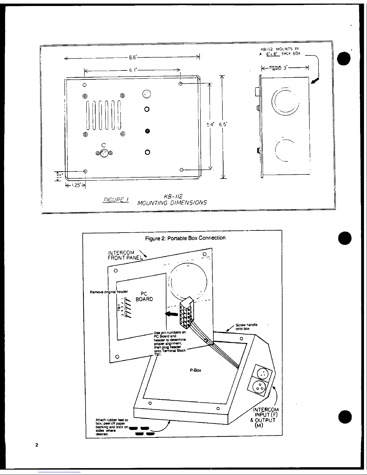
Figure
2:
Portable
Box
Connection
I
11
(~~Rm
ov
ohire
heade
PC
.
0~~~~
i
IG'
P'
PC
[l~~~~~~~~~~~~~~~w
M
CNIG DIMNSI
BOck
Fin
re
2
PnrableBox
nne
tn
INTERCOM
\
~~~~~~~~~~~~~I
1
°."
p"ofpp
backing~~~~~~~r
and
umr
on
(M)
--
sl
>
dnoa
O
/
2~~~i
rs
K
Page 5

.1.
INSTALLATION
OF
THE
KB-112
The
KB-112
can
be
mounted
in
a
cut-
To
install
the
KB-112
in
the
P
Box:
out
in
any
surface,
or
it
can
mount
inside
a
6"
by
8"
Bl
ack
1)
Remove
the
plastic
header
from
(electrical)
Box
(minimum
depth,
the
terminal
block
(TBI)
on
the
3").
See
figure
1
for
dimensions.
KB-112
PC
Board;
pull
straight
up
to
lift
header
off.
The
KB-112
connects
to
the
intercom
system
through
its
five-screw
ter-
2)
A
similar
header
is
wired
to
the
minal
strip
(designated
as
"TB-i"
P-Box's
3-pin
connectors;
plug
on
the
PC
Board
Lay-Out;
see
Figure
that
header
onto
terminal
block
3).
Route
two-conductor,
shielded
TB-1.
The
header,
terminal
block
cable
(i.e.
Belden
8762)
from
the
and
PC
Board
are
clearly
la-
Main
Station
or
Power
Supply
output
belled
with
the
pin
numbers
to
connector
to
the
KB-112's
location.
ensure
proper
connections.
See
Unshielded
cable
may
be
used
where
Figure
2,
Portable
Unit
Connec-
AC
interference
is
not
a
problem.
tion.
After
preparing
a
surface
for
in-
3)
Attach
the
KB-112
to
the
enclo-
stallation
(refer
to
Fig.
1),
bring
sure
using
the
supplied
screws.
wiring
into
the
header
on
TBI
(the
If
desired,
attach
the
handle
terminal
block),
and
connect
leads
and
the
protective
rubber
feet
according
to
the
following
TB-i
pin
on
the
suitable
sides.
The
assignments:
enclosure
also
has
cut-outs
on
each
side
for
hanging
it,
in
any
Pin
1--Chassis
Ground
position,
from
the
wall,
a
con-
Pin
2--Program
Input
sole,
or
where
desired.
(or
no
connection)
Pin
3--Intercom
Audio
Use
standard
two-conductor
mic
ca-
Pin
4--+30
volts
DC
ble
to
interconnect
the
portable
Pin
5--Common
station
within
the
intercom
system.
The
pin-out
assignment
for
each
XLR
The
KB-112
may
be
mounted
inside
connector
is:
the
Clear-Com
Model
"P"
Box,
there-
by
becoming
a
portable
Remote
Sta-
Pin
1--
common
tion.
The
"P"
Box
is
a
sloped-
Pin
2--
+30
volts
DC
front,
sturdy
steel
enclosure
sup-
Pin
3--
intercom
audio
plied
with
a
handle,
rubber
feet,
and
screws
for
attaching
the
handle
Route
cable
from
the
Main
Station/
and
the
intercom
to
the
chassis.
Power
Supply
(or
other
Remote
Sta-
tion)
to
the
portable
KB-112
and
When
the
KB-112
is
mounted
in
the
input
to
the
female
connector.
Use
portable
enclosure,
it
connects
to
the
male
output
connector
to
the
intercom
system
with
the
3-pin,
"daisy-chain"
the
intercom
line
XLR-type
connectors
located
on
the
between
the
KB-112
and
another
side
of
the
chassis.
There
is
one
portable
Remote
Station.
female
connector
for
the
input
and
one
male
connector
for
extending
the
intercom
line
to
other
sta-
Before
operating
either
the
KB-112
tions.
Inside
the
box,
the
connec-
or
installing
it
in
the
portable
tors
are
wired
to
a
5-pin
header,
enclosure,
be
sure
that
the
unit's
which
you
plug
onto
the
terminal
dip
switches
are
set
to
the
desired
block
on
the
KB-112
PC
Board.
positions.
3
Page 6

111.
OPERATING
CONTROLS
The
KB-112
controls
are
straight-forward
and
simple
to
use.
The
Voluse
control
adjusts
the
your
channel.
listen-level
of
the
speaker.
The
other
important
feature
of
the
The
red
Call
push-button
activates
Call
button
is
its
ability
to
acti-
the
intercom
system's
Visual
Sig-
vate
the
mic
and/or
speaker
of
any
nalling
circuit.
The
signal
re-
KB-112
(on
the
same
channel)
that
mains
active
as
long
as
you
press
is
pre-set
for
remote
control.
the
Call
button.
It
allows
you
to
attract
the
attention
of
operators
The
Call
Light
on
the
KB-112
lights
who
have
removed
their
headsets,
by
up
when
another
station's
operator
illuminating
the
Call
lights
at
all
(on
the
same
channel)
presses
the
stations
that
are
communicating
on
Call
button.
ALTERNATE
OPERATING
MODES
At
the
factory,
Clear-Com
sets
the
KB-112
for
the
NORMAL
operating
mode.
To
pre-set
the
KB-112
for
Remote
Page,
Remote
Listen,
or
Remote
Listen-Page,
change
the
position
of
one
or
more
dip
switches
(designated
as
53-1,
S3-2,
S3-3,
and
53-4).
See
Figure
3,
PC
Board
Lay-Out,
for
the
location
of
these
switches.
The
chart
below
describes
the
functions
that
occur
during
each
set-up,
and
which
switch
positions
enable
these
functions.
Switch
Setting
OPERATING
MODE
S3-2
S3-3
S3-4
"Normal"
-speaker
is
on
-mic
activated
by
front
panel
push-button
ON
OFF
ON
"Remote
Page"
-speaker
turns
on
by
remote
control
-mic
activated
by
front
panel
push-button
ON
ON
ON
"Remote
Listen"
-speaker
is
on
-mic
activated
by
remote
control
ON
OFF
OFF
"Remote
Listen-Page"
-speaker
turns
on
by
remote
control
OR
by
front
panel
push
button
-mic
is
normally
on
OFF
OFF
OFF
4
Page 7

Figure3
KB-
12
PC
BOARD
LAY-OUT
SWITCHING
0
a
.
*,TI
kO
CONTROL
"C
Qa
~
~
~
~~~~~~~S-2'EVRELOGIC'
~https://manualmachine.com/.
.
R
E~
~f
J
SWITCHES
(
2
_
-53-2
534/
l
--
1
-49002$O
3-1
"MICUS
5
3-4
-
o,
S~~~~~~~t
Sets
micgain
for
distant
orcIoseuse
,,
s
2
<
~~~~~~~~~~~~~~~ON:
Distant
(high
sensitivity)
OFF:
Close
(lovwsensitivity)
ON:
Normal
Logic
OFF:
Reverse
Logic
53-3
'LISTEN
LOGIC"
ON:
Speaker
Control
Remote
Remote
Control
of
Mic
OFFt
Speaker
Control
Local
Connect
the
points
of
aremote
Push-to-Talk
button
('
...
entary-
O34
STALKeLOGICo
on'
type)
to
the
top
(Comcon)
and
middle
(N.0.)
terminals
of
OL
LIC"
OFF:
Mic
Control
Remote
switch
S-I
(next
to
C-20)
on
the
PC
Board.
OFMcoto~m
USING
THE
MIC
When
set
up
for
the
Normal,
Remote
nel)
wants
to
page
the
KB-112
ope-
Page,
or
the
Remote
Listen
mode
of
rator.
The
remote
operator
then
operation,
the
black
push-button
on
presses
his
Call
button,
which
the
KB-112
front
panel
determines
turns
off
the
KB-112
mic
and
LED
the
mic's
activity.
To
talk
on
the
and
turns
on
the
KB-112
Call
Light
intercom
channel,
press
this
and
speaker.
button.
As
long
as
you
press
it,
the
mic
is
"on"
and
the
red
LED
above
it
lights
up,
indicating
that
Distance
from
Mouth
to
Mic:
other
operators
can
hear
you.
A
fourth
internal
dip
switch
(des-
When
set
up
for
Remote
Listen,
the
ignated
as
"53-1")
determines
how
mic
will
also
turn
on
when
another
close
you
should
be
to
the
mic
when
Station
(which
must
be
on
the
same
talking.
This
switch
is
normally
channel)
activates
the
Call
cir-
set
to
"off,"
which
means
you
cuit.
This
allows
the
KB-112
opera-
should
be
within
two
feet
of
the
tor
to
talk
"hands-free."
The
mic-
front
panel
when
talking
into
the
on
LED
and
the
Call
Light
both
mic
(i.e.,
during
the
Normal
and
illuminate
when
a
remote
operator
Remote
Page
modes).
turns
on
the
mic.
However,
you
should
change
the
dip
When
set
up
for
Remote
Listen-Page
switch
to
"on"
when
talking
into
the
mic
remains
on,
so
the
1B-112
the
mic
will
occur
from
a
greater
operator
can
talk
"hands-free."
The
distance,
i.e.
during
Remote
Listen
mic
and
the
mic-on
LED
are
on
until
or
Remote
Listen-Page
(when
the
another
Station
(on
the
same
chan-
operator
can
talk
hands-free).
Page 8

USING
THE
SPEAKER
When
the
KB-112
is
set
up
for the
activates
the
Call
circuit.
That
Normal
mode
or
the
Remote
Listen
Station
must
be
connected
to
the
mode,
its
speaker
stays
"on"
so
the
same
channel used
by
the
KB-112.
operator
can
monitor
activity
on
the
intercom
channel.
When
the
When
the
KB-112
is
set
up
for
the
operator
turns
on
the
mic
(or
if
Remote.Listen-Page
mode,
the
spea
the
mic
is
turned
on
from a remote
ker
stays
off
EXCEPT
when
another
location),
the
speaker
automatical-
Station
activates
the
"Call"
cir-
ly
shuts
off.
cuil:.
Due
to
the
nature
of
the
reverse
logic,
when
in
this
mode
When
the
KB-112
is
set
up
for
the
the
KB-112
operator
can
also
turn
Remote
Page
mode,
the
speaker
can
on
the
speaker
by
pressing
the
turn
on
only
when
another
Station
black
"push-to-talk"
button.
USING
THE
EXRNAL
PROGRAM
INPUT
mixing
console,
the
output
of
a
If
your
intercom
is
used
in
thea-
mini
mic-mixer,
the
pre-amp
output
trical
or
musical
production,
the
of
an
amp,
etc.
KB-112's "Program
Input"
might
be
useful.
It
enables
you
to
listen
to
Use
single-conductor,
shielded
ca-
an
external
audio source
in
addi-
ble
to
input
"program"
to
the
KB-
tion
to
the
intercom
audio.
Simply
112.
Connect
the
hot lead
from
feed
an
unbalanced,
line-level
sig-
your
source
to
terminal
2
on
the
nal
to
the
KB-112
terminal
strip. KB-112
terminal
strip,
and
connect
the
ground
lead
from
your
source
to
This
application
works
when
the
KB-
terminal
5.
112
is
set
up
for
"Normal,"
"Remote
Page,"
or
"Remote
Listen"
mode
of
If
a
balanced
input
is
desired,
operation.
The
program
audio
is
insert
a
balancing
transformer
completely
isolated
from
the
inter-
between
the
KB-112's access point
com
audio,
and
is
cut
off
when
the
and
the
program
source.
KB-112's
mic
is
activated.
The
program
volume
is
adjustable
Connecting
The
Input
from
the
source
end;
use
the
audio
The
program
access
point
is
high-
source's
VU
meter
reading
as
a
impedance,
about
500k
ohms.
There-
volume control
reference.
Or
for
fore
it
can
be
driven
by
an
audio
local
control
of
the
program
vol-
device
of
virtually
any
impedance;
ume,
refer
to
the
set-up
shown
in
it
could
be
the
monitor
buss off
a
Figure
4,
Typical
Program
Feed.
Figure
4:
TYPICAL
PROGRAM
FEED
OdB
3
Line-Level
Output
_
;L4
>
~~~~~GND.
5
PRO
GRAM
VOLUME
CrONTROL'
10Dk
OHMAUDIOTAPER
'Volume
Control
is
optional.
If
desired,
it
6
ma
beinlstalledateithertheKB-112end
or
the progra
source
end.
Page 9

e|
IV.
PARTS
LISTING
Part
#
Description
Qty.
Schematic
Reference
Desig.
710133
KB-112
PC
Module
Assembly
I
250156
Front
Panel
I
500089
Speaker,
3"
round,
16
ohm
I
SPi
250054
Speaker
screen,
3"
470037
Trimpot
(volume)
1
P1
500056
Mic,
electret
1
Ml
640005
Mic
bushing
640027
Rubber
mount
for
mic
390000
Lamp,
amber
1
11
390007
Red
LED
1
12
510028
Switch,
momentary
push
2
S1,
S2
240020
Switch
cover,
red
(1)
240021
Switch
cover,
black
(1)
280067
Dress
cone
nut
(2)
210085
Terminal
Strip,
5-screw
I
TBI
210086
Header
(5)
250178
Terminal
Strip
label
1
250193
Dip
Switch
label
1
210002
Intercom
Input,
D3M
1
31
(P
Box)
210003
Intercom
Output,
D3F
1
J2
(P
Box)
240003
Handle
I
P
Box
240010
Rubber
foot,
1/2"
square
8
P
Box
810027
Instruction
Manual
1
V.
THEORY
OF
REMOTE
STATION
OPERATION
Refer
to
the
KB-112
Schematic
(last
dB
loss
in
audio
level.
page)
when
reading
this
section
for
a
clearer
understanding
of
what
The
KB-112
is
a
"half-duplex"
de-
occurs
during
KB-112
operation.
vice,
which
means
that
its
operator
cannot
simultaneously
talk
and
lis-
The
KB-112
incorporates
Clear-Com's
ten;
only
one
action
may
occur
at
a
high-impedance
bridging
method,
so
time.
it
connects
to
the
intercom
line
without
taking
appreciable
power
During
"normal"
operation,
the
from
the
line.
This
enables
up
to
speaker
remains
on
and
the
mic
off.
20
Stations
to
be
connected
on
one
The
Push-To-Talk
button
(Sl
in
the
line
extending
from
the
Main
Sta-
Schematic)
shuts
off
the
speaker
tion
or
Power
Supply,
with
only
a
6
and
turns
on
the
mic;
this
button
7
Page 10

works
with
the
Control
Logic
cir-
17
diB)
and
to
the
line
buffer
amp
cuitry
in
order
to
operate
the
(IC1-2).
The
line
buffer
feeds
analog
switches.
For
this
to
hap-
part
of
the
signal
back
to
the
pen,
the
dip
switches
S3-2
and
53-4
bridging
circuit,
raising
the
line
should
be
closed.
This
means
the
impedance
to
l5k
ohms.
When
the
output
of
IC3-2
is
low.
mic
is
off,
the
mic
preamp
gain
is
reduced
to
unity,
reducing
any
When
the
P-T-T
switch
is
activated,
noise
in
the
input
circuitry
by
30
the
output
of
IC3-2
goes
high.
dB.
When
dip
switch
S3-1
goes
from
This
causes
the
output
of
IC3-3
to
open.
to
closed,
the
gain
adjustment
go
high,
turning
on
the
"mis-on"
of
the
mic
input
is
increased
by
7
LED.
The
high
voltage
goes
to
the
dB.
input
of
R8,
which
turns
on
FET
Q2,
shutting
off
amplifier
IC2.
The
The
VISUAL
CALL
SIGNAL
is
accom-
same
high
level
also
turns
on
YET
plished
by
impressing
DC
voltage
on
Q3
and
supplies
power
to
the
elec-
the
audio
line.
Pressing
the
Call
tret
miC,
completing
the
feedback
button
(S2)
turns
on
transistor
Q6,
loop
of
IC1-1,
thus
turning
on
the
applying
about
11
volts
to
the
mic
pre-amp.
intercom
line.
A
receive-call
sig-
nal
entering
a
KB-112
is
detected
By
changing
the
settings
of
the
by
transistor
Q5,
which
in
turn
is
Control
Logic
dip
switches
(S3-2
to
detected
by
a
darlington
amp
which
S3-4),
we
change
the
control
vol-
turns
on
the
Call
light
(11;
during
tages
going
to
the
digital
ampli-
alternate
operating
modes
when
dip
fiers,
making
different
operating
switch
S3-3
is
closed,
the
same
modes
possible.
control
voltage
is
also
used
to
activate
the
mic
and
speaker
amp
on/off
functions).
The
call-receive
Communication
Circuitry
circuit
requires
only
4
volts
(at
In
the
"Talk"
circuit,
signals
from
100
ma)
to
turn
on
the
light.
The
the
mic
are
amplified
44
dB
by
a
7-volt
difference
between
the
send
low-level
preamp
(ICl-1).
Preampli-
and
receive
voltages
assures
posi-
fied
signals
are
sent
to
the
audio
tive
signalling,
even
on
very
long
line
(where
they
are
attenuated
by
lines.
KB-112
BLOCK
DIAGRAM
REFVE
qSE
11CCPiART
v~~~~R
CTCC
To
cwl7
CALL"
LICHT
CALL
INTERC
tOM
V.
~~~~~AUDIO
-
LED
E~~RT x.
PROOC.
rIC
ON
R
vE
UO
TERMINAL
EL
,CV
CURRENT
vONTRL
GROuND
AICR~~~~~~~~~~PH5NE~~~~~~EMT
Page 11

VI.
1K-112
SPECIFICATIONS
AMPLIFIER
DESIGN
Solid-state,
integrated
circuit
amps
including
a
mic
preamp,
speaker
power
amp,
signalling
circuit,
logic
control
circuit.
Current-limited
with
short-circuit
and
reverse
polarity
protection.
MIC
PREAMPLIFIER
GENERAL
SPECS
Freq.
Response:
200-12k
Hz,
con-
Station
Bridging
toured
to
enhance
intelligibility
Impedance:
18k
ohms
(200-10k
Hz)
Mic
Preamp
Gain:
Power
Requirements:
25
dB,
low
sensitivity
17
ma
quiescent,
60
ma
average
talk
31.5
dB,
high
sensitivity
60
ma
signalling,
60
ma
remote
con-
Mic
Type:
electret
trol,
200
ma
short
circuit
Voltage
Range:
12-32v,
28v
nominal
SPEAKER
AMPLIFIEU
Line
Level:
I
dB
max
Speaker
Type:
3"
round,
16
ohm
Signal
Voltage:
11VDC
on
audio
line
Power
Output:
2
watts
into
16
ohms
Call
Light
Sensitivity:
4
volts
Freq.
Response:
100-15k
Hz,
±
3
dB
Aux.
Input
Impedance:
500k
ohms
Signal-to-Noise:
75
dB
Aux.
input
Level:
.7v
for
max
ouput
Equivalent
Input
Noise:
121
dB
Line-to-Speaker
Gain:
30.5
dB
Distortion:
0.5%
THD
at
Ik
Hz
DIMENSIONS
(front
panel):
Speaker
Level:
98
dB
@
3
feet
8.6"
wide
x
6.5"
high
x
1.4"
deep
NOTE:
"WHILE
CLEAR-COM
MAKES
EVERY
ATTEMPT
TO
MAINTAIN
THE
ACCURACY
OF
THE
INFORMATION
CONTAINED
IN
ITS
PRODUCT
MANUALS.
THE
INFORMATION
IS
SUBJECT
TO
CHANGE
WITHOUT
NOTICES
9
Page 12

0
_
,J__I
|
,
>
7
4
_
s
0
0
t,>,
-XJ7G~~~~~i
l
=,
t
,
ti0~~~~~
X
C
4
1
11&~~~~~~~~~~~~~~~~elL
\
X
ri
t2
@U~~~~~~~~~~~~~~~~~~>>
t,
,<
:
Hl
,
,,z
J
rt
a
9='
e
r
r
_
_
~
-
=
J
'.1'<~~~~~~~~~~~~~~~~~~~~~~~~~~~~C
Nf,
L_
-
-
-
-
-E~~C3-
2 C-o>
¢
Fl>°sll}
M'
"WSWE
 Loading...