

Page 1
I-Series Panels
User Guide
PN: 399G056 Rev: A 08/22/13
Page 2

Document Reference
I-Series Panels User Guide
Part Number: 399G056 Revision: A
Legal Disclaimers
Copyright © 2013 HME Clear-Com Ltd.
All rights reserved.
Clear-Com, the Clear-Com logo, and Clear-Com Concert are trademarks or registered
trademarks of HM Electronics, Inc.
The software described in this document is furnished under a license agreement and may
be used only in accordance with the terms of the agreement.
The product described in this document is distributed under licenses restricting its use,
copying, distribution, and decompilation/reverse engineering. No part of this document
may be reproduced in any form by any means without prior written authorization of ClearCom, an HME Company.
Clear-Com Offices are located in California, USA; Cambridge, UK; Montreal, Canada; and
Beijing, China. Specific addresses and contact information can be found on Clear-Com’s
corporate website:
www.clearcom.com
Clear-Com Contacts
Americas and Asia-Pacific Headquarters
California, United States
Tel: +1.510.337.6600
Email: CustomerServicesUS@clearcom.com
Europe, Middle East, and Africa Headquarters
Cambridge, United Kingdom
Tel: +44 1223 815000
Email:
Canada Office
Quebec, Canada
Tel: +1 (450) 653-9669
China Office
Beijing Representative Office
Beijing, P.R.China
Tel: +8610 65811360/65815577
SalesSupportEMEA@clearcom.com
2
I-Series Panels User Guide
Page 3

Contents
1 Important Safety Instructions ....................................................................... 7
Safety symbols .................................................................................................................. 8
Mains power cord .............................................................................................................. 8
2 Introduction ................................................................................................... 9
2.1 I-Series user panels covered by this guide ...................................................... 9
2.2 Terminology .................................................................................................... 9
2.2.1 Labels ................................................................................................................... 10
2.3 Further information ........................................................................................ 10
3 Overview ...................................................................................................... 11
3.1 Features ........................................................................................................ 11
3.2 Chassis assembly ......................................................................................... 12
3.3 Modules ........................................................................................................ 12
3.3.1 Key module ........................................................................................................... 12
3.3.2 Function Key module ............................................................................................ 13
3.3.3 Mic-headset module ............................................................................................. 14
3.3.4 Level control module ............................................................................................ 14
3.3.5 AUX-101 auxiliary options module ....................................................................... 15
3.4 Standard I-Series user panel configurations .................................................. 15
4 Using I-Series panels .................................................................................. 17
4.1 Powering up I-Series panels .......................................................................... 17
4.1.1 Powering up panels with non-display key modules .............................................. 17
4.1.2 Powering up panels with display key modules ..................................................... 17
4.1.3 Powering up panels with a function key module .................................................. 18
4.2 Front panel controls and lights ...................................................................... 18
4.2.1 Non-latching keys ................................................................................................. 18
4.2.2 Latching keys ........................................................................................................ 18
4.2.3 Active and Non-Ac ti ve Keys ................................................................................. 18
4.2.4 Alternative text key ............................................................................................... 19
4.3 Using keys to indicate status ......................................................................... 19
4.3.1 Call waiting light (ANSWR key) ............................................................................ 19
4.3.2 In use light ............................................................................................................ 20
4.3.3 Telephone off-hook light ....................................................................................... 20
4.3.4 Radio-receiver active light .................................................................................... 21
4.3.5 Panel connected light ........................................................................................... 21
3
I-Series Panels User Guide
Page 4

4.3.6 Audio-presence light ............................................................................................. 21
4.3.7 Incompatible firmware light ................................................................................... 22
4.4 Key module lights (summary) ........................................................................ 22
4.5 Answer-back (ANSWR) ................................................................................. 22
4.5.1 Using the Answer-back (ANSWR) and Clear (CLEAR) keys ............................... 23
4.5.2 Answer-back (ANSWR) and Clear (CLEAR) key lights (summary) ..................... 25
4.6 Speaker and headset volume controls .......................................................... 25
4.6.1 Adjusting the main volume ................................................................................... 25
4.6.2 Adjusting the program input volume ..................................................................... 26
4.6.3 Adjusting listen levels ........................................................................................... 26
4.6.4 Resetting listen levels to the default level ............................................................ 28
4.7 Upgrading the I-Series panel firmware .......................................................... 28
5 Using the basic function keys .................................................................... 30
5.1 The four basic function keys .......................................................................... 30
5.2 Turning the gooseneck microphone on and off .............................................. 31
5.2.1 Switching from the gooseneck microphone to the headset .................................. 31
5.3 Turning the headset microphone on and off .................................................. 31
5.3.1 Switching from the headset to the gooseneck microphone .................................. 31
5.4 Turning the speaker on and off ...................................................................... 32
5.5 Using the Listen (LISTEN) key ...................................................................... 32
5.5.1 Placing a talk-with-listen key in monitor mode ..................................................... 33
5.5.2 Sending call signals .............................................................................................. 33
5.5.3 Releasing remote telephone lines ........................................................................ 34
5.6 Function key module lights (summary) .......................................................... 35
6 Using the advanced features ...................................................................... 36
6.1 Accessing advanced features ........................................................................ 36
6.1.1 Advance features accessed by the numeric keypad (summary) .......................... 37
6.2 Telephone dialing from the keypad (#1 key) .................................................. 37
6.3 Accessing Local Exclusive (#2 key) ............................................................... 38
6.4 Local Page Override (#3 key) ........................................................................ 38
6.5 IFB, partyline and Fixed Group assignments (#4 key) ................................... 39
6.5.1 Setting up IFB sources and destinations .............................................................. 39
6.5.2 Setting up partyline members ............................................................................... 40
6.5.3 Setting up Fixed Group members ........................................................................ 40
6.6 Local Key Assignment (#5 Key) .................................................................... 41
6.6.1 Assigning a remote destination to a talk or talk-with-listen key ............................ 41
6.6.2 Clearing a talk assignment ................................................................................... 42
6.6.3 Assigning a Remote Source to a Listen Key ........................................................ 42
4
I-Series Panels User Guide
Page 5

6.6.4 Clearing a listen assignment ................................................................................ 43
6.7 Swap Page (#6 Key) ..................................................................................... 43
6.8 Local Preferences (#7 Key) ........................................................................... 43
6.8.1 Adjusting volume settings in Local Preferences ................................................... 44
6.9 Accessing port information (#9 Key) .............................................................. 46
6.10 Clearing the Current Programming: ............................................................... 46
6.11 Escaping the Current Programming .............................................................. 46
6.12 Entering the Current Programming ................................................................ 47
6.13 Adjusting Background Lighting ...................................................................... 47
6.14 Selecting a Feature from the Feature Menu .................................................. 48
7 Connecting to an Eclipse Matrix, to AC Power, and to Audio
Options ........................................................................................................ 50
7.1 Rear-Panel Modules ..................................................................................... 50
7.2 AC Power ...................................................................................................... 50
7.3 Communications Module ............................................................................... 50
7.3.1 Expansion Out Connector .................................................................................... 51
7.3.2 DB-15M Connector (Reserved for Future Use) .................................................... 51
7.3.3 To Matrix Connector ............................................................................................. 51
7.4 AUX-101 Auxiliary Options Module ............................................................... 51
7.4.1 General Purpose Inputs Connector ...................................................................... 51
7.4.2 Relay Outputs Connector ..................................................................................... 57
7.4.3 External Speaker Input Connector ....................................................................... 58
7.4.4 Line-Level Output Connector ................................................................................ 58
7.4.5 Hot-Microphone Output Connector ...................................................................... 58
7.4.6 Balanced Program Input Connector ..................................................................... 58
7.4.7 External Dynamic Microphone Input Connector ................................................... 59
7.5 Connecting to an I-Series Expansion Panel .................................................. 59
8 Operating a v-Station .................................................................................. 60
8.1 Allowable Configurations ............................................................................... 61
8.1.1 A Fully Populated Configuration ........................................................................... 63
9 Installing an I-Series Intercom Panel ......................................................... 65
9.1 Equipment Placement ................................................................................... 65
9.2 Mains AC Power ........................................................................................... 65
9.3 Adjustments .................................................................................................. 65
9.4 Configuration ................................................................................................. 65
9.5 Wiring ............................................................................................................ 65
10 Maintaining an I-Series Intercom Panel ..................................................... 73
5
I-Series Panels User Guide
Page 6

10.1 General Troubleshooting ............................................................................... 73
10.2 Troubleshooting Tips ..................................................................................... 74
10.3 Analog Block Diagram ................................................................................... 78
10.4 Panel Block Diagram ..................................................................................... 79
11 Specifications .............................................................................................. 80
11.1 BASIC PANEL............................................................................................... 80
11.1.1 Front-Panel Controls and Connectors .................................................................. 80
12 Glossary ....................................................................................................... 83
6
I-Series Panels User Guide
Page 7

1 Important Safety Instructions
1. Read these instructions.
2. Keep these instructions.
3. Heed all warnings.
4. Follow all instructions.
5. Do not use this apparatus near water.
6. Clean only with dry cloth.
7. Do not block any ventilation openings. Install in accordance with the
manufacturer’s instructions.
8. Do not install near any heat sources such as radiators, heat registers, stoves, or
other apparatus (including amplifiers) that produce heat.
9. Do not defeat the safety purpose of the polarized or grounding-type plug. A
polarized plug has two blades and a third grounding prong. The wide blade or the
third prong are provided for your safety. If the provided plug does not fit into your
outlet, consult an electrician for replacement of the obsolete outlet.
10. Protect the power cord from being walked on or pinched particularly at plugs,
convenience receptacles, and the point where they exit from the apparatus.
11. Only use attachments/accessories specified by the manufacturer.
12. Use only with the cart, stand, tripod, bracket, or table specified by the
manufacturer, or sold with the apparatus. When a cart is used, use caution when
moving the cart/apparatus combination to avoid injury from tip-over.
13. Unplug this apparatus during lightning storms or when unused for long periods of
time.
14. Refer all servicing to qualified service personnel. Servicing is required when the
apparatus has been damaged in any way, such as power-cord supply or plug is
damaged, liquid has been spilled or objects have fallen into the apparatus, the
apparatus has been exposed to rain or moisture, does not operate normally, or has
been dropped.
15. Warning: To reduce the risk of fire or electric shock, do not expose this product to
rain or moisture.
7
I-Series Panels User Guide
Page 8
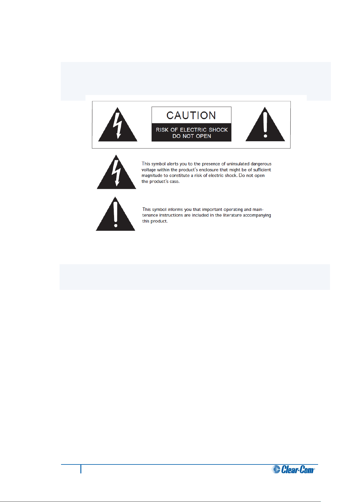
Safety symbols
Familiarize yourself with the safety symbols in Figure 1-1: Safety symbols. These symbols are
displayed on the apparatus and warn you of the potential danger of electric shock if the
system is used improperly. They also refer you to important operating and maintenance
instructions in the product user manual.
Figure 1-1: Safety symbols
Mains power cord
I-Series panels are powered by an external power supply. The cord to connect the external
power supply to the mains supply must conform to the following:
• The mains power cord shall have an IEC C13 connector at one end and a mains
power plug at the other end.
• An IEC C13 plug has three pins, the centre pin carrying the earth / ground. The
other two pins carry neutral and live circuits.
• The conductors of the mains cords shall have adequate cross-sectional area for
rated current consumption of the equipment.
• The mains plug that connects to the mains supply must be approved for use in the
country where the equipment is to be used.
• The mains power cord must be an IEC mains power cord complying with standard
IEC60320; IEC320/C13.
• Mains power cords used in the U.S. must also comply with standard UL817.
8
I-Series Panels User Guide
Page 9
I-Series user panel
Description / comments
2 Introduction
This guide describes how to install, use and maintain I-Series™ user panels from ClearCom®
I-Series user panels are fully compatible with both the Eclipse and Eclipse HX digital
matrix systems. Each panel is constructed from several individual units called modules,
which can be added or removed in the field. This enables you plan the panel’s initial
configuration and easily update the configuration as future operational needs change.
The standard configurations include 8, 16 or 32 key panels. Up to five E-1410E expansion
panels can be connected to a single I-Series user panel.
2.1 I-Series user panels covered by this guide
The following I-Series user panels are covered by this guide:
I-1110E user panel
I-1210E user panel
I-1410E user panel
I-1430E user panel
I-1470E user panel
E-1410E
Table 1: I-Series user panels covered by this guide
Table note:
Up to five E-1410E expansion panels can be connected to a single I-Series user panel.
2.2 Terminology
1x8-key display key module, no keypad.
2x8-key display key modules, no keypad.
4x8-key display key modules, no keypad.
4x8-key display key modules with keypad (both dial and
assignment menus).
As for the I-1430E, but with the AUX-101 module option (local
audio and GPIs).
4 x 8 display key extensi on pane l
In this guide, the term source refers to an intercom device (such as a user panel,
interface, or beltpack) that sends audio to your I-Series user panel. This audio from this
device represents a listen path to your user panel.
The term destination refers to a device to which you send audio. The audio sent to this
device represents a talk path from your user panel.
9
I-Series Panels User Guide
Page 10
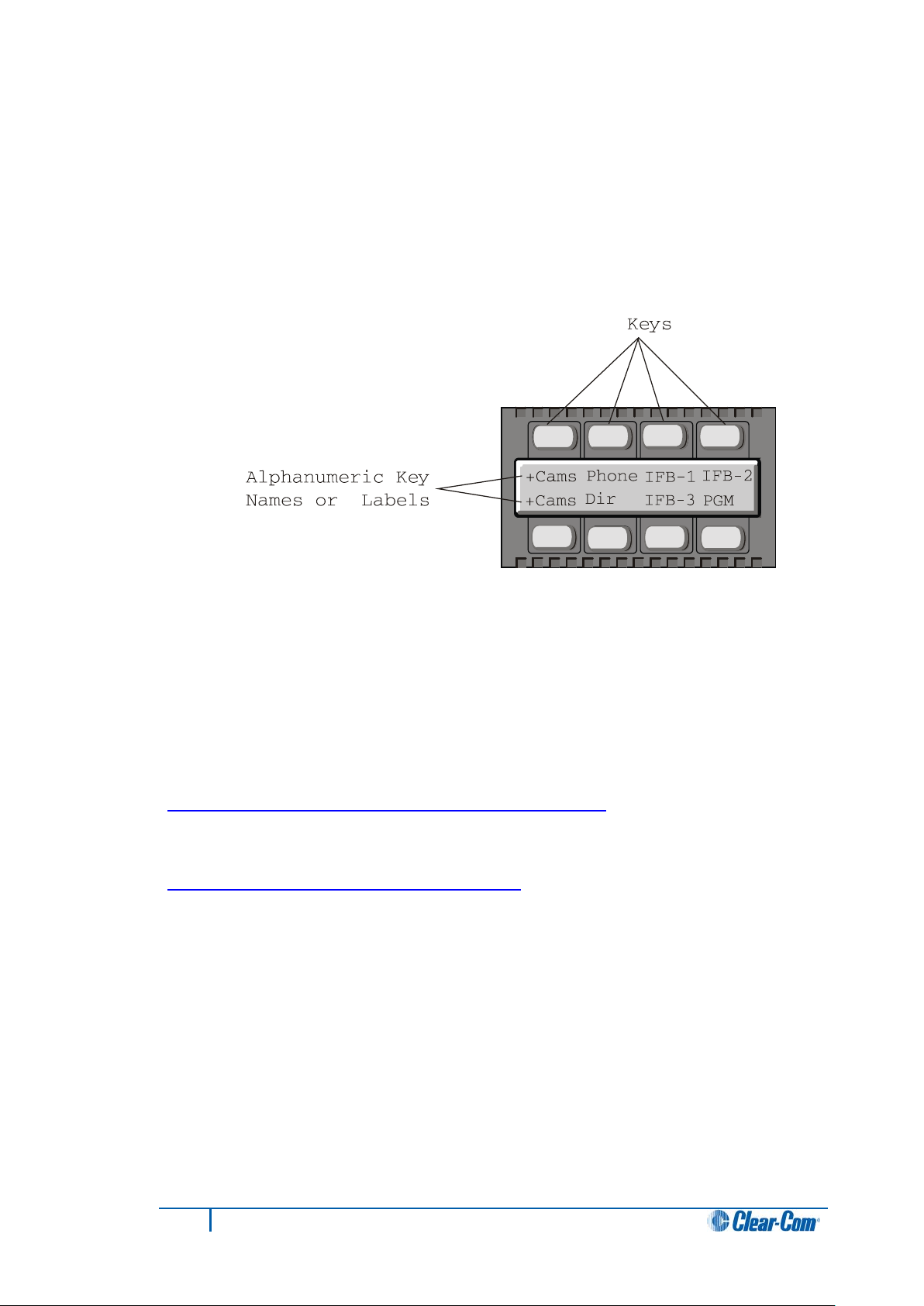
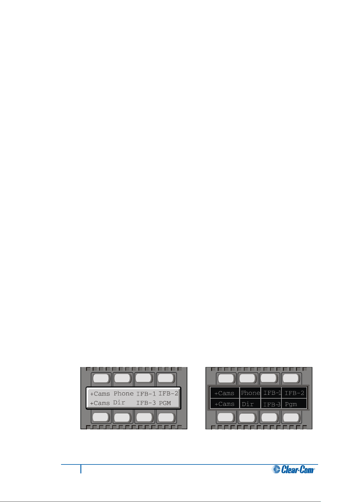
2.2.1 Labels
The names of the sources and destinations appear in the display of your user panel and
are called labels. A label is a 5-character alphanumeric name that identifies a source,
destination, or control function accessed by your user panel.
The label is displayed next to the key on the key module. The labels on the upper row refer
to the corresponding upper-row keys and the labels on the lower row refer to the
corresponding lower-row keys.
Figure 2-1: Labels on a key module
Note: Display modules have full-graphic LED-backlit displays that you program using the Eclipse
/ Eclipse HX configuration software (ECS / EHX). Non-display modules have metal
grooves into which paper labels can be inserted. Paper labels can be printed from ECS /
EHX.
2.3 Further information
I-Series documentation is available from your product CD-ROM. For more information
about the I-Series f amily of panels, see:
http://www.clearcom.com/product/digital-matrix/user-panel
For more information about the Eclipse and Eclipse HX digital matrix systems, referenced
by this guide, see:
http://www.clearcom.com/product/digital-matrix
.
For sales information, see your Clear-Com sales representative. For contact information
and legal disclaimers, see Page 2 of this guide.
10
I-Series Panels User Guide
Page 11

3 Overview
This chapter provides a brief overview of the I-Series family of user panels, including:
• Features.
• Chassis assembly.
• Modules (Key modules, Function Key modules, Mic-Headset modules, and Level-
Control modules).
• Standard panel configurations (I-1430E, I-1470E, I-111E, I-1410E, I-I210E and E1410E I-Series panels).
3.1 Features
I-Series panels incorporate a wide range of advanced features to enhance usability and
audio performance. The I-Series panels feature:
• Full graphic LED-backlit displays for each key.
• A 16-button keypad module for DTMF dialing and panel reprogramming
(I-1430E and I-1470E only).
• Adjustable, individual listen level.
• Auto-sensing headset and microphone connectors.
• Access to multiple audio sources and multiple speaker and headset inputs and
outputs when an auxiliary options module is installed (I-1470E only).
Tip: The auxiliary options module also provides you with two relays and two GPIs
(general-purpose inputs) that can be used either locally or system-wide.
• Advanced menu features, which enable you to perform the following tasks
(amongst others):
• Assign new destinations and sources to your panel directly from your panel.
• To program IFB sources and destinations.
• To dial telephone interfaces.
• To transform your panel into an assignment panel.
• To reset local volume levels.
11
I-Series Panels User Guide
Page 12
3.2 Chassis assembly
The chassis of the I-Series user panel is constructed of cold-rolled steel. The front-panel
modules and removable rack ears are cast from aluminum. All external connectors and
switches are structurally reinforced.
The keys feature long-life LED illumination, and the displays are full-graphic LCD with
long-life LED backlighting.
The internal architecture of I-Series panels is based on the Motorola M-Core processor. All
audio is digitized by CODECs and routed to a DSP that can be controlled as desired by
the user.
All I-Series user panels have internal power supplies.
3.3 Modules
I-Series user panels are designed in standardized units called modules.
Modules make it easier to add or remove components (such as keys) in the field, without
replacing the entire user panel. This makes upgrading (or repairing) panels easier, faster,
and less expensive.
Note:
For more information about using modules, see [put link here].
3.3.1 Key module
The key module is the basic building block of the I-Series user panel. A panel can host up
to four key modules.
The eight backlit keys in each key module are:
• Lit red to indicate talk status.
• Lit green to indicate listen status.
Each key has a 5-character alphanumeric display that shows its currently programmed
assignment. The alphanumeric name of an assignment is called a label.
ECS / EHX, the configuration software for Eclipse / Eclipse HX, is used to program the
labels for I-Series panels featuring backlit LCS displays.
User panels without display screens have slots for paper labels.
Figure 3-1: Key modules (electronic display on left, paper labels on
right)
12
I-Series Panels User Guide
Page 13
3.3.2 Function Key module
The function key module contains the panel’s basic and advanced controls.
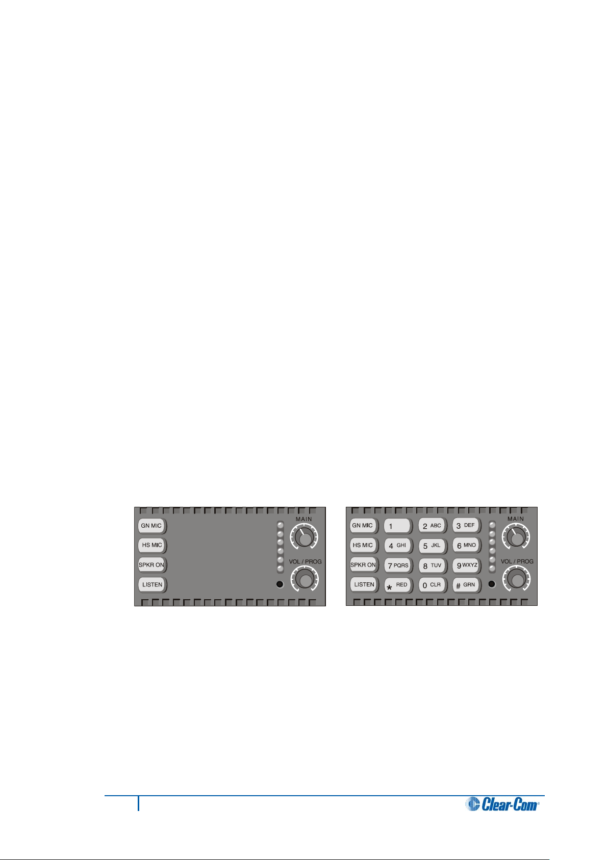
3.3.2.1 4-key module without numeric keypad
A 4-key function key module contains the keys that control basic intercom functions, such
as:
• Switching between gooseneck/headset speakers and microphones.
• Sending call signals.
• Adjusting listen levels.
The 4-key module has separate volume controls for intercom and program sources.
3.3.2.2 16-key module with numeri c keypad
The 16-key module includes the basic function keys and adds a 12-button numeric keypad
for dialing telephone interfaces and for programming advanced features. Advanced
features allow you to:
• Temporarily deactivate all latched keys on a panel.
• Override the on/off or volume settings at a destination.
• Assign new sources and destinations to your panel from your panel.
• Program IFB sources and destinations.
• Reset microphone and sidetone volume levels.
• Receive a variety of information about your panel on the panel’s LCD displays.
Figure 3-2: Function key modules (without keypad (left), and with keypad
(right))
13
I-Series Panels User Guide
Page 14
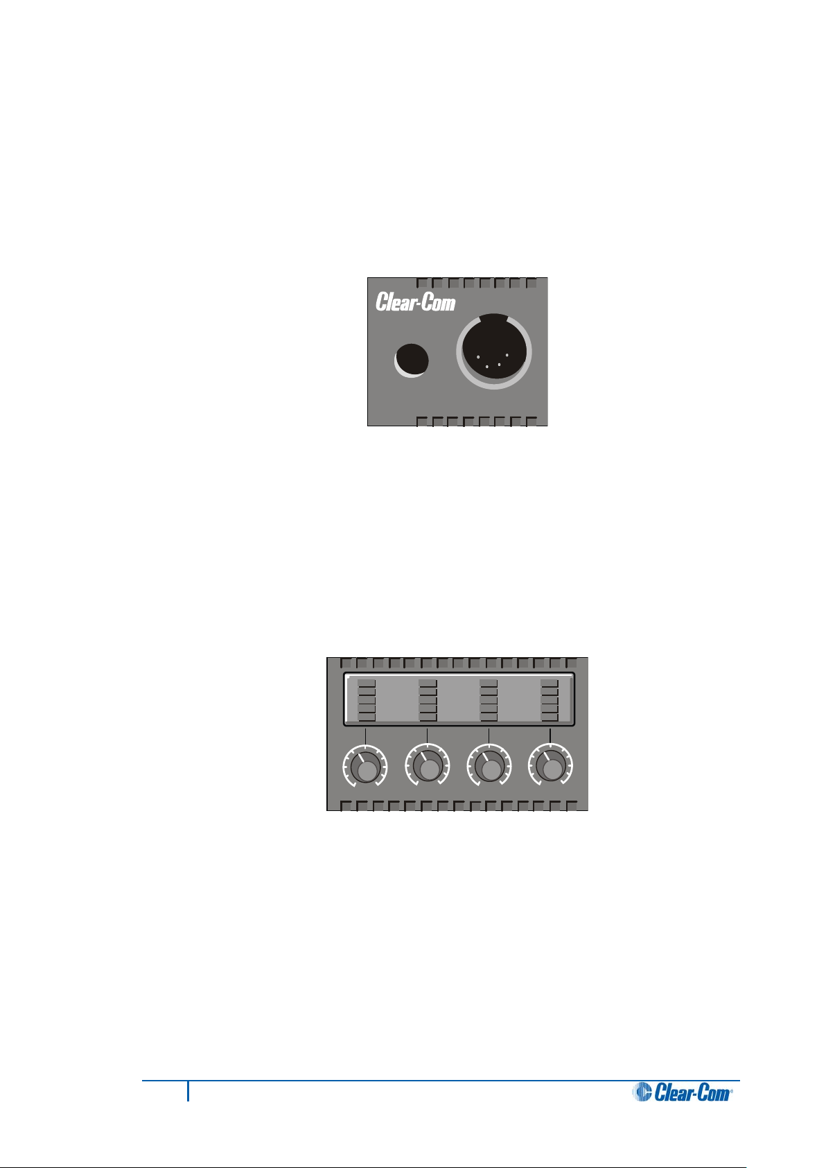
3.3.3 Mic-headset module
Every I-Series panel has a mic-headset module with:
• An auto-sensing headset and microphone connector.
• An integrated loudspeaker.
Figure 3-3: Mic-Headset module
3.3.4 Level control module
The level control module is used in conjunction with a key module to give you a constant
visual read-out of each key’s volume level.
Important note:
This option is no longer available for new sales but remains supported. For more
information, contact your Clear-Com sales representative.
Figure 3-4: Level control module
14
I-Series Panels User Guide
Page 15
3.3.5 AUX-101 auxi liary options module
The auxiliary options module connects your I-Series panel to a variety of audio and control
inputs and outputs.
Tip: This optional module can be installed in either the factory or the field, depending on
your requirements.
The AUX-101 module is located on the rear-panel of the I-Series chassis, and provides
the following functions:
• General purpose inputs.
• Relay outputs.
• Speaker-feed output.
• Line-level output.
• Hot-microphone output.
• Balanced-program input.
• Auxiliary microphone input.
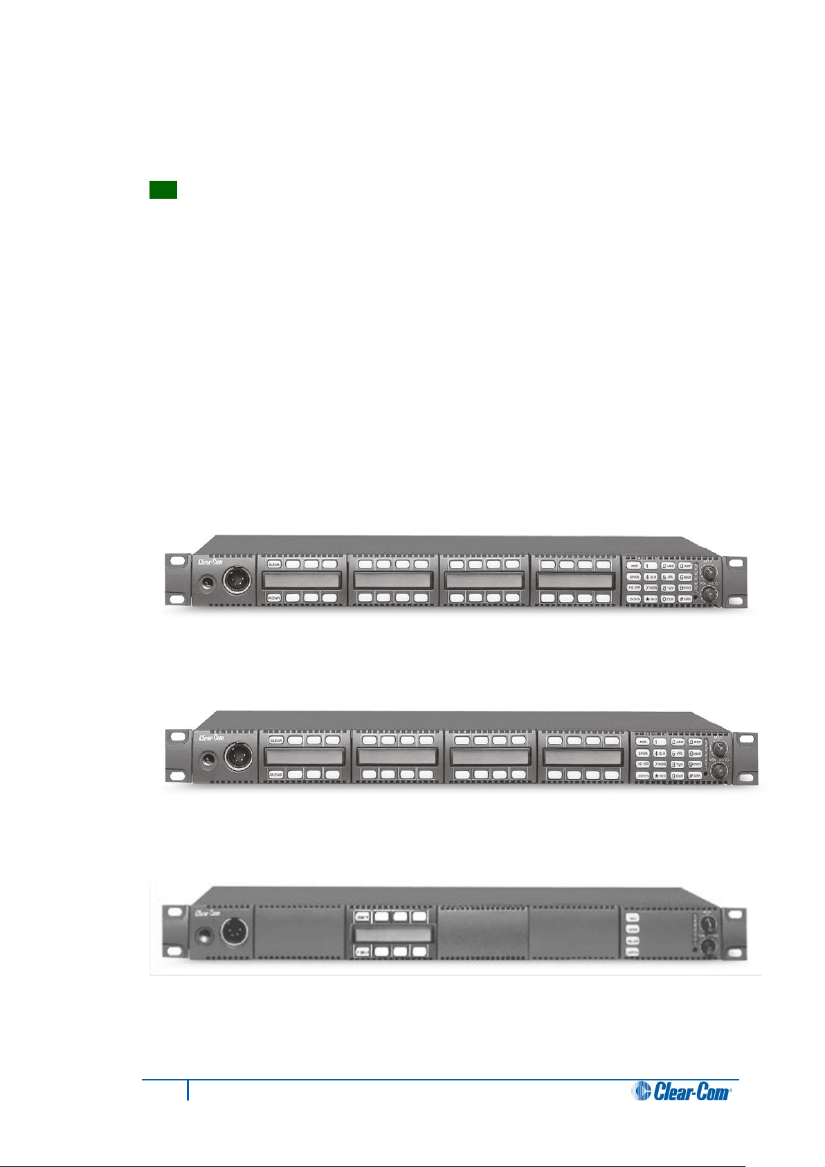
3.4 Standard I-Series user panel configurations
Figure 3-5
I-1430E 32 key I-Station Display with keypad
Figure 3-6
I-1470E 32 key I-Station Display + Aux-101 with keypad
15
Figure 3-7
I-1110E 8 key I-Station Display, no keypad
I-Series Panels User Guide
Page 16
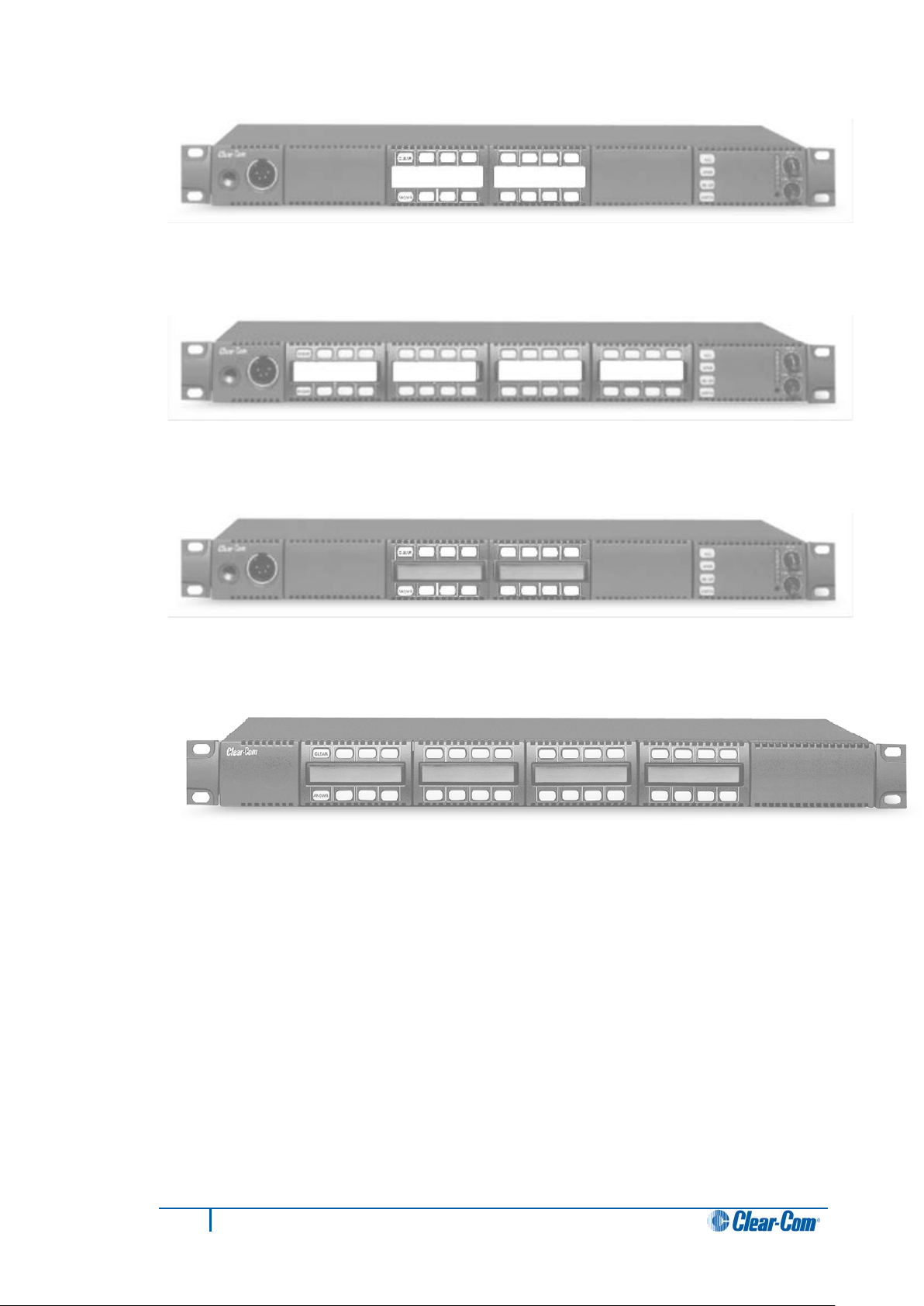
Figure 3-8
I-1200E 16 key I-Station, non-display, no keypad
Figure 3-9
I-1400E 32 key I-Station, non-display, no keypad
Figure 3-10
I-1210E 16-key I-Station Display, no keypad
Figure 3-11
E-1410E 32-key I-Station Display Extension
Note:
The I-1470E panel is the same as the I-1430E panel with the addition of a AUX-101 option
card fitted. The other main panels (but not the expansion panels) may also have the AUX101 option card fitted.
16
I-Series Panels User Guide
Page 17

4 Using I-Series panels
This chapter describes how to use the I-Series panels, including:
• Powering up I-Series panels.
• Front panel lights and controls.
• Key module lights.
• Answer-back (reply key) functionality.
• Volume controls.
• Upgrading I-Series panels.
Tip: For a brief description of all the 1-Series panels covered by this guide, including
product numbers, see
Table 1: I-Series user panels covered by this guide.
4.1 Powering up I-Series panels
4.1.1 Powering up panels with non-dis play key modules
When a panel with non-display key modules is connected to power, the keys on each key
module flash red, then green.
The keys then revert to their programmed colors (red for Talk or Talk-with-Listen, or
green for Listen).
Note:
If there is no communication with the Eclipse / Eclipse HX matrix, the keys will flash red
once per second until communication to the matrix is established.
4.1.2 Powering up panels with display key modules
When a panel with display key modules is connected to power, each of the display
modules will show the following message:
Clear-Com
Vx.x.x@2000
Where V.x.x.x represents the firmware version of the panel.
All keys will flash red, then green, and then display their programmed colors and labels if
there is communication with the matrix.
17
I-Series Panels User Guide
Page 18

If there is no communication to the matrix, the display will show the following message:
No connection to Eclipse.
The keys will then flash red four times per second until communication to the Eclipse /
Eclipse HX matrix is established.
4.1.3 Powering up panels with a func tion key module
When an I-Series panel is connected to power, all of the keys on the function key module
will flash red, then green, and then revert to their programmed colors if there is
communication with the matrix.
Note:
If there is no communication to the matrix, the keys will remain dark until communication is
established.
4.2 Front panel controls and lights
Each key on any key module can be assigned as a talk, a listen, or a talk-with-listen in
ECS / EHX, the configuration software for the Eclipse / Eclipse HX matrix system.
For more information, see the ECS User Guide / EHX User Guide.
4.2.1 Non-latching keys
If the key is non-latched, the key remains active for talk or listen for as long as you hold
down the key. Release the key to return the key to its non-active state.
4.2.2 Latching keys
Latching allows you to lock a key into place, so that you can talk or listen hands-free.
Quickly tap a key to latch it for talk or listen. The key will glow brightly to indicate that it is
active. The key will stay latched until you tap it again to return it to its non-active state.
4.2.3 Active and Non-Active Keys
When you activate a key (by pressing or latching the key to talk or listen) the key is lit:
• Bright red, for a talk or talk-with-listen key.
• Bright green, for a listen key.
The key lights up bright red while you talk to the destination. When you press or latch an
assigned listen key, the key lights up bright green while you listen to the source.
A key that is not active (that is, a key that is not being used to talk or listen) is lit:
• Dim red for a talk or talk-with-listen key.
• Dim green for a listen key.
18
I-Series Panels User Guide
Page 19

Key type
Active state
Inactive state
Talk
Bright red
Dim red
Listen
Bright green
Dim green
Talk with Listen Bright red, when pressed /
Table 2: Keys: active and inactive color coding
4.2.4 Alternative text key
The EHX software can cofigure an alternative text key called Show Alt Text to enable text
to change between normal text and alternate text.
The Show Alt Text key can be placed anywhere on the panel. This key can be placed on
all shift pages concurrently if desired to allow easy access.
When selected it will turn red, and the panel will show the alternate text.
Alias, VSM and PM text labels will override whichever state the panel is in.
One possible use of alternate text is to set up a dual language configuration on the panel,
for example to allow panels to display Arabic by default in a particular Middle Eastern
broadcast installation. English speakers could then select the Show Alt Text key on a
panel to see the English equivalents to the Arabic labels.
latched for talk.
Bright green, when pressed /
latched for listen
Dim red, when pressed /
latched for talk.
There is no non-active listen
mode. A talk with listen key
always reverts to non-active
talk.
Another use could be that both the role name and user name could be configured for each
panel or beltpack port. This would allow panel users to see either the name or the role
depending on the Alt Text mode selected.
4.3 Using keys to indicate status
A key can be programmed to light up in a variety of ways to indicate its status.
Note:
If you decide to use one of the following options, it must usually first be set up in ECS /
EHX, the configuration software for the Eclipse / Eclipse HX system.
4.3.1 Call waiting light (ANSWR key)
When a s ource ca lls an I-Series panel, the ANSWR key will flash bright red at the call
waiting rate (four times per second). The source will be displayed in the call waiting stack
above the ANSWR key.
Audio from the source can be heard at the I-Series panel.
Note:
If any other key on the panel is assigned to the source this key will also flash at the call
waiting rate.
19
I-Series Panels User Guide
Page 20

When you press the ANSWR key (or another key assigned to the source and flashing) to
talk, the ANSWR key and any other key assigned to the source stops flashing and is lit
bright red to indicate that the call is active.
When you release the key to take the call it becomes dim red to indicate that it is not
active.
Note:
Any other key associated with the call is also displayed dim red.
If a call is being answered when a second source calls you, the ANSWR key wil l not flash
at the call-waiting rate, but will continue to glow solidly bright red to indicate that:
• The key is active.
• The new call has been added to the call waiting stack on the ANSWR key.
If there is a key on the I-Series panel assigned to the source of the new call this will flash
bright red at the call rate. Audio from the stacked call will not be heard. Further calls will
also be added to the answerback stack until the limit of eight calls is reached.
To answer the second call, the first call must be terminated by releasing the key pressed
to answer the first call.
The first call will then be cleared from the call waiting stack when:
• The Answerback Auto Clear timeout threshold is reached.
• You press the CLEAR key.
The ANSWR key will then flash red at the call waiting rate to signal the next call is
waiting.
4.3.1.1 Answerback Auto Clear
The Answerback Auto Clear option sets the timeout before the current call is removed
from the answer-back stack, after the call has been ended. The Answerback Auto Clear
timeout option is set in ECS / EHX to a value between 1 – 60 seconds (or Off).
For more information, see the ECS / EHX User Guide.
4.3.2 In use light
A key will double-flash once per second to indicate that a destination you are trying to
call is in use.
The In-Use lig ht opt ion is set in ECS / EHX. For more information, see the ECS / EHX
User Guide.
4.3.3 Telephone off-hook light
A key will flash red once per second if a telephone interface is assigned to that key, and
the telephone interface is of f-hook. The Eclipse / Eclipse HX matrix will cause each key
assigned to the telephone interface on every panel in the system to flash at the off-hook
rate whenever the telephone interface module (TEL-14) is active (off-hook) at one or more
of the panels.
20
I-Series Panels User Guide
Page 21

If you press or latch a key that is flashing at the telephone off-hook rate, the key will glow
solidly bright red to indicate that the key is active. When you release the key, it will
resume flashing at the telephone off-hook rate.
The telephone off-hook light is set in ECS / EHX. For more information, see the ECS /
EHX User Guide.
4.3.4 Radio-receiver active light
The light on a key will flash red once per second if a radio receiver is assigned to that key,
and the radio receiver is active.
The Eclipse / Eclipse HX matrix will cause each key assigned to the radio receiver on
every panel in the system to flash at the radio-receiver active rate whenever the radio
receiver is active at one or more of the panels.
If you press or latch a key that is flashing at the radio-receiver active rate, the key will glow
solidly red to indicate that the key is active.
When you release the key, it will resume flashing at the radio-receiver active rate.
The radio-receiver active light requires:
• That the radio receiver is connected using a FOR-22 interface module.
• Enabling in ECS / EHX, in the Advanced Settings > Tallies options for the FOR-
22 interface module.
For more information, see the ECS / EHX User Guide.
4.3.5 Panel connected light
When the Station Connected Tally option is selected in ECS / EHX (under Advanced
Settings > Global Settings), the key assigned to a destination panel will flash red once
per second on your user panel, whenever that destination panel is connected to the
Eclipse / Eclipse HX matrix.
The Station Connected Tally is set up in ECS / EHX. For more information, see the ECS /
EHX User Guide.
Note:
This option is primarily used when a destination panel is connected to the matrix using a
long-line link that might be active only at certain times.
4.3.6 Audio-presence light
If you assign a source to your panel as a listen-only key, the key will flash green once per
second if there is audio present at the source.
The audio-presence light is set up in ECS / EHX. For more information, see the ECS /
EHX User Guide.
21
I-Series Panels User Guide
Page 22
Module key
Light color
Blink rate
Listen-only key (inactive)
Dim green
None (solid)
(inactive)
Listen-only key (active)
Bright green
None (solid)
Talk key (active)
Bright red
None (solid)
Talk with Listen key (active)
Call waiting
Bright red
4 x per second
In use
Dim red
2 x per second
Audio presence
Dim green
1 x per second
Panel connected
Dim red
1 x per second
Telephone off-hook
Dim red
1 x per second
Radio receiver active
Dim green
1 x per second
Incompatible firmware
Bright red
1 x per second
4.3.7 Incompatible firmware light
If the firmware on your panel is incompatible with the matrix, all lights on the panel will
blink dim red once per second.
The display shows the following message:
No connection to Eclipse.
4.4 Key module lights (summary)
Talk or Talk with listen key
Listen component only of
Table 3: Key module lights (summary)
Dim red None (solid)
Bright green
4.5 Answer-back (ANSWR)
None (solid)
With the answer-back feature you can reply to incoming calls from sources not assigned
to keys on your I-Series panel. You can also call out to destinations not assigned to keys
on your panel.
Tip: The answer-back feature is known as the Reply key on V-Series panels.
If a second unassigned source calls you while you are speaking to the first unassigned
source, the second call is placed in the answer-back stack, a group of up to eight waiting
calls that are answered in sequence.
All incoming calls can be answered at the answer-back keys, whether from sources with
assigned keys on the intercom panel or from sources without assigned keys. Typically,
however, only calls from sources without assigned keys are answered there.
The following sections describe how to use the answer-back feature.
22
I-Series Panels User Guide
Page 23
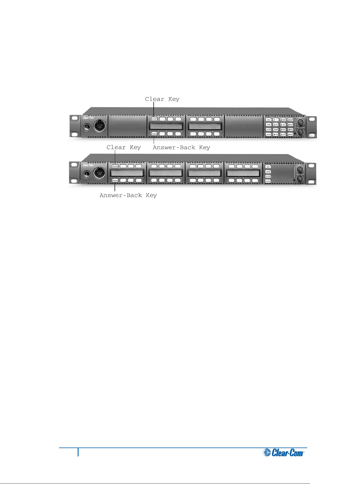
4.5.1 Using the Answer-back (ANSWR) and Clear (CLEAR) keys
The Answer-back key (ANSWR) is the leftmost lower key on your I-Series panel. The
Clear key (CLEAR) is the leftmost upper key on your I-Series panel.
Figure 4-1: Answer-Back (ANSWR) and Clear (CLEAR) keys
To answer a call with the Answer-back (ANSWR) key, when a source that is not assigned
to a key on your panel calls you, press the ANSWR key when:
• The calling source’s label appears in the display above the ANSWR key.
• The ANSWR key flashes bright red to indicate a waiting call.
If you do not press the ANSWR key, the answer-back time-out period lapses and the call is
automatically removed from the answer-ba ck stack.
Note:
The answer-back time-out peri od is set in ECS / EHX. It can be set to Off or between 10 60 seconds. After the time-out period has elapsed, the call will be removed and will no
longer be available to answer.
To answer a call from an unassigned source at the Answer-back (ANSWR) key:
1. Press and hold the ANSWR key to t alk to the caller. The key is lit solid red to
indicate that it is active.
Note:
The ANSWR key cannot be latched.
2. When you complete the call, release the ANSWR key. The key is lit dim red to
indicate that it is inactive.
3. Press the CLEAR key to remove the caller’s label from the display.
Note:
The display clears automatically when the answer-back time-out period elapses
after you release the ANSWR key.
23
I-Series Panels User Guide
Page 24
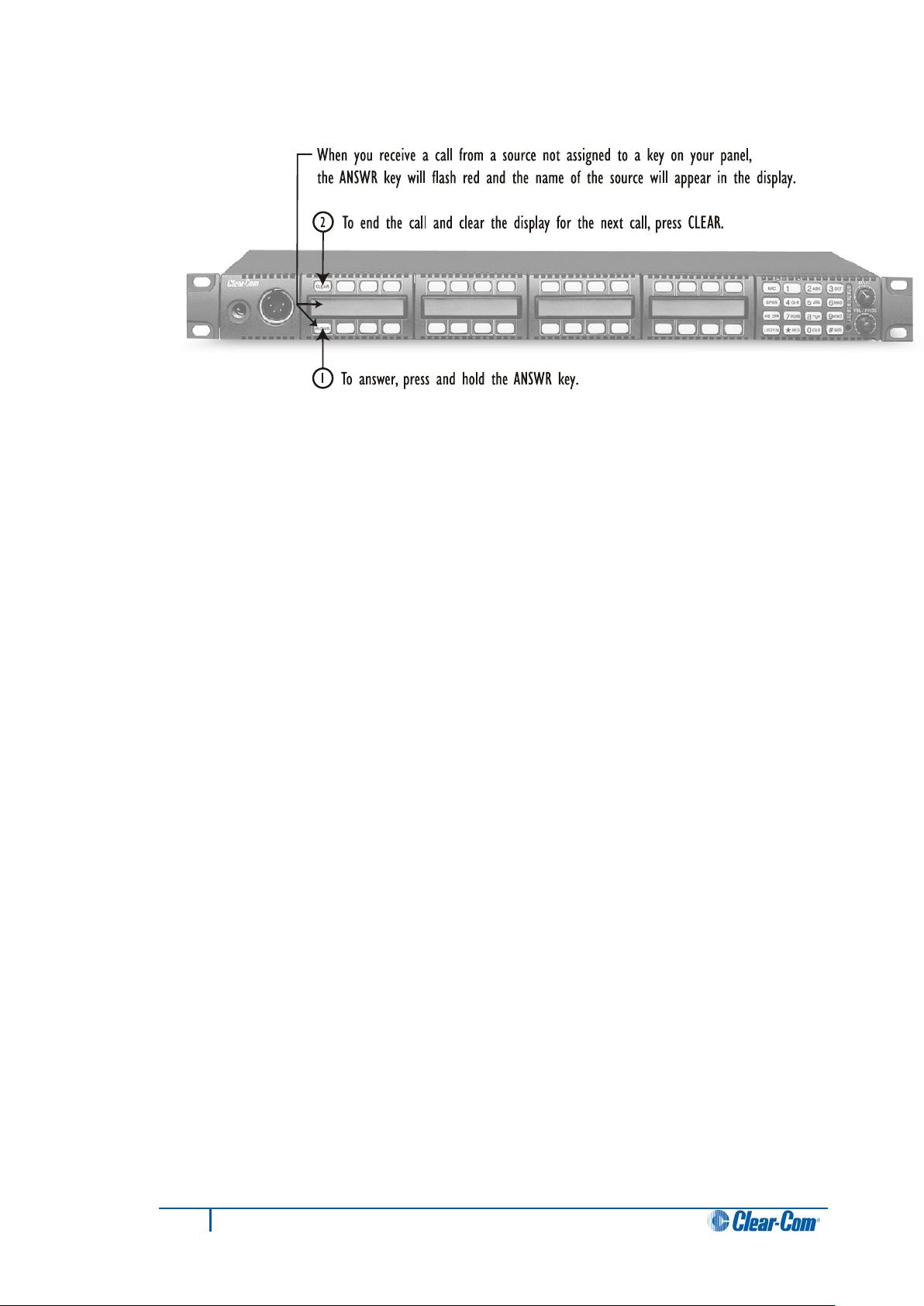
Figure 4-2: Answering a call from an unassigned caller
If a second unassigned source calls you while you are talking to the first unassigned
source:
• The second caller’s audio will come through on your panel’s speaker.
• The second call will be placed in the Answer-back stack (a call list of up to eight
possible waiting calls).
• The second caller’s label will appear directly above the current caller’s label. The
current caller’s label appears in the display directly above the ANSWR key.
The light on the ANSWR key will flash red, at the call-waiting rate (see above), to show
that a call is waiting and that a call is currently in progress.
Note:
The ANSWR key flashes between bright red–dim red instead of the usual bright red–off,
to show that a call is also currently in progress.
To answer a call waiting in the answer-back stack:
1. Press and hold the ANSWR key to speak to the caller.
The new caller’s label will appear in the position directly above the ANSWR key,
while the next waiting call (if there is one) will display in the position directly above
it. A total of eight calls can wait in the answer-back stack.
Note:
Only the two most recent caller’s labels will appear in the display above the
ANSWR key.
2. When you complete the call, release the ANSWR key.
3. Press the CLEAR key to remove the caller’s label from the display.
The next unassigned caller’s label appears in the display above the ANSWR key.
Note:
The display clears automatically when the answer-back time-out period elapses
after you release the ANSWR key.
4. When the next caller’s label appears above the ANSWR key, press the ANSWR
key to talk to the caller.
5. Repeat steps 2 and 3 until all the calls in the Answer-back stack are answered.
24
I-Series Panels User Guide
Page 25
ANSWR key
Light color
Blink rate
No calls at Answer-back
Off
N / A
back
pressed
CLEAR key
Light color
Blink rate
No calls at Answer-back
Off
N / A
empty
4.5.2 Answer-back (ANSWR) and Clear (CLEAR) key lights (summary)
Calls received at Answer-
Answer-back (ANSWR) key
Answer-back stack not
Clear (CLEAR) key pressed Bright green
Table 4: Answer-back (ANSWR) and Clear (CLEAR) key lights (summary)
Bright red
Dim red None (solid)
Dim green None (solid)
4.6 Speaker and headset volume controls
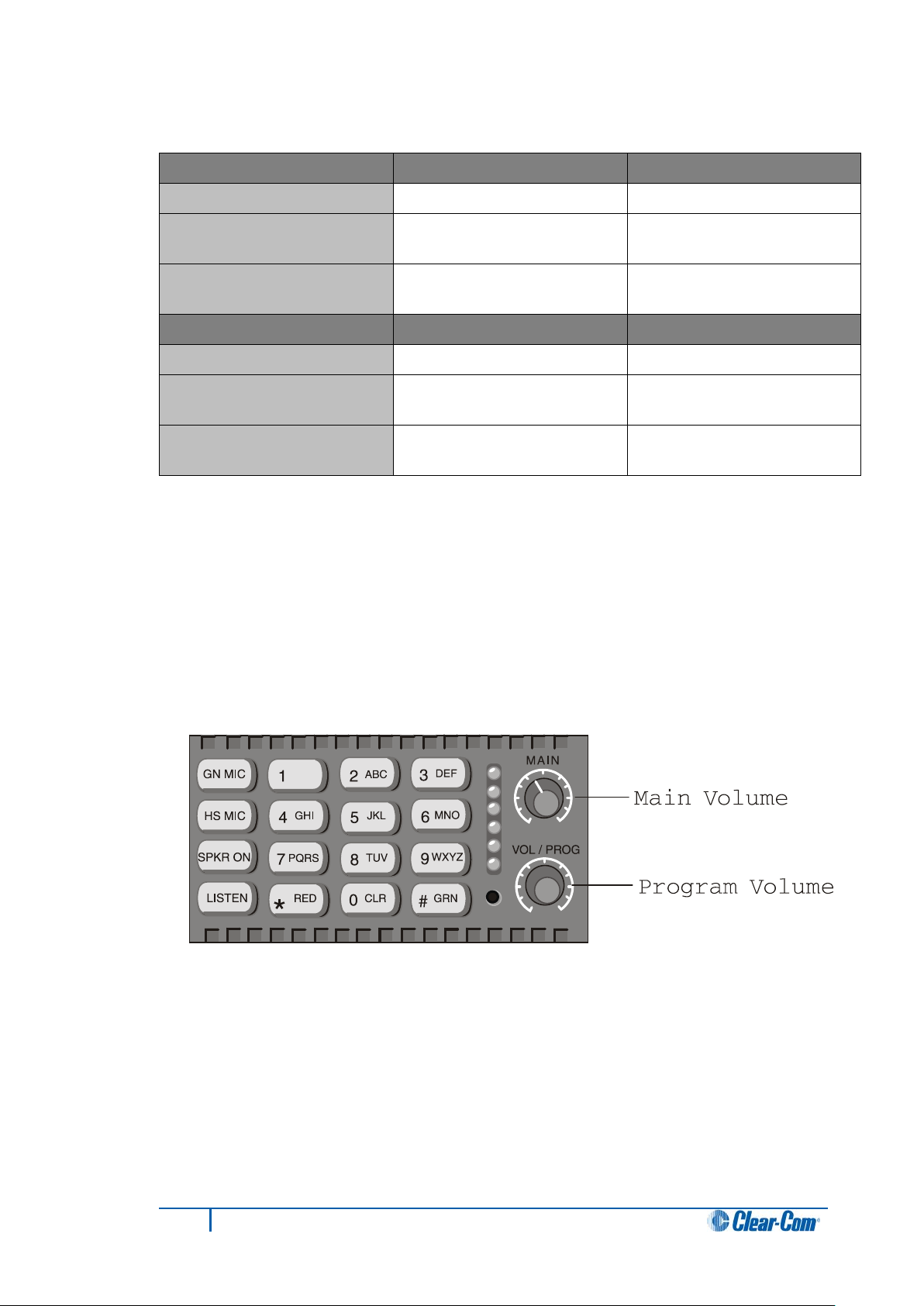
4.6.1 Adjusting the main volume
The master volume level on your panel’s speaker and headset is adjusted using the main
volume control on the function key module.
4 x second
None (solid)
Turn the control clockwise to increase the volume, counterclockwise to decrease it.
Figure 4-3: Main volume and program input volume contro ls
25
I-Series Panels User Guide
Page 26

4.6.2 Adjusting the program input volume
Important note:
You receive program input at your panel through the AUX-101 auxiliary options module.
The AUX-101 module must be installed to the panel before you can adjust the program
input.
You adjust the program input volume on your panel’s speaker and headset using the
program input volume control (VOL/PROG) on the function key module.
Turn the knob clockwise to increase the volume, counterclockwise to decrease it.
4.6.2.1 Program input volume lights
The six LEDs located to the left of the program volume knob indicate the program volume
level. As the volume goes up or down, the number of LEDs that are lit changes.
Minimum volume is indicated by one illuminated LED. The maximum volume is indicated
by six illuminated LEDs.
You control the brightness of the six-segment LED with the Display Brightness settings in
ECS / EHX. For more information, see the ECS / EHX User Guide.
Tip: You can also use the program volume knob to adjust listen levels, to scroll through
menu items, and to select menu items. These functions are discussed later in this chapter.
4.6.3 Adjusting listen levels
When you are required to monitor several incoming sources at once, you can vary the
volume of the sources by setting the listen levels.
For example, in a control room you may be listening simultaneously to the lighting
department, the sound department, and the tape editing department, but because you
need to cue the director when the show is ready to go on the air, listening to the tape
editing department takes highest priority. You need to adjust the volumes (the listen levels)
of the monitored sources so that the tape editing department is louder than the others.
4.6.3.1 Method 1
To adjust the listen level of an incoming source:
1. Press the desired listen key. The liste n key is lit bright green.
2. Press and release the VOL/PROG control. The listen key flashes dim green.
3. Press and release the listen key again. The listen key is lit bright green.
4. To increase the source’s volume (listen level), turn the VOL/PROG control
clockwise.
To decrease the source’s volume (listen level), turn the VOL/PROG control
counterclockwise.
26
I-Series Panels User Guide
Page 27

5. When the required volume has been reached, press and release the VOL/PROG
control to accept the setting.
6. Press and release the listen key. The source’s volume (listen level) is now set at
the required level.
Note:
If you try to push an active listen path higher than the maximum possible volume, you will
drive the volume of all other active paths downward, putting more emphasis on the desired
path.
4.6.3.2 Method 2
The listen levels may also be adjusted using the Local Preferences menu (requires a 16button key module).This method only works with a 16-button function key module.
To adjust the listen levels, using the Local Preferences menu:
1. To display a list of menu items, press the Enter key (labeled #GRN) on the
numeric keypad.
2. The top two menu options are displayed in the panel’s leftmost display. Scroll to
Local Preferences, using the VOL/PROG control.
To select Local Preferences, press the VOL/PROG control or press 7 on the
numeric keypad.
Tip: You can also scroll through the menu items one at a time by pressing the
CLEAR key to scroll up the menu and the ANSWR key to scroll down the menu.
3. In Local Preferences, scroll to Listen Level Adjust.
To select Listen Level Adjust, press the VOL/PROG control or press 5 on the
numeric keypad.
Listen Level is displayed in the panel’s leftmost display, indicating that you are in
listen-level-adjust mode.
Tip: To quickly enter Listen Level Adjust mode, simply press three keys in quick
succession: the Enter key (labeled #GRN), followed by the 7 key, followed by the 5
key.
4. Tap any listen key or talk-with-listen key to select it. The key is lit bright green.
5. Rotate the VOL/PROG knob clockwise to increase the source’s volume or
counterclockwise to decrease the source’s volume.
6. Continue adjusting listen levels by first tapping a key to select it, and then rotating
the VOL/PROG knob to adjust the source’s volume.
7. To exit Listen Level Adjust mode, press the Escape key (labeled *RED).
Tip: You can also exit listen-level-adjust mode by not pressing a key on the
numeric keypad (0–9, *, #) for five seconds. After five seconds the mode times out.
27
I-Series Panels User Guide
Page 28

4.6.3.3 Method 3
To adjust the listen level of an incoming s ource:
1. A key lit bright green indicates an incoming listen source. To adjust the listen level
(volume), press 1 on the numeric keypad.
2. Turn the VOL/PROG control clockwise to increase the source’s listen level
(volume) or counterclockwise to decrease the source’s listen level (volume).
4.6.4 Resetting listen levels to the default level
You can reset all listen levels to the default, which is the highest possible volume. To reset
all listen keys back to the default level:
1. Enter Local Preferences mode by pressing the 7 key on the numeric keypad.
2. The display on the leftmost key module shows the first two items in a list of local
preferences. Scroll to Reset Listen Levels by turning the VOL/PROG control.
Select Reset Listen Levels by pressing the VOL/PROG control. The listen levels
are reset to their default level (the highest possible volume) and the display reads:
Listen Level Reset Sent to Matrix.
Tip: You can also scroll through the list one item at a time by pressing the CLEAR
key to scroll up the list and the ANSWR key to scroll down the list.
All listen keys are now reset to the default (the highest possible volume).
Note:
When you activate a listen key at your panel, audio will come in at the default level.
If a caller sends audio to you, that audio will come into your panel at the highest
possible volume.
4.7 Upgrading the I-Series panel firmware
Caution: When a firmware updgrade to an I-Station has started, wait for
it to complete on all panels before doing any other changes to the
matrix.
To upgrade the I -Series panel firmware:
1. Download the I-Series firmware upgrade to the Eclipse / Eclipse HX matrix from
ECS / EHX.
2. Provided that the Panel Prompt option is set, the I-Series panel displays the
following message:
28
I-Series Panels User Guide
Page 29

UPGRD TO VER nnnnn YES NO
Each word corresponds to a key on the panel, and nnnnn represents the firmware
upgrade number.
The I-Series panel keys flash, indicating that an upgrade is available.
Note:
The prompt is displayed provided that the I-Series panel is online.
3. To decline the upgrade, the I-Series user presses the NO key (right-hand flashing).
The I-Series panel returns to its normal display. If the upgrade is declined it will not
be offered again until a black reset is performed on the matrix.
To accept the upgrade, the I-Series user:
a. Presses the YES key (left-hand flashing). The I-Series panel displays the
following:
ARE YOU SURE nnnnn YES NO.
Each word corresponds to a key on the panel, and nnnnn represents the
firmware upgrade number.
b. If the user selects the NO key, the upgrade is cancelled and will not be
offered again until a black reset is performed on the matrix.
If the user selects the YES key, the firmware upgrade is applied to the I-
Series panel.
29
I-Series Panels User Guide
Page 30

Key to Figure 16: Four basic function keys, function module
Call-out
Key
Description
A
B
C
D
JKL
5
HS MIC
SPKR ON
LISTEN
*
RED
PQRS
7
CLR
0
TUV
8
GN MIC
4
GHI
1
ABC
2
VOL / PROG
GRN
#
WXYZ
9
6
MNO
DEF
3
MAI N
A
B
C
D
5 Using the basic function keys
The four basic function keys provide convenient one-touch access to such basic intercom
functions as turning the microphone on and off.
Tip: For a brief description of all the I-Series panels covered by this guide, see
Table 1: I-Series user panels covered by this guide.
5.1 The four basic function keys
Figure 5-1: Four basic function keys, function module
GN MIC
HS MIC
SPKR ON
LISTEN
Table 5: Key to Figure 16: Four basic function keys, function module
Gooseneck microphone on/off
Headset microphone on/off.
Speaker on/off.
Listen-only, call signaling and remote telephone release functions
30
I-Series Panels User Guide
Page 31

5.2 Turning the gooseneck micr o ph one on and off
The gooseneck microphone key (GN MIC) on the function module turn s your panel’s
gooseneck microphone on or off.
Press once to turn the microphone on. Press again to turn the microphone off.
If you press a talk key while the gooseneck microphone is plugged in but off, the
gooseneck microphone automatically turns on for the duration of the call.
The GN MIC key is lit:
• Dim green whenever the gooseneck microphone is present but off.
• Bright green whenever the microphone is present and on.
If a gooseneck microphone is not present, the GN MIC key will not be lit.
5.2.1 Switching from the gooseneck mi c rophone t o t he he a ds e t
The gooseneck microphone is your panel’s default microphone unless a headset is
connected.
When a headset is connected, an auto-sensing circuit in the panel automatically turns the
headset microphone on and turns the gooseneck microphone off. The headset
microphone always takes precedence over the gooseneck microphone.
5.3 Turning the headset micro ph on e on and off
The headset microphone key (HS MIC) turns your panel’s headset microphone on and off.
Press once to turn the microphone on. Press again to turn the microphone off.
The HS MIC key is lit:
• Dim green whenever a headset microphone is present but off.
• Bright green whenever a headset microphone is present and on.
When a headset microphone is not present, the key will not illuminate.
5.3.1 Switching from the headset t o the goosenec k m icrophone
When a headset is connected to the panel, the headset microphone automatically
becomes active and the gooseneck microphone is switched off. To switch to the
gooseneck microphone, press the gooseneck microphone key (GN MIC). When the
headset is disconnected, the gooseneck microphone automatically becomes active.
31
I-Series Panels User Guide
Page 32

5.4 Turning the speaker on and off
The speaker on/off key (SPKR ON) only functions when a headset is connected to the
panel.
Press the key once to turn the headset speaker off, and again to turn the headset speaker
back on.
Note:
When the headset speaker turns off, the panel speaker will turn on and vice versa.
The SPKR ON key is lit:
• Dim green when the headset speaker is off.
• Bright green when the headset speaker is on.
Unlike the microphones, you cannot turn off both speakers (the panel and the headset
speaker) at the same time. The panel loudspeaker is always active unless a headset or
alternative speaker source has replaced it.
Note:
The SPKR ON key is non-functional when a headset is not connected.
5.5 Using the Listen (LISTEN) key
You can use the Listen (LISTEN) key to:
• Place a talk-with-listen key in monitor mode.
• Send call signals.
• Release remote telephone lines.
Figure 5-2: The three functions of the LISTEN key
32
I-Series Panels User Guide
Page 33

5.5.1 Placing a talk-with-listen key in monitor mode
Monitor mode enables you to momentarily change the status of a key from listen-only to
talk-with-listen. By pressing and holding the listen-only key, you momentarily change it to
a talk-with-listen key.
To activate the monitor mode of a t alk-with-listen key:
1. Press the LISTEN key on the function key module for less than one second (tap
the key). The LISTEN key is lit bright green.
To indicate that its monitor mode is available for activation, each talk-with-listen
key is lit dim green.
2. To place a talk-with-listen key in monitor mode, press (tap) a dim-green key.
To indicate its change to an active listen-only key, the key is lit bright green.
3. To talk to the source, press and hold the key.
To indicate that a talk-with-listen call is act ive, the key is lit bright red. When you
release the key, it reverts back to its active listen-only mode (bright gr een).
Note:
The talk-with-listen function cannot be latched, and is only active while you press
the key.
To cancel the key’s monitor mode and revert back to talk-with-listen mode:
1. Press (tap) the LISTEN key on the function-key module.
2. Tap the desired active listen-only key (bright green).
The formerly active listen-only key is now lit dim red to indicate that it has reverted
back to its non-active talk-with-listen mode. If you press the key to talk, it is lit
bright red.
Note:
You must tap the LISTEN key on the function key module for each key you activate
in monitor mode.
5.5.2 Sending call signals
A call signal is an electronic signal that is sent from one user panel or interface to another
to:
• Get a panel operator’s attention.
• Activate a relay (for example, to open a door, set off an alarm, or activate a public
address (PA) system).
33
I-Series Panels User Guide
Page 34

Tip: To use call tones, call tones must be enabled for the destination user panel or
interface in ECS / EHX. For more information, see the ECS / EHX User Guide.
To send a call signal:
1. Press and hold the LISTEN key for between 1 and 5 seconds. To indicate that you
have entered call-signal send mode, the LISTEN key is lit bright red.
2. Press the key of the destination that you want to send the call signal to.
A call signal of three loud beeps is sent to the destination every time that you
press the destination’s key.
3. Repeat step 2 for any other destination you want to send a call signal to.
4. To exit call-signal send mode, press (tap) the LISTEN key and release.
Tip: You can also exit call-signal send mode by simply not pressing a display key
for five seconds. The mode will automatically time-out.
5. On exiting call-signal send mode, the LISTEN key changes from bright red to no
illumination.
Sending a call signal to multiple destinations
You can send a call signal to any destination with a designated key on your panel. If more
than one destination is assigned to a key, each destination will receive the call signal. If
the destination is a partyline, then every panel listening on the partyline will receive the call
signal.
Note:
The call signal is sent at the page-override volume level, which you set in ECS / EHX. For
more information, see the ECS / EHX User Guide.
5.5.3 Releasing remote telephone lines
To release a telephone interface that has been left off-hook with the LISTEN key:
1. Enable remote telephone release for the panel in ECS/EHX.
Tip: Often this feature will already be set up in ECS/EHX. For more information,
see the ECS/EHX User Guide.
2. Press and hold the LISTEN key for more than 5 seconds. The LISTEN key turns
bright green and flashes on and off.
3. While still holding the LISTEN key, press the desired telephone interface key on
any key module.
The telephone interface will hang up. All audio paths to and from the telephone
interface will be deactivated.
4. Release the LISTEN key to exit.
34
I-Series Panels User Guide
Page 35

Basic function key
Light color
Blink rate
GN MIC key
Gooseneck microphone off
Dim green
None (solid)
Gooseneck microphone on
Bright green
None (solid)
HS MIC key
Headset not present
Not lit (off)
None
Headset present and off
Dim green
None (solid)
Headset present and on
Bright green
None (solid)
SPKR key
Speaker on
Dim green
None (solid)
Speaker off
Bright green
None (solid)
LISTEN key
No function
Not lit (off)
None
Listen-only call mode
Bright green
None (solid)
Call-signal send mode
Bright red
None (solid)
Remote telephone hang-up
Bright green
1 x second
0–9, *, # Keys
No function
Not lit (off)
None
Key pressed or mode active
Bright green
None (solid)
Dial mode
Dim red
None (solid)
Dial mode and key pressed
Bright red
None (solid)
5.6 Function key module lights (summary)
Table 6: Function key module lights (summary)
35
I-Series Panels User Guide
Page 36

6 Using the advanced features
This chapter describes the advanced features of the I-Ser ies panels, including
assignments (local key, IFB, partyline and Fixed Group assignments) and local system
settings (Local Preferences).
Most of the advanced features on I-Series panels are only available when the panel is
connected to the Eclipse / Eclipse HX matrix.
6.1 Accessing advanced features
I-Series user panels have advanced features that you can access by either:
• Pressing the number key associated with the feature. For example, when you
press 1 on the numeric keypad, you enter telephone dialing mode.
• Scrolling through the feature menu. For example, you can access telephone
dialing mode by selecting Dial in the feature menu. The advantage of a menu is
that you do not have to memorize each available key function. See “Selecting
Features from the Menu” later in this chapter for more information.
Figure 6-1: Advanced features, accessed from the numeric keypad
36
I-Series Panels User Guide
Page 37

Key
Feature
Description
1
Dial
Activates telephone dialing mode
that is currently being used.
destination.
Assignments
Assignments
to keys on your user panel.
page on the user panel.
Level Adjust.
card (on the matrix), and current firmware version number.
previous menu.
to normal use.
panel to normal use.
Baud Rate Adjust
6.1.1 Advance features accessed by the numeric keypad (summary)
2 Local Exclusive
3 Local Page Override
4 IFB, Partyline and
Fixed Group
5 Local Key
6 Swap Page
7 Local Preferences Enables you to adjust Listen Level Reset, Panel Mic
9 Port Information
0 CLR Clear
*RED Escape or Cancel
Mode temporarily deactivates all keys except for the one
Mode overrides current on/off and volume settings at a
Mode enables sources to be assigned to IFBs, partylines
and Fixed groups.
Mode enables the assignment of sources and destinations
Enables you to switch between the main page and the swap
Level, Headset Mic Level, Sidetone Level and Listen
Comprises the panel’s port number, label, associated CPU
Clears the current display entry and takes you back to the
Abandons all unsaved programming and returns the panel
#GRN Enter
VOL/PROG Display Contrast
Adjust
Table 7: Advanced features, accessed by the numeric key pad (Summary)
Saves the current programming changes and reverts the
Allows you to adjust contrast lighting on displays and to
adjust the panel’s baud rate.
6.2 Telephone dialing from the keypad (#1 key)
You can dial from the keypad on a function key module as if you were dialing from a
standard telephone keypad.
When you press the number keys, standard DTMF tones are generated to all active talk
key destinations. Note that this feature is only available when the central matrix is
connected and online.
37
I-Series Panels User Guide
Page 38

To generate standard DTMF tones to all active talk key destinations:
1. Enter dialing mode by pressing the 1 key on the keypad. The keypad becomes a
telephone touch-tone dialing pad.
Note:
The word Dial appears in the display below the Clear (CLEAR) key.
2. All 12 valid dialing keys on the keypad are lit dim red. Press keys on the numeric
keypad (0–9, *, #) to generate standard DTMF tones to all active talk-key
destinations.
3. To exit dialing mode, press th e CLEAR key.
Tip: Dialing mode automatically times out if you do not press a key on the numeric
keypad (0–9, *, #) for five seconds.
6.3 Accessing Local Exclusive (#2 key)
In Local Exclusive mode, all previously latched keys on your panel deactivate temporarily
while you talk exclusively to one destination or listen to one source.
Note:
Local Exclusive is only available when the Eclipse / Eclipse HX matrix is connected and
online.
To use Local Exclusive mode:
1. Enter Local Exclusive mode by pressing the 2 key on the keypad.
2. Press and release any talk or listen key (even an already latched key).
When you press and release a talk or listen key, all previously latched keys (both
talks and listens) deactivate temporarily, and you can talk or listen from that key
exclusively.
Note:
The feature is only active while the key is latched in Local Exclusive mode. The 2
key on the keypad is lit bright green while this feature is active.
3. To exit Local Exclusive mode, press the key you pressed in step 2 again to
deactivate it.
The previously latched keys return to their active state.
Note:
The Local Exclusive feature does not work with the answer-back (ANSWR) key.
6.4 Local Page Override (#3 key)
Local Page Override you to talk to one or more destination panels regardless of the on/off
or volume settings at each panel’s speaker. The feature overrides the current on/off and
volume settings at the destination.
Tip: You can adjust the local page override’s volume level in ECS / EHX. By default, the
volume is set up at 5 on a 1–10 scale, but it can be adjusted to any value on the scale.
38
I-Series Panels User Guide
Page 39

Note:
Local Page Override is only available when the Eclipse / Eclipse HX matrix is connected
and online.
To activate Local Page Override:
1. To ent er Local Page Override mode, press 3 on the keypad.
2. Press any talk key (even an already latched key).
You can now talk to all destinations associated with that key. The current on/off
settings and volume levels are overridden at those panels’ speakers.
Note:
The Local Page Override feature does not work with the answer-back (ANSWR)
key. The 3 key on the keypad is lit bright green while this feature is active.
If a key cannot be page overridden because it is assigned as an interface or
partyline, there will not be an error message to indicate that the function is not
available on that key.
3. To exit Local Page Override, release the pressed talk key.
Tip: Local Page Override mode automatically times out if you do not press a key
on the function-key module for five seconds.
6.5 IFB, partyline and Fixed Group assignments (#4 key)
Pressing the 4 key enables local assignments to be made for IFBs, partylines and Fixed
Groups.
To access assignment mode:
1. Press the 4 key. The CLEAR key is lit bright red and IFB is displayed below it.
2. To access partyline mode press the CLEAR key. PL is displayed below the key.
3. To access Fixed Group mode press the CLEAR key again. FG is now displayed
below the key.
4. To exist assignment mode, press the CLEAR key again.
6.5.1 Setting up IFB sources and des ti nati ons
Note:
Only Global IFBs with talk are valid as IFB destinations and only sources with listen are
valid for assignment to an IFB.
To set up IFB sources and destinations on an I-Series panel
1. Press the 4 key. The CLEAR key is lit bright red and IFB is displayed below it.
All valid IFB destinations flash red.
2. Press the front-panel button for the required IFB destination. The destination is lit
bright red, while all valid sources blink green.
3. Press a source’s button to assign it to the destination. The source is lit bright
green. Pressing the button again deactivates the assignment.
4. Repeat steps 3 and 4 until all sources are assigned to the IFB destination.
5. To exit IFB mode, press the CLEAR key three times.
39
I-Series Panels User Guide
Page 40

6.5.2 Setting up partyline members
Note:
Only talk and listen keys can be members of a partyline.
To set up partyline members on an I-Series panel:
1. Press the 4 key. The CLEAR key is lit bright red and IFB is displayed below it.
2. To access partyline mode press the CLEAR key. PL is displayed below the key.
3. All available partylines flash red. Press the key for the desired partyline.
The key is lit bright red and all available members flash green.
4. Add a member to the partyline by pressing a flashing green key.
The key is lit bright green to indicate the member has been added to the partyline.
5. To remove a member from the partyline, press that member’s key (lit bright
green).
The key blinks green to indicate it is now available.
6. Repeat steps 6 and 7 until the Partyline contains all desired members.
7. To exit partlyline mode, press the CLEAR key twice.
6.5.3 Setting up Fixed Group members
Note:
Only talk and listen keys can be members of a Fixed Group.
To set up Fixed Group members on an I-Series panel:
1. Press the 4 key. The CLEAR key is lit bright red and IFB is displayed below it.
2. Press the CLEAR key. PL is displayed below the key.
3. To access Fixed Group mode, press the CLEAR key again. FG is now displayed
below the key.
4. All available Fixed Groups flash red. Press the key for the desired Fixed Group.
The key is lit bright red and available members flash green.
5. Add a member to the Fixed Group by pressing a flashing green key.
The light is lit bright green to indicate the member has been added to the Fixed
Group.
6. To remove a member from the Fixed Group, press the key for that member (lit
bright green).
The key blinks green to indicate it is now available.
7. Repeat steps 7 and 8 until the Fixed Group contains all desired members.
8. Press the CLEAR key to exit Fixed Group mode.
40
I-Series Panels User Guide
Page 41

6.6 Local Key Assignment (#5 Key)
Local Key Assignment enables you to assign any user panel or interface in the system to
a key on your panel directly from your panel. You can assign the panel or interface to your
panel as a talk key, a listen key, or a talk-with-listen key.
Note:
Local Key Assignment is only available when the Eclipse / Eclipse HX matrix is
connected and online.
6.6.1 Assigning a remote destination to a talk or talk-with-listen key
To assign a remote destination to a key on your panel as a talk or talk-with-listen key:
1. Press the 5 key on the numeric keypad. A list of current panels and interfaces in
the system that may be assigned as either talk keys or as talk-with-listen keys is
displayed on the function key module screen.
2. Scroll through the list of current available talks and listens by either:
• Turning the PROG/VOL control.
• Pressing the CLEAR key to scroll up the list and the ANSWR key to scroll
down the list.
Tip: The lists are sorted alphanumerically (symbols first, then numbers, then
letters. You can jump to the desired alphabetical area of the list by pressing the
corresponding letter key on the keypad. Press the A key to jump to the first label
that begins with an A, press the B key to jump to the first label that begins with a
“B,” and so on.
3. Select the desired panel or interface when it is highlighted in the display by
pressing in and releasing the VOL/PROG knob.
4. Assign the selected remote panel or interface to a key on your panel by either
tapping or pressing the desired key.
Press (tap) a key fo r less than a second to assign it as a talk-only.
Press (tap) a key for more than a second to assign it as a talk-with-listen key.
5. To exit assignment mode, press the Escape key (*RED).
Tip: To exit the current menu only, and return to the previous menu, press the
FUNCTION-CLEAR key (0 CLR).
Note:
If PIN codes are set up in ECS / EHX, you must enter one of the four possible 4-digit PIN
codes before entering Local Key Assignment mode. The display will ask for the PIN code
at which time you must enter the correct 4-digit code.
41
I-Series Panels User Guide
Page 42

6.6.2 Clearing a talk assignment
To clear a key’s talk assignment on your panel:
1. Press the 5 key on the numeric keypad. A list of current panels and interfaces in
the system that may be assigned as either talk keys or as talk-with-listen keys is
displayed on the function key module screen.
2. The first item on the talk list is clear. Select clear by pressing in and releasing the
VOL/PROG knob.
The display reverts to showing currently assigned sources and destinations.
3. Press (tap) the key with the talk assignment that you want to clear.
You will hear a confirmation tone of two loud beeps to indicate that the key’s
assignment is cleared. The key’s label disappears from the display and the key
itself will not illuminate.
6.6.3 Assigning a Remote Sourc e to a Listen Key
To assign a remote source to a key on your panel as a listen:
1. Press the 5 key on the numeric keypad. A list of current panels and interfaces in
the system that may be assigned as either talk keys or as talk-with-listen keys is
displayed on the function key module screen.
2. Press the LISTEN key to display a list of current panels and interfaces that are
available to assign as listen keys.
3. Scroll through the list of current available listen keys by either:
• Turning the PROG/VOL control.
• Pressing the CLEAR key to scroll up the list and the ANSWR key to scroll
down the list.
Tip: The lists are sorted alphanumerically (symbols first, then numbers, then
letters. You can jump to the desired alphabetical area of the list by pressing the
corresponding letter key on the keypad. Press the A key to jump to the first label
that begins with an A, press the B key to jump to the first label that begins with a
“B,” and so on.
4. Select the desired panel or interface when it is highlighted in the display by
pressing in and releasing the VOL/PROG knob.
The key is lit bright green to indicate it is a listen key. The new label for that key
appears in the display.
5. To exit assignment mode, press the Escape key (*RED).
Tip: To exit the current menu only, and return to the previous menu, press the
FUNCTION-CLEAR key (0 CLR).
Note:
If PIN codes are set up in ECS / EHX, you must enter one of the four possible 4-digit PIN
42
I-Series Panels User Guide
Page 43

codes before entering Local Key Assignment mode. The display will ask for the PIN code
at which time you must enter the correct 4-digit code.
6.6.4 Clearing a listen assi gnm ent
To clear a key’s listen assignment on your panel:
1. Press the 5 key on the numeric keypad. A list of current panels and interfaces in
the system that may be assigned as either talk keys or as talk-with-listen keys is
displayed on the function key module screen.
2. Press the LISTEN key to display all listens (sources) in the system.
3. The first item on the talk list is clear. Select clear by pressing in and releasing the
VOL/PROG knob.
The display reverts to showing currently assigned sources and destinations.
4. Press (tap) the key with the listen assignment that you want to clear.
You will hear a confirmation tone of two loud beeps to indicate that the key’s
assignment is cleared. The key’s label disappears from the display and the key
itself will not illuminate.
6.7 Swap Page (#6 Key)
The 6 key toggles between the main page and the swap page.
Pressing the 6 key with the main page displayed (normally the default panel state) causes
the main panel assignments to be replaced by the swap page assignments.
Pressing the 6 key again reverts to the main page display.
6.8 Local Preferences (#7 Key)
The Local Preferences feature enables you to adjust your panel’s volume settings. Local
Preferences enables you to:
• Reset listen levels to the default.
• Adjust the gooseneck microphone volume level.
• Adjust the headset microphone volume level.
• Adjust the sidetone volume level.
Note:
Local Preferences is only available when the Eclipse / Eclipse HX matrix is connected
and online.
43
I-Series Panels User Guide
Page 44

6.8.1 Adjusting volume settings in Local Preferences
To adjust a volume setting in Local Preferences:
1. Press the 7 key on the numeric keypad. The following options are displayed in the
leftmost display of the panel:
• Listen Level Reset.
• Gooseneck Mic Volume Level Reset.
• HS Mic Volume Level Reset.
• Sidetone volume level reset.
• Exit.
2. Scroll through the list by:
• Turning the VOL/PROG control.
• Using the CLEAR key to scroll up the list and the ANSWR key to scroll
down the list.
3. When the desired item appears in the display above the ANSWR key, select it by
either:
• Pressing the VOL/PROG control.
• Pressing the ENTER key (#GRN).
4. Follow the directions given in the display. Go to the setting you are adjusting.
5. To exit “local preferences” mode, press the ESCAPE key (labeled “*RED”) on the
function keypad module. To return to the previous menu without saving any
changes, press the “0” key (labeled “CLR”). You can also select “exit” from the
local preferences menu to exit “local preferences” mode.
6.8.1.1 LOCAL PREFERENCE OPTIONS
Listen Level Reset
When you select Listen Level Reset, all listen keys are reset to the default level which is
the highest possible volume. The leftmost display on the panel will read: “Listen Level
Reset Sent to Matrix” for one second.
Gooseneck Microphone Volume Level
When you select this menu item, the leftmost display on the panel shows the current
gooseneck microphone volume level, with choices for increasing or decreasing it. For
example, the display may read:
Set Gooseneck Mic Volume Level
+2 dB with increase/decrease choices of:
(+7,+6,+5,+4,+3,+2,+1,0-1,-2,-3,-4,-5,-6,-7,-8)
In this example, the current gooseneck volume level is 2 dB. To increase the volume,
press the ANSWR key. To decrease the volume, press the CLEAR key. Each time you
press either the ANSWR key or the CLEAR key, you change the volume level by one
44
I-Series Panels User Guide
Page 45

increment. The selected volume level is highlighted in the display. You can also change
the volume level by rotating the VOL/PROG knob.
When you reach the desired volume level, press either the ENTER key (labeled “#GRN”),
or press the VOL/PROG knob in, as if it were a key, to save the information. Then exit
“local preferences” mode.
The default outgoing microphone audio level is the highest possible level of +7 dB.
As you scroll through the volume-level scale, you will hear the gooseneck microphone’s
volume level change accordingly. To make the change permanent however, you must
select the desired value on the scale by either pressing in the VOL/PROG knob or by
pressing the ENTER key (labeled “#GRN”) when the value appears in the display.
Note:
If you change this parameter locally, the EHX software can only change It by performing a
black reset. Otherwise, the EXH sotware can download changes without a black reset.
Headset Microphone Volume Level
When you select Headset Microphone Volume Level from the menu, the leftmost display
on the panel shows the current headset microphone volume level, with choices for
increasing or decreasing it. For example, the display may read:
Set HS Mic Volume Level
+2 dB with increase/decrease choices of:
(+7,+6,+5,+4,+3,+2,+1,0,-1,-2,-3,-4,-5,-6,-7,-8)
In the example above, the current headset volume level is 2 dB. To increase the volume,
you press the ANSWR key, and to decrease the volume, you press the CLEAR key. Each
time you press either the ANSWR or CLEAR key, you change the volume level by one
increment. The selected volume level is highlighted in the display. You can also change
the volume level by rotating the VOL/PROG knob.
When you reach the desired volume level, either press the ENTER key (labeled “#GRN”),
or press the VOL/PROG knob in, as if it were a key, to save the information. Then exit
“local preferences” mode.
The default outgoing microphone audio level is the highest possible level of +7 dB.
As you scroll through the volume-level scale, you will hear the headset microphone’s
volume level change accordingly. To make the change permanent however, you must
select the desired value on the scale by either pressing in the VOL/PROG knob or by
pressing the ENTER key (labeled “#GRN”) when the value appears in the display.
Note:
If you change this parameter locally, the EHX software can only change It by performing a
black reset. Otherwise, the EXH sotware can download changes without a black reset.
Sidetone Volume Level
When you select Sidetone Volume Level from the display, the leftmost display on the
panel shows the current sidetone level, with choices for increasing or decreasing it. For
example, the display may read:
Set Sidetone Volume Level
+10 dB with increase/decrease choices of:
(+30, +28, +26, +24, +22, +20, +18, +16, +14, +10, +8, +6, +4, +2, 0)
45
I-Series Panels User Guide
Page 46

In this example, the current sidetone level is 10 dB. To increase the sidetone, you press
the ANSWR key, and to decrease the sidetone, you press the CLEAR key. Each time you
press either the ANSWR or CLEAR key, you increase the sidetone level by one increment.
The selected volume level is highlighted in the display. You can also change the sidetone
level by rotating the VOL/PROG knob.
When you reach the desired volume level, either press the ENTER key (labeled “#GRN”),
or press the VOL/PROG knob in, as if it were a key, to save the information. Then exit
“local preferences” mode.
As you scroll through the volume-level scale, the sidetone volume level will change
accordingly. To make the change permanent however, you must select the desired value
on the scale by either pressing in the VOL/PROG knob or by pressing the ENTER key
(labeled “#GRN”) when the value appears in the display.
Note:
If you change this parameter locally, the EHX software can only change It by performing a
black reset. Otherwise, the EXH sotware can download changes without a black reset.
Exit
When you select the “exit” menu item, you exit “local preferences” mode. To select the
item, scroll to it, then press the VOL/PROG knob in or press the ENTER key (labeled
“#GRN”).
6.9 Accessing port informa ti on (#9 Key)
The port information feature gives you the following information about your panel:
• The panel’s port number at the central matrix
• The panel’s label at the central matrix
• The panel’s current firmware version number
Your panel must be connected to the central matrix to access all of the port information. If
your panel is not connected to the central matrix, only the panel’s current firmware version
number will be displayed.
To obtain port information:
1. Press the “9” key on the numeric keypad to enter “port information” mode.
The leftmost display on the panel will show the panel’s current matrix port number,
matrix label, and firmware version number.
2. Press the ESCAPE key (labeled “*RED”) to exit.
The display will automatically time out after five seconds.
You can also access this feature through the menu. For more information, see “Accessing
Feature Menus” later in this chapter.
6.10 Clearing the Current Programming:
1. Press the CLEAR key (labeled “0 CLR”) on the numeric keypad to clear the current
entry on the leftmost display and take you back to the previous menu, if any.
6.11 Escaping the Current Programming
1. Press the ESCAPE key (labeled “*RED”) on the numeric keypad to abandon all
unsaved programming and revert the panel to normal use.
46
I-Series Panels User Guide
Page 47

6.12 Entering the Current Programming
1. Press the ENTER key (labeled “#GRN”) on the numeric keypad to save the current
programming changes and revert the panel to normal use.
6.13 Adjusting Background Lighting
You can adjust the background lighting on front-panel displays directly from your I-Series
panel. You can also adjust the panel’s baud rate directly from the panel.
To adjust background lighting on all front-panel displays on the panel:
1. Press the VOL/PROG knob in, as if it were a key, for three seconds.
The panel’s leftmost display shows the first two items in a five-item list: (1) Set
Baud Rate, (2) Display Contrast, (3) Module Information, (4) panel Information, and
(5) Exit.
2. Scroll through the list by rotating the VOL/PROG knob.
You can also scroll through the list one item at a time by pressing the ”CLEAR” key
to scroll up the list and the “ANSWR” key to scroll down the list.
3. When the list item “Display Contrast” is highlighted, select it by pressing in and
releasing the VOL/PROG knob, as if it were a key.
A submenu, as shown in Figure 3-6, appears in the display showing the current
contrast value for the panel’s displays.
Submenu of Display Contrast Values
4. Scroll through the range of values by rotating the VOL/PROG knob.
The values range from the lowest contrast value of 0 to the highest contrast value
of 10.
5. When the desired value appears in the display, select it by pressing the ENTER
key (labeled “#GRN”). The selected value goes into effect immediately.
6. Exit from the submenu by pressing the ESCAPE key (labeled “*RED”). To escape
the submenu and return to the previous menu, press the CLEAR key (labeled
“CLR”).
To change the panel’s baud rate:
1. Press the VOL/PROG knob in, as if it were a key, for three seconds.
The panel’s leftmost display shows the first two items of a five item list: (1) Set
Baud Rate, (2) Display Contrast, (3) Module Information, (4) Panel Information, and
(5) Exit.
2. Scroll through the list by rotating the VOL/PROG knob.
You can also scroll through the list one item at a time by pressing the CLEAR key
to scroll up the list and the ANSWR key to scroll down the list.
47
I-Series Panels User Guide
Page 48

3. When the list item “Set Baud Rate” is highlighted, select it by pressing in and
releasing the VOL/PROG knob, as if it were a key.
A submenu, as shown in Figure 3-7, appears in the display showing the current baud rate.
Submenu of Baud Rate Values
4. Scroll through the submenu of baud rates by rotating the VOL/PROG knob.
The submenu gives you a choice of four baud rates: 19,200 (Default), 9600, 4800,
and 2400 baud.
5. When the desired baud rate appears in the display, select it by pressing the
ENTER key (labeled “#GRN”). The selected baud rate goes into effect immediately.
6. Exit from the submenu by pressing the ESCAPE key (labeled “*RED”). To escape
the submenu and return to the previous menu, press the CLEAR key (labeled “0
CLR”).
The Eclipse MVX-A16 card does not accept anything other than 19k2 baud rate. These
baud rates are useful when used with 3rd party interfaces only).
6.14 Selecting a Feature from the Feature Menu
The advantage of using the menus is that you can see all of the available features listed
and then select the desired feature simply by pressing the VOL/PROG knob when the
feature’s menu item appears in your panel’s display.
Selecting a Feature from the Feature Menu
To select a feature from the feature menu:
1. Press the ENTER key (labeled “#GRN”) on the numeric keypad.
The leftmost display on the panel will show the first two menu items.
2. Scroll through the menu items by pressing the “ANSWR” key to scroll down the list
and the “CLEAR” key to scroll up the list. Each time you press the “ANSWR” key or
the “CLEAR” key, you scroll one item on the list.
You can also rotate the VOL/PROG knob to scroll through the menu items.
3. When you reach the desired menu item, press the VOL/PROG knob in, as if it were
a key, to select the item.
To exit from the menu, press the ESCAPE key (labeled “*RED”).
48
I-Series Panels User Guide
Page 49

4. After you select a feature, follow the instructions from the appropriate section in this
chapter to use the feature.
You can also select a menu item simply by first pressing the ENTER key (labeled
“#GRN”), then pressing the number key that corresponds to the menu item—for example,
the 1 key for the first menu item, the 2 key for the second menu item, and so on. This
method is often quite faster than scrolling through several menu items to select an item.
The same procedure can be used for submenus.
49
I-Series Panels User Guide
Page 50

TOMATRIX
COMMUNICATIONS MODULE
AC - IN
90 - 245V
J5A/GPI
PROG
AUXILIARY OPTION MODULE
J 6
SPKR
OUT
J 7
LINE
HMO
J 8 J 9
EXPANSION
OUT
MIC
J 10
J 1
J 2
J 3
AC POWER CONNECTOR
J5B/RELAY
TO MATRIX
EXPANSION
OUT
J 1
J 2
J 3
RJ-45 connects to
expansion unit
DB-15 reserved for
future use
RJ-45 connects
to Eclipse frame
J1
J2
J3
7 Connecting to an Eclipse Matrix, to AC Power, and
to Audio Options
7.1 Rear-Panel Modules
• You connect an I-series intercom panel to the central matrix, to audio options, and to
an expansion panel through the connectors located on the panel’s rear panel. The
connectors are organized into the following two modules:
• The communications module, which is standard on all I-series intercom panels. This
module connects an i-Series panel to the central matrix and, if required, to an
expansion panel.
• The auxiliary options module, which as its name implies, is optional. This module
connects an i-Series panel to a variety of audio and control functions. The functions
available from this module are described later in this chapter.
The panel’s rear panel also contains an AC power connector to the panel’s internal
universal AC power supply.
Figure 7-1 Rear Panel of an i-Series Intercom Panel illustrates the rear panel of an I-series
intercom panel.
Figure 7-1 Rear Panel of an i-Series Intercom Panel
7.2 AC Po we r
The leftmost connector in the illustration, labeled “AC Power Connector,” connects the
panel to the internal universal AC power supply. The power supply operates over a
voltage range of 90 to 245 VAC and a frequency range of 45 to 65 Hz. The maximum
power input is 60 watts, with 30 watts typical and 30 A (amps) peak inrush.
7.3 Communications Module
The communications module connects an i-Series panel to the central matrix and to an
expansion panel. There are three connectors on the communications module, labeled J1
through J3, as shown in Figure 7-2 Communications Module Connectors.
50
I-Series Panels User Guide
Figure 7-2 Communications Module Connectors
Page 51

J5A/GPI
PROG
J 6
SPKR
OUT
J 7
LINE
HMO
J 8
J 9
MIC
J 10
Gene
ral P
urpose
Inputs DB-15 connector
Relay Outputs DB-15 connector
External Speaker Input
Line-Level O
utput
Hot-Microphone Out
A3
M-t
ype connector
Program
Input
A3F-t
ype connector
External Dynamic M
icrophone
A3F-type connector
J5A
J5B
J6
J7
J8
J9
J10
J5B/RELAY
Tip/
Ring 1/8-inch mini-connector
Tip/Ring/Sleeve 1/8-inch mini-connect
or
7.3.1 Expansion Out Connector
The connector labeled J1 is an RJ-45F that connects the i-Series panel to an expansion
panel. Shielded category-5 cable is required.
7.3.2 DB-15M Connector (Reser ved f or Fut ure Use)
The connector labeled J2 is a DB-15M connector reserved for future use.
7.3.3 To Matrix Connector
The connector labeled J3 is an RJ-45F that connects the i-Series panel to an Eclipse
matrix. Shielded category-5 cable is required.
7.4 AUX-101 Auxiliary Options Module
The auxiliary options module connects your i-Series panel to the following audio and
control inputs and outputs:
• General purpose inputs
• Relay outputs
• Speaker-feed output
• Line-level output
• Hot-microphone output
• Program input
• Auxiliary microphone input
Figure 7-3 Auxiliary Options Module Connectors shows the location of each connector on
the auxiliary options module.
Figure 7-3 Auxiliary Options Module Connectors
7.4.1 General Purpose Inputs Connect or
The DB-15F connector labeled “J5A” connects your i-Series panel to two local general
purpose inputs (GPIs). The remaining six local general purpose inputs are reserved for
future use.
The general purpose inputs connector is provided so that you can connect an external
logic device—such as an external foot switch, a panel-mounted switch, or the logic output
of some other device—to your panel.
51
I-Series Panels User Guide
Page 52

When the external logic device is activated, it sends a control signal into your panel’s
microprocessor to perform one of several preset functions. such as turning the panel’s
microphone off or on, muting the microphone’s output, or turning the panel’s speaker of f.
You choose the function to be performed from the Eclipse Configuration System under
“Advanced Settings” in the “Logic Inputs” menu. This allows the logic inputs to be
configured from a drop-down list of items described below.
Before wiring a logic device to the GPI connector, you must first select the logic device’s
function in the Eclipse Configuration System. For more information, refer to the Eclipse
Configuration System Manual.
The setting options are:
• Microphone On/Off
• Mute Mic Output to Matrix
• Microphone Off (Momentary)
• Answerback Talk/Clear
• Studio Announce
• Speaker Off
• PTT: Activat e All Ta lk Keys
• Activate Talk Switch #1
• Activate Talk Switch #2
• Activate Listen Labels
• PTT: Activate Two-Way Radio Talk Keys
These settings are described in detail in the following sections.
Microphone On/Off (Toggle)
The Microphone On/Off function allows you to set up an external logic device, such as a
panel-mounted switch, a foot switch, or the logic output of some other device, to shut the
panel’s microphone on or off.
To use a logic device to turn the panel’s microphone off and on:
1) Select the Microphone On/Off option in the Eclipse Configuration System.
2) Connect a logic device (such as a foot switch, a panel-mounted switch, or the
logic output of another device) to the i-Series panel’s GPI connector.
3) Switch on the logic device to turn the panel’s microphone on. Switch off the logic
device to turn the panel’s microphone off.
Mute Microphone Output to Matrix
The Mute Mic Output to Matrix function allows you to set up an external logic device, such
as a panel-mounted switch, a foot switch, or the logic output of some other device, to shut
off the audio going from the panel to the matrix.
Note that this feature does not turn off the hot-microphone output described later in this
chapter. The A3M standard XLR connector labeled “J8” on the back of your i-Series panel
is the hot-microphone output connector. It provides a line-level output of the selected
52
I-Series Panels User Guide
Page 53

microphone’s audio (headset or panel) that is always “on” (or “hot”). Only the panel’s
microphone on/off key can override this output.
To use a logic device to shut off the audio going from the panel to the matrix:
1) Select the Mute Mic Output to Matrix option in the Eclipse Configuration System.
2) Connect a logic device (such as a foot switch, a panel-mounted switch, or the
logic output of another device) to the i-Series panel’s GPI connector.
3) Switch on the logic device to shut off the audio going from the panel to the matrix.
4) Note that the hot-microphone output has not been shut off.
Microphone Off (Momentary)
The Microphone Off function allows you to set up an external logic device, such as a
panel-mounted switch, a foot switch, or the logic output of some other device, to
momentarily shut off the panel’s microphone.
While you press and hold the switch on the remote device, the microphone is shut off, but
when you release the switch, the microphone resumes normal operation.
To use a logic device to turn the panel’s microphone off momentarily:
1) Select the Microphone Off (Momentary) option in the Eclipse Configuration
System.
2) Connect a logic device (such as a foot switch, a panel-mounted switch, or the
logic output of another device) to the I-Series panel’s GPI connector.
3) Switch on the logic device to shut the panel’s microphone off momentarily.
While you press and hold the switch on the logic device, the microphone is shut
off, but when you release the switch, the microphone resumes normal operation.
This function cannot be latched.
Answerback Talk/Clear
The “Answerback Talk/Clear” function allows you to set up an external logic device, such
as a panel-mounted switch, a foot switch, or the logic output of some other device, to
function as the panel’s answer-back key.
To use a logic device to activate the panel’s answerback key:
1) Select the “Answerback Talk/Clear option in the Eclipse Configuration System.
2) Connect a logic device (such as a foot switch, a panel-mounted switch, or the
logic output of another device) to the i-Series panel’s GPI connector.
3) Switch on the logic device to activate the panel’s answer-back key. Holding down
the switch activates a talk path to the current destination in the answer-back
stack.
4) Note that the logic switch, like the answer back key itself, cannot be latched. It
functions momentarily only.
53
I-Series Panels User Guide
Page 54

5) To clear the current call, and go to the next call in the answer-back stack, quickly
press and release the switch.
Studio Announce
The Studio Announce function momentarily turns off all talk paths leaving the panel and
sends the panel’s microphone audio out through the Studio Announce output. This
function overrides external IFB and ISO, interrupting matrix communications to these
external systems.
To use a logic device to activate studio announce:
1) Select the Studio Announce option in the Eclipse Configuration System.
2) Connect a logic device (such as a foot switch, a panel-mounted switch, or the
logic output of another device) to the i-Series panel’s GPI connector.
3) Switch on the logic device to activate the panel’s studio announce. Holding down
the switch activates a talk path to the studio announce output.
4) Note that the logic switch, like studio announce itself, cannot be latched. It
functions momentarily only.
Speaker Off
The Speaker Off function allows you to set up an external logic device, such as a panelmounted switch, a foot switch, or the logic output of some other device, to shut off the
panel’s loudspeaker.
To use a logic device to shut off the panel’s loudspeaker:
5) Select the Speaker Off option in the Eclipse Configuration System.
6) Connect a logic device (such as a foot switch, a panel-mounted switch, or the
logic output of another device) to the i-Series panel’s GPI connector.
7) Switch on the logic device to shut off the panel’s loudspeaker.
PTT: Activate All Talk Keys
The PTT: Activate All Talk Keys function allows you to set up an external logic device,
such as a panel-mounted switch, a foot switch, or the logic output of some other device, to
activate all latched keys at your panel. When the logic device is not activated, you will not
be able to talk from any latched key at your panel.
For example, some headsets are equipped with a push-to-talk switch on their headset
cords. The push-to-talk switch can be wired to operate as a logic device. When an
intercom operator wants to talk to any destination with a latched key on his panel, he will
only be able to do so if he first pushes the push-to-talk switch on the headset cord.
To use a logic device to activate all latched talk keys:
1) Select the “PTT: Activate All Talk Keys” option in the Eclipse Configuration
System.
2) Attach a logic device (such as a foot switch, panel-mounted switch, a push-to-talk
headset, and so on) to the i-Series panel’s GPI connector.
54
I-Series Panels User Guide
Page 55

3) Switch on the logic device to activate all latched keys at your panel.
The logic device will activate keys latched both before and after you enabled this
function in the Eclipse Configuration System.
Note: The latched keys at your panel may appear to be active, since their talk lights will
illuminate, but they actually only activate when you switch on the connected logic device.
Any controls (relays, etc.) assigned to the keys along with the audio functions are now also
only activated when signaled by the remote device.
You can, however, activate a talk path on any key by pressing and holding the key in
momentary mode while you talk. The PTT: Activate All Talk Keys function only affects
latched keys.
Activate Talk Switch #1
The Activate Talk Switch #1 function allows you to set up an external logic device, such as
a panel-mounted switch, a foot switch, or the logic output of some other device, to activate
the panel’s upper leftmost talk key.
To use a logic device to activate the panel’s leftmost talk key:
1) Select the Activate Talk Switch #1 option in the Eclipse Configuration System.
2) Connect a logic device (such as a foot switch, a panel-mounted switch, or the
logic output of another device) to the i-Series panel’s GPI connector.
3) Switch on the logic device to activate the panel’s upper leftmost talk key.
4) This feature is momentary only, so that you must press and hold the logic device’s
switch to activate the panel’s talk key. When you release the switch, the panel’s
talk key is no longer activated. The panel’s talk key cannot be latched with the
Activate Talk Switch #1 option.
Activate Talk Switch #2
The Activate Talk Switch #2 function allows you to set up an external logic device, such as
a panel-mounted switch, a foot switch, or the logic output of some other device, to activate
the panel’s second upper leftmost talk key (the key directly to the right of the leftmost
upper key).
To use a logic device to activate the panel’s second upper leftmost talk key:
1) Select the Activate Talk Switch #1 option in the Eclipse Configuration System.
2) Connect a logic device (such as a foot switch, a panel-mounted switch, or the
logic output of another device) to the i-Series panel’s GPI connector.
3) Switch on the logic device to activate the panel’s second upper leftmost talk key.
4) This feature is momentary only, so that you must press and hold the logic device’s
switch to activate the panel’s talk key. When you release the switch, the panel’s
talk key is no longer activated. The panel’s talk key cannot be latched with the
Activate Talk Switch #2 option.
55
I-Series Panels User Guide
Page 56

Activate Listen Labels
The Activate Listen Labels function allows you to set up an external logic device, such as a
panel-mounted switch, a foot switch, or the logic output of some other device, to activate
all latched keys tha are listen keys.
To use a logic device to activate the listen keys:
1) Select the Activate Listen Labels option in the Eclipse Configuration System.
2) Connect a logic device (such as a foot switch, a panel-mounted switch, or the
logic output of another device) to the i-Series panel’s GPI connector.
3) Switch on the logic device to activate the panel listen keys.
PTT: Activate 2-Way Radio Talk Keys
The PTT: Activate 2-Way Radio Talk Keys function allows you to set up an external logic
device, such as a panel-mounted switch, a foot switch, or the logic output of some other
device, to activate all latched keys at your panel that are assigned to a 2-Way Radio
Interface. The PTT: Activate 2-Way Radio Talk Keys function operates similarly to the
PTT: Activate All Talk Keys function, except that it only affects latched keys assigned to a
2-Way Radio Interface. All other latched keys at your panel operate normally and are not
activated by the logic device.
When the logic device is not activated, you will not be able to talk from any latched key
assigned to a 2-way radio at your panel.
For example, some headsets are equipped with a push-to-talk switch on their headset
cords. In this case, when the intercom operator wants to talk to a 2-way radio from a
latched key, he will only be able to do so if he first pushes the push-to-talk switch on the
headset cord.
This function is valuable in applications that use 2-way radios because typically these
systems transmit on only one frequency, and if more than one person transmits on the
same frequency at any one time, the radio waves are interfered with so that no radio
operator in the system can hear.
Using the PTT: Activate 2-Way Radio Talk Keys function allows an operator to determine
precisely when he transmits audio on a 2-way radio interface.
To use a logic device to activate a key assigned to a 2-way radio:
1) Select the “PTT: Activate 2-Way Radio Talk Keys” option in the Eclipse
Configuration System.
2) Connect a logic device (such as a foot switch, panel-mounted switch, a push-totalk headset, and so on) to the i-Series panel’s GPI connector.
3) Switch on the logic device to activate all latched keys assigned to 2-way radios at
your panel.
The logic device will activate keys latched both before and after you enabled this function
in the Eclipse Configuration System.
Note: The latched keys assigned to two-way radio keys at your panel may appear to be active,
since their talk lights will illuminate, but they are only active when you switch on the
connected logic device. Any controls (relays, etc.) assigned to the 2-way radio keys along
with the audio functions now also are only active when signalled by the remote device.
56
I-Series Panels User Guide
Page 57

You can, however, activate a talk path from any key assigned to a 2-way radio by pressing
and holding the key in momentary mode while you talk. The PTT: Activate 2-Way Radio
Keys function only affects latched keys.
7.4.2 Relay Outputs Connector
The DB-15F connector labeled J5B connects your i-Series panel to three single-pole
double-throw (SPDT) relays with contact ratings of 30 VDC (volts direct current) at 1 A
(ampere).
A relay is a switch that you control remotely. You program the relay in the Eclipse
Configuration System to close a contact whenever an intercom panel’s key is pressed.
When the contact is closed it completes an electronic circuit’s signal path so that a remote
device, such as a light, is powered.
You can program a relay to mute a speaker, to turn on an applause light, to turn on a door
lock, or for a variety of other functions. For example, to get the attention of a panel
operator working in a high-noise environment such as a control booth, you can program a
relay to switch on a light at his panel each time he receives an incoming call, thus insuring
that he will not miss the incoming call.
The i-Series panel has three relays: the auxiliary relay, the mute relay, and the studio
announce (SA) relay.
Mute Relay
The mute relay is controlled by the Eclipse Configuration System. It is typically used to
decrease or shut off an externally mounted loudspeaker. When you activate this feature,
pressing any talk key on the panel will decrease or shut off the volume at an externally
mounted loudspeaker. This function helps to ensure that noise from the external
loudspeaker does not disrupt the communication at the intercom panel.
Both normally open and normally closed contacts are provided. They are rated at 30 VDC
(volts direct current) at 1 A (ampere). The mute relay is not designed for switching mains
AC line voltage. To switch an external device running on mains AC line voltage, use an
external relay (or other switching mechanism) activated by the relay.
Auxiliary Relay
The auxiliary relay is controlled by the Eclipse Configuration System. When you attach the
programmable relay to any source or destination’s label in the intercom system through
the Eclipse Configuration System, whenever that label’s key is pressed on any panel in the
system, the relay activates as well.
Typically, a relay is used to activate an external device such as an applause light in a
studio, a cue light, or a security door lock. For example, you can program a relay so that
whenever anyone in the intercom system presses a key to talk to a specific panel, the
relay in that panel will activate and turn on a visual indicator (such as a light) to get the
panel operator’s attention.
Note: You can activate a relay that is independent of any talk-or-listen function by creating a
control label in the Eclipse Configuration System. When you activate the control label, only
the relay activates. No audio signal activates in conjunction with the relay.
Studio Announce (SA) Relay
The Studio Announce (SA) relay is controlled by the Eclipse Configuration System. The
SA relay momentarily turns off all “talk” paths leaving the panel and sends the panel’s
57
I-Series Panels User Guide
Page 58

microphone audio out through the SA output. This function overrides external IFB and ISO,
interrupting matrix communications to these external systems.
You can program the relay to activate whenever you press a designated source or
destination’s key at the intercom panel.
7.4.3 External Speaker Input Connec t or
The 1/8-inch tip/sleeve mini-connector labeled “J6” connects to and powers an external
speaker. Its impedance rating is 4–8 Ohms and its power rating is 1/2 watt at 4 Ohms.
Note that when you plug an external speaker into this connector, the front-panel internal
speaker is still active. You can deactivate one or both speakers through the Eclipse
Configuration System.
The front-panel’s main-volume knob controls the volume for both the rear-panel and frontpanel speakers. The volume of both speakers is the same.
7.4.4 Line-Level Output Connector
The 1/8-inch tip/ring/sleeve mini-connector labeled “J7” is a line-level, transformerbalanced output of all of the audio that comes to the panel from the central matrix. All of
the audio that you would hear at a panel’s speaker, from all sources, is sent through this
connector. The output’s volume is at line level, bypassing the panel’s audio controls.
This output is typically connected to an externally powered speaker, amplifier, or ceiling
speaker system.
The line-level output connector’s output impedance is 600 Ohms and its level is nominally
0 dBu. Frequency response is 50 Hz–15 kHz (± 2 dB).
7.4.5 Hot-Microphone Output Connector
The A3M standard XLR connector labeled “J8” provides a line-level output of the selected
microphone’s audio (headset or panel) that is always “on” (or “hot”). Only the panel’s
microphone on/off key can override this output.
This connector’s output impedance is 600 Ohms. Its level is nominally 0 dBu. Frequency
response is 50 Hz–15 kHz (± 2 dB).
A typical application is to permanently wire the panel’s microphone audio output to all
cameras so that the camera operators can hear the director at all times, regardless of what
other tasks they are performing. This audio output can also be connected to many types of
external speakers, such as external wall speakers. The purpose of this output is to provide
an audio output that is always “on” and cannot be interrupted by other audio sources.
Note: The Eclipse Configuration System’s listen or eavesdropping function will accomplish the
same results as the hot-microphone output. See the Eclipse Configuration System Manual
for more information.
7.4.6 Balanced Program Input Conne c t or
The A3F standard XLR connector labeled “J9” connects an external source of audio to
your panel so that you can hear it in addition to the intercom audio at your panel. The
external source of audio, or “program” audio, can be heard on your panel’s speaker and
headset, but it cannot be heard by other panels in the Eclipse matrix system.
58
I-Series Panels User Guide
Page 59

7.4.7 External Dynamic Microphone Input Connector
The A3F standard XLR connector labeled “J10” is a balanced input for an external
dynamic microphone. It is not transformer isolated. Its input level is -40 dBu with a gain
adjustment range of ± 5 dB. Impedance is 200 Ohms.
Note: Dynamic microphones generate their own power while electret microphones do not. The
J10 connector cannot be modified for an electret microphone.
7.5 Connecting to an I-Series Expansion Panel
An I-series expansion panel connects to an I-series intercom panel and gives you access
to 32 additional keys. Figure 7-4 i-Series panel Expansion Panel illustrates an I-series
expansion panel. Both the basic and advanced keys on an expansion panel operate the
same as their corresponding keys on an i-Series panel.
The expansion panel is available with either five-character LCD displays or with areas for
paper labels. It connects to an i-Series panel through an RJ-45 connector on the rear
panel.
Figure 7-4 i-Series panel Expansion Panel
59
I-Series Panels User Guide
Page 60

8 Operating a v-Station
The v-station expansion panel, referred to as the “v-station,” gives you separate rotary
control knobs for adjusting source listen levels, with a real-time visual display of listen
levels as you adjust them. The v-station’s four level-control modules (v-modules) allow you
to adjust listen levels for 16 individual sources. v-Station Expansion Panel illustrates a vstation expansion panel.
Figure 5-1:
One v-station controls the listen levels for the upper row of key assignments on the ISeries panel or I-Series expansion panel. A second v-station controls the listen levels for
the lower row of key assignments on the I-Series panel or I-Series expansion panel, as
shown in Two v-stations control and display listen levels for one I-.
v-Station Expansion Panel
Note that any v-station rotary control knob associated with a “clear” or “answer-back” key
on an I-Series panel does not operate, as those keys have special functions.
A v-station connects to an I-Series panel through RJ-45 connectors labeled “expansion in”
and “expansion out” on the rear of each panel. Connecting two v-stations to an I-Series
panel shows how to wire the panels using CAT-5 cable.
If you connect two v-stations to an I-Series panel, the v-station connected to the I-Series
panel’s “expansion out” connector controls the volume for the sources assigned to the ISeries panel’s upper row of keys. The next v-station, which connects to the first v-station’s
“expansion out” connector, controls the listen levels for the sources assigned to the ISeries panel’s lower row of keys.
V-station panels are no longer available to new sales.
60
I-Series Panels User Guide
Page 61

Figure 5-2:
Two v-stations control and display listen levels for one I-Series pan el
Figure 5-3:
Connecting two v-stations to an I-Series panel
Figure 5-3:
8.1 Allowable Configurations
You can connect one I-Series panel expansion panel and up to four v-stations to an Iseries intercom panel. To form a valid configuration, you cannot connect more than two vstations together in the “daisy-chain.”
61
I-Series Panels User Guide
Page 62

first position
second
third
fourth
fifth position
sixth position
vstation
The following table shows all panel combinations which form a valid configuration. A
configuration starts with the main panel, which is an I-Series panel with four display key
modules, and proceeds with the various combinations of I-Series panel expansion panels
and v-stations. The “expansion out” connector of each panel connects to the “expansion
in” connector of the next panel in the configuration, forming a “daisy-chain.”
In the table “main I-Series panel” refers to an I-Series panel with four display key modules,
“I-expansion” refers to an I-Series panel expansion panel with four display key modules,
and “v-station” refers to a v-station expansion panel.
position
position
position
main I-Series panel
main I-Series panel v-station
main I-Series panel v-station v-station
main I-Series panel I-expansion
main I-Series panel v-station I-expansion
main I-Series panel v-station v-station I-expansion
main I-Series panel v-station I-expansion v-station
main I-Series panel v-station v-station I-expansion v-station
main I-Series panel v-station I-expansion v-station v-station
main I-Series panel v-station v-station I-expansion v-station
Table 5-1:
All Possible Valid Configurations of v-Stations
62
I-Series Panels User Guide
Page 63

8.1.1 A Fully Populated Configura t ion
A fully populated configuration of v-stations shows an example of a fully populated
configuration, as the configuration would appear in an equipment rack. Connecting a fully
populated configuration of v-stations shows how to connect the panels together with CAT5 cable.
You can remove any of the v-stations in a fully populated system without affecting the key
assignments of the remaining v-stations.
63
Figure 5-4:
I-Series Panels User Guide
A fully populated configuration of v-stations
Page 64

64
Figure 5-5:
I-Series Panels User Guide
Connecting a fully populated configuration of v-stations
Page 65

9 Installing an I-Series Intercom Panel
This chapter describes how to install an I-series intercom panel. It also gives wiring
diagrams for the panel’s rear-panel connectors. For programming information, see the
Eclipse Configuration System Manual.
9.1 Equipment Placement
All I-series intercom panels require one rack unit of space (1 RU) in a standard 19-inch
(48.26 cm) rack.
Put all intercom panels at a comfortable operational height. Leave at least 2 inches (5 cm)
of clearance at the rear of the panel’s chassis to allow for cable connectors and access to
the rear-panel controls. For proper ventilation, make sure ventilation openings are not
blocked.
WARNING: To reduce the risk of fire or electric shock, do not expose the unit to rain or
moisture.
9.2 Mains AC Power
Each I-Series panel has an internal power supply, with a removable AC power cord. The
power supply is “universal,” operating over a voltage range of 90 to 245 VAC and 50 to 60
Hz. The maximum dissipation is 40 W.
9.3 Adjustments
No initial adjustments are required to set up the panels other than the standard input level
adjustment made through the Eclipse Configuration System.
9.4 Configuration
Assign each panel’s name and other parameters by using the Eclipse Configuration
System. For instructions, see the Eclipse Configuration System Manual.
9.5 Wiring
I-Series intercom panels use a twisted 4-pair transmission scheme to connect them to the
matrix matrix using the industry standard RJ-45 connector. Refer to Installing an Eclipse
Matrix System: An Overview for connector installation and use, and the type of cable
needed for connection between panels and matrices.
Each pair of the twisted 4-pair wire has the following function:
• Pair 1 transmits analog audio from the matrix port to the panel.
• Pair 2 transmits digital data from the panel back to the matrix card port.
• Pair 3 transmits audio from the panel to the matrix card port.
• Pair 4 transmits digital data from the matrix port back to the panel.
65
I-Series Panels User Guide
Page 66

Matrix to Panel Wiring
•
9.5.1.1 Pinout Diagrams
The diagrams on the following pages give you the pinout configurations of the I-Series
panel’s rear-panel connectors. For operating instructions for each connector’s output or
input, refer to the Operation Chapter of this manual.
Pinout configurations for the following connectors are included:
•
Expansion Out Connector (J1)
• RJ-45 to Matrix Connector (J3)
• General Purpose Inputs Connector (J5A)
• Relay Output Connector (J5B)
• Speaker-Feed Output Connector (J6)
• Line-Level Output Connector (J7)
• Hot Microphone Output Connector (J8)
• Program Input Connector (J9)
• Auxiliary Microphone Input Connector (J10)
66
I-Series Panels User Guide
Page 67

9.5.1.2 Expansion Out Connector (J1)
67
Figure 6-2:
I-Series Panels User Guide
Expansion Out Connector Pinout Diagram
Page 68

9.5.1.3 RJ-45 to Matrix Connector (J3)
68
Figure 6-3:
I-Series Panels User Guide
RJ-45 to Matrix Connector Pin out Di agr am
Page 69

9.5.1.4 General Purpose Inputs Connector (J5A)
69
Figure 6-4:
I-Series Panels User Guide
General Purpose Inputs Connector Pinout Diagram
Page 70

9.5.1.5 Relay Output Connector (J5B)
70
Figure 6-5:
I-Series Panels User Guide
Relay Outputs Connector (J3) Pinout Diagram
Page 71

9.5.1.6 Speaker-Feed Output (J6)
9.5.1.7 Line-Level Output (J7)
Figure 6-6:
71
Connector Pinout Diagrams for Speaker-F eed Outp ut and Lin e-Level Output
I-Series Panels User Guide
Page 72

9.5.1.8 Hot Microphone Output (J8)
9.5.1.9 Program Input (J9)
9.5.1.10
Auxiliary Microphone Input (J10)
Figure 6-7: Connector Pinout Diagrams for Hot Microphone Output (J8), Program Input (J9), and
Auxiliary Microphone In put ( J10)
72
I-Series Panels User Guide
Page 73

10 Maintaining an I-Series Intercom Panel
This chapter provides maintenance information: troubleshooting tips, block diagrams,
component layout drawings, bills of materials, and schematics.
CAUTION: These servicing instructions are for use by qualified personnel only. To reduce
the risk of electrical shock, do not perform any servicing other than that contained in the
operating instructions unless you are qualified to do so.
10.1 General Troubleshooting
Every I-Series panel’s microprocessor has a reset button located, as shown in Figure 1, in
an unmarked hole located next to the program volume knob (labeled “VOL/PROG”). If a
panel acts erratically, try resetting it. Often this will clear the problem.
To reset a panel, insert a small screwdriver or a piece of wire (such as a bent paper clip)
into the hole and push the reset button. Another way to reset the panel is to disconnect
and re-connect the AC power cord.
Figure 7-1:
Reset the panel if problems occur
73
I-Series Panels User Guide
Page 74

Symptom
Cause
Solution
The key has not been assigned
3. Replace the panel.
2. Replace the panel.
3. Replace the panel.
3. Replace the panel.
in the Eclipse Configuration
keys to ensure the intended
microphone is selected and
listen to it.
10.2 Troubleshooting Tips
Listed below are some of the more common problems you may experience while using an
I-Series panel, the possible causes, and suggested solutions.
A key does not light when
pressed.
The panel’s displays and
keys do not light.
The display shows
unexpected characters.
Keypad function keys do
not operate, or the panel
beeps when a key is
pressed.
1. Ensure that key has a label
in the Eclipse Configuration
System.
assigned to it in the Eclipse
Configuration System. (The
key will not light without an
assigned label.)
2. Reset the panel.
Power to the panel is off. 1. Check mains AC power to
the panel.
1. Power the panel off and
turn it back on.
2. Reset the panel’s matrix
card in the matrix.
The function may have been
inhibited from the Eclipse
Configuration System.
1. Check the Eclipse
Configuration System to be
sure the function is
enabled.
The panel appears to
activate ta
other panels can’t hear the
panel operator.
lk paths, but
4. Correct microphone may
not be selected or on.
5. The panel may have been
defined as a nearby panel
System.
6. The panel does not have
eavesdropping enabled.
2. Reset the panel.
1. Check MIC and HS XFR
on.
2. Check Eclipse
Configuration System to
make sure the panel has
not been defined as a
nearby panel.
3. Check Eclipse
Configuration System to
make sure eavesdropping
is enabled.
4. Test the integrity of the
panel’s audio path by
temporarily setting a forced
74
I-Series Panels User Guide
Page 75

Symptom
Cause
Solution
2. Make sure the cable to panel
and matrix is plugged in at both
System to make sure the panel
8. Replace the panel.
5. Reset the panel.
6. Replace the panel.
The panel is inoperative
and all red keys flash
slowly.
1. The matrix has just been
powered up and is still
downloading the configuration
to the matrix cards.
2. Cable is disconnected.
3. Data paths are corrupted.
4. Panel has not been
assigned correct port type.
5. Matrix card type does not
match panel. Panels with
COM-10 Communications
Modules should have MTX-A8
or MVX-A8. Panels with COM20 Communications Modules
should have MTX-D8 or MVXD8.
1. Wait 60 seconds.
ends.
3. Check the integrity of the
data paths, especially the
polarity for panels using a
COM-10 Communications
Module.
4. Check Eclipse Configuration
has been assigned the correct
port type.
5. Confirm that the matrix card
type matches the panel.
6. Reset the panel’s matrix
card in the matrix.
7. Reset the panel.
75
I-Series Panels User Guide
Page 76

Symptom
Cause
Solution
2. Speaker key (labeled SPKR)
3. Check whether audio can be
9. Replace the panel.
5. Replace the panel.
are not heard at the panel.
tones are enabled.
No audio from the panel’s
speaker.
1.Volume knob (labeled VOL)
on keypad module is turned
down.
is off.
3. Audio cannot be heard in a
headphone.
4. Speaker may have been
disabled in Eclipse
Configuration System.
1. Turn VOL knob up.
2. Make sure SPKR key is on.
heard in a headphone.
4. Check Eclipse Configuration
System and the panel’s logic
inputs to make sure the
speaker has not been disabled
in the software.
5. Test the integrity of the
panel’s audio path by
temporarily setting a forced
listen to it.
6. Reset the panel’s matrix
card in the matrix.
7. Replace the panel’s matrix
card in the matrix.
8. Reset the panel.
The operator cannot hear
another panel’s page or
call signal tones.
Announce tones
(eavesdropping indication,
change tones, and so on)
No speaker audio from the
external program feed.
1. Page volume control needs
adjusting in Eclipse
Configuration System.
2. Page override is enabled in
Eclipse Configuration System.
Monitoring tones and change
tones are not enabled in
Eclipse Configuration System.
1. Program volume knob
(labeled VOL/PROG) is not
turned up.
2. Program source is not
producing audio.
1. Adjust the panel’s page
volume control using Eclipse
Configuration System (refer to
the Eclipse Configuration
System Manual for more
information.)
3. Check the Eclipse
Configuration System to make
sure page override is not
enabled for the panel.
4. Reset the panel.
Check Eclipse Configuration
System to make s ure
monitoring tones and change
1. Turn up VOL/PROG knob.
2. Check program source.
3. Reset the panel.
4. Replace the panel.
76
I-Series Panels User Guide
Page 77

Symptom
Cause
Solution
is audible in the speaker, check
2. Replace the panel.
The headphone is not
receiving audio from the
external program feed.
1. Program may have been
disabled for the second
program feed in Eclipse
Configuration System.
1. If the external program feed
Eclipse Configuration System
to make sure the program was
not disabled for the second
earphone feed.
77
I-Series Panels User Guide
Page 78

10.3 Analog Block Diagram
78
Figure 7-1: Analog Block Diagram
I-Series Panels User Guide
Page 79

10.4 Panel Block Diagram
79
I-Series Panels User Guide
Figure 7-2:
Panel Block Diagram
Page 80

11 Specifications
0 dBu is referenced to 0.775 volts RMS
11.1 BASIC PANEL
11.1.1 Front-Panel Controls a nd Conne c t ors
Talk/Listen Buttons 6 (1 key module)
14 (2 key modules)
22 (3 key modules)
30 (4 key modules)
Function Buttons 4
Telephone Keypad Buttons (optional) 12
Answer Back Button 1
Clear Button 1
Volume Controls Main, Vol/Prog
Headset Connector XLR-4M only
Panel Mic Connector Locking 1/4-in. phone jack
Rear-Panel Connectors
To Matrix DB-15 (for 2-wire interfaces)
RJ-45 (for 4-wire interfaces)
Expansion Option RJ-45
Panel Microphone Input
Type Electret with proprietary phone jack
Input Level - 40 dBu
Gain Adjustment Range 0 to 20 dB
Impedance 200 Ohms
Headset Microphone Input
Type Dynamic
Input Level - 55 dBu
Gain Adjustment Range 0 to 20 dB
Impedance 200 Ohms
Line Input/Output
Type Transformer Balanced
Input Impedance 8 k Ohms Bridging
Output Impedance 150 Ohms
Level 0 dBu nominal
Frequency Response 50 Hz to 15 kHz, ± 2 dB
Headphone Outputs
Impedance 50 to 600 Ohms
Power 1/2 W into 50 Ohms
80
I-Series Panels User Guide
Page 81

Temperature
Operating 0° to 50° C (32° to 125° F)
Humidity 20% to 90%, noncondensing
Power
In-Line Power Supply, with 3-pin EIA connector, UL approved power supply
Voltage 90 to 245 VAC, 50 to 60 Hz, 40 VA max.
Dimensions
Height 1.75 in. (45 mm)
Width 17 3/8 in. (436 mm)
Depth 8.25 in. (210 mm)
Weight
7.5 lbs.
EXPANSION PANEL
Front-Panel Controls and Connectors
Talk/Listen Buttons 30 (4 key modules)
Rear-Panel Connectors
Expansion Option RJ-45
Auxiliary Options Module
Balanced Program Input
Type Transformer Balanced
Input Impedance 8 K Ohms Br i dging
Frequency Response 50 Hz to15 KHz, ± 2 dB
Connector 3-pin XLR female
Auxiliary Microphone Input
Type Dynamic
Input Level -40 dBu
Gain Adjustment Range ±5 dB (software)
Impedance 200 Ohms
Connector 3-pin XLR female
Line Level Output
Type Transformer Balanced
Output Impedance 600 Ohms
Level 0 dBu nominal
Frequency Response 50 Hz to 15 kHz, ± 2 dB
Connector mini-phone
81
I-Series Panels User Guide
Page 82

Hot Microphone Output
Type Transformer Balanced
Output Impedance 600 Ohms
Level 0 dBu nominal
Frequency Response 50 Hz to 15 kHz, ± 2 dB
Connector 3-pin XLR male
Speaker Feed Output
Impedance 4 to 8 Ohms
Power 1/2 watt at 4 Ohms
Connector mini-phone
Relay Output
Two relay outputs
SPDT
Contact Rating 30 VDC at 1 ampere
Connector DB-25 female
GPI Input
Two GPI inputs
Connector DB-25 female
82
I-Series Panels User Guide
Page 83

12 Glossary
Term Definition
Analog Port
Alias label
Bus
Call signal
Any of the matrix’s analog input/output RJ-45 connectors that are
used to connect cable from the matrix to panels and interfaces.
Each port connects to a separate audio channel in the matrix.
A label that is temporarily assigned and replaces a previously
labeled port or conference.
A bus is the channel or path between the components in the
matrix along which electrical signals flow to carry information
from one component to the next.
In the Eclipse matrix the bus is located in the etched surface of
the midplane.
A call signal is an electronic signal sent from one panel or
interface to another. A call signal can be audible and/or visual.
Typically a call signal is sent to get the attention of a panel
operator who may have turned down their intercom speaker’s
volume or removed their headset. It can also be sent to activate
an electronic relay.
Canvas
Category-5 (CAT-5)
cable
CellCom
83
I-Series Panels User Guide
The assignment area of the Production Maestro software which
can have any user labeled background.
EIA/TIA 568 category specification relating to network cabling.
Shielded category-5 cabling is required for Eclipse matrix wiring.
Digital wireless communications product. Sold under the
CellCom name in USA and as FreeSpeak in Europe and Asia.
Page 84

Central matrix The term central matrix is used to differentiate the central
hardware and software of the intercom system from the
connected audio devices. The central matrix consists of:
• The metal housing for the circuit cards and power supplies.
• The circuit cards.
• The power supplies.
• The rear panel connectors which connect the matrix’s hardware
to panels and interfaces.
Conference
Destination
Duplex
ECS
Ethernet
An internal matrix virtual partyline or busbar where many panels
and interfaces can talk onto or listen from the party line without
talking to themselves.
A device such as an intercom panel, beltpack, or interface to
which audio signals are sent. The device from which audio
signals are sent is called a source.
All real-time communication between individuals talking face to
face is full duplex, meaning that they can both talk and listen
simultaneously. The Eclipse matrices provide full-duplex audio.
ECS is the Eclipse configuration software. ECS guides the
operation of the matrix circuit cards and connected panels.
International standard which describes how information is
transmitted across a network. Provides for the efficient
organization of network components.
Fiber optic cable
FreeSpeak
84
I-Series Panels User Guide
A fiber-optic cable consists of a glass core covered with a
reflective mater ial called cladding and several layers of buffer
coating to protect the cable from the environment. A laser sends
light pulses through the glass core to the other end of the cable.
Digital wireless communications product. Sold under the
FreeSpeak name in Europe and Asia and CellCom name in
USA.
Page 85

Full duplex
Refers to transmission of signals in two directions
simultaneously.
Hopping
Refers to making a trunk connection through other matrices to a
destination matrix.
IFB Interruptible Foldback. The term foldback refers to sending
program audio / feed, or some other audio mix, back to
announcers while they are on the air. Doing so allows
announcers to monitor themselves, other announcers,
videotapes of commercials, or some mix of sources, while they
on the air. This is typically found in television news and live
broadcast events.
Announcers typically wear a small ear piece so they can hear the
selected foldback audio mix. When a director wants to give
directions to an announcer on air, or to announce changes in the
program, the director must interrupt the foldback. To do this, the
director uses a channel specifically set up to interrupt the
foldback audio.
Interface module
A piece of electronic hardware designed to convert the 4-wire
signals of a central matrix port to some other form of
communication, such as 2-wire partyline, telephone, etc. The
interface module is connected to a central matrix port. The
external non-4-wire device is then connected to the interface
module.
ISO The ISO function, short for panel ISOlation, allows a panel
operator to call a destination and interrupt all of that destination’s
other audio paths and establish a private conversation. When the
call is completed the destination’s audio pathways are restored
to their original state before the interruption.
Keygroup
KeyGroups provide a way of assigning a label to multiple panels
simultaneously even within a networked matrix system. Once the
KeyGroups have been defined using ECS, all the keys within a
KeyGroup can be changed with a single assignment in
Production Maestro (Pro mode only).
Label
A label is an alphanumeric name of up to five characters that
identifies a source, destination, or control function accessed by
an intercom panel. Labels appear in the displays of the intercom
panel.
85
Labels can identify panels, ports interfaced to other external
equipment, fixed groups, party lines, and special control
functions.
I-Series Panels User Guide
Page 86

MADI
Multiplexing
Non-volatile Memory
Palette
Panel
Multichannel Audio Digital Interface. The MADI or AES10
electronic communications protocol defines the data format and
electrical characteristics of an interface carrying multiple
channels of digital audio.
The process by which two or more signals are transmitted over a
single communications channel. Examples include time division
and wavelength division multiplexing.
Data stored in the CPU’s firmware (ROM) that is not lost when
the power is turned off.
The port, keyGroup and Monitor selection screen in Production
Maestro Pro.
Any intelligent intercom device connected to the rear-panel
analog ports of the central matrix. This term does not refer to
devices connected through interface modules.
Partyline
Port
Program
Rack Unit (RU)
A wired shared communication system based on a single
screened pair of wires. See the Encore range. Matrix requires
the CCI-22 to interface to it.
Any of the input/output connections (RJ-45 connectors) on the
back panel of the central matrix. These connectors and the
attached cables connect the central matrix to remote intercom
devices. The term port emphasizes that the connection is a
portal between the central matrix and the remote intercom
devices.
Any separate audio source that is fed into the intercom channels.
In television applications, for example, the program audio is the
audio that is broadcast on air.
Standardized unit of mounting space on a rack panel. Each rack
unit is 1.75 inches (44.45 mm) of vertical mounting space.
Therefore 1 RU is 1.75 inches (44.45 mm) of vertical mounting
space, 2 RU is 3.5 inches (88.9 mm), 3 RU is 5.25 inches
(133.35mm), and so on.
86
I-Series Panels User Guide
Page 87

Remote panel
Sidetone
Source
VOX
Any intelligent intercom device connected to the back-panel ports
of the system matrix. This term does not refer to devices
connected through interfaces.
The sound of the panel operator’s voice, as heard in their own
earphone(s) as they speak.
In this guide, the term source refers to a device (such as an
intercom panel, interface, or beltpack) that sends audio into the
matrix. The device to which audio is sent is called a destination.
In the Eclipse / Eclips e HX system, when audio at a panel
exceeds a threshold, a light switches on at the panel’s port card
to visually cue the operator. The threshold level is set in the ECS
/ EHX conf iguration software.
87
I-Series Panels User Guide
 Loading...