

Page 1

ICS-21/21DT
SPEAKER STATION
INSTRUCTION MANUAL
Page 2

Matrix Plus 3 System Instruction Manual
2000 Clear-Com Intercom Systems
All Rights Reserved
Part Number 810263 Rev. A
Clear-Com Intercom Systems
4065 Hollis Street
Emeryville, CA 94608-3505
U.S.A
Clear-Com is a registered trademark of Clear-Com Intercom Systems.
The Clear-Com Logo is a registered trademark of Clear-Com Intercom Systems.
Matrix Plus is a registered trademark of Clear-Com Intercom Systems.
IBM is a registered trademark of International Business Machines Corp.
MS-DOS is a registered trademark of Microsoft Corp.
Windows and Windows NT are registered trademarks of Microsoft Corp.
Page 3

CONTENTS
OPERATION 1-1
Description 1-1
Operation 1-1
Front Pan el 1-1
Talk Button and Light 1-1
Answer-Back Facility 1-2
Intercom-Level Control 1-3
Program-Level Control 1-3
Integral Microphone 1-3
Tone Alerts 1-4
Remotely Controlled Operation 1-4
Internal Adjustments and Connections 1-6
Call-Alert Tone-Leve l C ontrol (1) 1-6
Minimum-Volume Control (2) 1-6
Option Switches (3) 1-6
Remotely Controlled Operation (S1-2 and S1-3) 1-7
Matrix Connector (4) 1-7
Program-Input Connector(5) 1-7
Power Connection (6) 1-8
QUICK START 2-1
INSTALLATION 3-1
MAINTENANCE 4-1
Troubleshooting Tips 4-1
Technical Reference 4-3
Component Layouts/Bills of Materials/Schematics 4-4
ICS-21/21 DT Main PCB 4-4
Matrix Option PCB 4-8
SPECIFICATIONS 5-1
CLEAR-COM LIMITED WARRANTY 6-1
Factory Service 6-1
Warrant y Repair 6-1
Non-War ranty Repair 6-2
ICS-21/21DT SPEAKER STATION
i
Page 4

ICS-21/21DT SPEAKER STATION
Page 5

1
OPERATION
DESCRIPTION
The Clear-Com ICS-21/21D T speaker stati on is designed for use in theatr es, live
performances , industrial environments, and small tele vision facilities. It features
excellent speech in telligibility, even in high noise levels, and can b e customized
through its programmab le options.
• The ICS-21/21DT offers
simple operation.
• Fully operational from the
front panel.
The talk button operates in momentary mod e. The integral microphone and
speaker offer half-duplex communication. The ICS-21/21DT offers both visible
and audible call signaling to attract the attention of operators.
A balanced program input allows the monitoring of external audio through the
speaker. This program input can also be used as a paging function.
The integral speaker’s volume level can be adjusted usi ng a fro nt- panel knob. An
internal control allows setting a minimum speaker level. An automatic speaker
switching circuit will quiet the speaker when the talk button i s activated.
The ICS-21/21DT is power ed local ly. In permanent wall installation s, a 16-VAC
doorbell transformer will provide a convenient source of power. In DT-Box
installations, a 14- to 18-VAC wall-mounted transformer will suffice. The
connections to this transformer are made to the circuit board’s two-terminal,
plug-on connector. T he unit mounts either in a standard four-gang electrical
outlet box or in an optional Clear-Com DT -Box. The extra-thick front panel and
compact, surface-mounted circuitry results in a reduced size and lighter weight
package that maintains Clear-Com ruggedness. The Matrix frame connects to an
eight-wire modular jack.
OPERATION
Normal operation of the ICS-21/21DT speaker station only requires access to
the front-panel controls. The controls located elsewhere on the unit are intended
to be set-and-forget in n a ture. For intercom operatio n, set the intercom-level
control to the desired level and press the talk button when talking.
• Features include a talk
button, answer-back
facility, and pr ogr am-level
control.
ICS-21/21DT SPEAKER STATION
FRONT PANEL
The controls, indicators, and connectors on the ICS-21/21DT front panel are
shown in Figure 1 on page 1-2 and are described in the text that follows.
Talk Button and Light
This momentary-action button activates the panel microphone so that audio is
transmitted to the answer-back label or the programmed station/i n terface talk
label. This light must be on for audio to be transmitted. It lights when the talk
button is held.
1-1
Page 6
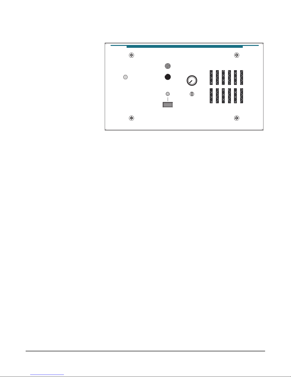
ro
Intercom Level
Answer Back
Talk
Program Level
Mic
Call Waiting
• The answer-back facility
offers several features
including an answer-back
button, a call-waiting
light, and the ability to
answ er subsequent calls
from unselected labels.
• The ICS-21/21DT
features intercom and
program-level controls.
Figure 1: Front Panel
Answer-Back Facility
The answer-back facility answers calls from stations or interfaces that the station
has not currently selected.
Call-Waiting Light
This dual-function light:
• is steadily lit when a call signal is received.
• flashes to indicate a call-waiting signal, which has priority over a call signal.
Answer-Back Button
This three-function button:
• sends a call signal to programmed label when the call-waiting light is off.
• The internal microphone
provides hassle-free use.
1-2
• directs audio to the longest-waiting call in the call-waiting stack when the
call-waiting light is flas hing.
• ends the current conversation from the call-waiting stack when the
call-waiting light is steadily on.
Answer-Back Stack
The answer-back stack tracks incoming calls from any label that is not assigned
to the station. These calls are availa ble in the order they were received. The
length of time the calls are available before they are automatically removed is set
in the configuration program.
The label assigned to the station will never appear in the answer-back stack
Note:
and duplicate labels are never added.
ICS-21/21DT SPEAKER STATION
Page 7

Answering a Call from the Answer-Back Stack
To answer a call from the answer-back stack:
1. Press and release the answer-back button to select the longest-waiting call.
2. Press the answer-back button while responding. The call-waiting light will be
on steadily.
• The call-waiting light does
not light when a call is
rece ived from a
programmed label.
• Note: The configuration
program can be set to
also send an audible
signal through the
speaker, whic h can only
be heard if the intercom
level is turned up.
Terminating Calls Answered with the Answer-Back Button
To terminate the call answered with the answer-back button, turn off th e
call-waiting light, and recover the previous call:
• The receiving station can terminate the call by pressing and releasing the
answer-back button.
• The calling station can terminate the call.
Answering Another Call from the Answer-Back Stack
To answer another call from the answer-back stack:
• If the calling station disconnected the call, the call-waiting light will flash.
• If the receiving station disconnected th e call, a call from an other unselected
label will be activated when the answer-back button is released.
Sending a Call Signal
The answer-back button can send call signals to a station or interface currently
on the selected talk/listen path when the call-waiting light is not on. Th e light
will turn on when the button is pressed and turn off when it is released.
Receiving a Call Signal
The call-waiting light turns on when another station sends a call signal and
remains on during the call.
• Note: Forcing the
trimpots past their stop
points will damage them.
ICS-21/21DT SPEAKER STATION
Intercom-Level Control
This control sets the speaker’s required listen level, but does not affect the
program-input level.
Program-Level Control
This control sets the program input’s audio level in the panel speaker.
Integral Microphone
This microphone is built into the front panel.
1-3
Page 8

Tone Alerts
Tone alerts are set through the configuration program. The station has the
following three tones:
TONE MEANING
• You can remotely control
the ICS-21 speaker
station.
• Remotely controlled
operation must be set up
both in the ICS-21 and in
the Matrix System.
Four rapid beeps Call signal
Two beeps Label change
Single beep Monitoring
Table 1: Tone Alerts
REMOTELY CONTROLLED OPERATION
The ICS-21 can be progr ammed to be r emotely contr olled. Th is featur e can be a
benefit when the ICS-21 is used in a location where it is not possible for the
person speaking on it to control it. This feature can also be used to remotely
monitor locations.
Remotely controlled operation must be enab led both in the ICS-21 and in the
Matrix System. To set remotely controlled operation in the ICS-21, use the
following steps:
1. Remove power from the ICS-21.
2. Remove or partially remove the ICS-21 from its outlet box or enclosure.
1-4
3. Set Option Switches S1-2 and S1-3 to the ON position, towards the front
panel. Refer to Figure 2.
4. Fasten the ICS-21 into its box or enclosure and reconnect power.
To set remotely controlled operation fo r the ICS-21 in the Matrix System, use
the following steps in PGM-WIN progr a m:
1. From the FILE menu, select ON-LINE TO MATRIX.
2. From the SETUP menu, select HARDWARE and LABELS. Assign labels to
the stations by clicking on the TALK LABEL for the port the station is
connected to and typing in the label you want the station to have. For this
example, the ICS-21 station will be named ICS21 and the master station will be
named 2003.
3. Select the ATTACHMENTS tab.
4. Click on the ROUTES button.
ICS-21/21DT SPEAKER STATION
Page 9

5. Click on EDIT SOURCE-DESTINATION.
6. Highlight the ICS21 label. Click on route SOURCE.
7. Highlight the 2003 label. Click on route DESTINATION.
8. Click on END EDITS.
9. Select the ACTIVATE WITH LISTEN check box and the AVAILABLE
check box.
10. From the CONFIGURE menu, select ATTACHMENTS.
• Control the ICS-21
speaker station remotely
when the operator needs
to be hands-free.
11. Click the STATION button and double-click ICS21.
12. Click on ROUTE 1. This will move the route from the left window to the
right.
13. Click the KEY ASSIGNMENTS tab.
14. Double-click the 2003 label and click on the desired Talk key. This will
place the ICS21 label on that key's talk and listen.
15. Click SELECT NEW and double-click ICS21. Select 2003 by highlighting
it and then click on the white box below TALK near the graphic of the station.
(LISTEN will automatically track.)
16. Select the LOCAL PEREFENCES tab.
17. Disable CAL L SIGN AL T O NES fo r ICS-21 label. (This is optional. It will
prevent the four call-signal beeps from sounding each time you set a talk to the
ICS-21 station.)
18. Select the GLOBAL ADVANCED tab.
19. Select the AUTO-SIGNAL check box for the ICS21 label.
20. Click APPLY.
ICS-21/21DT SPEAKER STATION
1-5
Page 10
• The station’s internal
controls provide the
ability to customize the
ICS-21/21DT to
numerous applications.
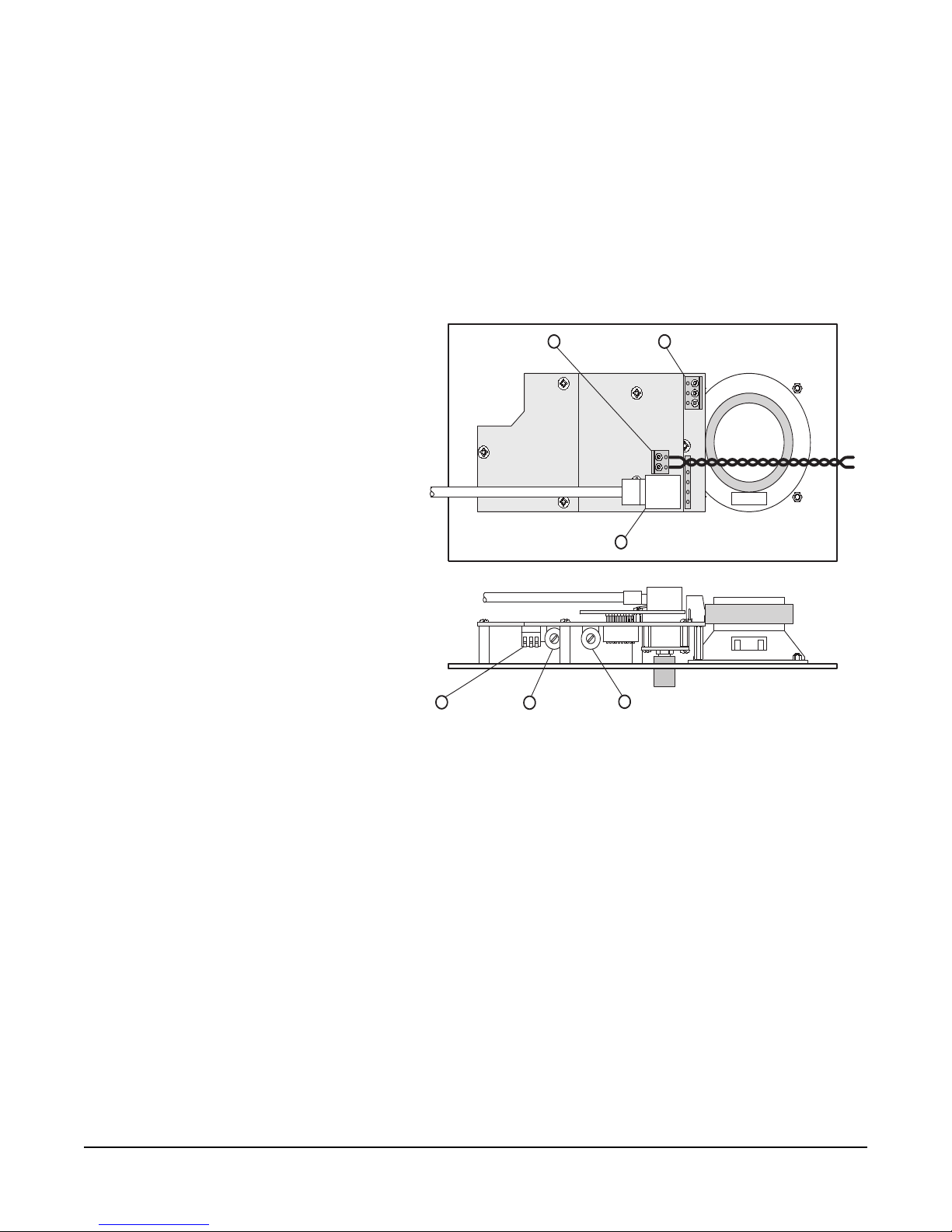
INTERNAL ADJUSTMENTS AND CONNECTIONS
The controls and connectors inside the ICS-21/21DT are shown in Figure 2 on
page 1-6. They can be adjusted without completely removing the panel from its
wall box or D T-Box e n c l os ure by re moving the t op t w o screws and l oo se n ing the
bottom two screws a few turns. The panel can then be tilted out from the wall to
make the controls accessible as shown in the lower view of Figure 2 on page 1-6.
VIEW FROM TOP OF
ICS-21
3
OPTION SWITCHES
POWER CONNECTION
6
321
1
CALL ALERT TONE LEVEL CONTROL
4
2
MINIMUM VOLUME CONTROL
PROGRAM INPUT
5
MATRIX CONNECTOR
FRONT PANEL
• An RJ-45 provides audio
and data communications
to the Matrix frame.
1-6
Figure 2: Internal Controls
Call-Alert Tone-Level Control (1)
This control must be disabled by turning the control fully counterclockwise.
Minimum-Volume Control (2)
This control adjusts the minimum setting of the intercom-level control on the
front panel. This is normally adjusted when the system is set up and shouldn’t
need to be adjusted during normal operation. This feature can be disabled by
turning the control fully counterclockwise.
Option Switches (3)
Of the three option switches, only S1-1 should be configured when the system is
set up, and should not be changed in normal operation. The other two switches
(S1-2 and S1-3) should remain in the off position. The ON position of each
switch is toward the circuit board and the OFF position is toward the front
panel.
ICS-21/21DT SPEAKER STATION
Page 11

• The minimum-volume
control assures that the
volume cannot be
completely turned off.
Internal Microphone Gain (S1-1)
This switch determines the microphone’s sensitivity. When the switch is in the
ON position (default), talking should be done within 2 ft. of the front panel. If it
is necessary to talk from a greater distance, the switch should be turned OFF.
Remotely Controlled Operation (S1-2 and S1-3)
These switches set either normal or remotely controlled operation. When they
are in the OFF position, operation is normal and the talk/listen function is
controlled by the Talk button. When they are in the ON pos ition, the talk/
listen function is remotely controlled by another Matrix station. Both switches
must be in either the ON or OFF position. The ICS-21 will not function if S1-2
and S1-3 are in different positions.
Matrix Connector (4)
This eight-wire modular jack (RJ-45) provides an audio and data
communications link to the Matrix system.
Program-Input Connector(5)
A three-terminal, plug-on connector provides the program input to the station.
Program is fed to the speaker. This level is controlled by t he program-leve l
control. The program-input connector accepts a balanced or unbalanced
line-level audio signal from -20 dBv to +10 dBv. If this input is connected to the
stage announce (SA) output of a main station, it can be used as a paging input.
Because the level of this input is independently adjustable from the intercom
audio volume, it can be used to override the intercom audio in all modes except
remote listen-page. The program input is also independent of the mode setting.
The pinout of the program-input connector is as follows.
• The program-input
connector provides
program input to the
station.
ICS-21/21DT SPEAKER STATION
PIN NUMBER FUNCTION
1 Ground (shield)
2 Positive signal
3 Negative signal
Table 2: Pinout Information
PIN 1
ICS-21/21DT PROGRAM
INPUT CONNECTOR
2
3
1
XLR CONNECTOR
1-7
Page 12

• The station can obtain
power from three
sources.
• Note: Both 10-VA C and
16-VAC doo rbell
transformers are
commonly available at
hardwar e stor es, but only
the 16-VAC transformers
are suitable in this case.
Figure 3: Program Input Connector Wiring
Power Connection (6)
The station requi re s local power, which can come from vario us sources,
including:
16-VAC Doorbell Transformer
A doorbell transformer can be attached to a separate box containing the
power-line connection and the low-voltage, 16-VA C can be routed to the
connector on the EB-4W circuit board. This connection is especially useful if the
headset or speaker station is installed in a wall.
14-VAC Wall-Mounted Power Supply
A Clear-Com wall-mounted po wer supply (part number 400008) can be used for
powering the station from 120 VAC. (Use part number 400011 for 220 VAC
power.) This connection is a better choi ce if the headse t or speake r is mounted in
a desktop box, such as a Clear-Com DT-Box, which is not located on a wall.
24- to 28-VDC Source
The headset or speaker station can be powered from a DC source, such as
batteries.
To connect the selected power supply:
1. Connect the two w ires from the power so urce to the two-position, plug-on
terminal strip.
2. Plug this connector onto the circuit board as shown in Figure 2 on page 1-4.
1-8
ICS-21/21DT SPEAKER STATION
Page 13

ICS-21/21DT SPEAKER STATION
1-9
Page 14

2
QUICK START
• Users can use the “Quick
Start” approach to get
their stations up and
running in minutes.
• Note: When the station
is initially powered, the
call-waiting lamp will
blink slowly indicating the
station is attempting to
communic a te w ith the
Matrix frame. Once
communication is
established, the blinking
will stop.
1. Unpack the unit and insp e ct i t fo r any damage th at may h av e o ccu rred during
shipping.
2. Set the option switches to the default (toward the front panel) position.
3. Connect the RJ-45 connector to the Matrix frame.
4. Connect 14- to 18-VAC power to the two-terminal, plug-on connector.
5. Install the ICS-21/21DT into the four-gang outlet box or DT-Box.
6. Set listen levels (see “Intercom-Level Cont rol” on page 3).
7. The speaker station should now be operating properly.
8. Read the rest of this manual for further information.
ICS-21/21DT SPEAKER STATION
2-1
Page 15

•
ICS-21/21DT SPEAKER STATION
Page 16

ICS-21/21DT SPEAKER STATION
Page 17

3
INSTALLATION
• The ICS-21/21DT runs
on 14- to 18-VAC power.
• Note: If the station is to
be installed in a DT-Box,
the back cover of the DTBox must first be
removed. It is retained
with four screws. Feed the
power cable through one
slot and fasten it to the
strain relief as shown in
Figure 4 at right.
1. Connect the 14- to 18-VAC power to the two-position terminal strip. Plug the
terminal strip onto the P2 as show in Figure 2 on page 1-6.
2. Connect the eight-wire, modular RJ-45 conn ect or to J1 as shown in Figure 2
on page 1-6.
3. If the RJ-45 Matrix connector should need to be unplugged, use the following
procedure.
1. Remove power from the station.
2. If th e station is insta lled in a DT-Box, remove the front panel. It is
retained with four screws.
3. Using long-nosed pliers, grasp the top and bottom of the plug so that the
retaining clip will be depressed. Pull the plug out with the pliers.
• Removing the RJ-45
Matrix connector requires
three steps.
Figure 4: DT-Box Wiring
ICS-21/21DT SPEAKER STATION
3-1
Page 18

ICS-21/21DT SPEAKER STATION
Page 19

4
MAINTENANCE
TROUBLESHOOTING TIPS
Listed below are some of the more common problems the station may
experience, their possible causes, and suggested solutions.
SYMPTOM CAUSE SOLUTION
• Sometimes when the talk
light doesn’t work it’s
because the station isn’t
receiving power.
• When the system doesn’t
operate, make sure there
isn’t an incompatibility
problem.
System does not operate
and the talk light does
not turn on when talk
button is pressed.
System does not operate
and the talk light does
not turn on when talk
button is pressed.
System does not operate
and the call-waiting
light blin ks slowly.
System does not operate
and the call-waiting
light blinks quickly.
The station is not
receiving 14- to
16-VAC power.
The station has an has
an internal failure.
Communication with
the system is lost.
1. S1-2 and/or S1-3 are
not off.
2. An incompatibility
problem with the
Matrix system.
Check the circuit
powering the station
and make sure all plug
connections are secure.
The station requires
servicing.
Make sure each
eight-wire, modular
connector is securely
plugged in, check th e
wiring, and ensure that
the Matrix system is
turned on.
1. Turn S1-2 and/or S1
off, then remove and
restore power to the
station.
2. Contact the dealer or
Clear-Com’s technical
service.
ICS-21/21DT SPEAKER STATION
System operates
incorrectly. The talk
light does not come on
when talk button is
pressed or stays on until
talk button is pressed.
The speaker is off when
it should be on.
Operating mod e
switches are set
incorrectly.
Refer to the section of
this manual on option
switches (page 1-5).
4-1
Page 20

SYMPTOM CAUSE SOLUTION
• System feedback can
have three different
causes.
Speaker does not
operate, but the talk
light comes on when
1.The intercom-level
knob is turned all the
way down.
talk button is pressed.
2.The speaker plug or
wiring has come loose.
Hum or buzz in system. Inductive pickup caused
by close proximity of
this speaker station or
connected stations to
power lines or
transformers.
System feedback
(acoustical).
The intercom-level
control at this station or
another station is set t oo
high.
System feedback
Channel unterminated. Set the main station or
(acoustical).
1. Adjust control
appropriately.
2. Make sure speaker is
connected internally.
Relocate the offending
unit or wiring.
Adjust.
power supply
termination switch for
the appropriate channel
to the ON position.
• When the program signal
is distorted, ch eck
whether the progra m
input is getting too much
signal.
System feedback
(acoustical).
The station’s
microphone is too close
to an open speaker on
another station.
Program signal sounds
distorted.
Program signal sounds
distorted.
The program-le vel
control is set too h igh.
The program input
circuit is overloaded.
Rapid clicking noise. 1. Defective wiring or
connectors.
2. Defective IC1 on
710533 assembly.
Turn down the speaker
or change the u nit’s
location.
Turn the
program-level control
counterclockwise.
Reduce the gain of the
program signal at the
source, such as an audio
mixer.
1. Repair/replace wiri ng
or connectors.
2. Replace IC1.
4-2
ICS-21/21DT SPEAKER STATION
Page 21

TECHNICAL REFERENCE
Speaker
Volume
Intercom
Speaker
Mute
Min
Input
Program
Balanced
Mute
Program
Call
Level
Vol
Program
Back
Answer
Light
Waiting
Receive
Call Send &
Matrix
Connector
Mic Gain
LIM
EQ/
Mic Mute
Panel Mic
ICS-21/21DT SPEAKER STATION
Talk
Power
Mode
Options
Operating
Microprocessor
Microprocessor
Talk
Rectifier
16 V AC
Matrix
Interface
Figure 5: ICS-21/21DT Block Diagram
4-3
Page 22

Figure 6: Main PCB Component Layout
4-4
ICS-21/21DT SPEAKER STATION
Page 23

BILL OF MATERIALS
ICS-21/21DT Main PCB
CAPACITORS
Value Type Volts To l. Part # Designator
220 uF Aluminum 35V 150021 C5 C18
22 uF Tantalum 16V 150032 C21 C24
4.7 uF Aluminum NP 50V 150087 C13
100 uF Aluminum 35V 150136 C25 C45
22 pF Ceramic Disc 50V 5% 151116 C14
47 pF Ceramic Disc 50V 5% 151120 C7 C19 C30
C36
220 pF Ceramic Disc 50V 5% 151128 C26
390 pF Ceramic Disc 50V 5% 151131 C10
470 pF Ceramic Disc 50V 5% 151132 C17
.0015uF Ceramic Disc 50V 5% 151138 C11
.0047uF Ceramic Disc 50V 10% 151156 C27
.01 uF Ceramic Disc 50V 10% 151160 C32 C33 C35
C38 C44
.047 uF Ceramic Disc 50V 10% 151168 C23 C37
.1 uF Ceramic Disc 50V 10% 151172 C3 C4 C12
C15 C29 C39
C40 C41 C46
C47
.22 uF Ceramic Disc 50V 10% 151176 C16 C22 C28
.47 uF Tantalum 35V 10% 151184 C31 C34
1 uF Tantalum 16V 10% 151185 C6 C20 C43
4.7 uF Tantalum 16V 10% 151189 C8
10 uF Tantalum 25V 10% 151192 C42
ICS-21/21DT SPEAKER STATION
RESISTORS
Value Power Type Tol. Part # Designator
10 OHM 1/4 Carbon Film 5% 410002 R19 R45
390 OHM 1/4 Carbon Film 5% 410005 R39
1.3K OHM 1/2 Carbon Film 5% 410075 R28
2.2 OHM 1/10 SMD 5% 411181 R27
100 OHM 1/10 SMD 1% 411293 R40
301 OHM 1/10 SMD 1% 411339 R41
432 OHM 1/10 SMD 1% 411354 R15
475 OHM 1/10 SMD 1% 411358 R10
1.00K OHM 1/10 SMD 1% 411389 R29
1.21K OHM 1/10 SMD 1% 411397 R17
1.50K OHM 1/10 SMD 1% 411406 R31
2.00K OHM 1/10 SMD 1% 411418 R14 R38
3.24K OHM 1/10 SMD 1% 411438 R26
4.75K OHM 1/10 SMD 1% 411454 R20
5.62K OHM 1/1O SMD 1% 411461 R18
6.19K OHM 1/10 SMD 1% 411465 R23
8.25K OHM 1/10 SMD 1% 411477 R42
4-5
Page 24

10.0K OHM 1/10 SMD 1% 411485 R8 R44
12.1K OHM 1/10 SMD 1% 411502 R13 R33
20.0K OHM 1/10 SMD 1% 411514 R12 R24 R32
33.2K OHM 1/10 SMD 1% 411535 R43
47.5K OHM 1/10 SMD 1% 411550 R2 R4
68.1K OHM 1/10 SMD 1% 411565 R35 R36
100K OHM 1/10 SMD 1% 411581 R5 R21
121K OHM 1/10 SMD 1% 411589 R22
221K OHM 1/10 SMD 1% 411614 R48
475K OHM 1/10 SMD 1% 411646 R46 R47
1.0M OHM 1/10 SMD 5% 411677 R49
10K O HM X4 SMD DIP Isolated 1% 416016 R1 R7 R9
47K OHM X4 SMD DIP Isolated 1% 416018 R3
100K OHM X4 SMD DIP Isolated 1% 416019 R6
Po t 10K TRIMPOT 470058 R34 R30
Po t 5K TRIMPOT 470063 R37
Po t 5K POT 470081 R25
DIODES AND TRANSISTORS
Device Description Part # Designator
LED LOW CURRENT GREEN LED 390021 D8
LED LED, YLW ULTRA BRGHT 390057 D3
IC LM384 POWER 4W AMP 480012 IC5
IC 7805L POS 5V REG 480088 IC10
Diode BAV70 DUAL DIODE 481019 D1 D7
IC LM833 DUAL OP AMP 481023 IC1 IC2 IC8
Transistor 2907A PNP 60V 600MA 481027 Q2
Diode BAV99 DUAL DIODE 481033 D2 D5 D6
Transistor MPSA14 DNPN 30V 300MA 481038 Q4
IC DG444 QUAD CMOS ANALOG SW 481050 IC4
Transistor J175 P-CHANNEL JFET 481056 Q1
Diode 5.1V 5% ZENER 1/4W 481061 D4
Transistor MPSA64 DPNP 30V 500MA 481075 Q3
IC MICROPROCESSOR, KB/MR SERIES 710508 IC9
4-6
MISCELLANEOUS
Device Description Part # Designator
Connector 3 POS, SCREW TERM. PLUG-IN 210370 P2
Pot SHAFT PIHER POT GRY 240043 R30 R34
Pot PIHER TRIMPOT SHAFT, GREY 240057 R37
Po t KN OB GREY INSERT 240077 R25
Button ROUND MINIATURE BTN, BK 240081 S2
Button RECT. MINIATURE BTN, BK 240082 S3
Lens LENS, YELLOW, ROUND 240099 D3
Speaker 2 1/2 IN. SPKR 16 OHM 3.5W 500103
Panel M ic ELE CTRE T MIC ELEME NT W/PI NS 500132
Switch DPDT P.B. 510107 S2 S3
Switch DIP SWITCH PIANO 3 POS 510114 S1
RUBBER MIC MOUNT 640027
ICS-21/21DT SPEAKER STATION
Page 25

123
P2
BALANCED
PROGRAM
123
P5
C46
.1uF
C20
+
+
R43
33.2K*
C47
.1uF
36
PREAMP
3
D2
BAV99
R20
AMPLIFIER
1445
1
1uF
C18
220uF
R21
100K*
-
6
R23
R22
120K*
R2
R1A
10K*
R1B
10K*
4.7K*
C25
100uF
IC5
LM384
-
6
VOLUME
3 1
7
IC2B
+
5
6.2K*
47K*
12
+V1
27 1 8
SPEAKER OUTPUT
+
C29
R27
2.2
.1uF
8
13
45
12
11
10
R7D
10K*
3
7
C30
47pF
+
2
C28
.22uF
C27
.0047uF
R26
3.24K*
2
13
4
+V3
12
R29
1K*
C4
.1uF
VDD
3 1
Bias
2
R25
5K POT
2
CW
R30
10K POT
CW
LM833
R24
C26
C23
.047uF
C22
.22uF
Bias
7
-
6
14
15
R1C
+
C21
MIN.
4-WIRE
OPTION
(1)
1234567
8
P3
1234567
8
J3
20K*
Bias
220pF
R28
1.3K 1/2W
+V2
IC1B
LM833
+
5
R4
47K*
C24
22uF
+
16
+V2
IC4D
DG444
R31
1.5K*
C31
+
D4
5.1V
4 5
+V2 +V2 +V2
R6D
100K*
10K*
36
22uF
R32
5
D3
.47uF
20K*
VOLUME
(INTERNAL)
CALL
R6C
1
C36
47pF
7
IC8B
LM833
R35
+
5
6
Bias
R7C
10K*
R7B
10K*
3 6
2 7
IC4A
DG444
3
2
1
R34
10K POT
ALERT
TONE
3 1
C32
.01uF
CW
C35
.01uF
Bias
R33
15K*
R49
1MR5
CALL
LIGHT
Q4
MMBTA14
100K
C34
.47uF +
SIGNAL
R48
220K
C33
.01uF
+V2
3
D5
BAV99
3
1 2
12
D6
BAV99
Q3
MMBTA64
13
VDD
100K*
2
R1D
3 6
354
6
CALL
S2
VDD
C3
.1uF
C43
E
+V1
+V3
10
10
9
9
8
8
4-WIRE
OPTION (2)
7
7
6
6
5
5
4
4
3
3
2
2
1
D
C
B
A
1
TW POWER
OPTION
P1
J1
5
4
3
2
1
INTERCOM
CHANNEL
P4
27
47pF
INTERCOM
LINE
DRIVER
R42
8.2K*
Q2
MMBT2907A
+V1
213
+V1
IC4C
DG444
10
R47
470K* C7
9
11
R46
3
Q1
MMBFJ175
21
R10
475*
1uF
+
1
VOut
GND
VIn
IC10
7805L
3
C45
100uF
+
+
R39
390
R40
100*
R19
3
1 2
R15
430*C13
4.7uF
C12
1
.1uF
R3B
47K*
IC2A
8 4
+
-
+V1
3
2
R3A
47K*
1 8
C15
R16
12.1K*
.1uF
+
C6
1uF
R13
15K*
C11
.0015uF
C10
390pF
R12
20K*
R14
2K*
470K*
+
S1A
C8
4.7uF
POWER
2
+V2
C42
10uF
10
R45
10
+
C5
220uF
D7
BAV70
C19
47pF
INTERCOM
LINE
RECEIVER
Bias
Bias
LM833
45
R3D
47K*
R3C
47K*
C14
22pF
1
+V1
IC1A
LM833
8 4
+
3
2
+V1
R17
1.2K*
510114
1 6
MIC SENS
R18
5.6K
C17
470pF
C16
.22uF
123
4
J2
PANEL
MIC
INPUT
C40
.1uF
C39
.1uF
18
27
R6A
100K*
R6B
100K*
Bias
R36
68.1K*
3
2
8 4
+
-
+V1
IC8A
LM833
1
68.1K*
18
R7A
10K*
7
IC4B
DG444
6
VOLUME
Bias
C37
.047uF
R8
10K*
R44
10K*
1 2
VDD
12345
P6
PROGRAMMING / TEST INTERFACE
1 - Gnd / Gnd
2 - Data / Strobe
3 - n/a / Data Out
R37
5K POT
CW
3 1
2
8
D1
BAV70
3
C41
.1uF
6
VDD
4 - Clock / Clock
5 - MCLR (not) / Data In
6 - +5V / n/a
PROGRAM
VOLUME
R38
2K*
R9B
10K*
RC010RC19RC28RC37RC46RC5
VDD1VSS
RB013RB112RB211RB34RB43RB5
R9A
10K*
Bias
D8
27
5
2
18
1
354
2
Green
R41
300*
IC9
PIC16C505
14
R9D
10K*
45
36
VDD
R9C
10K*
S1B
510114
S1C
510114
2 5
3 4
C44
.01uF
6
TALK
S3
OPERATING MODE S1B S1C
Normal OFF OFF
Remote Page OFF ON
Remote Listen ON OFF
Remote Listen-Page ON ON
1. ALL RESISTORS ARE 1/10W 5% LISTED IN OHMS
2. ALL CAPACITORS ARE LISTED IN MICROFARADS
NOTES: (UNLESS OTHERWISE SPECIFIED)
E
D
C
B
45
10K*
C38
.01uF
A
4 4
Figure 7: ICS-21/21DT Schematic (identical to Clear-Com’s KB-212 schematic)
ICS-21/21DT SPEAKER STATION
3 3
2 2
1 1
4-7
Page 26

T2
P3
R5
R2
C6
IC3
R7
Z3
R8
C5
T1
R3
D3
P1
CLEAR-COM
Matrix Option PCB
R6
C3
C2
R10
C4
R4
IC2
IC1
ASSY #710533
COPYRIGHT (C) 1999
R1
C1
P2
Q1
16-18
VAC
PWR
D1
P4
J1
R9
Figure 8: Matrix Option PCB Component Layout
4-8
CAPACITORS
Value Type Volts To l. Part # Designator
10 uF Aluminum 50V 150064 C6
.022 uF Monolithic 50V 10% 150082 C5
.1 uF Monolithic 100V 10% 150085 C4
.0022uF Monolithic 50V 10% 150108 C3
100 uF Aluminum 35V 150136 C2
2200 uF Aluminum 35V 20% 150163 C1
RESISTORS
Value Power Type Tol. Part # Designator
2K OHM 1/4 Carbon Film 5% 410014 R5
47K O HM 1/4 Carbon Film 5% 410021 R6
1.5K OHM 1/4 Carbon Film 5% 410055 R8
330 OHM 1/4 Carbon Film 5% 410061 R9
100 OHM 1/4 Carbon Film 5% 410071 R1 R7
2.2M OHM 1/4 Carbon Film 5% 410153 R10
10K OHM X5 SIP ISOLATED 415003 R2
ICS-21/21DT SPEAKER STATION
Page 27

4.7K OHM X 4 SIP ISOLATED 415008 R4
100K OHM X4 SIP ISOLATED 415014 R3
DIODES AND TRANSISTORS
Device Description Part # Designator
Diode 1N4148 SIGNAL 10MA 75PIV 480000 D3
Transistor TIP41 NPN 40V 6A TO-220 POWER 480099 Q1
Diode 1.5A 200V BRIDGE 480158 D1
INTEGRATED CIRCUITS
Device Description Part # Designator
IC LM833N 480175 IC3
IC MAX488E 480231 IC1
MISCELLANEOUS
Device Description Part # Designator
Transformer600CT/600CT 560018 T2
Transformer10K:10K 560034 T1
IC MICRO, KB/MR MATRIX OPTION 710532 IC2
Connector 2 POS HSING, SCRW TRM. 210369 P2
ICS-21/21DT SPEAKER STATION
4-9
Page 28

E
VDD
VDD
D
VDD
C
P4
Programming / Test / Vdd /
Interrogation Connection
B
R4B
4.7K
34
C4
VDD
1
2
3
4
5
6
VDD
5
IC1
MAX488E
1
.1uF
D3
1N4148
1
R4D
78
R4A
R4C
4.7K
R9
330
6
8
-++
3
2
910
RC010RC19RC28RC37RC46RC5
VDD
RB013RB112RB211RB34RB43RB5
4.7K
1 2
4.7K
5 6
7
5
2
R10
-
2.2MR2E
VSS
4
10K
IC2
PIC16C505P
14
1234567
J1
1
T1
MET-09
C3
.0022uF
C5
R3D
VDD
MATRIX
.022uF
R5
2K
/Ch. A
100K
7 8
CONNECTOR
8
2
6
534
Sense Talk
Call Button
Latch Disable
R2C 10K
5 6
Q1
TIP41
6
3
2
R6
R2D
47K
10K
1
2
534
1234567
P3
123456789
P1
7 8
Call Light
IC3A
LM833
84
-
2
1
R1
100
T2
1
TTC108
R7
3
100
+
R2B
34
R2A
+
10K R8 1.5K
10K
R3C
100K
5 6
SPARES:
C6
10uF
+
7
IC3B
LM833
+
5
6
8
4-WIRE
OPTION
10
VDD
1 2
CONNECTORS
E
D
C
B
R3A
100K
12
VDD
R3B
100K
A
PROGRAMMING / TEST / INTERROGATION
1 - Gnd /Gnd /Gnd
2 - Data/Strobe Out /Strobe In
3 - n/a/Data Out /Data In
4 - Clock/Clock Out/Clock In
VDD
5 - MCLR (not)/Data In/Data Out
6 - +5V / +5V/ +5V
4 4
4-10
/Ch. C
3 4
J2
P5-6
C2
+
/Ch. D
1
1
J3
P5-7
3 3
2
D1
1
C1
-+
4
P2
2200uF 35V
3
1
2
16-20
VAC
100uF
2 2
1. ALL RESISTORS ARE 1/4W 5% LISTED IN OHMS
2. ALL CAPACITORS ARE LISTED IN MICROFARADS
NOTES: (UNLESS OTHERWISE SPECIFIED)
A
1 1
Figure 9: Matrix Option Schematic
ICS-21/21DT SPEAKER STATION
Page 29

5
SPECIFICATIONS
Panel Microphone Pre-Amp
Input Type Electret
Pre-Amp Response Curve
Frequency Response 250 Hz to 12 kHz, contoured for intelligibility
Limiter Range 20 dB
Speaker Amplifier
Speaker Type 2.5 in. round, 16 ohm
Power Output 2 W into 16 ohms
Frequency Response 200 Hz to 15 kHz, ±3 dB
Signal-to-Noise 75 dB
Distortion < 0.5% THD at 1 kHz
Speaker Level 98 dB SPL at 3 ft.
Program Amplifier
(Transformer less, balanced
differential input)
Input Level -20 dBV
Input Impedance > 100k ohm
Frequency Response 150 Hz to 15 kHz, ± 3 dB
Power Requirements
Voltage 16 to 18 VAC
Current 100 mA average
Internal Connectors
Intercom eight-wire modular connector
Program three-position, plug-on screw terminals
AC Power two-position, plug-on screw term inal s
Internal Controls
(3) Option switches; (1) Minimum Volume Level control
Front Panel Controls & Indicators
(1) Program-level control; (1) Intercom-volume control; (1) T alk button; (1) Answer-back
button; (1) Talk light; (1) Call-waiting light
Environmental
32° to 122° F (0° to 50° C)
Dimensions
8.25 in. W x 4.5 in. H x 1.75 in. D (210 mm x 114 mm x 44 mm)
ICS-21/21DT SPEAKER STATION
5-1
Page 30

Weight
ICS-21 1.14 lb. (0.51 kg)
ICS-21DT 4.06 lb. (1.83 kg)
Notice About Specifications
While Clear-Com makes every attempt to maintain the accuracy of the inform at ion
contained in its product manuals, that information is subje c t to chang e wit hout noti ce.
Performance specifications included in this manual are design-center specifications and are
included for customer guidance and to facilitate system installation. Actual operating
performance may vary.
5-2
ICS-21/21DT SPEAKER STATION
Page 31

6
CLEAR-COM LIMITED WARRANTY
• Return Authorization
Numbers are required for
all returns.
• Warranty and non-
warranty repairs are
available. Contact the
factory.
The Clear-Com warranty does not cover any defect, malfunction, or failure
caused beyond the control of Clear-Com, including unreasonable or negligent
operation, abuse, accident, failure to follow instructions in the manual, defective
or improperly associated equipment, attempts at modification and repair not
authorized by Clear-Com, and shipping damage. Products with their serial
numbers removed or defaced are not covered by this warranty.
This warranty is the sole and exclusive express warranty given with respect to
Clear-Com products. It is the responsibility of the user to determine before
purchase that this product is suitable for the user's intended purpose.
Any and all implied warranties, including the implied warranty of
merchantability are limited to the duration of this express limite d warranty.
Neither Clear-Com nor the dealer who sells Clear-Com products is liable for
incidental or consequential damages of any kind.
For your own records fill in the information below:
Model No. Ser ial No.
Date Purchased
Purchased from (dealer)
Address
City State ZIP
FACTORY SERVICE
Do not return any equipment to the factory without firs t obtaining a Return
Authorization Number.
All equipment returned for repair must be accomp anied by documentation
stating the return address, telephone number, date of purchase, and a description
of the problem.
Send equipment to be repaired to:
Customer Service Department
Clear-Com Intercom Systems
4065 Hollis Street
Emeryville, CA 94608-3505
Telephone: (510) 496-6666
Fax: (510) 496-6610
Web site: www.clearcom.com
WARRA NTY REPA IR
If in warranty, no charge will be made for the repairs. Equipment being returned
for warranty repair must be sent prepaid and will be returned prepaid.
ICS-21/21DT SPEAKER STATION
6-1
Page 32

NON-WARRANTY REPAIR
Equipment that is not under warranty must be sent prepai d to Clear-Com. If
requested, an estimate of repair costs wi ll be issued prior to service. Once rep air is
approved and repair of equipment is completed, th e equipment will be shipped
freight collect from the factory.
6-2
ICS-21/21DT SPEAKER STATION
 Loading...